
Analysis of a Nature-Inspired Shape for a Vertical Axis Wind Turbine


 ,
, 
Abstract
:1. Introduction
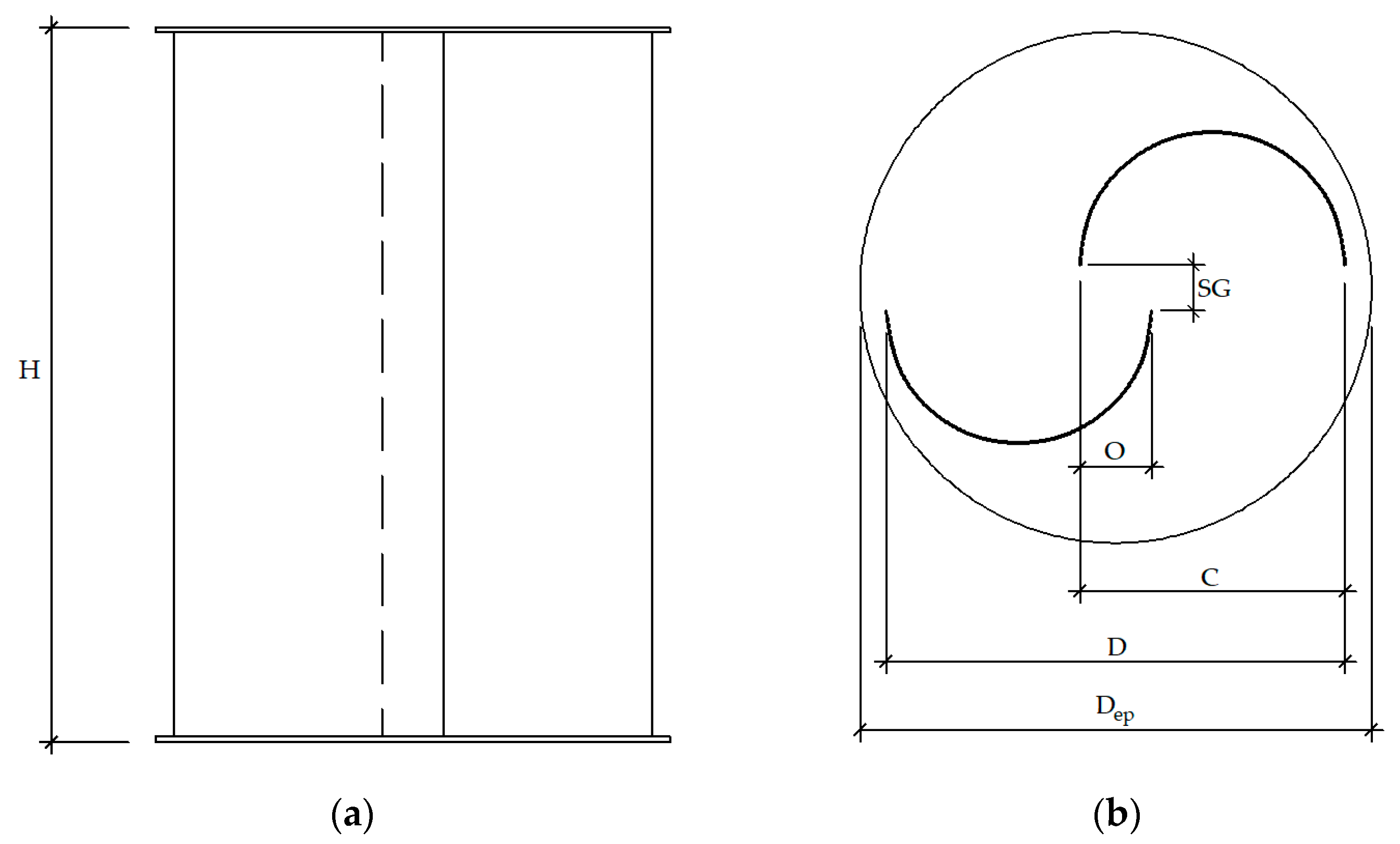
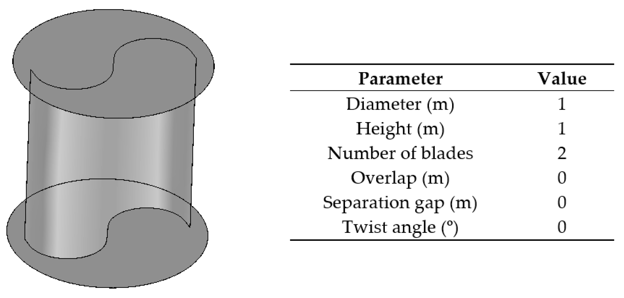
1.1. Aspect Ratio
1.2. Overlap
1.3. Separation Gap
1.4. Number of Blades
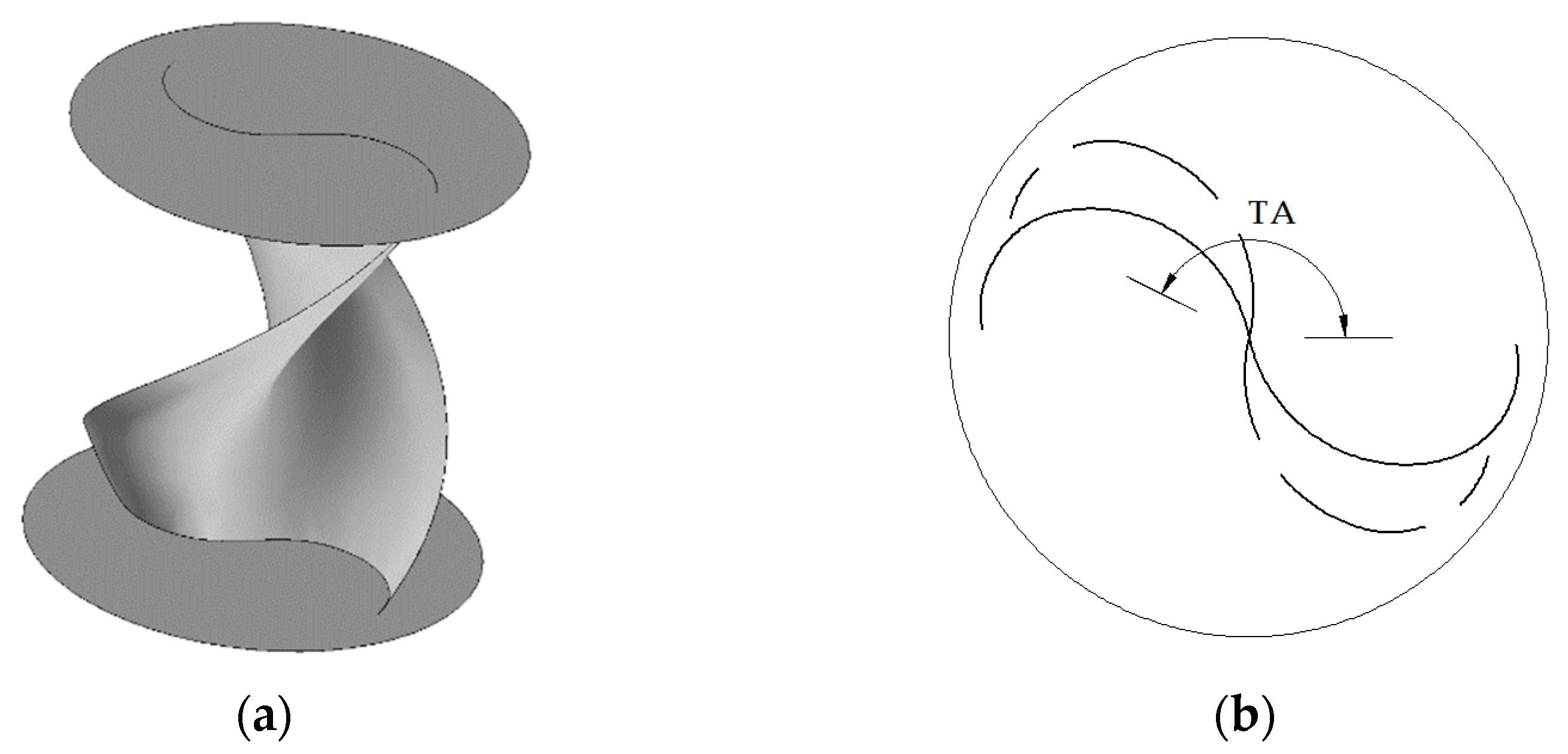
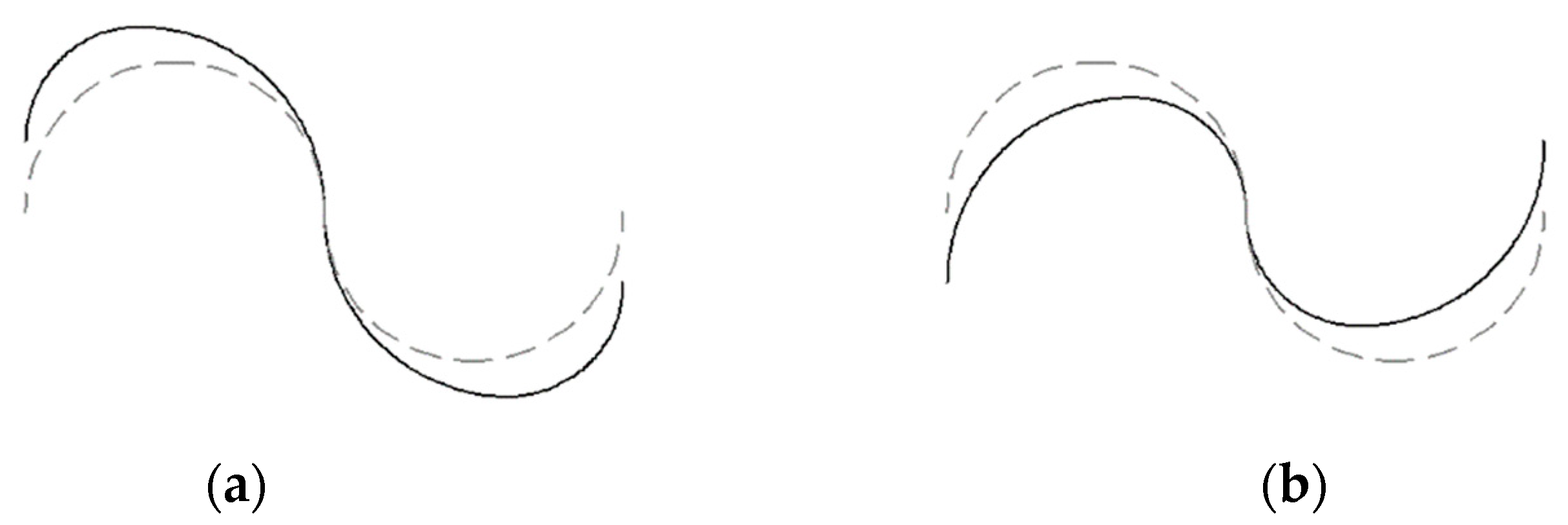
1.5. Twist Angle
1.6. Blade Profile
2. Materials and Methods
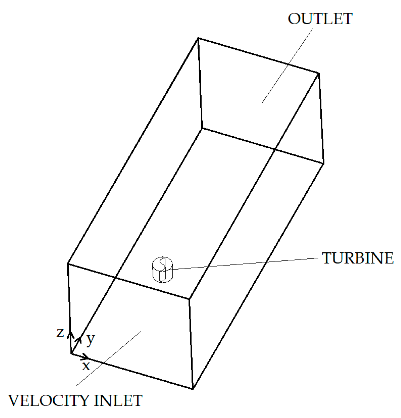
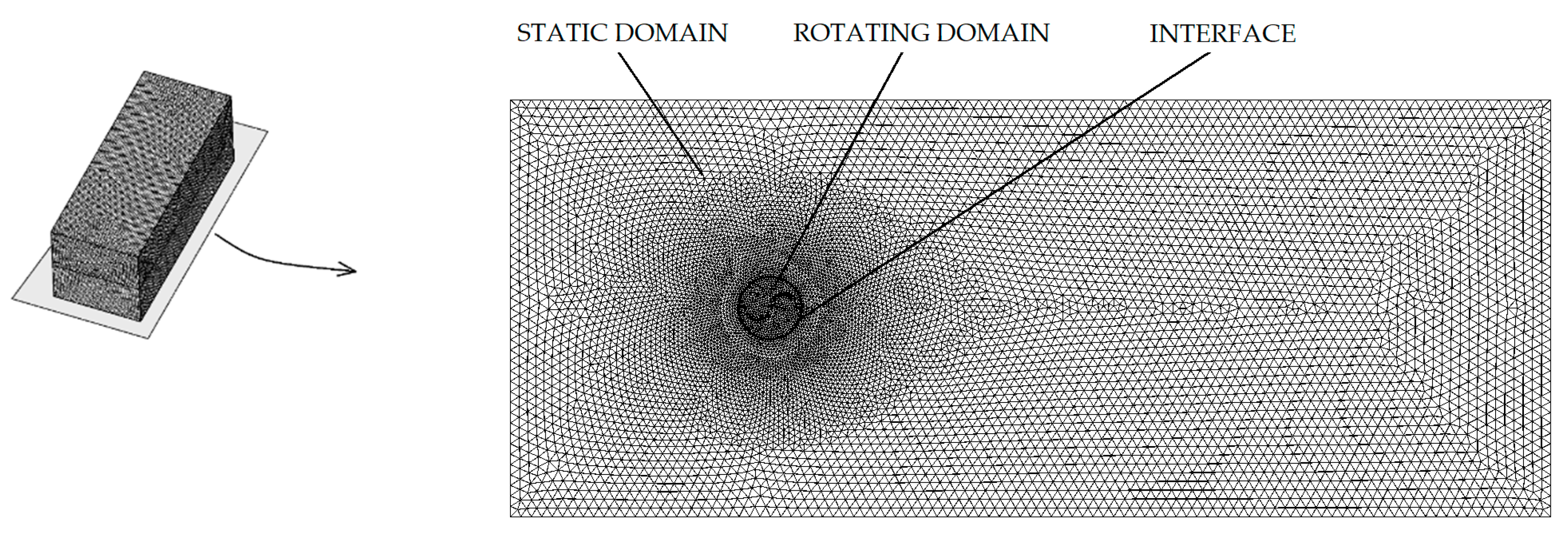
2.1. Numerical Model
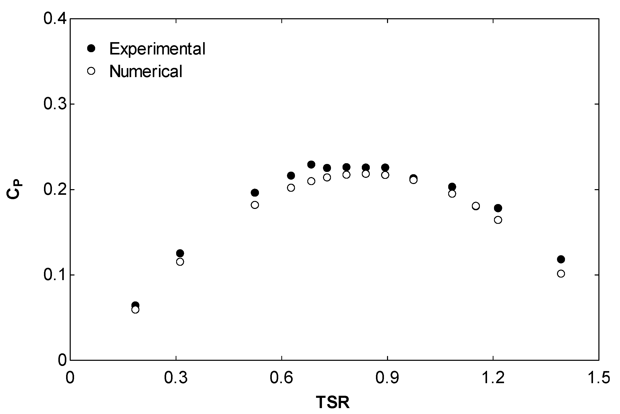
2.2. Validation of the Results
3. Results and Discussion
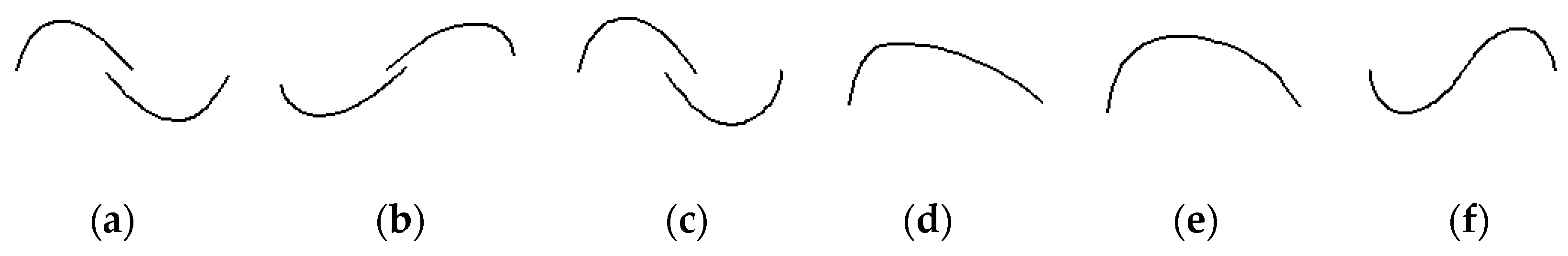
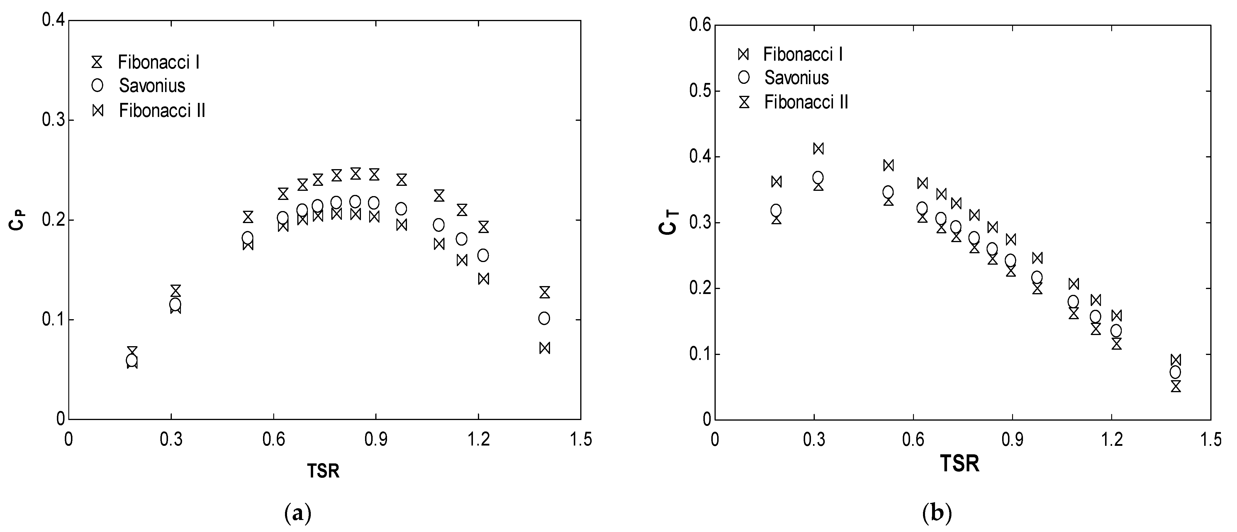
3.1. Fibonacci Sequence
3.2. Design Aspects in the Fibonacci Blade Profile
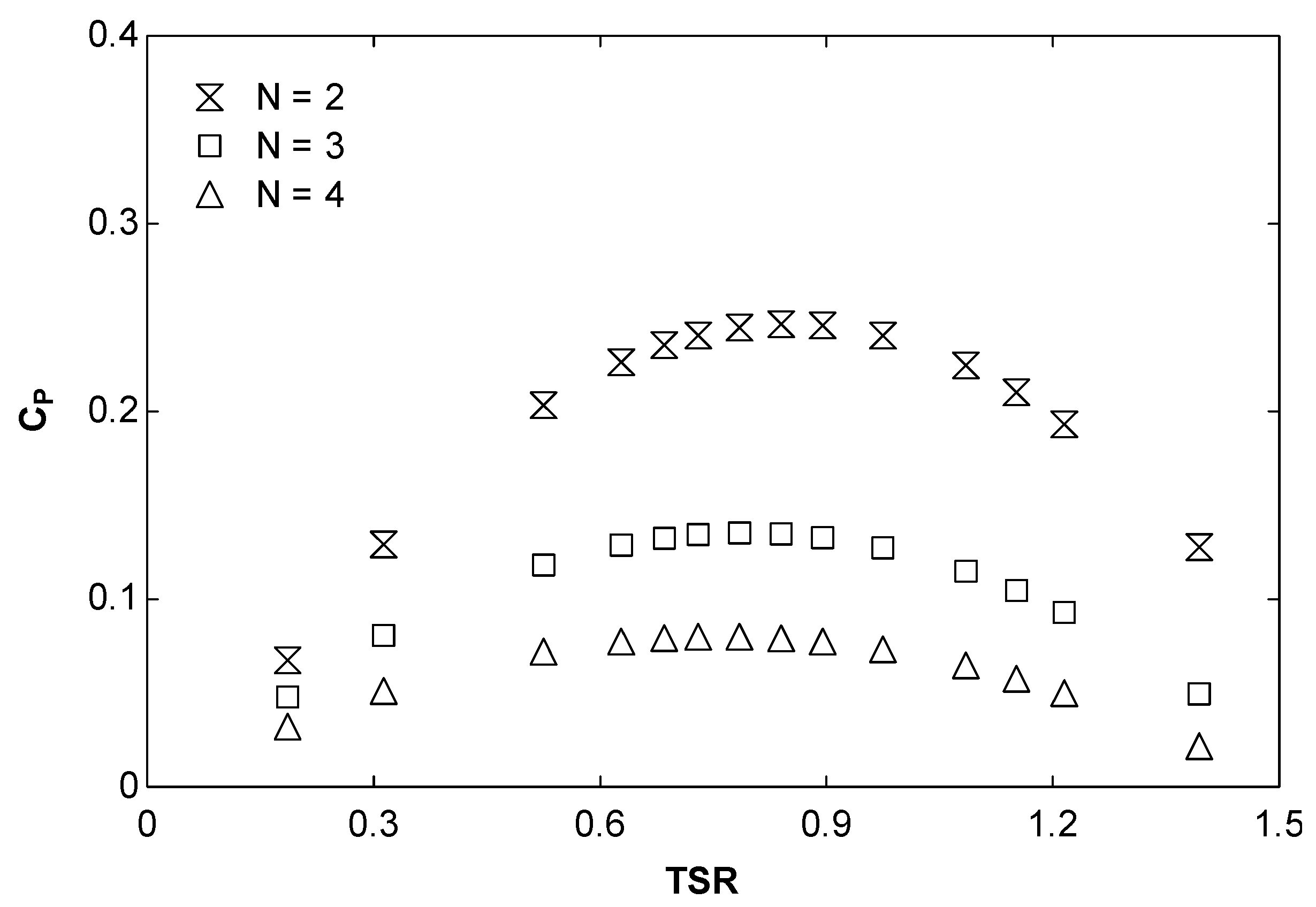
3.2.1. Effect of the Number of Blades
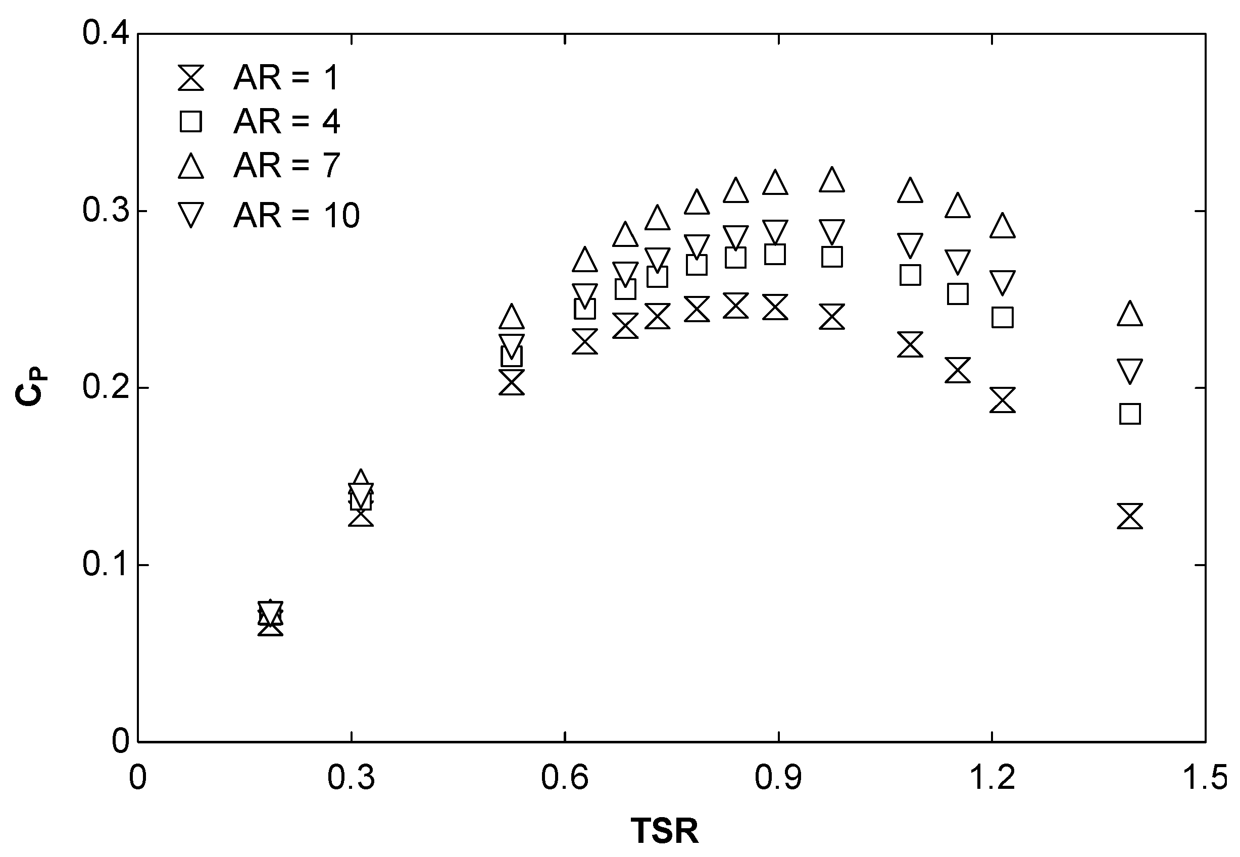
3.2.2. Effect of the Aspect Ratio
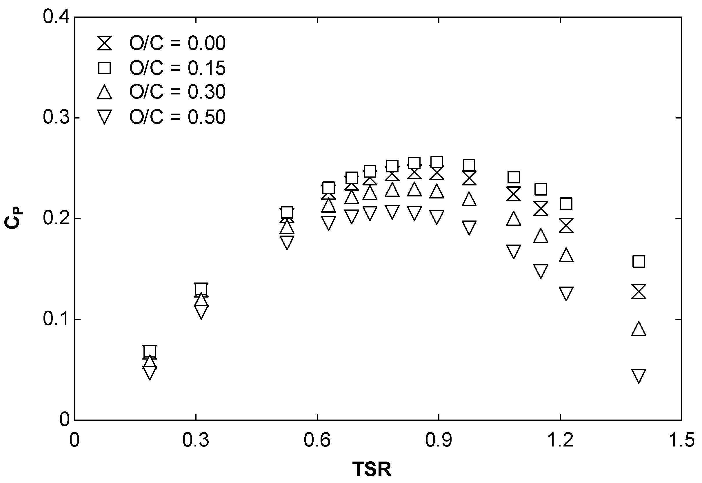
3.2.3. Effect of the Overlap
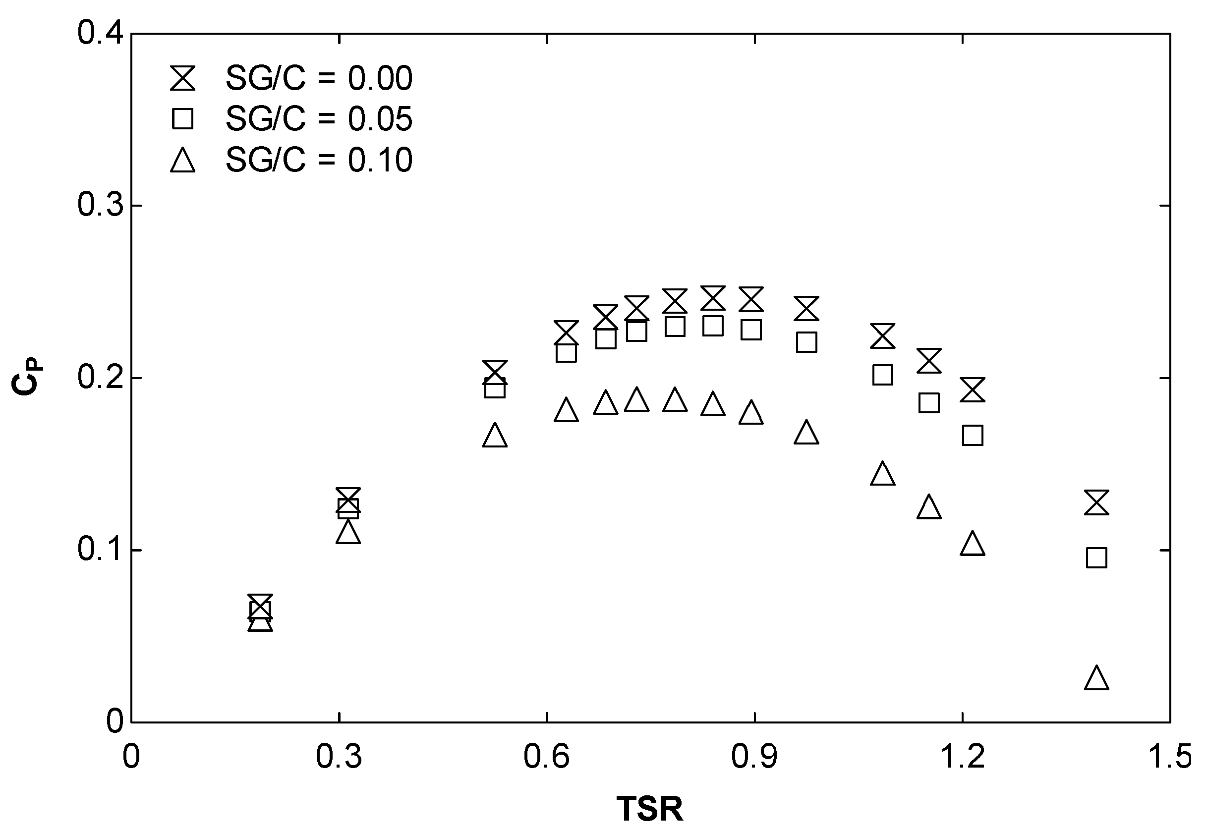
3.2.4. Effect of the Separation Gap
3.2.5. Effect of the Twist Angle
4. Conclusions
- -
- The optimum number of blades are two;
- -
- The optimum aspect ratio is seven.
- -
- The optimum overlap/chord length relation is 0.15.
- -
- The optimum separation gap is 0.
- -
- The optimum twist angle is 180°.
Author Contributions
Funding
Institutional Review Board Statement
Informed Consent Statement
Conflicts of Interest
References
- Liu, Y.; Xiao, Q.; Atilla, I.; Peyard, C.; Wan, D. Establishing a fully coupled CFD analysis tool for floating offshore wind turbines. Renew. Energy 2017, 112, 280–301. [Google Scholar] [CrossRef] [Green Version]
- Liu, Z.; Tu, Y.; Wang, W.; Qian, G. Numerical analysis of a catenary mooring system attached by clump masses for improving the wave-resistance ability of a spar buoy-type floating offshore wind turbine. Appl. Sci. 2019, 9, 1075. [Google Scholar] [CrossRef] [Green Version]
- Blanco, J.; Lamas, M.I.; Couce, A.; Rodriguez, J.D. Vertical Axis Wind Turbines: Current Technologies and Future Trends. In Proceedings of the International Conference on Renewable Energies and Power Quality, A Coruña, Spain, 25–27 March 2015. [Google Scholar]
- Pagnini, L.C.; Burlando, M.; Repetto, M.P. Experimental power curve of small-size wind turbines in turbulent urban environment. Appl. Energy 2015, 154, 112–121. [Google Scholar] [CrossRef]
- Vita, G.; Šarkić-Glumac, A.; Hemida, H.; Salvadori, S.; Baniotopoulos, C. On the wind energy resource above high-rise buildings. Energies 2020, 13, 3641. [Google Scholar] [CrossRef]
- Wijayanto, R.P.; Kono, T.; Kiwata, T. Performance characteristics of an orthopter-type vertical axis wind turbine in shear flows. Appl. Sci. 2020, 10, 1778. [Google Scholar] [CrossRef] [Green Version]
- Savonius, S.J. The S-rotor and its applications. Mech. Eng. 1931, 53, 333–338. [Google Scholar]
- Talukdar, P.K.; Sardar, A.; Kulkarni, V.; Saha, U.K. Parametric analysis of model Savonius hydrokinetic turbines through experimental and computational investigations. Energy Convers. Manag. 2018, 158, 36–49. [Google Scholar] [CrossRef]
- Zhang, Y.; Kang, C.; Zhao, H.; Teng, S. Effects of in-line configuration of drag-type hydrokinetic rotors on inter-rotor flow pattern and rotor performance. Energy Convers. Manag. 2019, 196, 44–55. [Google Scholar] [CrossRef]
- Alipour, R.; Alipour, R.; Koloor, S.S.R.; Petru, M.; Ghazanfari, S.A. On the Performance of Small-Scale Horizontal Axis Tidal Current Turbines. Part 1: One Single Turbine. Sustainability 2020, 12, 5985. [Google Scholar] [CrossRef]
- Alipour, R.; Alipour, R.; Fardian, F.; Koloor, S.S.R.; Petru, M. Performance improvement of a new proposed Savonius hydrokinetic turbine: A numerical investigation. Energy Rep. 2020, 6, 3051–3066. [Google Scholar] [CrossRef]
- Akwa, J.V.; Vielmo, H.A.; Petry, A.P. A review on the performance of Savonius wind turbines. Renew. Sustain. Energy Rev. 2012, 16, 3054–3064. [Google Scholar] [CrossRef]
- Tian, W.; Song, B.; VanZwieten, J.; Pyakurel, P. Computational fluid dynamics prediction of a modified Savonius wind turbine with novel blade shapes. Energies 2015, 8, 7915–7929. [Google Scholar] [CrossRef]
- Pujol, T.; Massaguer, A.; Massaguer, E.; Montoro, L.; Comamala, M. Net power coefficient of vertical and horizontal wind turbines with crossflow runners. Energies 2018, 11, 110. [Google Scholar] [CrossRef] [Green Version]
- Vance, W. Vertical Axis Wind Rotors—Status and potential. In Proceedings of the Conference on Wind Energy Conversion Systems, Washington, DC, USA, 11–13 June 1973; pp. 96–102. [Google Scholar]
- Saha, U.K.; Thotla, S.; Maity, D. Optimum design configuration of Savonius rotor through wind tunnel experiments. J. Wind Eng. Ind. Aerodyn. 2008, 96, 1359–1375. [Google Scholar] [CrossRef]
- Alexander, A.J.; Holownia, B.P. Wind tunnel tests on a savonius rotor. J. Wind Eng. Ind. Aerodyn. 1978, 3, 343–351. [Google Scholar] [CrossRef]
- Zhao, Z.; Zheng, Y.; Xu, X.; Liu, W.; Hu, G. Research on the Improvement of the Performance of Savonius Rotor Based on Numerical Study. In Proceedings of the 2009 International Conference on Sustainable Power Generation and Supply, Nanjing, China, 6–7 April 2009; pp. 1–6. [Google Scholar] [CrossRef]
- Sheldahl, R.E.; Blackwell, B.F.; Feltz, L.V. Wind tunnel performance data for two- and three-bucket Savonius rotors. J. Energy 1978, 2, 160–164. [Google Scholar] [CrossRef] [Green Version]
- Fujisawa, N. On the torque mechanism of Savonius rotors. J. Wind Eng. Ind. Aerodyn. 1992, 40, 277–292. [Google Scholar] [CrossRef]
- Mojola, O.O. On the aerodynamic design of the savonius windmill rotor. J. Wind Eng. Ind. Aerodyn. 1985, 21, 223–231. [Google Scholar] [CrossRef]
- Menet, J.L.; Bourabaa, N. Increase in the Savonius rotors efficiency via a parametric investigation. In Proceedings of the European Wind Energy Conference, London, UK, 22–25 November 2004. [Google Scholar]
- Lee, J.H.; Lee, Y.T.; Lim, H.C. Effect of twist angle on the performance of Savonius wind turbine. Renew. Energy 2016, 89, 231–244. [Google Scholar] [CrossRef]
- Damak, A.; Driss, Z.; Abid, M.S. Experimental investigation of helical Savonius rotor with a twist of 180°. Renew. Energy 2013, 52, 136–142. [Google Scholar] [CrossRef]
- Damak, A.; Driss, Z.; Abid, M.S. Optimization of the helical Savonius rotor through wind tunnel experiments. J. Wind Eng. Ind. Aerodyn. 2018, 174, 80–93. [Google Scholar] [CrossRef]
- Kumar, G.; Ram, V.R.; Kumar, N. Numerical analysis of different blade profile of wind turbine. Int. J. Appl. Eng. Res. 2018, 6, 375–385. [Google Scholar]
- Alom, N.; Saha, U.K. Influence of blade profiles on Savonius rotor performance: Numerical simulation and experimental validation. Energy Convers. Manag. 2019, 186, 267–277. [Google Scholar] [CrossRef]
- Kacprzak, K.; Liskiewicz, G.; Sobczak, K. Numerical investigation of conventional and modified Savonius wind turbines. Renew. Energy 2013, 60, 578–585. [Google Scholar] [CrossRef]
- Benesh, A.H. Wind Turbine System Using a Savonius-Type Rotor. U.S. Patent 5494407A, 27 February 1996. [Google Scholar]
- Mohamed, M.H.; Janiga, G.; Pap, E.; Thévenin, D. Optimal blade shape of a modified Savonius turbine using an obstacle shielding the returning blade. Energy Convers. Manag. 2011, 52, 236–242. [Google Scholar] [CrossRef]
- Chan, C.M.; Bai, H.L.; He, D.Q. Blade shape optimization of the Savonius wind turbine using a genetic algorithm. Appl. Energy 2018, 213, 148–157. [Google Scholar] [CrossRef]
- Lamas Galdo, M.I.; Rodriguez Vidal, C.G. Hydrodynamics of biomimetic marine propulsion and trends in computational simulations. J. Mar. Sci. Eng. 2020, 8, 479. [Google Scholar] [CrossRef]
- Lamas, M.I.; Rodríguez, C.G.; Rodríguez, J.D. Optimization of the efficiency of a biomimetic marine propulsor using CFD. Ing. E Investig. 2014, 34, 17–21. [Google Scholar]
- Lamas, M.I.; Rodríguez, J.D.; Rodríguez, C.G. CFD analysis of biologically-inspired marine Propulsors. Brodogradnja 2012, 63, 125–133. [Google Scholar]
- Lamas, M.I.; Rodríguez, J.D.; Rodríguez, C.G.; González, P.B. Three-dimensional CFD analysis to study the thrust and efficiency of a biologically-inspired marine propulsor. Pol. Marit. Res. 2011, 18, 10–16. [Google Scholar] [CrossRef] [Green Version]
- U.S. National Oceanic and Atmospheric Administration. Public Domain. Available online: https://commons.wikimedia.org/wiki/File:Fran10.jpg (accessed on 10 July 2022).
- NASA; ESA. The Hubble Heritage Team (STScI/AURA). In Public Domain. Available online: https://commons.wikimedia.org/wiki/File:The_Two-faced_Whirlpool_Galaxy.jpg (accessed on 10 July 2022).
- Blanco, J.; Rodriguez, J.D.; Couce, A.; Lamas, M.I. Proposal of a nature-inspired shape for a vertical axis wind turbine and comparison of its performance with a semicircular blade profile. Appl. Sci. 2021, 11, 6198. [Google Scholar] [CrossRef]
- Altan, B.D.; Atılgan, M. An experimental and numerical study on the improvement of the performance of Savonius wind rotor. Energy Convers. Manag. 2008, 49, 3425–3432. [Google Scholar] [CrossRef]
- Plourde, B.D.; Abraham, J.P.; Mowry, G.S.; Minkowycz, W.J. Simulations of three-dimensional vertical-axis turbines for communications applications. Wind Eng. 2012, 36, 443–453. [Google Scholar] [CrossRef]
- Gallo, L.A.; Chica, E.L.; Flórez, E.G.; Obando, F.A. Numerical and experimental study of the blade profile of a Savonius type rotor implementing a multi-blade geometry. Appl. Sci. 2021, 11, 10580. [Google Scholar] [CrossRef]
- Zhang, H.; Li, Z.; Xin, D.; Zhan, J. Improvement of aerodynamic performance of Savonius wind rotor using straight-arc curtain. Appl. Sci. 2020, 10, 7216. [Google Scholar] [CrossRef]
- Akwa, J.V.; Alves da Silva Júnior, G.; Petry, A.P. Discussion on the verification of the overlap ratio influence on performance coefficients of a Savonius wind rotor using computational fluid dynamics. Renew. Energy 2012, 38, 141–149. [Google Scholar] [CrossRef]
- Blanco Damota, J. Perfil de Pala de Turbina Eólica de Eje Vertical de Diseño Bioinspirado: Estudio Comparativo y Optimización Mediante Modelo CFD Parametrizado. Ph.D. Thesis, Unviersidade da Coruña, A Coruña, Spain, 2022. [Google Scholar]
- Ross, I.; Altman, A. Wind tunnel blockage corrections: Review and application to Savonius vertical-axis wind turbines. J. Wind Eng. Ind. Aerodyn. 2011, 99, 523–538. [Google Scholar] [CrossRef]
- Parmanand, S. The So-called Fibonacci numbers in ancient and medieval India. Hist. Math. 1985, 12, 229–244. [Google Scholar] [CrossRef] [Green Version]
- Huntley, H.E. The Divine Proportion; Dover Publications Inc.: New York, NY, USA, 1970. [Google Scholar]
- Kamoji, M.A.; Kedare, S.B.; Prabhu, S.V. Experimental investigations on single stage modified Savonius rotor. Appl. Energy 2009, 86, 1064–1073. [Google Scholar] [CrossRef]
- Tartuferi, M.; D’Alessandro, V.; Montelpare, S.; Ricci, R. Enhancement of Savonius wind rotor aerodynamic performance: A computational study of new blade shapes and curtain systems. Energy 2015, 79, 371–384. [Google Scholar] [CrossRef]
- Ostos, I.; Ruiz, I.; Gajic, M.; Gómez, W.; Bonilla, A.; Collazos, C. A modified novel blade configuration proposal for a more efficient VAWT using CFD tools. Energy Conv. Manag. 2019, 180, 733–746. [Google Scholar] [CrossRef]
- Sharma, S.; Sharma, R.K. Performance improvement of Savonius rotor using multiple quarter blades—A CFD investigation. Energy Convers. Manag. 2016, 127, 43–54. [Google Scholar] [CrossRef]
- Chehouri, A.; Younes, R.; Ilinca, A.; Perron, J. Review of performance optimization techniques applied to wind turbines. Appl. Energy 2015, 142, 361–388. [Google Scholar] [CrossRef]
- Alipour, R.; Alipour, R.; Fardian, F.; Tahan, M.H. Optimum performance of a horizontal axis tidal current turbine: A numerical parametric study and experimental validation. Energy Conv. Manag. 2022, 258, 115533. [Google Scholar] [CrossRef]


| Mesh | Number of Elements | CP at TSR = 1 |
|---|---|---|
| Mesh 1 | 1.5 × 10⁶ | 0.226 |
| Mesh 2 | 2.9 × 10⁶ | 0.212 |
| Mesh 3 | 3.8 × 10⁶ | 0.207 |
| Mesh 4 | 4.5 × 10⁶ | 0.207 |
| Blade Profile | CP Improvement (%) | Reference |
|---|---|---|
| Batch | 10.5 | [48] |
| Elliptical | 10.3 | [28] |
| Airfoil | 10 | [49] |
| Elliptical | 17.81 | [50] |
| Elliptical | 8.89 | [51] |
| Elliptical | 11.34 | [52] |
| Blade Profile | CPmax | CF at P Max | SCPmax |
|---|---|---|---|
| Savonius | 0.217 | 0.2614 | 0.415 |
| Fibonacci I | 0.243 | 0.2886 | 0.421 |
| Fibonacci II | 0.205 | 0.2494 | 0.411 |
Publisher’s Note: MDPI stays neutral with regard to jurisdictional claims in published maps and institutional affiliations. |
© 2022 by the authors. Licensee MDPI, Basel, Switzerland. This article is an open access article distributed under the terms and conditions of the Creative Commons Attribution (CC BY) license (https://creativecommons.org/licenses/by/4.0/).
Share and Cite
Damota, J.B.; García, J.d.D.R.; Casanova, A.C.; Miranda, J.T.; Caccia, C.G.; Galdo, M.I.L. Analysis of a Nature-Inspired Shape for a Vertical Axis Wind Turbine. Appl. Sci. 2022, 12, 7018. https://doi.org/10.3390/app12147018
Damota JB, García JdDR, Casanova AC, Miranda JT, Caccia CG, Galdo MIL. Analysis of a Nature-Inspired Shape for a Vertical Axis Wind Turbine. Applied Sciences. 2022; 12(14):7018. https://doi.org/10.3390/app12147018
Chicago/Turabian StyleDamota, Javier Blanco, Juan de Dios Rodríguez García, Antonio Couce Casanova, Javier Telmo Miranda, Claudio Giovanni Caccia, and María Isabel Lamas Galdo. 2022. "Analysis of a Nature-Inspired Shape for a Vertical Axis Wind Turbine" Applied Sciences 12, no. 14: 7018. https://doi.org/10.3390/app12147018
APA StyleDamota, J. B., García, J. d. D. R., Casanova, A. C., Miranda, J. T., Caccia, C. G., & Galdo, M. I. L. (2022). Analysis of a Nature-Inspired Shape for a Vertical Axis Wind Turbine. Applied Sciences, 12(14), 7018. https://doi.org/10.3390/app12147018