Article

Microstructure and Mechanical Properties of (Ti, Nb)C Ceramic-Reinforced 316L Stainless Steel Coating by Laser Cladding

Mechanical and Power Engineering, Zhengzhou University, Zhengzhou 450001, China
*
Author to whom correspondence should be addressed.
Appl. Sci. 2022, 12(13), 6684; https://doi.org/10.3390/app12136684
Submission received: 4 June 2022 / Revised: 21 June 2022 / Accepted: 25 June 2022 / Published: 1 July 2022
(This article belongs to the Section Additive Manufacturing Technologies)

Abstract

:
The poor wear resistance of 316L stainless steel restricts further practical application. In this study, to improve its microhardness and wear resistance, the TiC and NbC ceramic particles were introduced to 316L powder fabricate (Ti, Nb)C ceramics-reinforced composite coatings by laser cladding. The effects of ceramics addition on the phase composition, microstructure, microhardness, and wear properties of the composite coating were investigated with an X-ray diffractometer, optical microscopy, scanning electron microscopy, a Vickers hardness tester, and a multi-functional surface performance tester. Results indicate that the TiC and NbC ceramic particles were distributed at the grain boundaries, effectively inhibiting the grain growth and refining the microstructure. The addition of ceramic particles could have decreased the temperature gradient and promoted the transformation from columnar crystals to equiaxed crystals. In addition, the microhardness was improved due to fine grain strengthening and solid solution strengthening. The friction coefficient and cross-sectional area of the composite coating were 0.381 and 8164.732 μm2, which was 0.846 and 0.603 times that of the 316L coating, respectively. Moreover, severe adhesive wear and plastic deformation was transformed into slight adhesive wear and abrasive wear due to the addition of TiC and NbC particles. This study provides new approaches to improving the wear resistance of 316L stainless steel and broadens its application.

1. Introduction

The 316L stainless steel provides excellent corrosion resistance and good toughness, and has been extensively applied in the marine, medical, machinery, oil and gas pipeline industries, and other fields [1,2,3]. However, as austenitic stainless steel, the low hardness and poor wear resistance of 316L stainless steel limit its wider application [4,5,6,7]. Surface strengthening techniques such as carburizing, nitriding, local heat treatment, and shot peening have been employed in practical applications to improve the surface properties of 316L steel [8,9]. Zhou et al. [10] investigated the effect of shot peening intensity on the surface integrity and fatigue life of 316L stainless steel. The microhardness was increased from 316 HV to 435 HV. The fatigue life was significantly improved. Peng et al. [11] adopted cryogenic gas carburizing technology to improve the hardness of 316L steel. The thickness of the carburizing layer was about 30 μm, and the fatigue life was increased by about 28%. Liu et al. [12] adopted different nitriding pressure, nitriding distance, and pressure to strengthen the surface of 316L stainless steel. The thickness of the nitriding layer can be adapted from 7 μm to 16 μm. However, the surface of parts peened by shot peening, carburizing, and nitriding techniques is generally restricted by the limited improved wear resistance and poor bond strength to the substrate.
In recent years, with the boom in laser additive manufacturing (AM) technology, laser cladding has become a leading technology because it can be employed to improve the hardness, wear resistance, and corrosion resistance of metal parts [13,14,15]. Compared with the traditional surface strengthening technology, the coating fabricated by laser cladding has the advantages of a low dilution rate, good metallurgical bond performance, and controllable microstructure and mechanical properties [16,17]. As a kind of composite material, metal-matrix composites provide both the wear resistance of ceramics and the toughness of matrix. It has attracted the attention of many academics and research teams. Zhao et al. [18] fabricated WC-reinforced 316L alloy composites with different volume fractions by using laser AM. Results showed that the microhardness of the composites was increased by 92%. However, the addition of WC also increased the crack sensitivity and porosity of the composites. Bandar et al. [19] explored the effects of different laser energy densities on the microstructure and mechanical properties of nano-TiC/316L composites by combining simulation and an experiment. The appropriate laser energy density can refine the microstructure and reduce the wear rate of the composites. Fei et al. [20] prepared an NbC-reinforced composite coating on the surface of a 316L stainless steel cardiovascular support, and test results showed that the hardness, elastic modulus, and wear resistance of the composite coating were superior to those of 316L stainless steel. Therefore, the fabrication of particles-reinforced composites by laser cladding is an effective way to improve the hardness and wear resistance of 316L stainless alloy. Reviewing the above literature, the addition of single ceramic particles often leads to agglomeration of ceramic particles, which is detrimental to improving the uniformity of the mechanical properties of the coating. Research [14,21] also indicates that TiC and NbC ceramics with high hardness, wear resistance, and thermal stability, can be considered as ideal candidates to strengthen the mechanical properties of 316L alloy. In addition, because TiC and NbC have similar lattice structures, Ti and Nb atoms in the lattice structure can be exchanged to form multi-carbide ceramics during the solidification process [16,22]. Therefore, the floating up phenomenon of low-density TiC can be suppressed effectively, leading to more uniform microhardness and mechanical properties.
In this study, the TiC and NbC ceramic particles of 10 wt% were added to 316L powder to prepare the composite powder, and then laser cladding technology was employed to fabricate the (Ti, Nb)C reinforced 316L composite coating on 45 steel. Furthermore, the effect of ceramics addition on the phase composition, microstructure, microhardness, and wear properties of the composite coating were obtained and analyzed in detail. It is expected that the results of this study can expand the practical application of 316L stainless steel.

2. Experimental Section

2.1. Materials

The deposition material is the 316L stainless steel spherical powder with the diameter range from 50 to 160 μm. Because of the wide applicability of 45 steel in many fields and good bonding performance with the Fe-based powder, the experiment was conducted on a 45 steel substrate with 100 × 100 × 10 μm3. The chemical composition of 45 steel and 316L stainless steel powder is listed in Table 1. The pureness of NbC and TiC ceramic particles is 99.99%, and their sizes are 1–4 μm and 6–10 μm, respectively. The experiment preparation process is shown in Figure 1. The addition of high-volume fractions of ceramics would result in poor fluidity of the powder and also increases crack sensitivity [14]. Conversely, the improvement in the wear resistance of the coating would be limited. Therefore, the 10 wt% TiC and 10 wt% NbC ceramic particles were first weighed and mixed with the 316L stainless steel powder. Then, planetary ball mills were employed to achieve the homogenization of composite powders with a mixing time of 60 min, where the mass ratio of alumina ball and powder was 2:1. Finally, the separated composite powder and 316LSS powder were dried for three hours. Before the experiment, the surface of the 45 steel was ground with 600 mesh SiC sandpaper to remove the dirt.

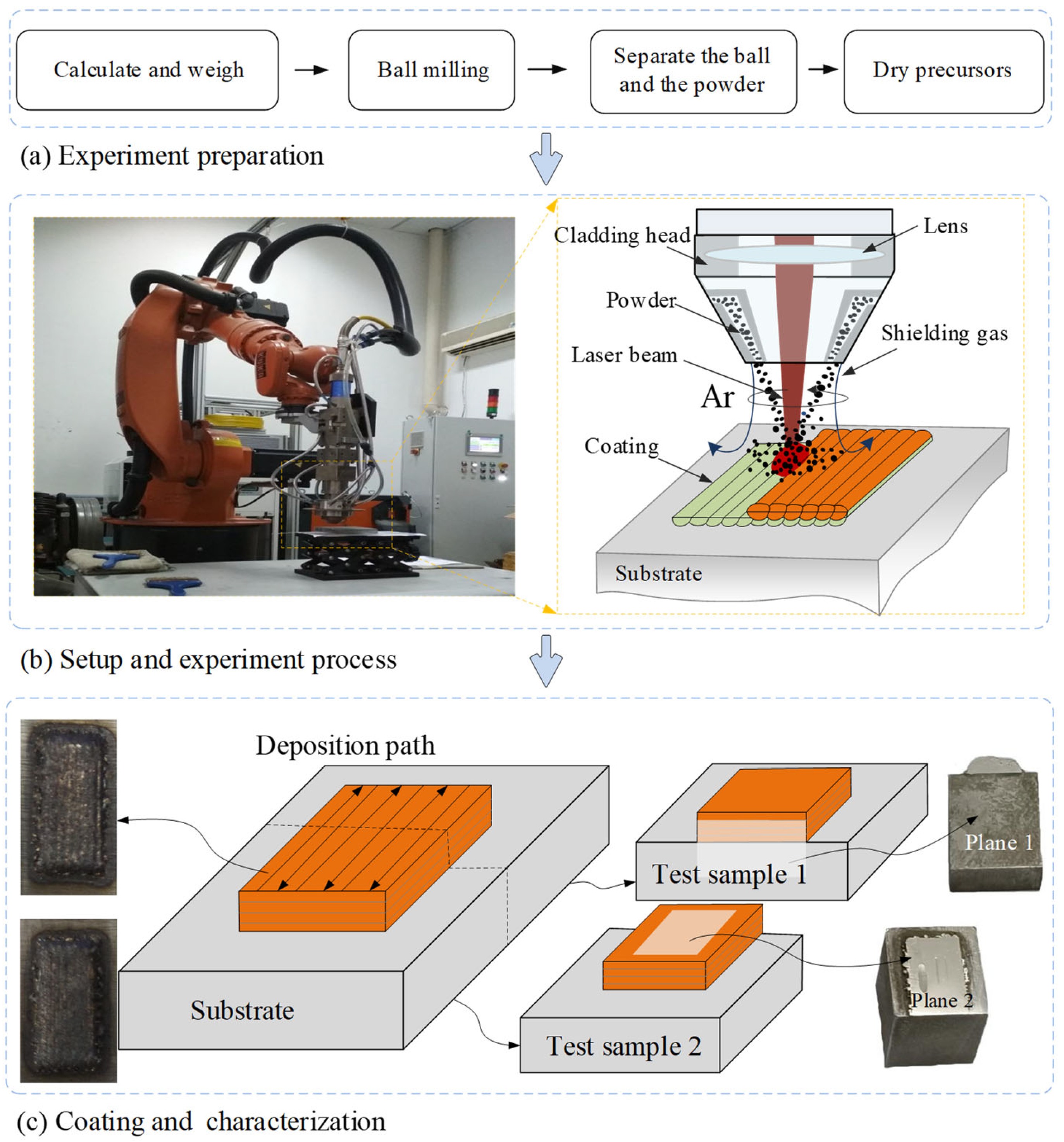
2.2. Setup and Process Parameters

The setup in the experiment is shown in Figure 1b, which is composed of an RC-52 cladding head, an RC-PGF-1 powder feeder, an IPG500 laser generator, a Kuka KR-16 robot, and an electric control cabinet. The experimental program was programmed, tested, and post-processed by an offline programming software (Robot-Art, Beijing, China). The program is imported into the controller to control the scanning path, scanning speed, and laser emission. The fabrication process of the coatings is shown in Figure 1. Four layers of coatings were prepared using a bow scan strategy, which contributes to the decrease in heat accumulation [23]. The optimal process parameters for four-layer coating by laser cladding are listed in Table 2. The shielding gas and the powder feeding gas are argon with a purity of 99.99%, and their flow rates are 15 L/min and 8L/min, respectively. The appearance of the 316L coating and composite coating fabricated in this study are also shown in Figure 1c.

2.3. Performance Measurement

The fabrication process of test samples is shown in Figure 1c. Each coating was cut into samples 1 and 2, perpendicular to the scanning direction by using a wire cutting machine tool (AQ400Ls, Sodick, Yokohama, Japan). The microstructure observation and hardness measurement were conducted on Sample 1. The phase identification and wear tests were conducted on Sample 2. Pane 1 and 2 are polished with 240#–2000# SiC sandpaper, then polished with a polishing paste of 2.5 μm, and cleaned with ultrasonic in ethanol for two minutes. Plane 1 was eroded in aqua regia for 10 to 20 s for the microstructure observation and the microstructure distribution at the indentation edge. An X-ray diffractometer (XRD) and scanning electron microscopy (SEM) equipped with energy dispersive analysis (EDS) were adopted for the composition and morphology of phases. A three-dimensional (3D) laser microscopy (OLS4100, Olympus, Kokyo, Japan) was used to obtain the optical microstructure. The microhardness of the coatings along the building direction was measured with a Vickers hardness tester (HV-1000, Shanghai, China), where a loading force and time were 300gf and 10 s, respectively. Since the thickness of the 316L and composite coatings approached 1.0 mm, the microhardness was measured at 10 evenly spaced points from the bottom to the top of the coating. A multi-functional surface performance tester (MFT-4000, Lanzhou, China) was used to obtain the friction and wear properties on plane 2. The parameters for the wear test were as follows: a GCr15 ball with a diameter of 5 mm, a load of 15 N, a reciprocating speed of 200 mm/min, the test time of 60 min, and the movement distance of 3 mm. In addition, the coefficient of friction (COF) was recorded automatically during the test process. The two-dimensional (2D) and 3D morphologies of the worn tracks and GCr15 ball were obtained with an OLS4100 to reveal the wear mechanism of coatings.

3. Results and Discussion

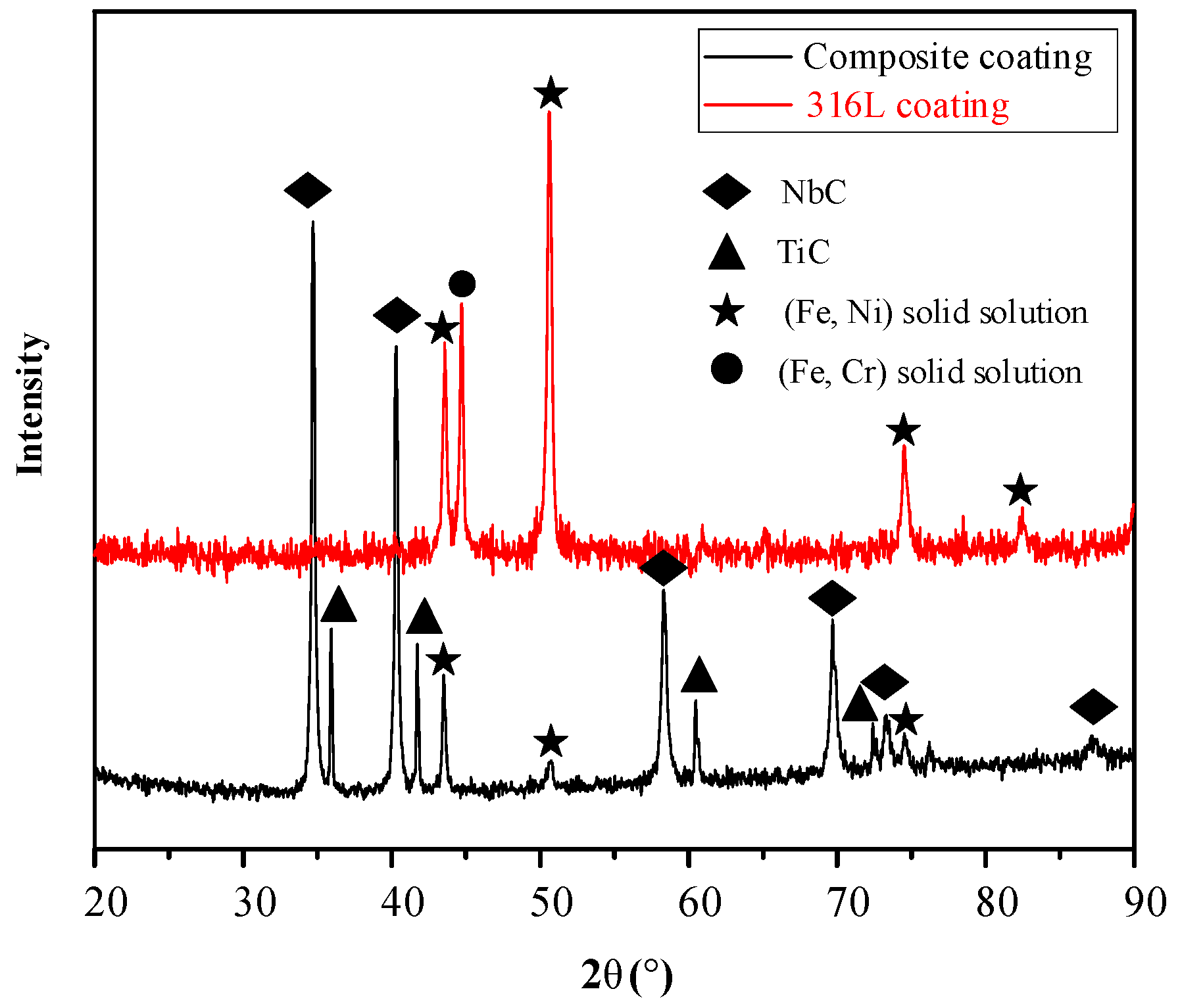
3.1. Phasecomposition

XRD test results for laser cladding the 316L coating and the composite coating are shown in Figure 2. The 316L coating is mainly composed of (Fe, Ni) solid solution and (Fe, Cr) solid solution, which is similar to the finding of previous research [7,24]. Compared with the 316L coating, some new peaks were detected according to the XRD curve of the composite coating. Diffraction peaks corresponding to TiC were detected at 35.89, 41.70, 60.48, and 73.34° (JCPDS card: 01-073-0472). Diffraction peaks of NbC were also detected at the corresponding positions (34.70°, 40.25°, 58.26°, 69.65°, and JCPDS card: 01-089-3690). XRD results show that new TiC and NbC ceramic phases were generated in the composite coating.

3.2. Microstructure of Coatings

Figure 3 shows the optical microstructures of the bottom, middle, and top regions of the 316L coating and the composite coating. It can be seen from Figure 3a that the 316L coating is mainly composed of coarse columnar crystals, cellular crystals, and fine equiaxed crystals in the different regions. At the bottom of the 316L coating, the grow direction of coarse columnar crystals is perpendicular to the interface between the 316L coating and the substrate. Previous studies [25,26] have found that the heat transfer direction of the molten pool is always along the direction of the maximum temperature gradient (G), which is perpendicular to the isotherm of the molten pool. In addition, during the solidification process, the temperature gradient at the bottom of the molten pool is the largest due to the good heat dissipation of the substrate. Moreover, the solidification rate (R) can be obtained according to Equation (1).
R = V s cos θ
where, Vs is scanning speed, and θ is the angle between the solidification front and the scanning direction. Therefore, the solidification rate of the single track decreases from the bottom to the top of the molten pool. The grain characteristics of the solidified coating are governed by a combination of G and R [27]. The large temperature gradient reduces the subcooling at the solidification front. The nucleation rate was effectively increased. However, the small solidification rate provides sufficient time for grain growth. As a result, coarse columnar crystals are formed at the bottom of the 316L coating, as shown in Figure 3. A visible remelting zone can be found in Figure 3. The grain morphology at the bottom of the single track is similar to that at the bottom of the coating, while the fine equiaxed crystals are concentrated at the top of the single track. As the liquid metal at the top of the melt pool is in contact with the cold shielding gas and air, the heat dissipation is mainly transferred to the air by convection and radiation. Therefore, the temperature gradient would be decreased. In addition, the increase in the solidification rate at the solidification front results in a decrease in G/R. This behavior promotes the generation of fine equiaxed crystals.
When 10 wt% NbC and 10 wt% TiC particles are added to the 316L powder, the microstructure of the composite coating fabricated by laser cladding is shown in Figure 3b1–b3). The microstructure of the composite coating has evolved significantly compared to the 316L coating. Some gray spherical particles are evenly distributed at the grain boundaries at the bottom, middle, and top of the composite coating. As shown in Figure 4, the SEM image indicates that the composite coating is mainly composed of the matrix phase (P1), the strip precipitate phase (P2 and 3), and gray spherical particles (P4 and 5). To identify the composition of these particles, energy spectral analysis (EDS) tests were performed, and the results are listed in Table 3. The region P1 mainly contains Fe, Cr, and Ni elements, which can be identified as austenite according to the XRD results. As shown in Figure 4, regions P2 and P3 are rich in Nb elements, indicating that Nb is the main component. EDS results show that the atomic ratio of Nb and C in the P2 and P3 regions was close to 1:1. Combined with the XRD results of composite coating, these could be confirmed as NbC ceramic particles. Similarly, gray spherical particles (P4 and 5) at the grain boundary can be regarded as TiC particles. Due to the low thermal conductivity of ceramic particles, the heat conduction in the molten pool along the temperature gradient is inhibited by the uniform distribution of TiC and NbC ceramic particles during the solidification process. Therefore, the temperature gradient and G/R would be decreased. In addition, the unmelted ceramic particles increase the nucleation points in the molten pool and refine the grains. The combined action of these factors leads the size and number of columnar crystals at the bottom of the composite coating to decrease significantly, as shown in Figure 3b1. It is worth noting that no obvious remelting zone is observed in the composite coating, which can effectively reduce the fluctuation of mechanical properties and weaken the anisotropy of the coating. In addition, a bright binding band can be found in the transition region between the composite coating and the substrate, indicating that good metallurgical bonding between the composite coating and the substrate has been formed [28]. The microstructure analysis shows that the formed fine ceramic phase can weaken the temperature gradient, thus improving the nucleation rate during the solidification process, and eventually refining the microstructure of the composite coating.

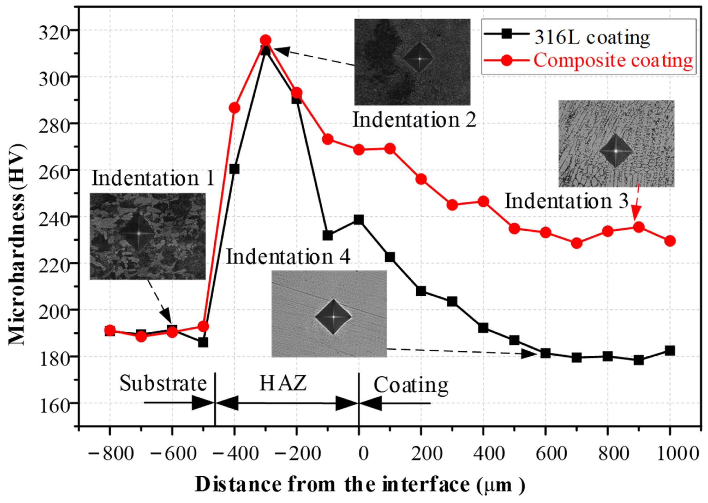
3.3. Microhardness of Coatings

Figure 5 indicates the microhardness distribution of the 316L coating and the composite coating along the building direction. The results show that the microhardness of the 316L coating and the composite coating follows the same trend from the bottom to the top of the coating. It gradually decreases along the direction of coating growth and eventually tends to a stable value. The average microhardness of the fabricated 316 coatings is 181.14 ± 2.77 HV, which is consistent with existing research results [29]. When 10 wt% TiC and 10 wt% NbC ceramic particles are added, the microhardness of the composite coating is 232.12 ± 2.91 HV, which is 1.28 times that of the 316L coating. The increase in hardness of the composite coating is the result of grain refining and solution strengthening. As shown in Figure 5, fine hard particles are distributed near indentation 4. These high hardness TiC (32 GPa) and NbC (24.1 GPa) act as a frame, weakening the grain dislocation and inhibiting the deformation of the composite coating. In addition, the microstructure analysis shows that TiC and NbC can refine the grains of the composite coating, resulting in the improvement of plastic deformation resistance. Interestingly, the microhardness of the 316L and composite coatings decreases with the deposition height. As the number of deposited layers increases, heat accumulation results in a gradual increase in the maximum temperature of the melt pool. As a result, the previous deposition layer was subjected to a tempering heat treatment, which led to a gradual decrease in microhardness [30]. However, the high density of NbC particles (7.56 g/cm3) tends to be more distributed at the bottom of the single track under the effect of strong Marangoni convection, resulting in the high microhardness at the bottom of the coating [16]. The material on top of the coating would be removed during subsequent machining, so the characteristics of the microhardness distribution are beneficial to improve the practical application of the coating. Therefore, it should be noted that the maximum microhardness in the heat-affected zone is 315 HV. According to the microstructure near Indentation 2, the acicular martensite is generated due to rapid cooling, which effectively improves the microhardness. With the increase in the test depth, the cooling rate of the substrate decreases gradually. Therefore, the acicular martensite was gradually transformed into lamellar martensite. The microhardness of the substrate decreased gradually, and finally approached the microhardness value of 45 steel 190.08 ± 2.11 HV.

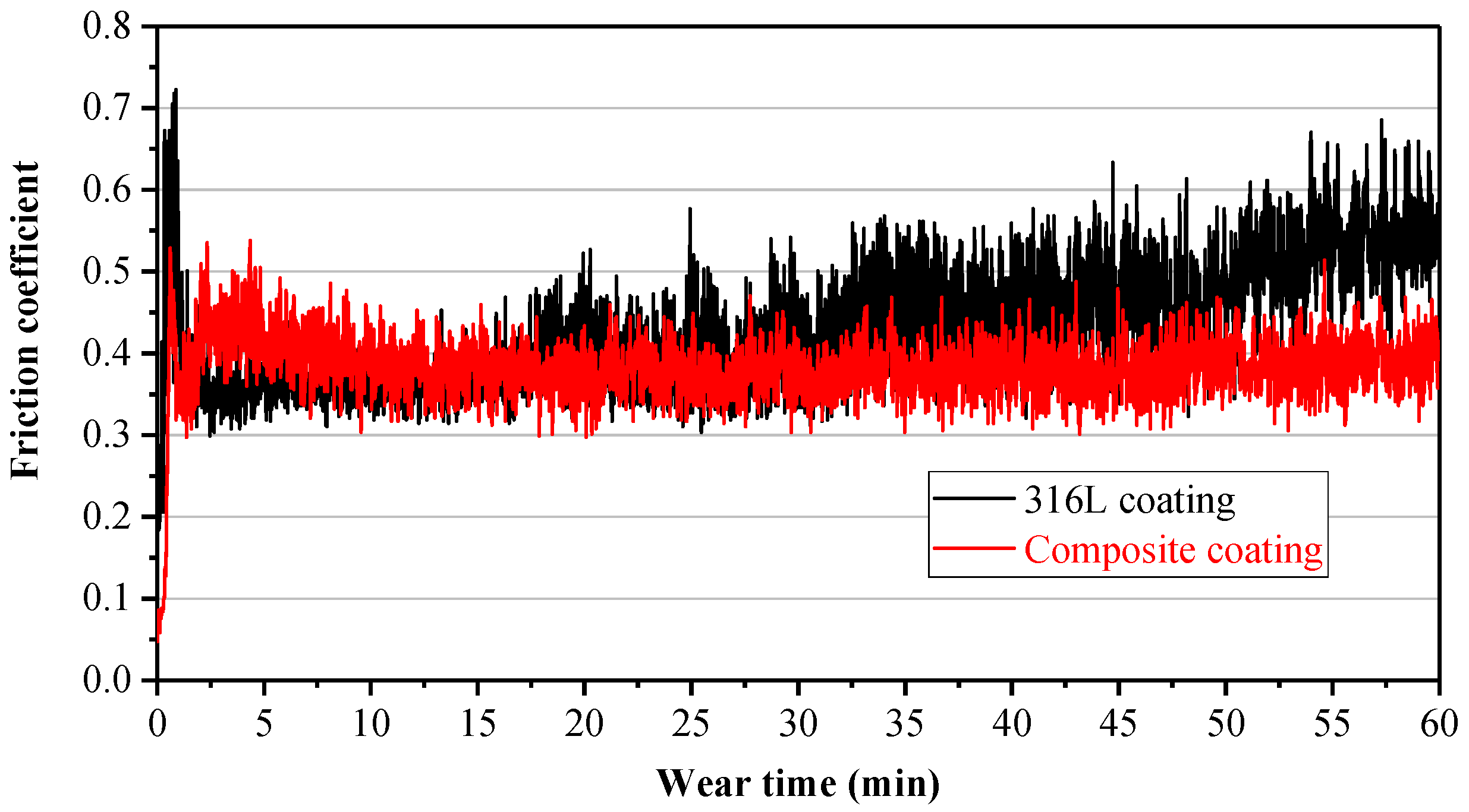
3.4. Wear Performance

To analyze the addition of TiC and NbC particles on the wear resistance and reveal the wear mechanism, the friction coefficient, wear volume, 2D and 3D worn surfaces of each coating, and wear ball were obtained and analyzed. The test was conducted on a multi-functional surface performance tester (MFT-4000). The variation of the friction coefficient of the 316L coating and the composite coating with sliding time is shown in Figure 6. It is noted that the friction coefficients of the two coatings had similar trends over time. In the initial friction stage, the friction coefficient fluctuated greatly because of the small contact area between the GCr15 ball and the coating. In addition, the friction coefficient of the composite coating was more stable than that of the 316L coating. As the coating material was gradually removed, the friction coefficient of the coating stabilized after about 20 min. The friction coefficient of the 316L coating was 0.451 ± 0.075 in the stable stage. The friction coefficient of the composite coating decreased to 0.381 ± 0.030 due to the addition of TiC and NbC particles, which was 0.846 times that of the 316L coating. The 3D worn surfaces of the 316L coating and the composite coating are shown in Figure 7. Large plastic deformation can be found at the edges of the wear tracks of the two coatings, which indicates that both coatings provide good toughness. However, the depth and width of the wear tracks of the composite coating were smaller than those of the 316L coating. The cross-sectional area of the 316 coating and the composite coating after wear were also measured with 3D laser microscopy. The cross-sectional area of 316 coatings was 13,540.933 μm2. When TiC and NbC particles were added to the 316L alloy, the cross-sectional area of composite coating was 8164.732 μm2, which was 0.603 times that of the 316L coating. The results show that TiC and NbC ceramic particles can effectively reduce the wear rate of the 316L coating.
To further reveal the wear mechanism of each coating, 2D and 3D magnified morphologies of the worn surfaces of the 316L and composite coatings were obtained, as shown in Figure 8. Obvious plastic deformation is observed on the worn surface of the 316L coating (see Figure 8a), and large grooves were generated along the sliding direction. When the GCr15 ball reciprocates on the surface of the 316L coating with low microhardness, it results in high local contact pressure. As a result, the material on the surface was removed by extrusion, deformation, and shearing. These tough abrasive chips are prone to adhere to the surface of the GCr15, leading to adhesive wear of the 316L coating. Therefore, the wear mechanism of the 316L coating is mainly severe plastic deformation and adhesive wear. Figure 8b indicates that no deep grooves were found on the worn surface of the composite coating. Some pits and smooth areas appeared alternately due to the peeling of the material. According to the Archard wear model, the wear resistance of materials is proportional to their microhardness [31]. These results indicate that TiC and NbC particles play an important role in preventing plastic deformation and the shear removal of composite coatings. At the initial stage of wear, the matrix material with lower microhardness was removed first. As the wear progressed, TiC and NbC hard ceramic particles in the composite coating were exposed to contact with the GCr15 ball gradually, which plays a role in the frame and reduces the removal of the matrix. At the same time, the fine grain strengthening effect leads the material to have good toughness and increases the bonding force between the ceramic particles and matrix. Therefore, the peeling of ceramic particles is decreased, and the wear resistance of the coating is improved. From the above analysis, slight abrasive wear and adhesive wear together generated the worn surface characteristic of the composite coating.
Figure 9 shows the 2D and 3D morphology of the GCr15 ball after wearing the 316L and composite coatings. According to Figure 9a1, it can be found that the GCr15 ball had severe wear in the process of wearing the 316L coating. No significant wear was observed on the GCr15 sphere after wear despite the high microhardness of the composite coating. Figure 9a1 shows that the chips formed by the 316L coating were not attached to the worn surface. This indicates that the GCr15 ball was in direct contact with the matrix of the 316L coating, which accelerated the material removal of the GCr15 ball. However, a large number of small chips were found on the surface of the composite coating after wear (Figure 9b2). This was because the small chips were not discharged from the wear track in time. These abrasive chips, which contain element C, provide a lubrication effect during the wear process [32]. Therefore, the wear rate of the composite coating and GCr15 ball was decreased, as shown in Figure 9b.

4. Conclusions

In this study, to improve the microhardness and wear resistance of 316L stainless steel, fine TiC and NbC ceramic particles were introduced into 316L powders to fabricate the composite coating by powder-fed laser cladding. The phase composition, microstructure, microhardness, and wear properties of the 316L coating and the composite coating are compared and discussed in detail. The main conclusions are as follows:
  • The TiC and NbC ceramic particles with low thermal conductivity were mainly located at the grain boundary, effectively inhibiting grain growth, increasing nucleation sites, and refining grains. The introduction of ceramic particles decreased the temperature gradient in the melt pool and promoted the transformation of coarse columnar crystals to fine equiaxed crystals, improving the metallurgical bonding properties of the composite coating to the substrate.
  • The microhardness of the composite coating was 232.12 ± 2.91hV, which was 1.28 times that of the 316L coating. The increase in microhardness was a combination of fine grain strengthening and solution strengthening.
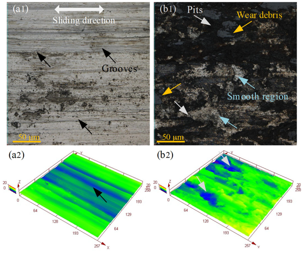
  • The friction coefficient and wear cross-sectional area of the composite coating were 0.381 and 8164.732 μm2, which were 0.846 and 0.603 times that of the 316L coating, respectively. The wear mechanism changed from severe adhesive wear and plastic deformation to slight adhesive wear and abrasive wear due to the addition of TiC and NbC ceramic particles.
  • During the wear process, the removal rate of the composite coating and the grinding balls decreased due to the lubrication of the fine abrasive chips.
Overall, this work presents a method for improving the wear resistance of 316L stainless steel by laser cladding. However, it was also found that the microhardness distribution of the fabricated coatings is not uniform. Therefore, we plan to design an ultrasound-assisted laser cladding system to improve the mechanical properties of the coating. In addition, the mechanical machinability of the composite coatings is also the focus of future work.

Author Contributions

J.Y.: conceptualization, methodology, testing, analysis, data curation, writing—original draft, writing—review, and editing. H.H.: supervision, funding acquisition, analysis of the results, and project administration. All authors have read and agreed to the published version of the manuscript.

Funding

This work was supported by the National Natural Science Foundation of China [No. 51650110502].

Institutional Review Board Statement

Not applicable.

Informed Consent Statement

Not applicable.

Data Availability Statement

The datasets supporting the conclusion of this article are included within the article.

Conflicts of Interest

The authors declare no conflict of interests.

References

  1. Akbari, M.; Kovacevic, R. An investigation on mechanical and microstructural properties of 316LSi parts fabricated by a robotized laser/wire direct metal deposition system. Addit. Manuf. 2018, 23, 487–497. [Google Scholar] [CrossRef]
  2. Zhan, M.J.; Sun, G.F.; Wang, Z.D.; Shen, X.T.; Yan, Y.; Ni, Z.H. Numerical and experimental investigation on laser metal deposition as repair technology for 316L stainless steel. Opt. Laser Technol. 2019, 118, 84–92. [Google Scholar] [CrossRef]
  3. Junior, W.N.; Naeem, M.; Costa, T.H.C.; Díaz-Guillén, J.C.; Díaz-Guillén, M.R.; Iqbal, J.; Jelani, M.; Sousa, R.R.M. Surface modification of AISI-304 steel by ZnO synthesis using cathodic cage plasma deposition. Mater. Res. Express 2021, 8, 096403. [Google Scholar] [CrossRef]
  4. Sun, G.F.; Shen, X.T.; Wang, Z.D.; Zhan, M.J.; Yao, S.; Zhou, R.; Ni, Z.H. Laser metal deposition as repair technology for 316L stainless steel: Influence of feeding powder compositions on microstructure and mechanical properties. Opt. Laser Technol. 2019, 109, 71–83. [Google Scholar] [CrossRef]
  5. De Lima, M.S.F.; Sankaré, S. Microstructure and mechanical behavior of laser additive manufactured AISI 316 stainless steel stringers. Mater. Des. 2014, 55, 526–532. [Google Scholar] [CrossRef]
  6. Chen, L.; Yu, T.; Xu, P.; Zhang, B. In-situ NbC reinforced Fe-based coating by laser cladding: Simulation and experiment. Surf. Coat. Technol. 2021, 412, 127027. [Google Scholar] [CrossRef]
  7. Lo, K.H.; Cheng, F.T.; Kwok, C.T.; Man, H.C. Improvement of cavitation erosion resistance of AISI 316 stainless steel by laser surface alloying using fine WC powder. Surf. Coatings Technol. 2003, 165, 258–267. [Google Scholar] [CrossRef]
  8. Jelani, M.; Li, Z.; Shen, Z.; Hassan, N.U.; Sardar, M. Mechanical response and failure evolution of 304L stainless steel under the combined action of mechanical loading and laser heating. Metals 2018, 8, 620. [Google Scholar] [CrossRef] [Green Version]
  9. Fathi, R.; Wei, H.; Saleh, B.; Radhika, N.; Jiang, J.; Ma, A.; Ahmed, M.H.; Li, Q.; Ostrikov, K.K. Past and present of functionally graded coatings: Advancements and future challenges. Appl. Mater. Today 2022, 26, 101373. [Google Scholar] [CrossRef]
  10. Zhou, W.L.; Lv, C.; Li, Y.; Ho, H. Effect of Shot Peening Intensity on Surface Integrity and Fatigue Life of 316 Stainless Steel. Surf. Technol. 2020, 49, 230–237. [Google Scholar]
  11. Peng, Y.W.; Liu, Z.; Gong, J.M. Rotating bending fatigure characteristics and residual stress stability of Low-temperature gas carburized 316L autenitic stainless steel. In Proceedings of the 10th National Academic Conference on Pressure Vessels, Hangzhou, China, 26–29 September 2021. [Google Scholar]
  12. Li, G.Y.; Liu, J.D.; Wang, X.; Zheng, F.L.; Shi, B.; Li, G.Y. Plasma source nitriding for 316L austenitic stainless steel. Heat Treatment. 2018, 33, 44–48. [Google Scholar]
  13. Naeem, M.; Awan, S.; Shafiq, M.; Raza, H.A.; Iqbal, J.; Díaz-Guillén, J.C.; Sousa, R.R.M.; Jelani, M.; Abrar, M. Wear and corrosion studies of duplex surface-treated AISI-304 steel by a combination of cathodic cage plasma nitriding and PVD-TiN coating. Ceram. Int. 2022, 48, 21473–21482. [Google Scholar] [CrossRef]
  14. Chen, L.; Zhao, Y.; Chen, X.; Yu, T.; Xu, P. Repair of spline shaft by laser-cladding coarse TiC reinforced Ni-based coating: Process, microstructure and properties. Ceram. Int. 2021, 47, 30113–30128. [Google Scholar] [CrossRef]
  15. Zhu, L.; Xue, P.; Lan, Q.; Meng, G.; Ren, Y.; Yang, Z.; Xu, P.; Liu, Z. Recent research and development status of laser cladding: A review. Opt. Laser Technol. 2021, 138, 106915. [Google Scholar] [CrossRef]
  16. Zhao, Y.; Chen, L.; Sun, J.; Wu, W.; Yu, T. Microstructure evolution and wear resistance of in-situ synthesized (Ti, Nb)C ceramic reinforced Ni204 composite coatings. Ceram. Int. 2022, 48, 17518–17528. [Google Scholar] [CrossRef]
  17. Yu, J.; Ho, H.; Chen, J. Effect of Ti content on the microstructure and mechanical properties of laser clad Ti/B4C/dr40-based composite coatings on shaft parts surface. Ceram. Int. 2022, 48, 13551–13562. [Google Scholar] [CrossRef]
  18. Zhao, Y.H.; Gao, M.Q.; Zhao, J.B.; He, C. Microstructure and Properties of WC Particles Reinforced 316L Stainless Steel Composites Prepared by Additive and Subtractive Manufacturing. Dongbei Daxue Xuebao J. Northeast. Univ. 2022, 43, 197–205. [Google Scholar] [CrossRef]
  19. AlMangour, B.; Grzesiak, D.; Cheng, J.; Ertas, Y. Thermal behavior of the molten pool, microstructural evolution, and tribological performance during selective laser melting of TiC/316L stainless steel nanocomposites: Experimental and simulation methods. J. Mater. Process. Technol. 2018, 257, 288–301. [Google Scholar] [CrossRef]
  20. Pei, D.; Deng, P.Y.; Liu, Z.J.; Wang, L. Preparation and Property Evaluation of NbC Coating Deposited on 316 L Stainless Steel. Surf. Technol. 2019, 48, 105–111. [Google Scholar]
  21. Cheng, Q.; Chen, H.; Hou, Y.; Xu, Y.; Fan, L.; Dong, L. Microstructure and wear behavior of spherical NbC hardmetals with nickel-based binders on AISI 4145H steel. Int. J. Refract. Met. Hard Mater. 2021, 95, 105414. [Google Scholar] [CrossRef]
  22. Li, Q.; Lei, Y.; Fu, H. Growth mechanism, distribution characteristics and reinforcing behavior of (Ti, Nb)C particle in laser cladded Fe-based composite coating. Appl. Surf. Sci. 2014, 316, 610–616. [Google Scholar] [CrossRef]
  23. Zhao, Y.; Chen, L.; Sun, J.; Yu, T. Mechanical property of YCF101 coating under different overlap modes by laser cladding. Optik 2020, 212, 164714. [Google Scholar] [CrossRef]
  24. Zhang, K.; Wang, S.; Liu, W.; Shang, X. Characterization of stainless steel parts by Laser Metal Deposition Shaping. Mater. Des. 2014, 55, 104–119. [Google Scholar] [CrossRef]
  25. Lenart, R.; Eshraghi, M. Modeling columnar to equiaxed transition in directional solidification of Inconel 718 alloy. Comput. Mater. Sci. 2020, 172, 109374. [Google Scholar] [CrossRef]
  26. Chen, L.; Zhao, Y.; Song, B.; Yu, T.; Liu, Z. Modeling and simulation of 3D geometry prediction and dynamic solidification behavior of Fe-based coatings by laser cladding. Opt. Laser Technol. 2021, 139, 107009. [Google Scholar] [CrossRef]
  27. Gan, Z.; Yu, G.; He, X.; Li, S. Numerical simulation of thermal behavior and multicomponent mass transfer in direct laser deposition of Co-base alloy on steel. Int. J. Heat Mass Transf. 2017, 104, 28–38. [Google Scholar] [CrossRef] [Green Version]
  28. Tong, Z.; Ren, X.; Jiao, J.; Zhou, W.; Ren, Y.; Ye, Y.; Larson, E.A.; Gu, J. Laser additive manufacturing of FeCrCoMnNi high-entropy alloy: Effect of heat treatment on microstructure, residual stress and mechanical property. J. Alloys Compd. 2019, 785, 1144–1159. [Google Scholar] [CrossRef]
  29. Guo, P.; Zou, B.; Huang, C.; Gao, H. Journal of Materials Processing Technology Study on microstructure, mechanical properties and machinability of efficiently additive manufactured AISI 316L stainless steel by high-power direct laser deposition. J. Mater. Process. Technol. 2017, 240, 12–22. [Google Scholar] [CrossRef]
  30. Chen, L.; Yu, T.; Guan, C.; Zhao, Y. Microstructure and properties of metal parts remanufactured by laser cladding TiC and TiB2 reinforced Fe-based coatings. Ceram. Int. 2022, 48, 14127–14140. [Google Scholar] [CrossRef]
  31. Guo, Y.; Li, C.; Zeng, M.; Wang, J.; Deng, P.; Wang, Y. In-situ TiC reinforced CoCrCuFeNiSi0.2 high-entropy alloy coatings designed for enhanced wear performance by laser cladding. Mater. Chem. Phys. 2020, 242, 122522. [Google Scholar] [CrossRef]
  32. Ferreira, D.F.S.; Vieira, J.S.; Rodrigues, S.P.; Miranda, G.; Oliveira, F.J.; Oliveira, J.M. Dry sliding wear and mechanical behaviour of selective laser melting processed 18Ni300 and H13 steels for moulds. Wear 2022, 488–489, 204179. [Google Scholar] [CrossRef]
Figure 1. Laser cladding process and test characterization.
Applsci 12 06684 g001
Figure 2. XRD results of 316L coating and composite coating.
Applsci 12 06684 g002
Figure 3. Optical microstructures: (a1a3) 316L coating and (b1b3) composite coating.
Applsci 12 06684 g003
Figure 4. (a) SEM image, and (bh) mapping of C, Ti, Nb, Fe, Mo, Cr, and Si elements of the composite coating.
Applsci 12 06684 g004
Figure 5. Microhardness distribution of 316L and composite coatings along building direction.
Applsci 12 06684 g005
Figure 6. Friction coefficient of 316L coating and composite coating.
Applsci 12 06684 g006
Figure 7. Three-dimensional wear morphology and sectional wear area: (a1,a2) 316L coating and (b1,b2) composite coating.
Applsci 12 06684 g007
Figure 8. Magnified 2D and 3D worn morphology: (a1,a2) 316L coating and (b1,b2) composite coating.
Applsci 12 06684 g008
Figure 9. Optical and 3D morphology of the GCr15 ball after wear test: (a1a3) for 316L coating and (b1b3) for composite coating.
Applsci 12 06684 g009
Table 1. Chemical composition of 316L and substrate (wt%).
CrMoMnSiCPCuNiFe
316L18.622.531.350.540.030-12.72Bal.
45 steel0.2-0.10.270.45≤0.035≤0.250.03Bal.
Table 2. Optimal process parameters for four-layer coating by laser cladding.
Laser PowerScanning SpeedPowder Feed RateTrack SpaceZ-Axis Increment
380 W5.5 mm/s0.8 r/min0.8 mm0.3 mm
Table 3. EDS results for each region in Figure 4 (at.%).
RegionsCSiTiCrMnFeNiNbMo
P114.741.42-15.281.6856.309.55-1.03
P237.880.731.609.331.1821.013.2023.231.84
P326.421.771.7313.071.9622.648.2122.341.86
P424.501.1727.1612.831.4922.456.832.600.97
P522.891.2728.2712.821.2622.606.873.140.88
Publisher’s Note: MDPI stays neutral with regard to jurisdictional claims in published maps and institutional affiliations.

