Abstract
The article provides brief information about a non-standard experimental setup developed in the laboratory of the St. Petersburg Mining University Well Drilling Department. The developed technique presented makes it possible to simulate well cleaning process of cuttings by incorporating the variation of the parameters (the zenith angle of the well, the volume flow and rheological properties of the cleaning agent, the rotation frequency, the number and length of the drill string half-waves) that cause buckling. For the first time, the positive side of the drill string (DS) buckling phenomenon is considered. A positive hydro-mechanical effect on mud plugs and improved well cleaning were revealed. The results of the experimental study confirm an intense difficulty in transporting cuttings to the surface at a critical zenith angle of the well of 55°. Regularities have been established making it possible to determine the effect of DS buckling on the cutting-carrying capacity when drilling deviated and extended reach wells. It is proposed to use hydromechanical impact on the accumulated cuttings by artificially controlling the resulting DS buckling in order to destroy the mud plug and increase the efficiency of well cleaning without the use of specialized devices. A conceptual solution aimed at implementing a method for hydromechanical destruction of mud plugs—the use of drill pipes equipped with a quasi-distributed differential measuring system of strain gauges based on a fiber-optic Bragg grating—is presented.
1. Introduction
Every year, the share of directional drilling around the world is increasing and today it is about 85% of the total volume of oil and gas wells [1,2]. This is due to the development of hard-to-reach and deep-lying reservoirs, access to which is possible only through long wells of complex trajectories, which have a large number of areas of change in zenith and azimuth angles. Consequently, the likelihood of complications and accidents increases, which in most cases are associated with poor-quality well cleaning of drill cuttings (mud) [3,4]. Poor cleaning at the well of cuttings leads to their accumulation at the bottom wall and the formation of the so-called “mud dunes” or “mud pads”, which affect the drilling tool and hydrodynamic pressure, increasing the equivalent circulation density (ECD) of the drilling fluid (DF) [5,6,7]. With a local increase in the concentration of cuttings, the annular space between the drill string (DS) and the walls of the well can become completely clogged and form a “mud plug”, which leads to the risk of complications and accidents associated with the operation of the tool in the well, rock stability [8,9,10] and reservoir properties.
Improving the quality of well cleaning from drill cuttings is an important task when drilling directional and, especially, horizontal wells, which can be achieved through the use of special technical means and technological methods. One of these technological methods is the operational control and management of drilling parameters, the essence of which is the timely regulation of key parameters: DS rotation speed, flow rate and axial load on bit. An increase in the flow rate leads to an increase in the upward flow velocity in the annular space and an improvement in well cleaning [11]. The dynamic component of the ECD strongly depends on the consumption of drilling mud. However, it is impossible to improve cleaning by increasing the consumption of mud alone, especially under conditions of a narrow range of fluid loss and kick pressures [12]. Increasing the rotation speed of the DS has a hydrodynamic effect on the cuttings, creating a circumferential flow that does not carry particles out of the well, but has a “turbulent” effect, which contributes to the removal of particles from stagnant zones [13,14]. It has been empirically established that an increase in the rotational speed of the DS to 140 rpm has a positive effect on the quality of cleaning, and a subsequent increase in the rotational speed has practically no effect on the removal of mud. A significant increase in the rotation frequency of the bottom hole assembly (BHA) can have a negative impact on the elements of the BHA, such as reactive torque increase—twists-off, increase vibrations and beats—irreversible deformations and breaks-off. The use of special technical means that are part of the DS and improve well cleaning [15,16,17], such as turbulators, circulating subs, etc., do not obtain the desired effect, due to the complexity of the trajectories, limitations in the number of installed devices, vugular porosity and rock stability. In oil production, there were situations when the presence of turbulators had a negative effect—the reactive twisting moment increased, and the area of the annular space decreased, which led to an increase in hydraulic shocks and an increase in ECD [16]. The rheology of the mud is one of the factors that have a significant impact on the cleaning of deviated wells, ECD and the state of the bottomhole zone [18,19]. Undoubtedly, mud chemical treatment makes it possible to increase the efficiency of well cleaning and prevent technological complications in the drilling process. However, there are risks of contamination of the oil and gas saturated formation [20], and the selection of complex rheological profiles for drilling with a complex trajectory in specific geological and technical conditions requires significant financial costs.
The increase in drilling speed is affected by the axial load on the bit, as well as the quantity and quality of mud, which must promptly clean the bottomhole from cuttings during drilling. The axial load applied to the entire area of contact with the drilling tool must exceed the strength of the rock and break it down. However, it is known that in directional wells, and especially in wells with complex profiles and large deviations from the vertical, the axial load applied to the bit does not reach the bottom hole in full [14,21]. This is due to the complex stress–strain state of the drilling tool in cramped downhole conditions. The initial increase in the axial load that does not reach the bottom leads to the loss of the longitudinal stability of the DS and the acquisition of the shape of a sinusoid—a bend of the first kind (sinusoidal buckling) is formed. With a subsequent increase in the load, the DS takes the form of a spiral—a bend of the second kind (spiral buckling) is formed [22]. Longitudinal loss of stability of the drilling tool contributes to the occurrence of lapels and fractures of the drilling tool. In drilling practice, engineers try to avoid situations in which the DS loses its stability and takes any form of buckling [14,21,22,23]. However, the positive effects of artificially created and controlled buckling of the DS on the destruction of mud plugs and cleaning the well from cuttings are proposed in this paper.
Medium- and large-scale full-scale modeling of drilling and well cleaning processes in the laboratory is being carried out by many researchers, both in Russia and abroad. Experiments carried out at M-I SWACO (USA) are considered to be particularly significant studies that have found wide application in the practice of drilling wells. The results of the research were presented in 2001 as a guide for drilling fluid engineers. Scientists have determined the critical zenith angles (range 45–60°) at which cuttings particles are insufficiently carried out of the well. Many other factors influencing well cleaning were analyzed, and recommendations were made for the construction of wells of various trajectories. In 2012, Malaysian researchers conducted full-scale experiments to study the effect of mud viscosity and velocity, as well as the zenith angle, on the transport of drilled particles in deviated and horizontal wells [24]. In 2016, Iranian researchers developed an experimental stand and published the results of studies [25] on the influence of the zenith angle, the speed of the DS, the consumption of DF and the cuttings fraction on the cleaning of an inclined well. In 2019, an employee of RN-Vankor published the results of a study of the effect of DS rotation on cuttings transport in a horizontal well, obtained on a small-scale experimental bench. The influence of DS rotation on mud transport was confirmed, as well as a decrease in the “turbulent effect” with an increase in DF viscosity [13]. In 2018–2019 a group of international researchers published the results of the effect of rotation of the DF on cleaning the well with the use of polypropylene particles in DF at different zenith angles [26,27,28]. In 2020–2021 a group of Norwegian scientists published the results [29,30] of hydraulic studies and mud transport with oil-based solutions in deviated wells, using a large-scale laboratory facility developed with the support of Aker BP and M-I SWACO. The above studies confirmed the presence of critical zenith angles of the well trajectory, described the effect of the rotation speed of the drilling rig, volumetric flow, technological and mud rheological properties on the quality of wellbore cleaning of cuttings. However, the effect of DS buckling on the destruction of mud plugs and mud carryover has not been addressed in any of the above works, due to the fact that engineers are trying to predict and exclude the buckling phenomenon [21,31,32,33], and the positive effect of controlled DS buckling on well cleaning has hardly been considered.
The purpose of the study is to determine the effect of DS buckling on the breakdown of mud plugs and the cleaning of deviated wells from cuttings, taking into account drilling parameters, zenith angle and mud properties. To achieve this goal, two series of applied field studies were carried out using muds with different rheological models. The development of a technology to improve the quality of well cleaning, which is based on the operational control and management of the number and lengths of half-waves of DS and their hydromechanical effect on mud plugs, taking into account the drilling parameters, zenith angle and mud properties, will improve the efficiency of the construction of directional wells.
The present study includes the determination of DS spatial shape influence on the sludge plugs’ destruction and deviated wells cleaning from cuttings. The main idea of the study is not to fight against DS buckling, as a negative effect that one way or another occurs when drilling wells with long or complex trajectories, but to use this phenomenon to advantage—to control and manage buckling, artificially creating DS bends in places where cuttings accumulate.
2. Materials and Methods
The study of the effect of DS buckling on the breakdown of mud plugs and well cleaning was carried out on a specially designed experimental stand in the laboratory of St. Petersburg Mining University Well Drilling Department [34]. The stand has a closed circulation system and allows modeling of the process of destruction of the mud plug and transport of mud from the well, taking into account the zenith angle, rotational speed, number and length of half-waves string with longitudinal buckling, as well as the mud flow rate, its rheological properties and the mud fraction. The main characteristics and composition of the experimental stand are shown in Figure 1 and in Table 1.
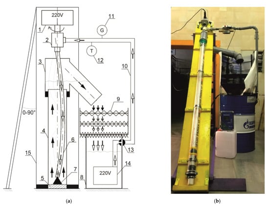
Figure 1.
Schematic (a) and photo (b) of the experimental stand: 1—drive, 2—swivel, 3—wellhead equipment, 4—wellbore, 5—plug, 6—drill pipes, 7—support cone, 8–mud tank, 9—sieve cleaning unit, 10—discharge line, 11—ultrasonic flowmeter, 12—laser tachometer, 13—mudflow controller, 14—pump.

Table 1.
Main technical characteristics of the experimental stand.
The experimental studies are carried out according to the developed algorithm. A drilling fluid with required composition and quantity is prepared in a tank 8, a sieve cleaning unit 9 is installed on top, in which, depending on the selected cuttings fraction, a sieve with a particular mesh size is installed. The wellhead pipe 3 is connected to the upper part of the “wellbore” pipe 4 installed on the base 15, and the plug 5 is installed in the lower part of the pipe 4. The pipe DS 6 with the selected number of half-waves is installed at the lower end (with holes and a rubber seal) into the pipe 4 on the support cone 7, through the “mouth head” 3, and is connected by a threaded connection to the transit swivel 2, which is connected to the drive 1. The end of the discharge line 10, connected to the swivel, is made of a metal pipe, on which a laser tachometer is installed 12 and ultrasonic flow meter 11, the principle of which is based on the Doppler effect. A reflective element is attached to the lower part of the swivel shaft 2, which is necessary for measuring the DS speed with a laser tachometer 12. The discharge line 10 is connected to the flow controller 13, which is fixed in the tank 8. The pump 14 is installed at the bottom of the tank 8 and connected to the flow controller 13. The slurry of the required amount is poured into the annular space between pipes 4 and 6 through the mouth head 3.
The input parameters of the experiments are presented in Table 2.
Table 2.
The input parameters of the experiments.
The experimental stand is set at the required zenith angle. The pipe 6 with the selected number of half-waves (straight pipe L0 without half-waves, pipe with the 1st half-wave L1 = 1.8 m pipe with 3 half-waves L3 = 0.6 m) is installed on the support cone 7 in the pipe 4 “wellbore”. Mud weighing m = 1.5 kg fraction 1.0 ÷ 2.0 mm is poured into the annular space between pipes 4 and 6. Pump 14 pumps DF at a flow rate of Q (L/min), regulated by the flow controller 13. The value of the mud flow is displayed on display of the control unit of the acoustic flowmeter 11. Next, the drive is turned on, which rotates the pipe with a frequency of n (rpm), the value of which is displayed on the display of the laser tachometer 12. The time allotted for 1 experiment, within the framework of a series of experiments, t = 120 s. During this time, the “borehole” is cleaned of accumulated mud on the sieves of the corresponding fraction in the cleaning unit 9. After the time has elapsed, the pump and drive are turned off, the sieves are removed and cleaned of mud, which is weighed on electronic scales. Change of pipe with a different number and lengths of half-waves is carried out by disconnecting the swivel from the drive and pipe, with its subsequent extraction from the “borehole”. After a series of experiments (No. 1), the mud is disposed of, the circulation system is completely flushed for 10 min, another type of mud is prepared in the tank, and a series of experiments (No. 2) is carried out according to the above algorithm.
The design of the experimental stand was based on the principle of geometric similarity (1):
where is the diameter of a real wellbore, mm; is the diameter of the real string, mm; —diameter of the experimental “wellbore”, mm; is the diameter of the experimental string, mm; and C is the coefficient of proportionality or “constant of geometric similarity”.
DS deflection (wave amplitude) in the experimental stand (2) is represented as:
In order to determine the effect of buckling on the destruction of mud plugs and well cleaning of cuttings particles, it was necessary to obtain an artificial buckling of the DS. At this stage of research, it was decided to abandon the creation of a system for smooth artificial regulation of the number of half-waves strings in favor of a simplified discrete system, due to the lack of knowledge of this drilling area and the need to test the hypothesis put forward. The half-waves strings were obtained by heating the pipes and subsequent irreversible bending deformation, while maintaining the diameter along the entire length. Thus, the pipes with 1st and 3rd half-waves were obtained, equal to the length of the well.
3. Results
3.1. General Research Results
In addition to comparing the experimental data on the effect of buckling on the removal of cuttings, it was possible to evaluate the process of breakdown of the mud plugs in directional sections of the well visually (Figure 2) due to the transparency of the “wellbore” pipe.
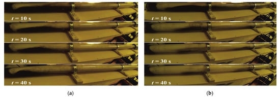
Figure 2.
Temporal collage of photographs of experiments with mud No. 2 at α = 70°, Q = 1.25 × 10⁻³ m3/s, rotation with a frequency of n = 1.67 s−1, direct pipe L0 (a) and pipe with 3 half-waves L3 (b).
To assess the effectiveness of the hydromechanical process of breakdown of mud plugs, which is in a state of buckling of the first kind, as well as to assess the quality of well cleaning from cuttings, it is necessary to fix the mass of fractional sand poured into the experimental stand. Through test measurements, it was found that under the given geometric and temporal conditions, the mass of sand m = 1.5 kg can be taken as a unit. However, in the course of experimental studies, it was found that, in some cases, it is impossible to assess the quality of well cleaning, due to the complete removal of cuttings ahead of the allocated time, and t = 120 s due to certain combinations of values of variable parameters. For this reason, the number of cuttings cleaned out was recalculated in time and the well cleaning intensity was obtained: for series of experiments No. 1, the time t1 = 30 s, and for series of experiments No. 2, the time t2 = 60 s.
The initial and time-recalculated results of the mud removal intensity, using the example of a Newtonian fluid at a zenith angle α = 35°, are shown in Figure 3. It can be seen from the graphs that when L3 rotates a flat-curved pipe with three half-waves (blue lines) at a frequency of n = 2.5 s−1, the quality of wellbore cleaning increases significantly compared to L0 of a straight pipe (yellow lines), with a changing mud consumption, Q within the range of 1.25 ÷ 1.67 × 10⁻³ m3/s.
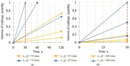
Figure 3.
Initial (a) and recalculated (b) rates of mud removal at α = 35°, DF No. 1, Q = 75 ÷100 L/min and rotation at a frequency of n = 2.5 s−1 direct pipe L0 and DS with 3 half-waves L3.
The recalculation of the removal of mud cuttings over time made it possible to obtain values for the subsequent assessment of the process of hydromechanical breakdown of the drilling mud plugs, which is in a state of buckling of the first kind, and the quality of well cleaning. The data obtained as a result of experimental studies can be interpreted both on a plane, in two-dimensional space, and in three-dimensional space, in the form of surfaces, depending on the number of fixed variables. For each case of interpretation, mathematical models were obtained—regression equations with correlation coefficients (Figure 4, Table 3). A total of 54 mathematical models have been obtained that describe the change in the quality of well cleaning from cuttings particles depending on variable parameters. For processing the results of experiments, correlation-regression and variance analyzes, “Statistica 13” and “MS Office Excel 2016” software were used.
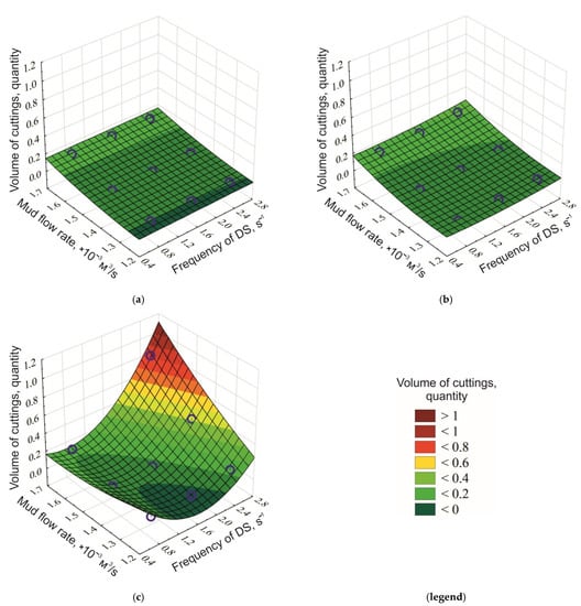
Figure 4.
Dependence of the amount of mud carried out (fraction of units) during the destruction of the mud plug on the DF No. 1 consumption, the rotational speed and the number of half-waves pipes: without half-waves (a); with the 1st half-wave (b) and with the 3rd half-waves (c), at the zenith angle α = const = 70°.
Table 3.
Mathematical models of dependencies presented in Figure 4.
Analyzing the obtained mathematical models presented in Table 3, the coefficient characterizing the strength of the influence of factors on each other can be seen: with a direct pipe = 0.0112; at the 1st half-wave = 0.0449; with 3 half-waves = 0.8348. This allows us to conclude that the mutual influence of the factors of the speed of rotation of the pipe and the mud consumption on each other increases, as a result of the loss of stability of the pipe and the subsequent acquisition of a sinusoidal shape.
At the maximum flow rate of mud No. 1 Q = 1.67 × 10⁻³ m3/s, a decrease in the mud carried out on the sieves is observed, in comparison with washing at the average flow rate Q = 1.45 ×·10−3 m3/s, at a maximum constant frequency n = 2.50 s−1. This observation allows us to conclude that an increase in the drill speed does not always improve the removal of cuttings.
Experimental data reflecting the effect of pipe buckling at a rotation frequency of n = 2.5 s−1, as well as the zenith angle, flow rate, technological and rheological properties of DF on the destruction of mud plugs and well cleaning, are shown in Figure 5 in the form of histograms, convenient for comparison.
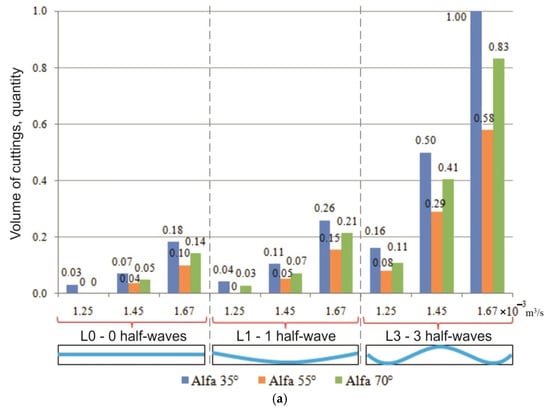
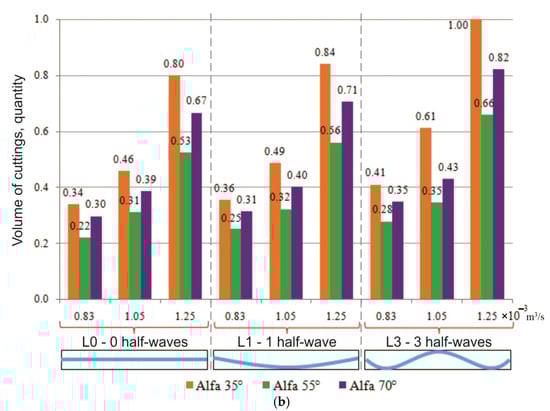
Figure 5.
Removed cuttings from mud #1 (a) and mud #2 (b) depending on the sinusoidal pipe buckling, zenith angle, flow rate, and mud properties at a constant rotational speed n = 2.5 s−1.
3.2. Influence of the Zenith Angle on the Destruction of Mud Plugs and Well Cleaning
Analyzing Figure 5a it can be seen that, with an increase in the zenith angle α from 35° to 55°, when cleaning with a Newtonian liquid, the mud removal decreases by 40–56%, depending on the flow rate of mud No. 1 Q = 1.25 ÷ 1.67 × 10⁻³ m3/s and drill speed n = 0.83 ÷ 2.50 s−1. At a flow rate of mud No. 1 Q = 1.25 × 10⁻³ m3/s, a sufficient upward flow rate is not provided and cleaning deteriorates by 51–60% in the presence of the three half-waves pipe, up to the complete absence of 100% mud removal during rotation of the straight pipe and the pipe with the first half-wave.
The subsequent increase in the zenith angle α from 55° to 70°, ceteris paribus, has a positive effect on the quality of well cleaning, and cuttings removal is improved by 30–48%.
When comparing the results of experiments, with an increase in the zenith angle α from 35° to 70°, the mud transportation deteriorates by 17–42%. In Pipe L1, deterioration is by 34–60%, but is still insufficient for pipe L0.
From Figure 5b it can be seen that when using a pseudo-plastic liquid as a mud, with an increase in the zenith angle α from 35° to 55°, with a flow rate of mud No. 2 Q = 0.83 ÷ 1.25 × 10⁻³ m3/s, the mud removal decreases by 29–46%, when rotating at a frequency of n = 0.83 ÷ 2.50 s−1 pipe with the first half-wave, and by 32–44% when rotating the direct pipe L0 and DS with three half-waves.
A further increase in the zenith angle α from 55° to 70°, ceteris paribus, provides an increase in the removal capacity of the cuttings by 25–44%, 24–48% and 25–43%, with pipe L0, pipe L1 and pipe L3, respectively.
When comparing the results of experiments with an increase in the zenith angleα from 35° to 70°, by passing the angle α = 55°, the mud transportation deteriorates by only 13–30%, with a flow rate of pseudo-plastic liquid Q = 0.83 ÷ 1.25 × 10⁻³ m3/s and rotation of the straight pipe L0, pipe L1 and pipe L3.
Experimental data on the change in the quality of well cleaning, depending on the zenith angle α, confirm the presence of a critical angle α = 55° in the zone with a range of 45–60°.
3.3. Influence of Pipe Buckling on the Destruction of Mud Plugs and Well Cleaning
The results of the experimental study confirm the influence of the spatial shape of the pipe, namely the sinusoidal bend, on the destruction of mud plugs and cleaning the well from cuttings.
From Figure 5a it can be seen that, when conducting experiments using Newtonian liquid as a cleaning agent, depending on the flow rate Q = 1.25 ÷ 1.67 × 10⁻³ m3/s and pipe speed n = 2.50 s−1, there is a relative increase in the carrying capacity of the mud.
So, when drilling a well with a zenith angle α = 35°, the presence of the first half-wave pipe leads to an improvement in cutting removal by 12–50%, relative to the rotation of a straight pipe without half-waves. In the presence of the three half-waves pipe, the mud is better carried out by 3.5 times, relative to the rotation of the pipe with the first half-wave, and by six times relative to the rotation of the straight pipe, with a speed n = 2.50 s−1.
In the study of hydromechanical destruction of mud plugs in the zone of critical zenith angles, with α = 55°, the presence of the first half-wave of the string leads to an improvement in mud removal by 9–54%, relative to the rotation of the pipe without half-waves. It is especially noteworthy that in the presence of the three half-waves pipe, the mud is cleared out 4.5 times better, relative to the rotation of the pipe with the first half-wave, and more than 6.5 times better, relative to the rotation of a straight pipe without half-waves, at a frequency of rotation of the pipe n = 2.50 s−1.
After passing through the critical zone, during the rotation of the pipe in the well with a zenith angle α = 70°, the presence of the first half-wave of the pipe leads to an improvement in cuttings removal by 13–49%, relative to the rotation of a straight pipe without half-waves. When rotating with a frequency of n = 2.50 s−1 and the presence of the three half-waves pipe, the mud is carried out 4.5 times better, relative to the rotation of the string with the first half-wave, and more than 7 times better, relative to the rotation of a straight string without half wave.
From Figure 5b it can be seen that, when a pseudo-plastic liquid is used as a mud, depending on the flow rate Q = 0.83 ÷ 1.25 × 10⁻³ m3/s, the sinusoidal bending of the pipe increases the carrying capacity of the cuttings.
When drilling a well with a zenith angle α = 35°, the presence of the first half-wave of string leads to an improvement in cuttings removal by 4–8%, relative to the rotation of a straight string without half-waves. In the presence of the three half-waves string, the mud is better carried out by 6–26%, relative to the rotation of the pipe with the first half-wave, and by 10–33% relative to the rotation of the straight pipe without half-waves.
In the study of hydromechanical destruction of mud plugs in the zone of critical zenith angles, with α = 55°, the presence of the first half-wave string leads to an improvement in the removal of mud by 3–15%, relative to the rotation of a straight string without half-waves. It is noteworthy that in the presence of three half-waves pipes, the mud is better carried out by 7–28%, relative to the rotation of the pipe with the first half-wave, and by 10–36% relative to the rotation of a straight pipe without half-waves.
It has been established that, during the rotation of pipe in a well with a zenith angle α = 70°, the presence of the first half-wave string leads to an improvement in cuttings removal by 2–7%, relative to the rotation of a straight string without half-waves. In the presence of three half-waves strings, the mud is carried out better by 4–28%, relative to the rotation of the pipe with the first half-wave, and by 8–37% relative to the rotation of a straight pipe without half-waves.
3.4. Influence of Mud Properties on the Destruction of Mud Plugs and Well Cleaning
An analysis of the experimental data reflecting the influence of the properties of the mud on the quality of cleaning the well of cuttings showed that the physical and rheological properties have a significant impact on the carrying capacity of the mud. It has been established that, with an increase in density from 1001 to 1035 kg/m3, viscosity from 0.941 to 40.283 mPa·s and muds from 0 to 16.92 Pa, when cleaning with a flow rate Q = 1.25 × 10⁻³ m3/s, varying drill speed n = 0.83 ÷ 2.50 s−1 and the presence of the first and third half-waves strings, the mud removal increases by 4–13 times. In some cases, where the Newtonian fluid did not allow the cuttings to be carried to the surface, and there was no carryover of the cuttings, the pseudo-plastic fluid showed excellent results (Figure 6).
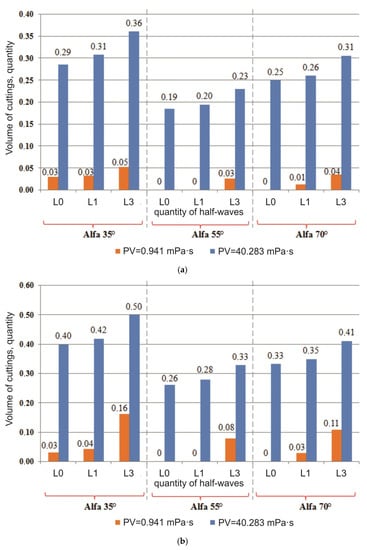
Figure 6.
Comparison of the quality of cleaning from mud with Newtonian and pseudo-plastic liquids with a constant flow of mud, at different zenith angles, the presence of buckling and the speed n = 1.67 s−1 (a) and n = 2.50 s−1 (b).
4. Discussion
An increase in the number of cuttings on the screens confirmed the improvement in cleaning; in addition, it was clear that the pipe, which is in a state of controlled buckling, has a “double” hydromechanical effect on the cuttings plug and on particles settled on the bottom wall of the well.
The first impact of the string is mechanical—the body of the pipe in the area of maximum deflection had a direct physical impact, “breaking” the mud plug and mud dunes, moving the particles, and involving them in a suspended state.
The second effect of the mud is hydrodynamic—the pipe body, which has lost its longitudinal stability, changes its spatial shape, and, consequently, changes the profile of the mud flow moving along the upper wall of the well along the path of least resistance. This causes the mud to “wash out” the accumulated mud and entrain the particles into the general flow. As a result, local flow turbulence is created without the use of special devices, such as turbulators, circulation subs, etc.
The implementation of a hydromechanical method for the destruction of mud plugs in deviated and extended reach wells in order to improve cleaning and avoid problems associated with mud build-up is carried out by controlling and regulating the artificially created pipe buckling. At the moment, there are no field or experimental drill pipes in the world that, in addition to their main functions, can play the role of a device that measures deformations.
As a conceptual solution, the authors propose to develop and include in the DS special sections of pipes in which strain gauges based on a fiber Bragg grating (FBG) are mounted. Due to their advantages, FBG sensors are increasingly being used in control systems in the aviation and space industries [35,36], and they can also be used to measure deformation, displacement, temperature, pressure, tilt angle, as well as acceleration and vibration [37,38,39,40].
FBG fiber optic sensors must be braided from a material that is resistant to the aggressive environment of drilling and cement slurries. The sensors must be rigidly fixed on the inner wall of the drill pipes (Figure 7a) or in the outer wall, in a specially prepared channel (Figure 7b), reinforced with welded material to prevent the weakening of the DS as a result of possible stress concentration. In pipe couplings, the fiber-optic cable is connected to the FBG sensors by means of a quick-disconnect connection and forms a “garland” of sensors—a quasi-distributed differential measuring system that monitors deformations along the pipe body.
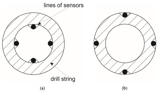
Figure 7.
Conceptual diagram of the location of FBG strain sensors in the body pipes on the inner wall (a) and in the outer wall (b).
The reliability of such a differential measurement system will depend on the mounting methods, materials used and operating conditions. Before including the sensors in the measuring system, it is necessary to calibrate them according to the deformation of the strain gauge and determine the proportionality coefficient between the deformation of the pipe measured by the FBG and the strain gauge.
Thanks to the use of special sections of drill pipe with FBG strain sensors, the operator can control the place of buckling and the spatial shape of the drill bit by adjusting the axial load on the bit, within the established strength limits of the drilling tool. By creating an additional axial load on the bit, the operator forms the buckling of the pipe sections, and the control panel screen displays the spatial shape of the string in the well, taking into account the geometry of the wellbore and drilling parameters.
As a result of controlled buckling, using only mud hydraulics and DS mechanics, without the use of special devices that have a positive effect on well cleaning, hydromechanical destruction of mud plugs and improved removal of broken particles are achieved, and complications associated with the formation of mud pads are prevented.
5. Conclusions
The experimental stand, developed at the St. Petersburg Mining University, is an innovative solution in the field of improving the quality of cleaning directional wells. This study is fundamental, since for the first time the issue of the positive aspect of the loss of stability of the DS was considered, and the positive effect of pipe buckling on the efficiency of cuttings removal was established, taking into account the drilling parameters, technological and rheological properties of the drilling rig, and the angle of inclination of the well.
The analysis of well cleaning quality data, depending on the zenith angle α, confirms the presence of a critical angle α = 55° in the zone with a range of 45–60°, in which the maximum difficulty is noted in the transport of cuttings particles to the day surface—a decrease in the removal of particles to 40–60%.
When conducting a series of experiments No. 1 with a Newtonian liquid, an increase in the efficiency of mud removal by up to eight times was found, at the maximum flow rate of the BR, the rotation frequency n = 0.83 ÷ 2.50 s−1 and the presence of three half-waves string, in comparison with straight DS and strings with the first half-wave. When conducting a series of experiments No. 2 and using a pseudo-plastic liquid as mud, all other things being equal, an increase in the removal of mud cuttings up to 36% was found.
It has been experimentally established that, when the string rotates at a speed of n = 0.83 ÷ 2.50 s−1, at a flow rate Q = 1.25 × 10⁻³ m3/s of a pseudo-plastic liquid with rheological properties, the removal of mud cuttings to the surface increases dozens of times in comparison with the Newtonian fluid.
The authors put forward a hypothesis that the controlled buckling of the string, namely, the number and length of half-waves in the place specified by the operator, allows the breakdown of mud plugs and improves well cleaning, as well as solving the problem of “mud-pads” and the complications and emergencies associated with this phenomenon.
The presented technical and technological solution for the implementation of a hydromechanical method for the destruction of stagnant mud zones is a novel concept and requires further study with the subsequent development of experimental drill pipes based on FBG strain sensors.
The obtained results confirm the need for further study of the effect of pipe buckling on the destruction of mud plugs and cleaning of deviated wells from cuttings, taking into account the multifactorial nature of the drilling process.
Author Contributions
Conceptualization, V.G.K. and M.V.D.; methodology, V.G.K. and M.V.D.; software, V.G.K.; validation, V.G.K. and M.V.D.; formal analysis, V.G.K. and M.V.D.; investigation, V.G.K. and M.V.D.; resources, M.V.D.; data curation, M.V.D.; writing—original draft preparation, V.G.K.; writing—review and editing, M.V.D.; visualization, V.G.K.; supervision, M.V.D.; project administration, M.V.D.; funding acquisition, V.G.K. All authors have read and agreed to the published version of the manuscript.
Funding
This research received no external funding.
Institutional Review Board Statement
Not applicable.
Informed Consent Statement
Not applicable.
Data Availability Statement
All the data used in this study are available in the article.
Acknowledgments
The authors are grateful to Sergey L. Yurtaev, Chief Specialist of Well Construction Laboratory, for his help in designing experimental equipment and support during the research.
Conflicts of Interest
The authors declare no conflict of interest.
References
- Archegov, V.B.; Nefedov, Y.V. The strategy of oil and gas exploration in the energy potential estimation of Russian Arctic shelf seas. J. Min. Inst. 2015, 212, 6–13. (In Russian) [Google Scholar]
- Vasiltsov, V.S.; Vasiltsova, V.M. Strategic planning of Arctic shelf development with apparatus of fractal theory. J. Min. Inst. 2018, 234, 663–672. (In Russian) [Google Scholar] [CrossRef]
- Gao, D.; Tan, C.; Tang, H. Limit analysis of extended reach drilling in South China Sea. Pet. Sci. 2009, 6, 166–171. [Google Scholar] [CrossRef] [Green Version]
- Menand, S.; Isambourg, P.; Sellami, H.; Simon, C.; Bouguecha, A. Axial force transfer of buckled drill pipe in deviated wells. In Proceedings of the SPE/IADC Drilling Conference and Exhibition, Amsterdam, The Netherlands, 17–19 March 2009; pp. 1–12. [Google Scholar] [CrossRef] [Green Version]
- Aldred, W.; Cook, J.; Bern, P.; Carpenter, B.; Hutchinson, M.; Lovell, J.; Rezmer-Cooper, I.; Leder, P.C. Using downhole annular pressure measurements to improving drilling performance. Oilfield Rev. 1998, 10, 40–55. [Google Scholar]
- Dolgopolskiy, A.L. Use of invert-emulsion drilling mud during well construction at Kharyaginsk field. Eng. Pract. 2015, 3, 92. (In Russian) [Google Scholar]
- Zhu, X.; Yi, J.; Liu, Q. Distribution features of cuttings bed and sensitivity analysis of major drilling parameters for cuttings transport in gas drilling horizontal wells. J. Hydrodyn. 2015, 27, 884–893. [Google Scholar] [CrossRef]
- Kiełbasiński, K.; Dobak, P.; Kaczmarek, Ł.; Kowalczyk, S. The influences of local glacitectonic disturbance on overconsolidated clays for upland slope stability conditions: A case study. Appl. Sci. 2021, 11, 10718. [Google Scholar] [CrossRef]
- Blinov, P.A. Determining the stability of the borehole walls at drilling intervals of loosely coupled rocks considering zenith angle. J. Min. Inst. 2019, 236, 172–179. [Google Scholar] [CrossRef] [Green Version]
- Dvoynikov, M.V.; Budovskaya, M.E. Development of a hydrocarbon completion system for wells with low bottomhole temperatures for conditions of oil and gas fields in Eastern Siberia. J. Min. Inst. 2022, 253, 12–22. [Google Scholar] [CrossRef]
- Sandoiu, G.-F. Removing cuttings from deviated and horizontal wells. J. Min. Inst. 2008, 174, 41–42. [Google Scholar]
- Leusheva, E.; Morenov, V.; Liu, T. Dependence of the equivalent circulation density of formate drilling fluids on the molecular mass of the polymer reagent. Energies. 2021, 14, 7639. [Google Scholar] [CrossRef]
- Dobik, Y.A. Effect of drill string rotation on cutting transport in horizontal well. Constr. Oil Gas Wells Land Sea 2019, 3, 25–29. (In Russian) [Google Scholar] [CrossRef]
- Mitchell, R.F. Lateral buckling of pipe with connectors in curved wellbores. In Proceedings of the SPE Drilling Conference, Amsterdam, The Netherlands, 27 February–1 March 2003; pp. 22–32. [Google Scholar] [CrossRef]
- Balaba, V.I.; Zinchenko, O.D. Technical devices for efficiency upgrading of cuttings hydrotransport during directional and horizontal drilling. Equip. Technol. Oil Gas Complex 2015, 3, 23–27. (In Russian) [Google Scholar]
- Oganov, A.S.; Rayhert, R.S.; Tsukarenko, M.S. Problems of cleaning directional and horizontal wells. Neftegaz. Ru 2015, 6, 32–39. (In Russian) [Google Scholar]
- Rayhert, R.S.; Tsukarenko, M.S.; Oganov, A.S. Technological solutions of directional and horizontal well’s cleaning from cuttings. Oil Gas Novations 2016, 3, 28–35. (In Russian) [Google Scholar]
- Nutskova, M.V.; Sidorov, D.A.; Tsikplornu, D.E.; Sergeev, G.M.; Vasilev, N.I. Investigations of oil based muds primary opening of productive formations. Perm. J. Pet. Min. Eng. 2019, 19, 138–149. (In Russian) [Google Scholar] [CrossRef]
- Ulyasheva, N.M.; Leusheva, E.L.; Galishin, R.N. Development of drilling fluid composition with rheological parameters for directional well. J. Min. Inst. 2020, 244, 454–461. (In Russian) [Google Scholar] [CrossRef]
- Sharafutdinov, Z.Z.; Sharafutdinova, R.Z. Water based drilling fluids and management its rheological parameters. Neftegazov. Delo 2004, 1, 1–21. (In Russian) [Google Scholar]
- Jeong, J.; Lim, C.; Park, B.-C.; Bae, J.; Shin, S.-C. Multi-objective optimization of drilling trajectory considering buckling risk. Appl. Sci. 2022, 12, 1829. [Google Scholar] [CrossRef]
- Basovich, V.S.; Buyanovskiy, I.N.; Sapunzhi, V.V. Perspectives of application of light alloy drilling pipes with external helical finning for drilling horizontal wells and branch holes. Drill. Oil 2014, 5, 42–46. (In Russian) [Google Scholar]
- Liu, X.; Vlajic, N.; Long, X.; Meng, G.; Balachandran, B. Nonlinear motions of a flexible rotor with a drill bit: Stick-slip and delay effects. Nonlinear Dyn. 2013, 72, 61–77. [Google Scholar] [CrossRef]
- Piroozian, A.; Ismail, I.; Yaacob, Z.; Babakhani, P.; Ismail, A.S.I. Impact of drilling fluid viscosity, velocity and hole inclination on cuttings transport in horizontal and highly deviated wells. J. Pet. Explor. Prod. Technol. 2012, 2, 149–156. [Google Scholar] [CrossRef]
- Amanna, B.; Movaghar, M.R.K. Cuttings transport behavior in directional drilling using computational fluid dynamics (CFD). J. Nat. Gas Sci. Eng. 2016, 34, 670–679. [Google Scholar] [CrossRef]
- Katende, A.; Segar, B.; Ismai, I.; Sagala, F.; Saadiah, H.H.A.R.; Samsuri, A. The effect of drill-pipe rotation on improving hole cleaning using polypropylene beads in water-based mud at different hole angle. J. Pet. Explor. Prod. Technol. 2019, 10, 1253–1262. [Google Scholar] [CrossRef] [Green Version]
- Hakim, H.; Katende, A.; Sagala, F.; Ismail, I.; Nsamba, H. Performance of polyethylene and polypropylene beads towards drill cuttings transportation in horizontal wellbore. J. Pet. Sci. Eng. 2018, 165, 962–969. [Google Scholar] [CrossRef]
- Heshamudin, N.S.; Katende, A.; Rashid, H.A.; Ismail, I.; Sagala, F.; Samsuri, A. Experimental investigation of the effect of drill pipe rotation on improving hole cleaning using water-based mud enriched with polypropylene beads in vertical and horizontal wellbores. J. Pet. Sci. Eng. 2019, 179, 1173–1185. [Google Scholar] [CrossRef]
- Ytrehus, J.D.; Lund, B.; Taghipour, A.; Carazza, L.; Gyland, K.R.; Saasen, A. Oil-based drilling fluid’s cuttings bed removal properties for deviated wellbores. ASME J. Energy Resour. Technol. 2021, 143, 103003. [Google Scholar] [CrossRef]
- Ytrehus, J.D.; Lund, B.; Taghipour, A.; Kosberg, B.R.; Carazza, L.; Gyland, K.R.; Saasen, A. Hydraulic behavior in cased and open-hole sections in highly deviated wellbores. ASME J. Energy Resour. Technol. 2021, 143, 033008. [Google Scholar] [CrossRef]
- Gao, D.; Huang, W. A review of down-hole tubular string buckling in well engineering. Pet. Sci. 2015, 12, 443–457. [Google Scholar] [CrossRef] [Green Version]
- Gulyayev, V.; Shlyun, N. Influence of friction on buckling of a drill string in the circular channel of a bore hole. Pet. Sci. 2016, 13, 698–711. [Google Scholar] [CrossRef] [Green Version]
- Pei, H.-F.; Yin, J.-H.; Zhu, H.-H.; Hong, C.-Y.; Jin, W.; Xu, D.-S. Monitoring of lateral displacements of a slope using a series of special fibre Bragg grating-based in-place inclinometers. Meas. Sci. Technol. 2012, 23, 25007. [Google Scholar] [CrossRef]
- Kadochnikov, V.G.; Dvoynikov, M.V.; Blinov, P.A. Influence of the drill string spatial form on transport of cuttings in directional wells. Bull. Assoc. Drill. Contract. 2020, 2, 12–19. (In Russian) [Google Scholar]
- Mikhailovskiy, K.V.; Bazanov, M.A. Measuring of residual technological deformations in carbon-plastic with injection optical fiber Bragg sensors. Constr. Compos. Mater. 2016, 2, 54–58. (In Russian) [Google Scholar]
- Leduc, D.; Lecieux, Y.; Morvan, P.-A.; Lupi, C. Architecture of optical fiber sensor for the simultaneous measurement of axial and radial strains. Smart Mater. Struct. 2013, 22, 075002. [Google Scholar] [CrossRef] [Green Version]
- Liu, H.-L.; Zhu, Z.-W.; Zheng, Y.; Liu, B.; Xiao, F. Experimental study on an FBG strain sensor. Opt. Fiber Technol. 2018, 40, 144–151. [Google Scholar] [CrossRef]
- Takeda, N.; Tajima, N.; Sakurai, T.; Kishi, T. Recent advances in composite fuselage demonstration program for damage and health monitoring in Japan. Struct. Control Health Monit. 2005, 12, 245–255. [Google Scholar] [CrossRef]
- Ma, T.; Chen, P.; Zhao, J. Overview on vertical and directional drilling technologies for the exploration and exploitation of deep petroleum resources. Geomech. Geophys. Geo-Energy Geo-Resour. 2016, 2, 365–395. [Google Scholar] [CrossRef] [Green Version]
- Makhsidov, V.V.; Yakovlev, N.O.; Ilichev, A.V.; Shienyuk, A.M. Measuring of carbon-plastic deformation with inside-integrated optical fiber Bragg sensors. Mech. Compos. Mater. Constr. 2015, 21, 360–369. (In Russian) [Google Scholar]
Publisher’s Note: MDPI stays neutral with regard to jurisdictional claims in published maps and institutional affiliations. |
© 2022 by the authors. Licensee MDPI, Basel, Switzerland. This article is an open access article distributed under the terms and conditions of the Creative Commons Attribution (CC BY) license (https://creativecommons.org/licenses/by/4.0/).