
Joint Communication–Motion Planning in Networked Robotic Systems


Abstract
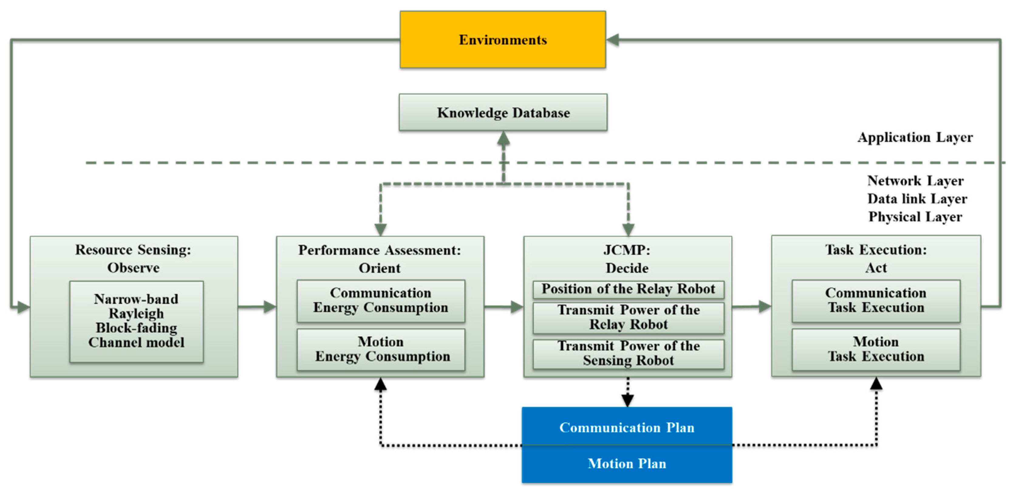
:1. Introduction and Related Works
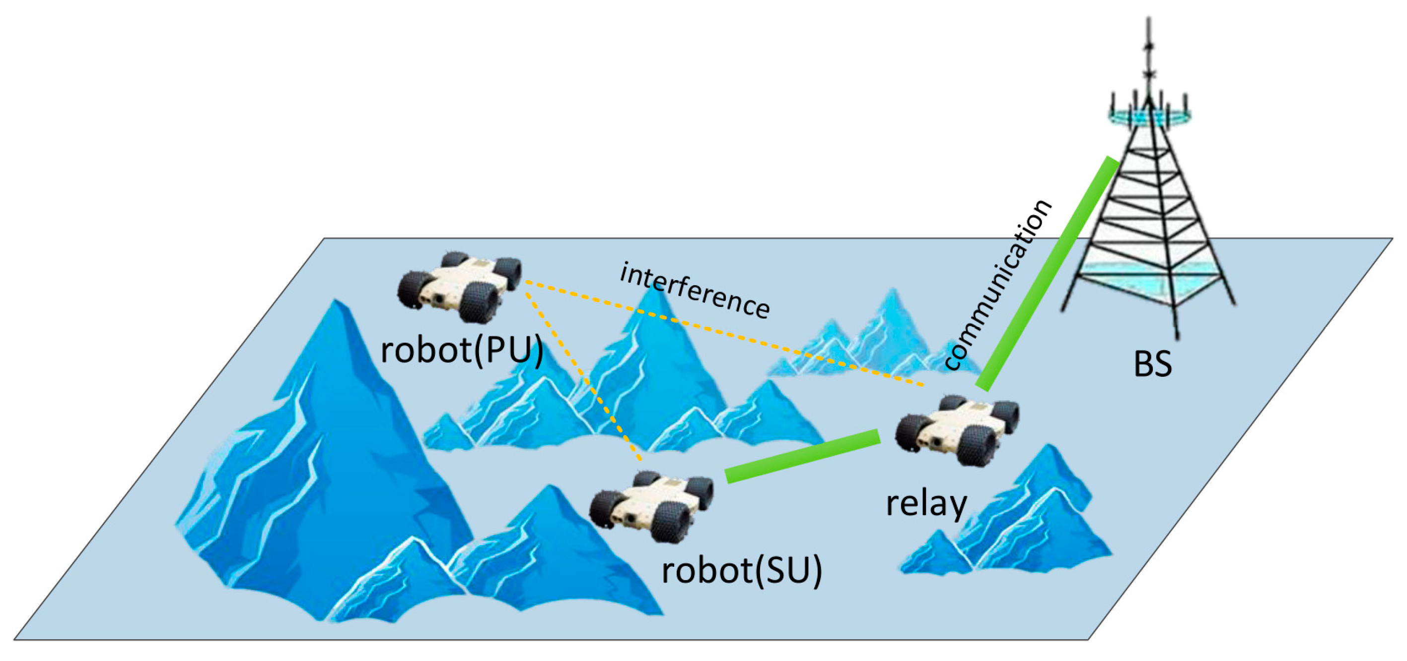
- Based on the OODA loop, we propose a relay-assisted robot surveillance prototype and a cognitive-relay-assisted robot system with interference constraints. We establish the communication system modeling considering the influence of path loss and multi-path fading.
- Under these two systems, we designed JCMP algorithms and jointly optimized the power and motion of the relay robot and the power of the sensing robot.
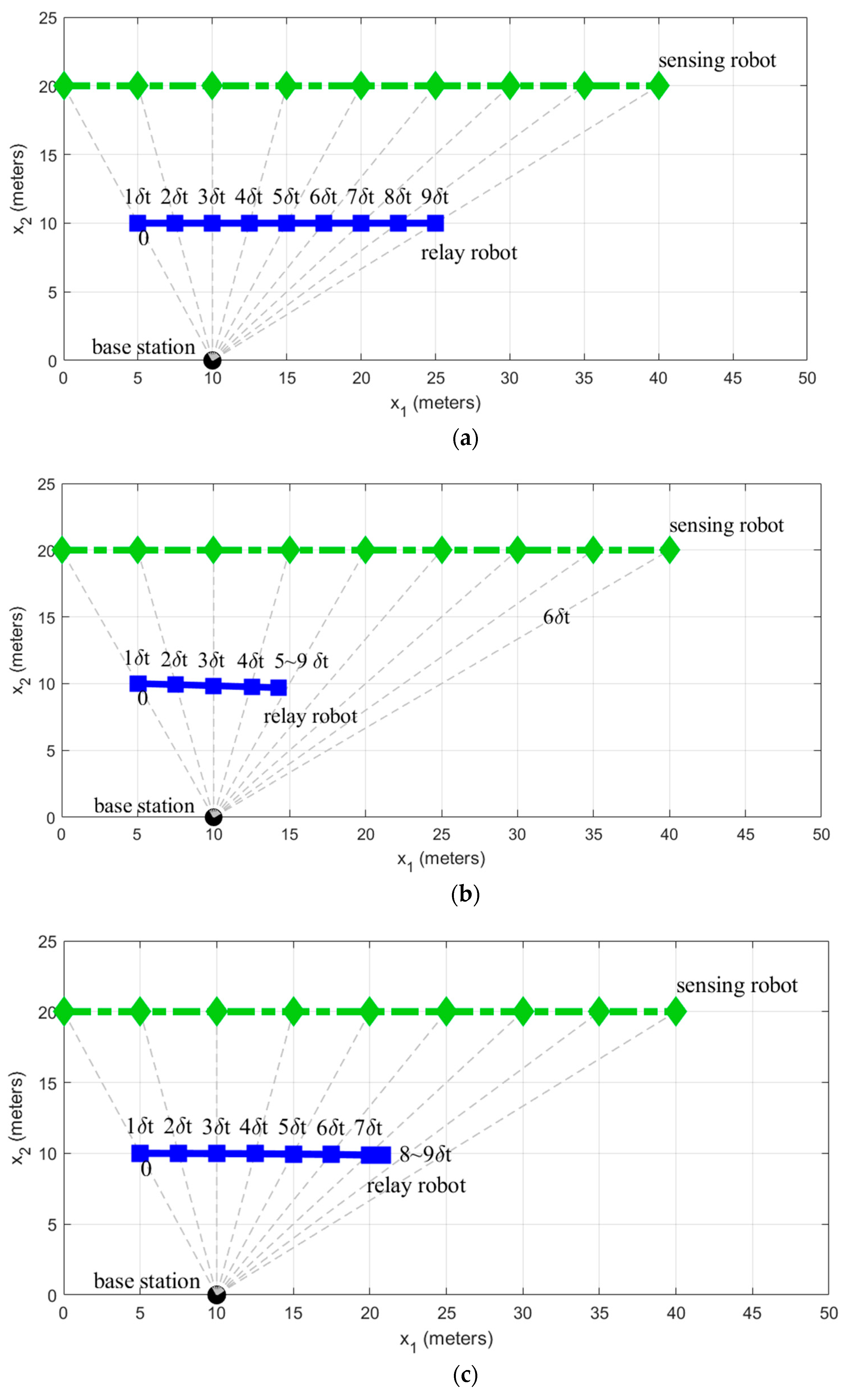
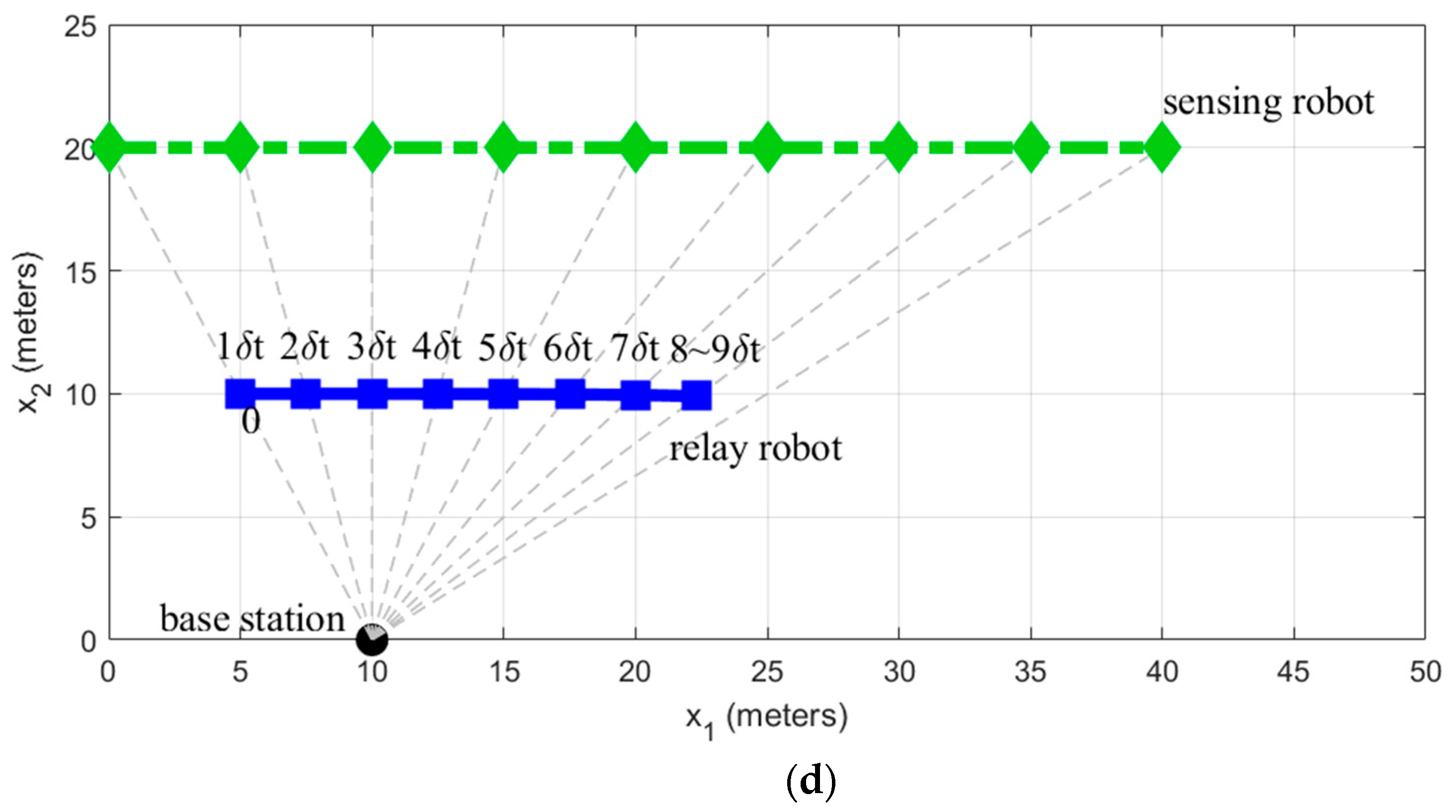
- Numerical results show that the joint planning method using JCMP can save more power than non-JCMP.
2. Conventional Relay-Assisted Robot System
2.1. Resource Sensing: Observe
2.2. Performance Assessment: Orient
2.2.1. Communication Performance Assessment
2.2.2. Motion Performance Assessment
2.3. Joint Communication-Motion Planning: Decide
2.3.1. Problem Formulation
2.3.2. JCMP Solutions
2.4. Task Execution: Act
2.4.1. Implementation
2.4.2. Results
3. Cognitive-Relay-Assisted Robot System with Interference Constraints
3.1. Resource Sensing: Observe
3.2. Performance Assessment: Orient
3.3. Joint Communication-Motion Planning: Decide
3.3.1. Problem Formulation
3.3.2. JCMP Solutions
3.4. Task Execution: Act
3.4.1. Implementation
3.4.2. Results
4. Conclusions and Open Problems
- The system complexity of JCMP is high. This is because JCMP needs to optimize the position and power of multiple robots simultaneously. In practice, it is necessary to reasonably design the hardware architecture of JCMP, so that it can still complete the timely adjustment of various parameters in a flexible external environment.
- Stable communication between robots. This paper is devoted to the development of a networked robot system that completely depends on wireless communication. Since the command and control of robots and the data transmission between robots all depend on wireless communication, a stable communication system is the premise for robots to perform tasks. In the actual environment (especially in the urban environment), multi-path fading, shadow fading, and path loss will affect the stability of wireless communication. Therefore, the wireless channel should be accurately evaluated and modeled before the JCMP is applied in the actual scene.
Author Contributions
Funding
Conflicts of Interest
References
- Kehoe, B.; Patil, S.; Abbeel, P.; Goldberg, K. A Survey of Research on Cloud Robotics and Automation. IEEE Trans. Autom. Sci. Eng. 2015, 12, 398–409. [Google Scholar] [CrossRef]
- Olfati-Saber, R.; Fax, J.A.; Murray, R.M. Consensus and Cooperation in Networked Multi-Agent Systems. Proc. IEEE 2007, 95, 215–233. [Google Scholar] [CrossRef] [Green Version]
- Liu, Z.; Wu, B.; Dai, J.; Lin, H. Distributed communication-aware motion planning for networked mobile robots under formal specifications. IEEE Trans. Control. Netw. Syst. 2020, 7, 1801–1811. [Google Scholar] [CrossRef]
- Muralidharan, A.; Mostofi, Y. Communication-aware robotics: Exploiting motion for communication. Annu. Rev. Control. Robot. Auton. Syst. 2021, 4. [Google Scholar] [CrossRef]
- Licea, D.B.; Bonilla, M.; Ghogho, M.; Lasaulce, S.; Varma, V.S. Communication-aware energy efficient trajectory planning with limited channel knowledge. IEEE Trans. Robot. 2019, 36, 431–442. [Google Scholar] [CrossRef] [Green Version]
- Santra, S.; Paet, L.B.; Laine, M.; Yoshida, K.; Staudinger, E. Experimental Validation of Deterministic Radio Propagation Model developed for Communication-aware Path Planning. In Proceedings of the 2021 IEEE 17th International Conference on Automation Science and Engineering (CASE), Lyon, France, 23–27 August 2021; IEEE: Piscataway, NJ, USA, 2021. [Google Scholar]
- Mardani, A.; Chiaberge, M.; Giaccone, P. Communication-aware UAV path planning. IEEE Access 2019, 7, 52609–52621. [Google Scholar] [CrossRef]
- Luo, R.; Tian, H.; Ni, W. Communication-Aware Path Design for Indoor Robots Exploiting Federated Deep Reinforcement Learning. In Proceedings of the 2021 IEEE 32nd Annual International Symposium on Personal, Indoor and Mobile Radio Communications (PIMRC), Helsinki, Finland, 13–16 September 2021; IEEE: Piscataway, NJ, USA, 2021. [Google Scholar]
- Saboia, M.; Clark, L.; Thangavelu, V.; Edlund, J.A.; Otsu, K.; Correa, G.J.; Varadharajan, V.S.; Santamaria-Navarro, A.; Touma, T.; Bouman, A.; et al. ACHORD: Communication-Aware Multi-Robot Coordination with Intermittent Connectivity. arXiv 2022, arXiv:2206.02245. [Google Scholar]
- Mu, X.; Liu, Y.; Guo, L.; Lin, J.; Schober, R. Intelligent reflecting surface enhanced indoor robot path planning: A radio map-based approach. IEEE Trans. Wirel. Commun. 2021, 20, 4732–4747. [Google Scholar] [CrossRef]
- Yan, Y.; Mostofi, Y. To go or not to go: On energy-aware and communication-aware robotic operation. IEEE Trans. Control. Netw. Syst. 2014, 1, 218–231. [Google Scholar] [CrossRef]
- Gil, S.; Kumar, S.; Katabi, D.; Rus, D. Adaptive communication in multi-robot systems using directionality of signal strength. Int. J. Robot. Res. 2015, 34, 946–968. Available online: http://ijr.sagepub.com/cgi/doi/10.1177/0278364914567793 (accessed on 18 May 2015). [CrossRef]
- Ali, U.; Yan, Y.; Mostofi, Y.; Wardi, Y. An Optimal Control Approach for Communication and Motion Co-optimization in Realistic Fading Environments. In Proceedings of the 2015 American Control Conference (ACC), Chicago, IL, USA, 1–3 July 2015. [Google Scholar]
- Zhang, B.; Wu, Y.; Yi, X.; Yang, X. Joint communication-motion planning in wireless-connected robotic networks: Overview and design guidelines. arXiv 2015, arXiv:1511.02299. [Google Scholar]
- Liu, Q.; Zhou, S.; Giannakis, G. Cross-Layer Combining of Adaptive Modulation and Coding With Truncated ARQ Over Wireless Links. IEEE Trans. Wirel. Commun. 2004, 3, 1746–1755. [Google Scholar] [CrossRef]
- Zhang, B.; Dong, C.; El-Hajjar, M.; Hanzo, L. Outage Analysis and Optimization in Single and Multi-User Wireless Energy Harvesting Networks. IEEE Trans. Veh. Technol. 2015, 65, 1464–1476. [Google Scholar] [CrossRef] [Green Version]
- Mei, Y.; Lu, Y.-H.; Hu, Y.; Lee, C. Deployment of mobile robots with energy and timing constraints. IEEE Trans. Robot. 2006, 22, 507–522. [Google Scholar]
- El-Hajjar, M.; Hanzo, L. Multifunctional MIMO systems: A combined diversity and multiplexing design perspective. IEEE Wirel. Commun. 2010, 17, 73–79. [Google Scholar] [CrossRef] [Green Version]


| Ref. | Network Topology | Design Objective | Exploited DoF |
|---|---|---|---|
| [3] | Multi-hop | Maximizing communication quality of service | Mobility |
| [4] | Point-to-Point | Minimizing the total energy consumption | Mobility |
| [5] | Point-to-Point | Minimizing the total energy consumption | Mobility |
| [6] | Point-to-Point | Maximizing the strength of receiving signal | Mobility |
| [7] | Point-to-Point | Maximizing the throughput guarantees to the video streaming | Mobility |
| [8] | Multi-hop | Maximizing the long-term throughput | Mobility, Trans-mit Power |
| [9] | Multi-Unicast | Maximizing the bandwidth-usage | Topology |
| [10] | Multi-hop | Maximizing the communication rate | Transmit Power, Phase-shift |
| [11] | Point-to-Point | Minimizing the total energy consumption | Mobility |
| [12] | Multi-Unicast | Minimizing the service discrepancy among all pairs of robots | Mobility |
| [13] | Point-to-Point | Minimizing the total energy consumption | Mobility, Trans-mit Power |
Publisher’s Note: MDPI stays neutral with regard to jurisdictional claims in published maps and institutional affiliations. |
© 2022 by the authors. Licensee MDPI, Basel, Switzerland. This article is an open access article distributed under the terms and conditions of the Creative Commons Attribution (CC BY) license (https://creativecommons.org/licenses/by/4.0/).
Share and Cite
Zhang, Z.; Zhang, B.; Wu, Y. Joint Communication–Motion Planning in Networked Robotic Systems. Appl. Sci. 2022, 12, 6261. https://doi.org/10.3390/app12126261
Zhang Z, Zhang B, Wu Y. Joint Communication–Motion Planning in Networked Robotic Systems. Applied Sciences. 2022; 12(12):6261. https://doi.org/10.3390/app12126261
Chicago/Turabian StyleZhang, Zixuan, Bo Zhang, and Yunlong Wu. 2022. "Joint Communication–Motion Planning in Networked Robotic Systems" Applied Sciences 12, no. 12: 6261. https://doi.org/10.3390/app12126261
APA StyleZhang, Z., Zhang, B., & Wu, Y. (2022). Joint Communication–Motion Planning in Networked Robotic Systems. Applied Sciences, 12(12), 6261. https://doi.org/10.3390/app12126261