Article

Performance of Numerically Optimized Tuned Mass Damper with Inerter (TMDI)

1
Maurer Switzerland GmbH, Grossplatzstrasse 24, 8118 Pfaffhausen, Switzerland
2
OTH Regensburg, Galgenbergstrasse 30, 93049 Regensburg, Germany
3
Maurer Engineering GmbH, Frankfurter Ring 193, 80807 Munich, Germany
4
Maurer SE, Frankfurter Ring 193, 80807 Munich, Germany
*
Author to whom correspondence should be addressed.
Appl. Sci. 2022, 12(12), 6204; https://doi.org/10.3390/app12126204
Submission received: 11 April 2022 / Revised: 15 June 2022 / Accepted: 16 June 2022 / Published: 18 June 2022
(This article belongs to the Special Issue Efficient Damping and Isolation Systems for Civil Structures)

Abstract

:
In recent years, the Tuned Mass Damper with inerter (TMDI) has received significant attention. The inerter is defined to exert a force that is in proportion to the relative acceleration of the two inerter terminals. Here, two TMDI topologies are investigated. The conventional topology is given by the inerter being in parallel to the spring and viscous damper of the TMDI. The other topology is the serial arrangement of spring, inerter and viscous damper being in parallel to the stiffness of the mass spring oscillator of the TMDI. While the first topology intends to increase the inertial force of the TMDI, the second topology aims at producing an additional degree of freedom. The considered TMDI concepts are simulated for harmonic and random excitations, with parameters set according to those described in the literature and with numerically optimized parameters which minimize the primary structure displacement response. The classical TMD is used as a benchmark. The findings are twofold. The conventional TMDI with typical inertance ratio of 1% and the very small value of 0.02% performs significantly worse than the classical TMD with the same mass ratio. In contrast, the TMDI with an additional degree of freedom can improve the mitigation of the primary structure if the inertance ratio is set very small and if the TMDI parameters are numerically optimized.

1. Introduction

The Tuned Mass Damper (TMD), first described by Den Hartog [1], is a widely used passive device used to control resonant vibrations when the disturbing frequency is unknown. It is a damped one-degree-of-freedom oscillator that is connected to the primary structure, whereby the resulting system is a highly damped two-degrees-of-freedom system. The two optimization parameters of the TMD are its natural frequency and damping ratio. For the selected mass ratio between the TMD oscillating mass and the target modal mass of the vibrating structure, these parameters can be optimized for minimum modal displacement, velocity and acceleration for harmonic and broad band excitations [2]. TMDs are widely used in footbridges [3,4] and high-rise buildings [5,6] to guarantee the required acceleration limits [7,8,9], in street bridges to provide the required level of damping [10,11], in railway bridges to avoid the loss of contact between wheels and track [12], and in flag masts and wind power stations to reduce bending vibrations [13,14].
To enhance the mitigation efficiency and broadband characteristics of TMDs, several concepts have been developed. Active and semi-active TMDs are based on the real-time control of TMD natural frequency and damping according to the actual frequency of vibration [15,16,17,18,19]. The resulting enhanced vibration suppression can be used to guarantee lower vibration limits or to ensure vibration limits with reduced TMD mass [6]. Another approach to make TMDs more efficient is simply to increase their oscillating mass. However, limited TMD installation space and costs make this approach unfavorable. Given this, the TMD with inerter, abbreviated as TMDI, has received much attention during the past decade. The ideal inerter is defined to exert a force in proportion to the relative acceleration of its two grounds or terminals, respectively. That the development of real inerters with minimum or even zero friction is a challenging task is seen from the works [20,21]. Originally, the inerter was used in vehicle suspension systems to improve ride comfort [22]. The use of inerters in the field of vibration isolation in a more general way is described in [23]. When the inerter is used in combination with the classical TMD, there are many possible TMDI topologies. Some topologies aim at replacing the TMD mass, some intend to increase TMD inertial force and some target producing an additional degree of freedom whereby the primary structure with TMDI behaves as a three-degrees-of-freedom system. A profound overview of possible TMDI topologies together with closed-form solutions of the related parameters can be found in [24,25,26,27]. TMDI efficiency has been investigated for various TMDI configurations for earthquake excitation [28,29,30], wind excitation [31,32,33,34], and harmonic and random excitations of the primary structure [35,36,37]. The studies in [35,36] were made for various TMDI parallel and serial arrangements of inerters, and stiffness and damping elements and optimum TMDI parameters in table format are provided. The authors of [37] show that even very complex inerter configurations are thinkable. Besides the investigations of various TMDI topologies, studies have also been performed to investigate the influence of the inerter ground on the primary structure [38,39]. This literature survey gives a brief overview of the topics related to inerters that are being investigated.
The present work aims at analyzing the mitigation efficiency of the TMDI not with analytical parameters but with numerically optimized parameters to ensure optimality. The optimization criterion is minimum primary structure displacement response. The TMDI is assumed to be located at the anti-node position of the first bending mode of the primary structure (Figure 1a), and the inerter is grounded to the antinode position as well because this is the most realistic scenario for real applications. Two typical TMDI configurations are considered. The conventional topology is given by the parallel arrangement of inerter, spring and viscous damper, aiming at increasing the inertial force of the TMDI mass, as in Figure 1b. The benchmark for this TMDI configuration is the classical TMD with the same mass ratio (Figure 1c). The other considered TMDI topology is the serial arrangement of spring, inerter and viscous damper together with the main spring of the TMDI mass, as proposed in [25] (Figure 1d). This topology aims to produce an additional degree of freedom of the inerter. The performance of the resulting three-degrees-of-freedom system is compared to the performance of the primary structure with two half TMDs, both with half mass ratio and different natural frequencies and damping ratios, leading to a three-degrees-of-freedom system as well (Figure 1e). The comparative study is performed for both harmonic and random excitations. The performances of the simulated TMDs and TMDIs are assessed by the primary structure displacement response and the damper relative motion response.
The structure of the paper is as follows. Section 2 describes the modelling of the considered TMDI concepts and the associated TMD benchmarks. To make the modelling closer to reality, an inerter model based on a fly wheel mechanism is considered as well. Section 3 describes the simulation procedure concerning the optimizations of the considered TMDI and TMD systems and their performance assessments. Section 4 shows the numerical results of the considered TMDI configurations and the benchmark TMD with the same mass ratio. The comparison is made in a systematic way. First, the conventional TMDI with the commonly used inertance ratio of 1% and with parameters according to those described in the literature is compared to the TMD with Den Hartog parameters that minimize the primary structure displacement response, assuming zero structural inherent damping [1]. Then, the conventional TMDI and TMD with numerically optimized parameters are compared and the very small inertance ratio of 0.02% is considered as well. For the serial TMDI, the parameters are numerically optimized for inertance ratios of 1% and 0.02% due to the lack of analytical optimum parameter solutions. For the TMDI with an inertance ratio of 1%, the frequency response function is characterized by two peaks. Therefore, the classical TMD is used here as a benchmark. For the TMDI with an inertance ratio of 0.02%, the frequency response function shows three peaks due to the additional degree of freedom induced by the serial inerter with the low inertance ratio of 0.02%. Consequently, the benchmark is given here by two half TMDs with different natural frequencies and damping ratios. Discussions of these comparative studies are included in Section 4. The article ends with a short summary and conclusions in Section 5.

2. Modelling

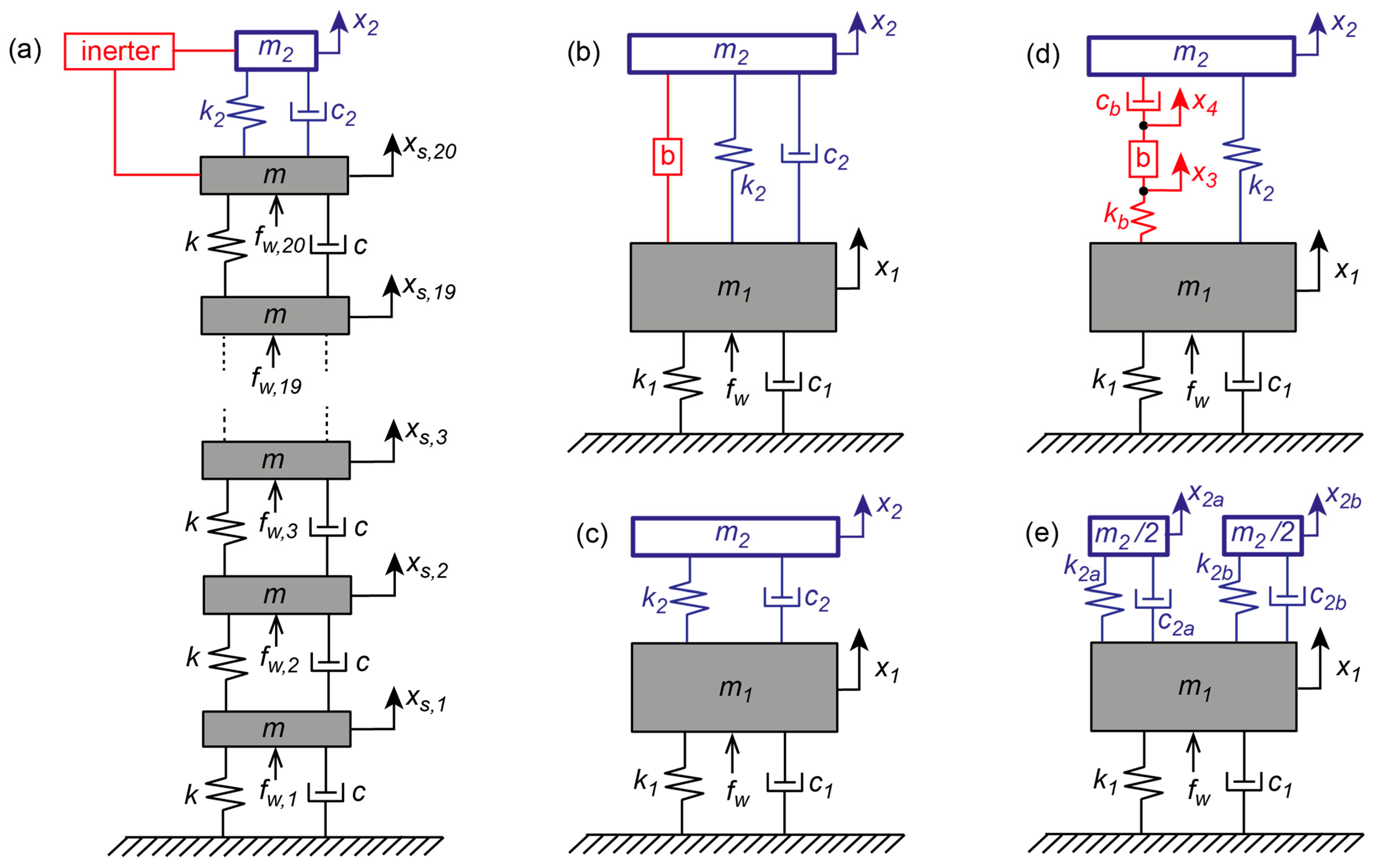
2.1. Primary Structure

The primary structure is modelled by the modal component that needs to be mitigated by the damper. Therefore, the model is given by the following single-degree-of-freedom system [40]
m 1 x ¨ 1 + c 1 x ˙ 1 + k 1 x 1 = f e x  
c 1 = 2   ζ 1   m 1 ( 2   π   f 1 )  
k 1 = m 1 ( 2   π   f 1 ) 2  
where m 1 denotes the modal mass; c 1 is the viscous damping coefficient, which is given by the damping ratio ζ 1 ; k 1 is the stiffness coefficient, which results from the eigenfrequency f 1 ; x ¨ 1 ,   x ˙ 1 ,   x 1 describe the modal acceleration, velocity and displacement; and f e x is the excitation force. The chosen primary structure modal parameters represent typical values of a tall building that may be susceptible to wind excitation and therefore may require a mass damper (Table 1). Notice that the choice of the structural modal parameters does not influence the outcome of the comparative study under consideration. However, the selection of the modal parameters influences the optimum mass damper parameters that are given for all considered mass damper topologies.

2.2. Primary Structure with TMD

The model of the primary structure with TMD is given by the following two-degrees-of-freedom system (Figure 1c):
[ m 1 0 0 m 2 ] [ x ¨ 1 x ¨ 2 ] + [ c 1 + c 2 c 2 c 2 c 2 ] [ x ˙ 1 x ˙ 2 ] + [ k 1 + k 2 k 2 k 2 k 2 ] [ x 1 x 2 ] = [ f e x 0 ]  
where m 2 denotes the TMD mass, c 2 is the TMD viscous damping coefficient, k 2 is the TMD stiffness coefficient, x ˙ 1 x ˙ 2 describes the TMD relative velocity, x 1 x 2 is the TMD relative motion, and the modeshape factor of the first bending mode at TMD position is not included, as it is 1 (see Figure 1a). The parameters of the considered TMDs that are designed according to Den Hartog’s rules and numerically optimized for minimum structural displacement are given in Table 2. The optimization criterion for minimum structural displacement was chosen to ensure a fair comparison with the performance of the TMDI with analytical parameters according to [33], which are intended to yield at least a structural displacement response close to its minimum.

2.3. Primary Structure with TMDI with Inerter in Parallel to the Spring and Viscous Damper

The topology of the conventional TMDI is given by the parallel arrangement of the inerter, spring and viscous damper, as depicted in Figure 1b. The idea behind this topology is that the inerter, although producing a force in proportion to the relative acceleration of its two terminals, increases the TMD inertial force without adding real mass. The model of the primary structure with conventional TMDI is given by the following two-degrees-of-freedom system:
[ m 1 + b b b m 2 + b ] [ x ¨ 1 x ¨ 2 ] + [ c 1 + c 2 c 2 c 2 c 2 ] [ x ˙ 1 x ˙ 2 ] + [ k 1 + k 2 k 2 k 2 k 2 ] [ x 1 x 2 ] = [ f e x 0 ]  
where b denotes the so-called inertance with unit (kg) that is determined by the selected inertance ratio β as follows:
b = β   m 1
Notice that the inertance b not only increases the mass m 2 of the TMDI but b occurs at all locations in the modal mass matrix of Equation (5) because the inerter force f b is in proportion to the relative acceleration of the inerter grounds, which is here the difference between primary structure modal acceleration x ¨ 1 and acceleration x ¨ 2 of the TMDI mass m 2 .
f b = b   ( x ¨ 1 x ¨ 2 )
For the TMDI with conventional topology and the often-adopted inertance ratio β = 1%, the parameters f 2 , ζ 2 , k 2 and c 2 are, on the one hand, designed according to the closed-form solutions (8)–(11), according to [33], and, on the other hand, the parameters k 2 and c 2 are numerically optimized for minimum structural displacement (Table 3).
f 2 = f 1 1 + 0.5 ( β + μ ) 1 + β + μ
  k 2 = ( b + m 2 )   ( 2 π f 2 ) 2
ζ 2 = ( β + μ ) ( 1 + 0.75 ( β + μ ) ) 4 ( 1 + β + μ ) ( 1 + 0.5 ( β + μ ) )
  c 2 = 2   ζ 2   ( b + m 2 )   ( 2 π f 2 )
According to [33], the closed-form solutions (8)–(11) do not minimize the structural displacement response but yield a reasonable suboptimal solution as these solutions are derived for a classical TMD with a total mass ratio μ + β . This means that one can expect a good but not optimal performance of the conventional TMDI with parameters (8)–(11). For the inertance ratio β = 0.02%, only the numerically optimized TMDI is used for the comparative study because the very small inertance ratio of 0.02% has not been considered in the literature so far.

2.4. Primary Structure with TMDI with Inerter in Series with Stiffness and Viscous Damper

Another topology is described in [25], where the spring k 2 is in parallel with the serial arrangement of the spring with stiffness k b , the inerter with inertance b and the viscous damper with viscous coefficient c b , as depicted in Figure 1d. The idea behind this topology is to produce an additional degree of freedom by setting the inerter between the spring and viscous damper. The relevant equations of motion are given as follows:
[ m 1 0 0 m 2   0 0 0 0 0 0 0 0   b b 0 0 ] [ x ¨ 1 x ¨ 2 x ¨ 3 x ¨ 4 ] + [ c 1   0 0   0   0   0 0   0   0   0   0   c b     0   0   0 c b ] [ x ˙ 1 x ˙ 2 x ˙ 3 x ˙ 4 ] + [ ( k 1 + k 2 + k b ) k 2 k 2 k b k 2   k b 0 k b 0   k b   0 k b   0     k b 0   k b 0 ] [ x 1 x 2 x 3 x 4 ] = [ f e x 0 0 0 ]
As for the first conventional TMDI layout, this TMDI topology was computed for the usually adopted inertance ratio β = 1% and for the very small value of 0.02% as well. For both inertance ratios, the parameters of the TMDI were numerically optimized for minimum structural displacement to ensure the optimality of this mass damper type (Table 4).

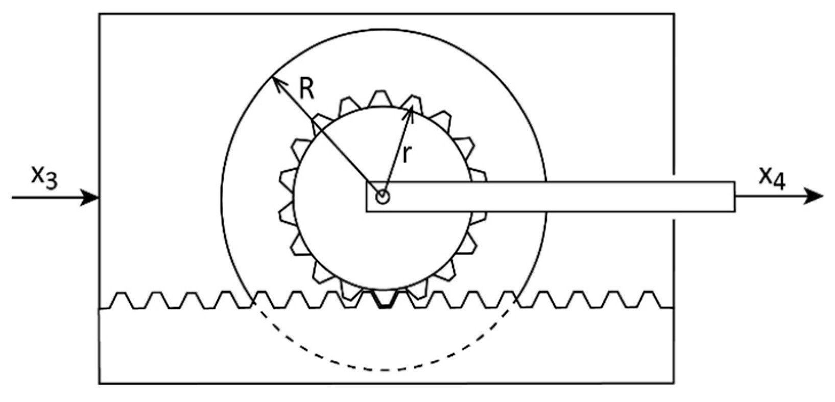
2.5. Primary Structure with TMDI with Fly Wheel Inerter in Series with Stiffness and Viscous Damper

For the TMDI with a serial arrangement of spring, inerter and viscous damper, an inerter model based on the fly wheel principle s computed. The fly wheel that rotates accelerated when the relative motion ( x 3 x 4 ) between the housing and the steel rod of the fly wheel was accelerated (Figure 2). The mass of the housing including the gear rod is denoted as m 3 and the mass of the fly wheel including the steel rod and the axle is m 4 (Table 5).
The moment of inertia I of the fly wheel with mass m w h e e l and radius R is equal to the moment of inertia resulting from the envisaged inertance b and the gear radius r .
I = m w h e e l   R 2 2 = b   r 2
r can be derived to obtain the envisaged inertance, which yields r = 0.288 m for m w h e e l = 3388 kg and R w h e e l = 0.7 m (Table 5). For this TMDI type, the equations of motion, which avoid the zeros in the fourth line of the mass matrix in (12), are as follows:
[   m 1 0 0 m 2 0 0 0 0   0   0 0   0 b + m 3 b b b + m 4 ]   [ x ¨ 1 x ¨ 2 x ¨ 3 x ¨ 4 ] + [ c 1   0 0   c b   0   0 0   c b   0   0   0   c b     0   0   0   c b ] [ x ˙ 1 x ˙ 2 x ˙ 3 x ˙ 4 ] + [ ( k 1 + k 2 + k b ) k 2 k 2 k 2   k b 0 0 0   k b   0 0   0     k b   0   0   0 ] [ x 1 x 2 x 3 x 4 ] = [ f e x 0 0 0 ]
The TMDI model (14) is computed for the inertance ratio β = 0.02%, which turns out to be much more favourable than β = 1%, with numerically optimized parameters k 2 , k b and c b (Table 4).

2.6. Primary Structure with Two Half TMDs

The TMDI topology with the serial arrangement produces an additional degree of freedom, i.e., the primary structure with this TMDI behaves as a three-degrees-of-freedom system. Therefore, the appropriate benchmark is the primary structure with two different TMDs, resulting in a three-degrees-of-freedom system as well. The mass ratio of each TMD is selected to be 0.5%, whereby the mass ratio of both TMDs together is equal to 1%. The equations of motion of the primary structure with two different TMDs but with the same mass are as follows (Figure 1e):
[ m 1 0 0 0 m 2 / 2 0 0 0 m 2 / 2 ] [ x ¨ 1 x ¨ 2 x ¨ 3 ] + [ c 1 + c 2 a + c 2 b c 2 a c 2 b c 2 a c 2 a 0 c 2 b 0 c 2 b ] [ x ˙ 1 x ˙ 2 x ˙ 3 ] + [ k 1 + k 2 a + k 2 b k 2 a k 2 b k 2 a k 2 a 0 k 2 b 0 k 2 b ] [ x 1 x 2 x 3 ] = [ f e x 0 0 ]
The parameters k 2 a , c 2 a , k 2 b and c 2 b are numerically optimized for minimum primary structure displacement (Table 2). Notice that the numerically optimized stiffness and viscous damping coefficients are not equal because one half of the TMD is tuned to mitigate the left peak of the primary structure with classical TMD and the other half of the TMD is tuned to the right peak.

3. Simulation Procedure

3.1. TMDI Optimization

The Matlab (1994–2022 The MathWorks, Inc.) functions “fminsearch” and “optimset” were used for the optimization of the parameters of the considered TMDI concepts. The optimization criterion is the minimization of the steady-state displacement response of the primary structure under harmonic excitation (16). The fact that optimum parameters were obtained will be demonstrated by the equal peaks of the two-peak curve of the structure with parallel TMDI and of the three-peak curve of the structure with TMDI with an additional degree of freedom.
o p t i m i z a t i o n   c r i t e r i o n = m i n ( X 1 )

3.2. TMD Optimization

The classical TMD is computed for the same mass ratio as the TMDI to ensure the same masses. The stiffness and viscous damping coefficients of the classical TMD are designed according to two methods. First, the well-known Den Hartog’s rules are adopted, which minimize the structural displacement response if the primary structure damping ratio is negligible [1]. Second, TMD parameters are numerically optimized using the same optimization functions as for the TMDI in order to obtain equal normalized displacement peaks, even for ζ 1 = 1%, and also for the benchmark of the two half TMDs with different natural frequencies and damping ratios.

3.3. Assessments of TMDI and TMD
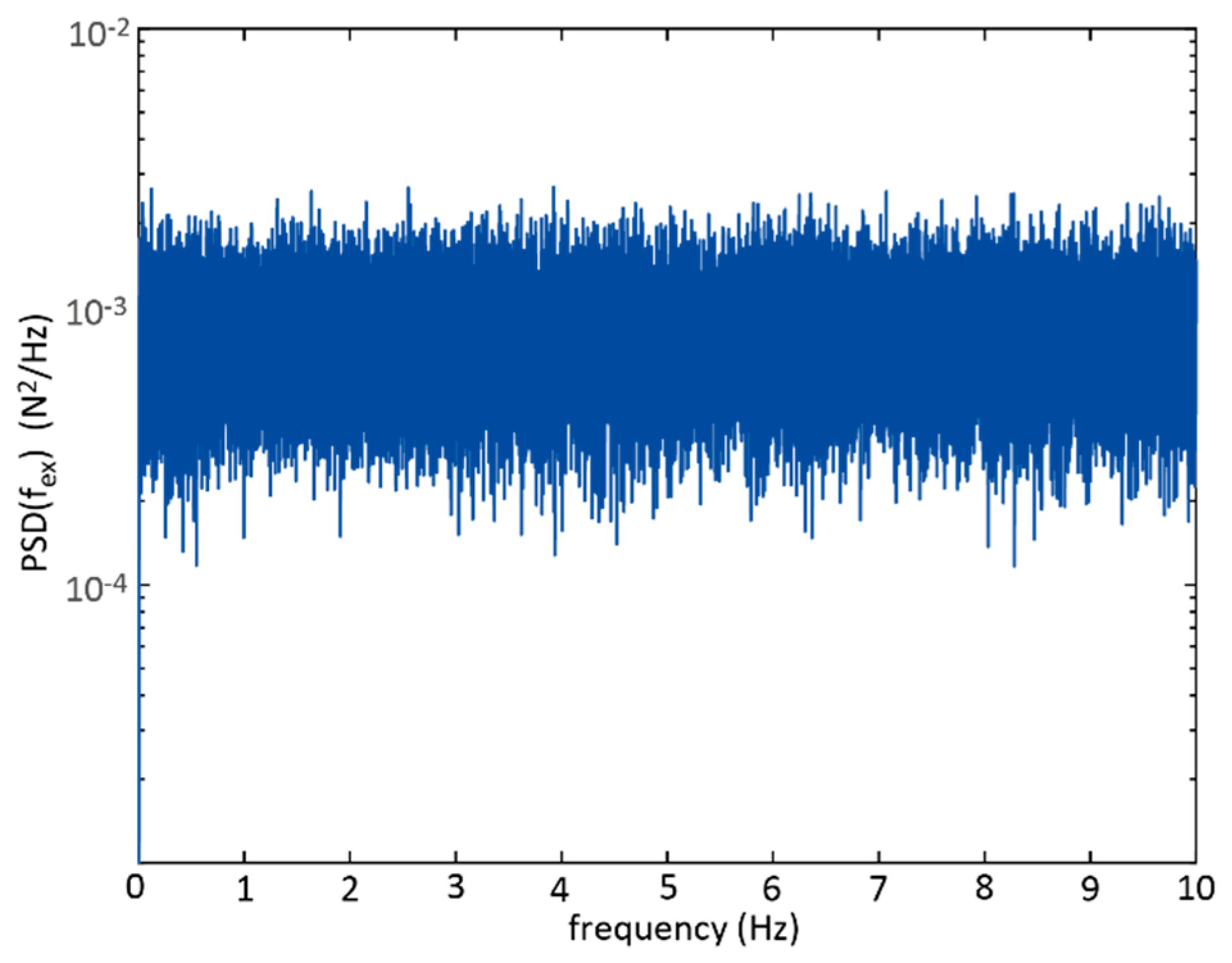
For harmonic excitation, TMDI and TMD are assessed by their steady state primary structure displacement response, which is normalized by the static displacement X 1 , s t a t i c = k 1 / F e x , where F e x denotes the excitation force amplitude (17). The relative motion amplitudes of the TMDI and TMD, respectively, are normalized by the maximum value of the TMD with 1% mass ratio and by adopting Den Hartog parameters (18).
X 1 / X 1 , s t a t i c = X 1   k 1 / F e x
( X 1 X 2 ) / { m a x ( X 1 X 2 ) } T M D
For random excitation, the primary structure displacement response and the damper relative motion response were assessed by their transfer functions T F x 1 and T F x d , respectively, between these displacements and the excitation force ((19) and (20)). The transfer function of the damper relative motion is normalized by the maximum of the transfer function of the damper relative motion of the benchmark TMD with 1% mass ratio.
T F x 1 = P S D ( x 1 ) P S D ( f e x )
T F x d = P S D ( x 1 x 2 ) P S D ( f e x ) / { m a x ( P S D ( x 1 x 2 ) P S D ( f e x ) ) } T M D

3.4. Excitation

Harmonic and random excitations were adopted. For harmonic excitation, steady state responses of the primary structure displacement and damper relative motion were computed for an excitation frequency range between 0.85 ×   f 1 and 1.15 ×   f 1 . For random excitation, a zero-mean white noise signal at sampling frequency 200 Hz was generated that was high pass-filtered (second-order filter) at 0.005 Hz to remove any offset and low pass-filtered (second-order filter) at 99 Hz to remove unnecessary higher frequencies, considering f 1 = 0.14 Hz (Figure 3).

4. Results

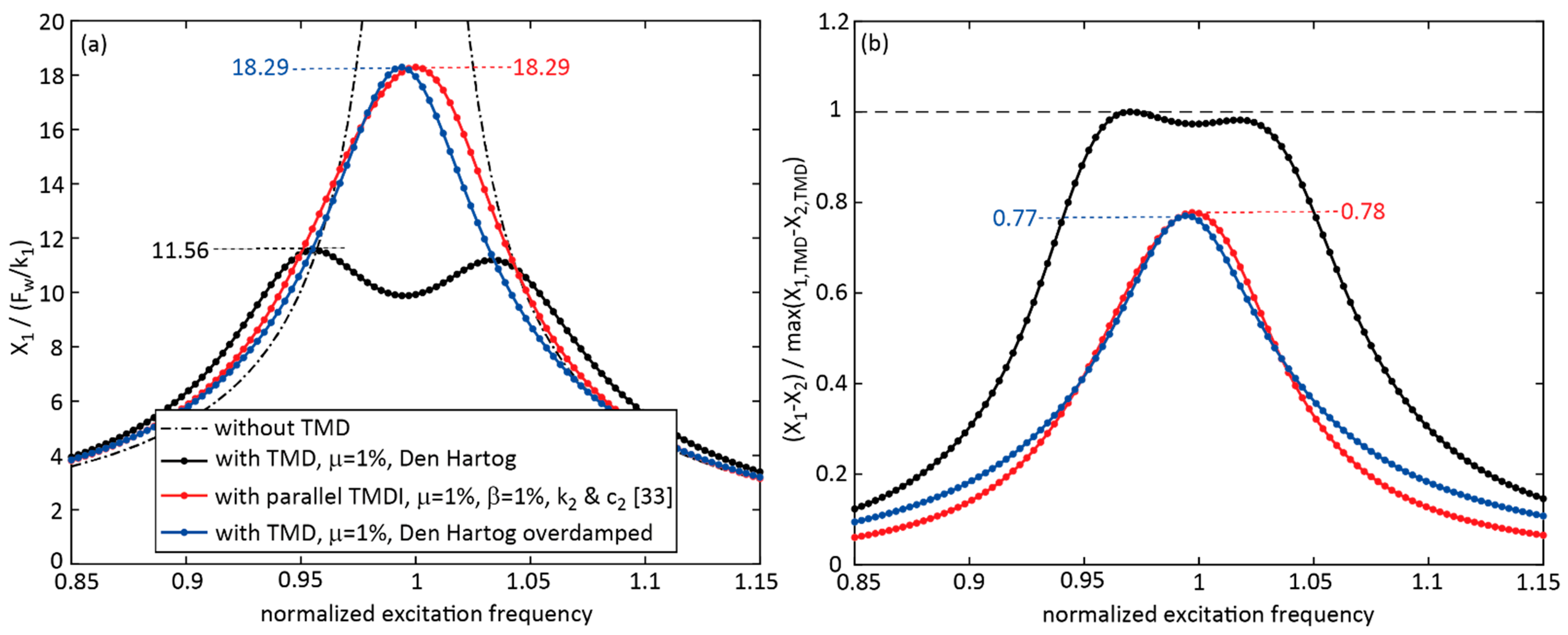
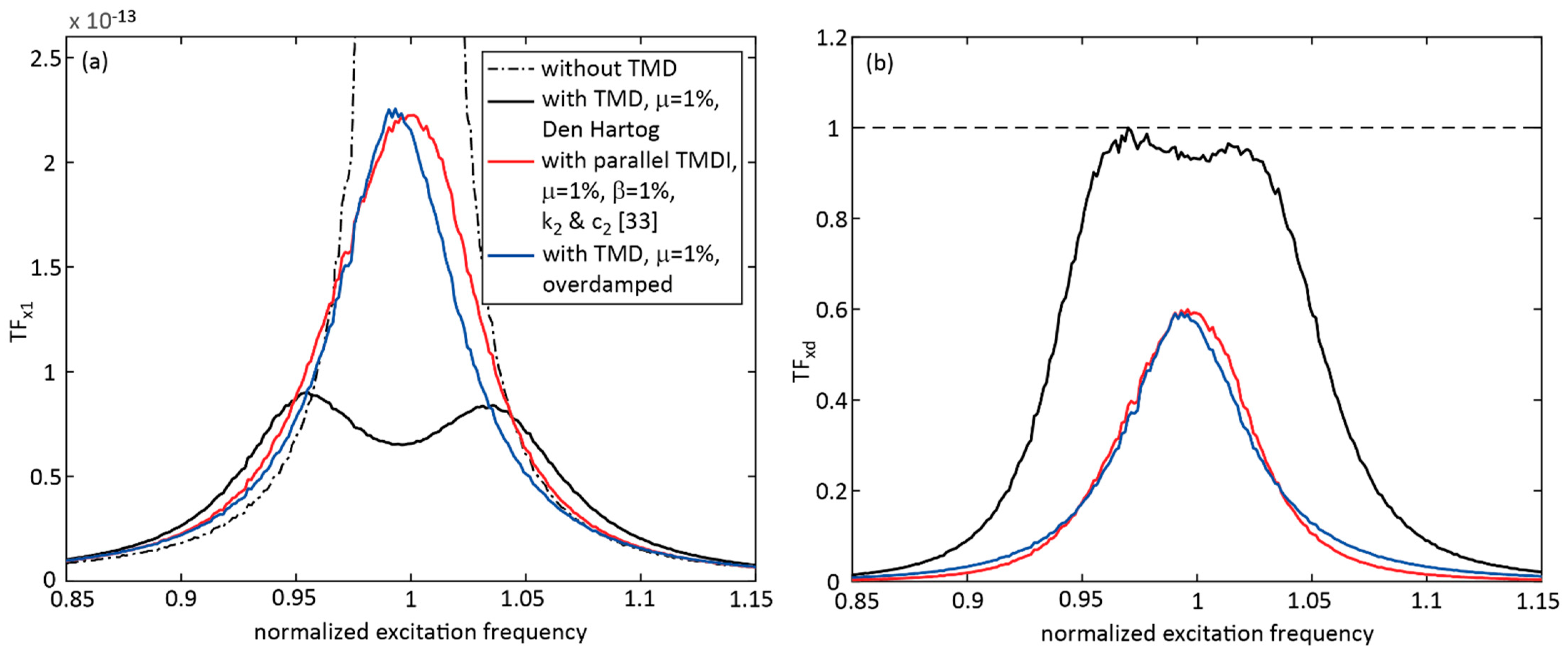
4.1. TMDI with Inerter in Parallel to Stiffness and Viscous Damper, β = 1%, Tuning According to Parameters Described in the Literature

First, the normalized structural displacement and damper relative motion of the TMDI with an inerter in parallel to the stiffness and viscous damper, β = 1% and parameters set according to [33] were compared to the classical TMD with the same mass ratio for harmonic and random excitations; see Figure 4 and Figure 5. The results demonstrate that the TMDI with tuning according to [33] led to a far greater structural displacement than the classical TMD. The shape of the primary structure response due to the TMDI corresponded well with the results presented in [32]. The response of the TMDI was similar to the response due to an overdamped TMD, which was confirmed by the simulation result due to a TMD with the same mass ratio and a viscous damping coefficient that was 2.3434 times greater than the value according to Den Hartog (Table 2). The observation that the design according to [33] leads to an overdamped TMDI was also seen from the viscous damping coefficient of 121.66 kNs/m (Table 3), which is very close to the value of the overdamped TMD 2.3434 × 53.069 kNs/m = 124.36 kNs/m (Table 2). The reason for the extremely suboptimal tuning of the TMDI according to [33] is that the TMDI parameters are derived for a TMD with a mass ratio μ + β that is not correct, since the inerter force is in proportion to the relative acceleration between the primary structure and the damper mass.

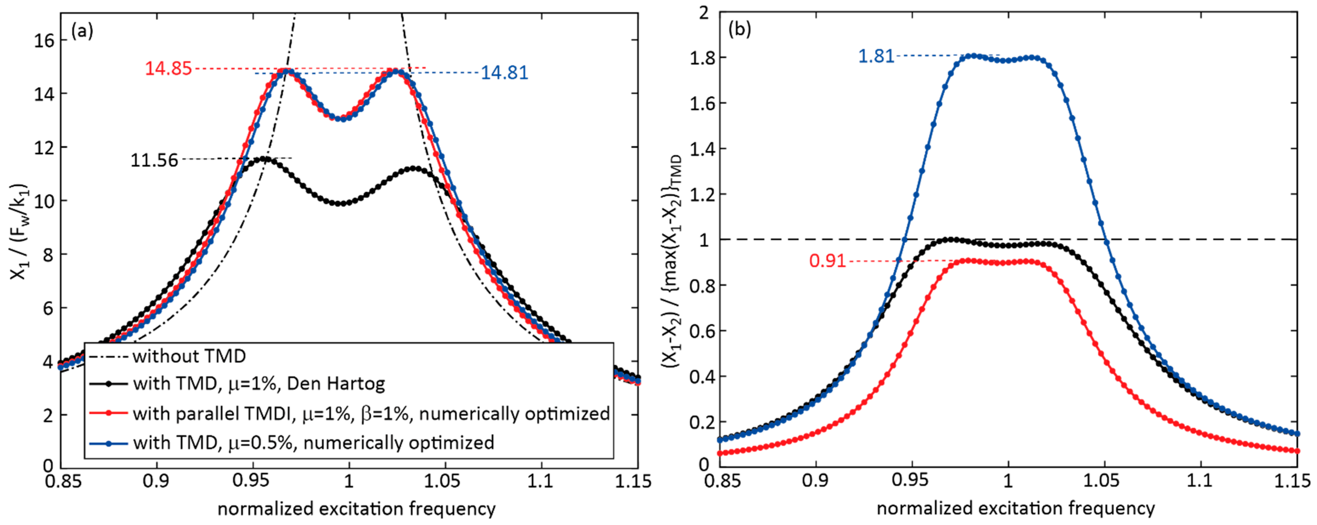
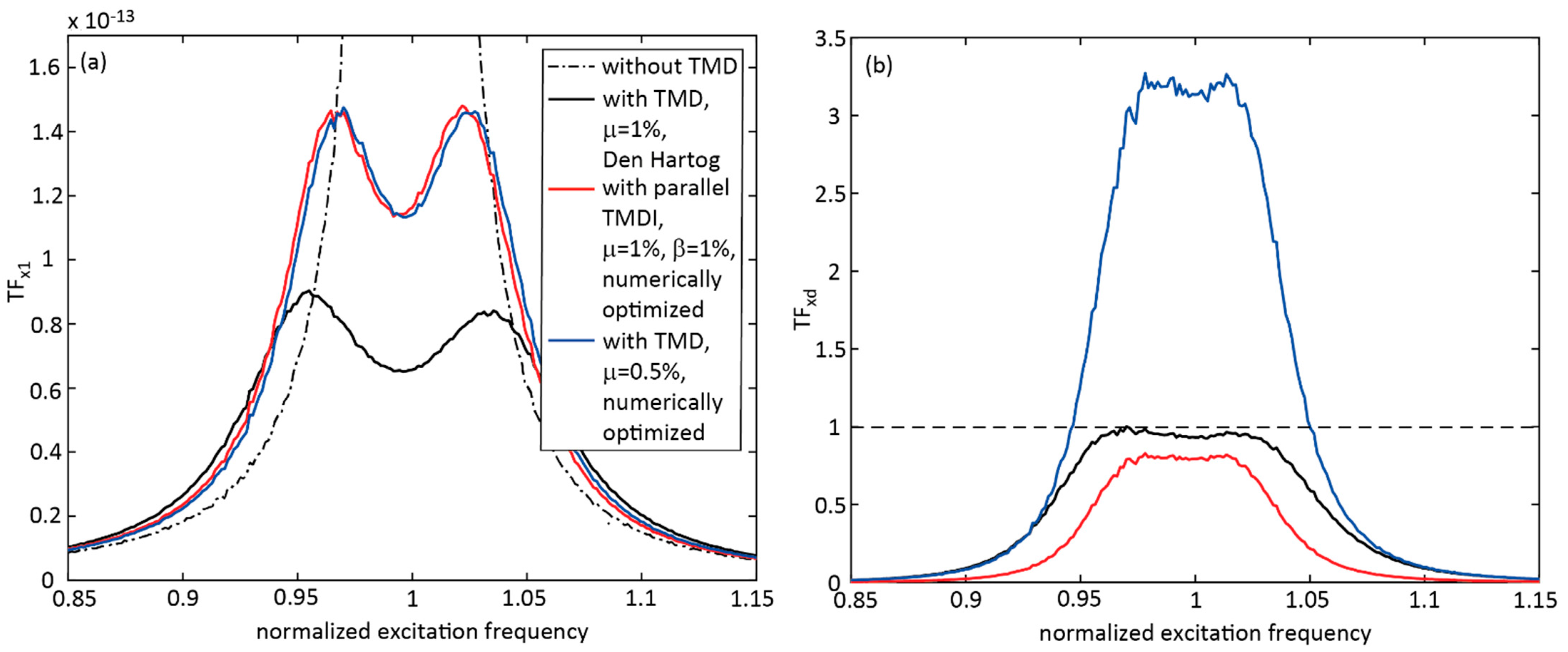
4.2. TMDI with Inerter in Parallel to Stiffness and Viscous Damper, β = 1%, Numerically Optimized Parameters

The second case investigated the performance of the TMDI with an inerter in parallel to the stiffness and viscous damper, β = 1% and numerically optimized parameters. The results are depicted in Figure 6 and Figure 7 for harmonic and random excitations and compared to the classical TMD with same mass ratio and Den Hartog parameters and the TMD with μ = 0.5% and numerically optimized parameters. It can be seen that the classical TMD still performed significantly better than the TMDI with β = 1% and numerically optimized parameters. Notice that the left peak of the classical TMD is slightly higher than the right peak because ζ 1 = 1% was used for the computations, but the Den Hartog formulae assume ζ 1 = 0%. Furthermore, it was observed that mitigation of the primary structure due to the TMDI was approximately equal to that due to a TMD with half mass. Needless to say, the relative motion of the TMD with half mass was significantly greater than that of the TMD with μ = 1% and that of the TMDI with μ = 1% and β = 1%.

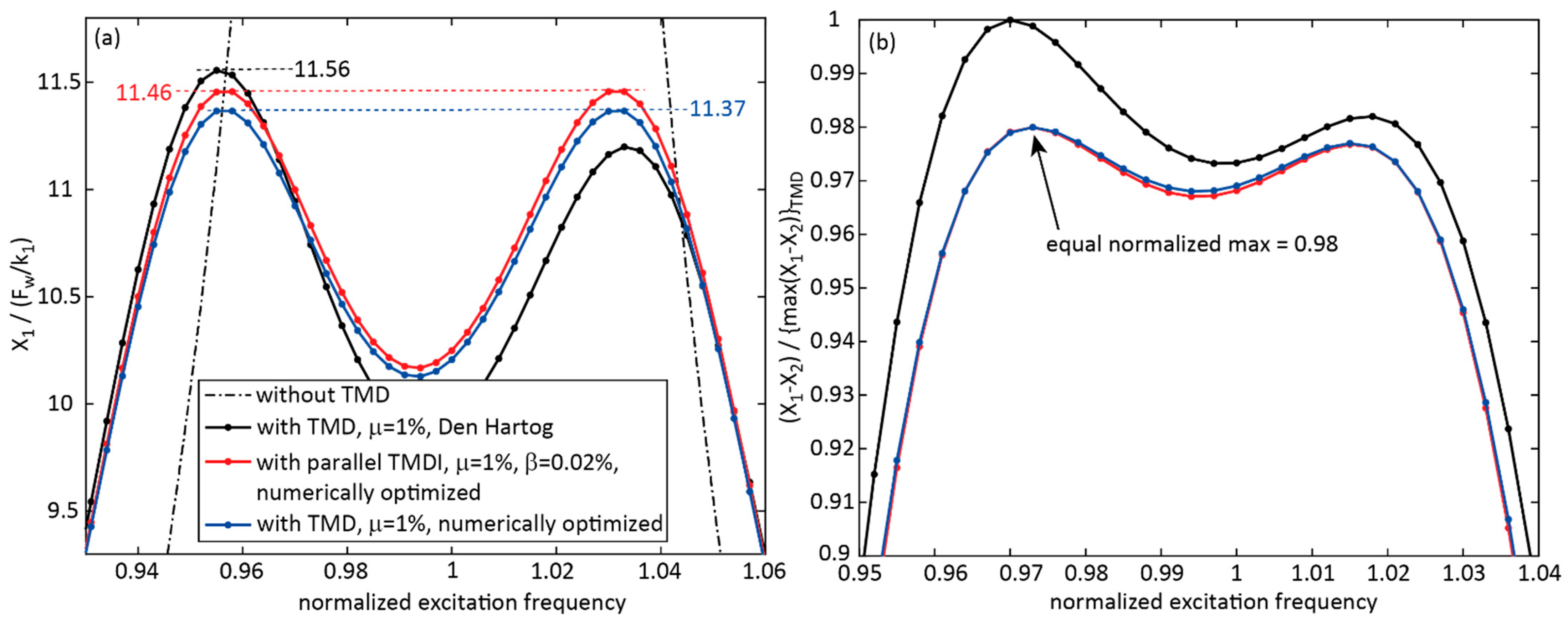
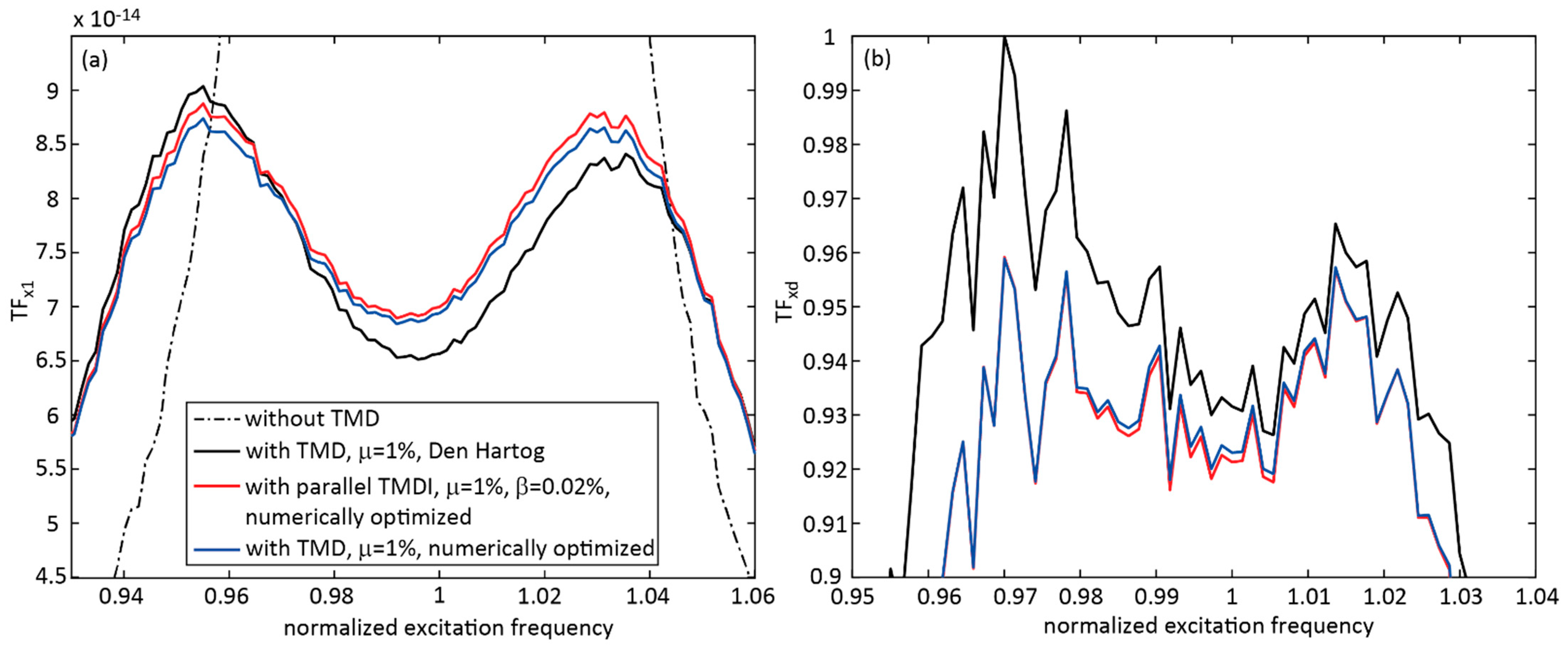
4.3. TMDI with Inerter in Parallel to Stiffness and Viscous Damper, β = 0.02%, Numerically Optimized Parameters

The third case investigated how the far smaller inertance ratio of β = 0.02% influenced the performance of the TMDI. For this case, only numerically optimized TMDI parameters were considered, as the first case demonstrated that the TMDI parameters set according to [33] led to a far suboptimal tuning. The results of the TMDI with β = 0.02% and numerically optimized parameters are plotted in Figure 8 and Figure 9 for harmonic and random excitations and compared to the results of the TMD ( μ = 1%) with Den Hartog parameters and the TMD ( μ = 1%) with numerically optimized parameters. Figure 8 shows that the TMDI with the very small inertance ratio of β = 0.02% and numerically optimized parameters led to a far better performance than the numerically optimized TMDI with β = 1%. However, the primary structure displacement was slightly worse ( X 1 / ( F w / k 1 ) ) = 11.46) than for the numerically optimized TMD with the same mass ratio ( X 1 / ( F w / k 1 ) ) = 11.37). A difference in their maximum relative motions could not be observed.

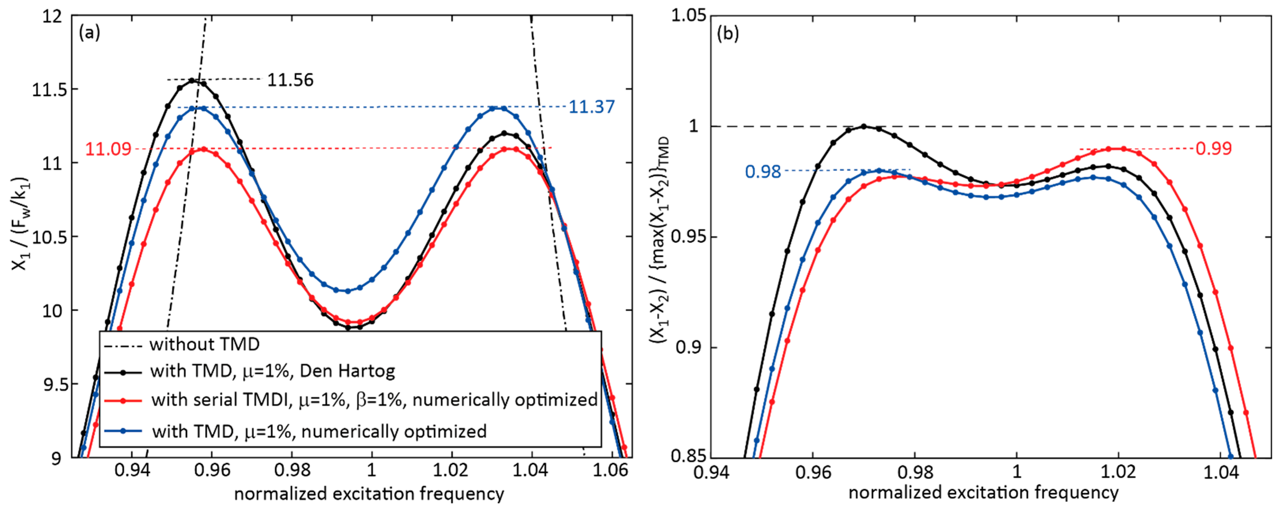
4.4. TMDI with Serial Arrangement of Stiffness, Inerter and Viscous Damper, β = 1% and 0.02%, Numerically Optimized Parameters

The fourth case considered the TMDI with a serial arrangement of stiffness, inerter and viscous damper. First, the TMDI with μ = 1%, β = 1% and numerically optimized parameters was considered. The results for harmonic excitation depicted in Figure 10 demonstrate that this TMDI slightly reduced the primary structure displacement by (11.37–11.09)/11.37 = 2.5%, while the TMDI relative motion was almost the same. However, it was also observed that this TMDI topology with β = 1% did not show the envisaged three-degrees-of-freedom response characteristics; see Equation (12). This means that the serial arrangement of stiffness, inerter and viscous damper does not make sense for great inertance ratios. Therefore, the performance of the TMDI with serial topology but with the far smaller inertance ratio of β = 0.02% was analyzed next.
Figure 11 and Figure 12 depict the normalized primary structure displacements and damper relative motions due to the numerically optimized TMDI with μ = 1% and β = 0.02%, the classical TMD ( μ = 1%), Den Hartog tuning and the numerically optimized two half TMDs, each with μ = 0.5%, for harmonic and random excitations. For the case of harmonic excitation, the theoretical model of the TMDI and the physical model of the fly wheel were computed; for random excitation, the physical model only was computed, which was numerically more robust because it avoids the zeros in the fourth row of the mass matrix of the theoretical TMDI model (12). It was observed that the additional degree of freedom due to the serial arrangement of stiffness, inerter and viscous damper evoked the desirable three-degrees-of-freedom system response if the inertance ratio was small. Remember that this response characteristic was not observed for the same TMDI topology with β = 1%; see Figure 10. The simulation results shown in Figure 11 and Figure 12 demonstrate that the use of the inerter enhanced the mitigation of the primary structure response if the inerter topology and tuning were selected to evoke an additional degree of freedom and the associated TMDI parameters were numerically optimized. For harmonic excitation, the improvements were (11.56–9.50)/11.56 = 17.8% and (10.31–9.50)/10.31 = 7.9%, respectively, compared to the classical TMD and two half TMDs, respectively. Similar results can be found in [35,36]. Another advantage of this TMDI solution is the reduced damper relative motion compared to the two half TMD solution, where the masses were not fully activated at one specific excitation frequency because of the different natural frequency tunings of the two half TMDs. Of course, these benefits of this TMDI solution must be related to the additional efforts that are needed for the technical realization of the serial arrangement of stiffness, frictionless inerter and viscous damper.

5. Conclusions

This study investigated the mitigation efficiencies of a TMDI and TMD with the same mass ratios for harmonic and random excitations. Two TMDI topologies were considered, i.e., the inerter in parallel to the spring and viscous damper of the damper mass and the serial arrangement of spring, inerter and viscous damper in parallel to the main spring of the damper mass. The TMDI was computed for the mass ratio of 1%, the commonly used inertance ratio of 1% and the far smaller inertance ratio of 0.02%, with analytical parameters set according to values described in the literature and numerically optimized parametric values. The results for harmonic and random excitation demonstrated:
  • That the TMDI with parallel stiffness, damping and inerter and with the typical inertance ratio of 1% led to greater normalized primary structure displacement than the TMD; for harmonic excitation the maximum displacement response was 27.47% greater than the response due to the classical TMD with Den Hartog parameters;
  • That the parallel TMDI with the very small inertance ratio of 0.02% led to approximately the same primary structure displacement response as the classical TMD with numerically optimized parameters;
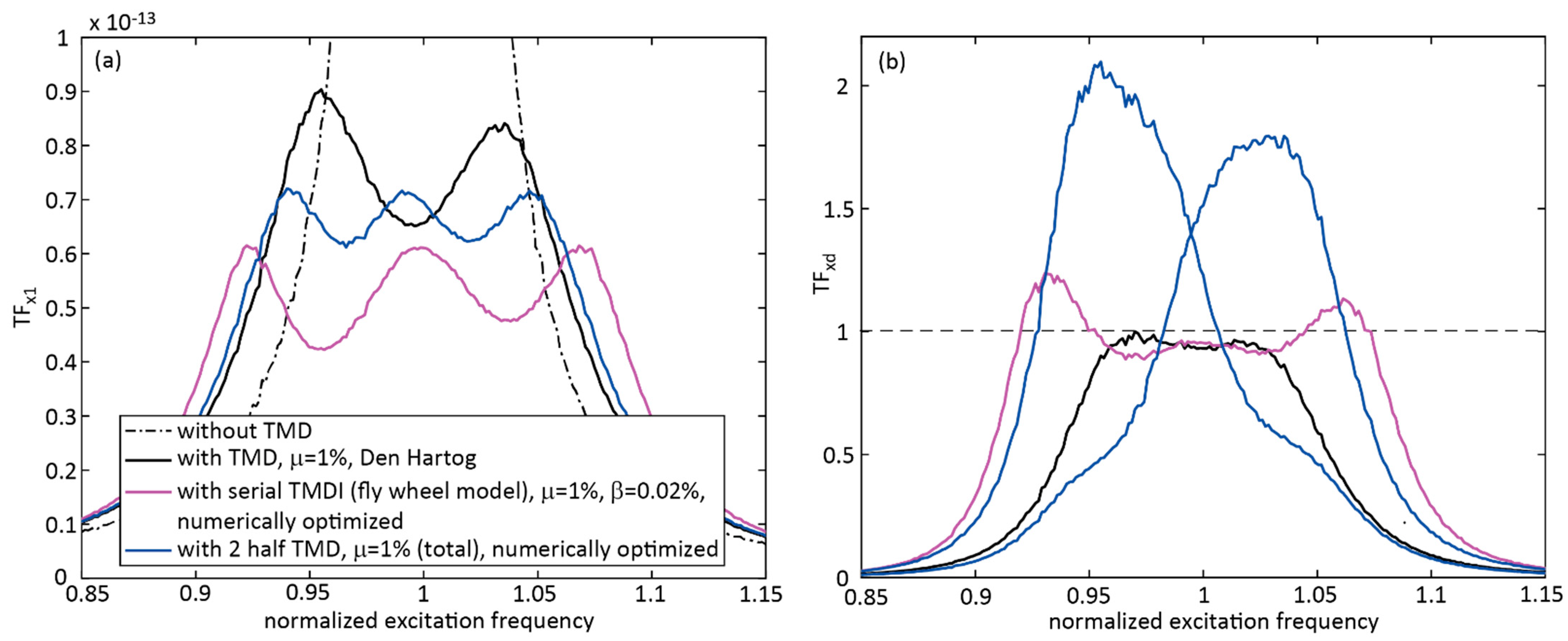
  • That if the inertance ratio of the serial TMDI is too big, then the favorable three-degrees-of-freedom dynamics are not observed and;
  • That the TMDI with the serial arrangement of spring, inerter and viscous damper besides the main spring of the damper resulted in an additional degree of freedom. This system, with numerically optimized parameters and the small inertance ratio of of 0.02%, performed better than the TMD; for harmonic excitation, the structural displacement response was additionally reduced by 17.82%. This benefit must be related to the technical efforts that are needed to realize the serial arrangement of a spring, an inerter and a viscous damper without producing undesirable significant friction in the inerter and the connections between these three elements.

Author Contributions

Conceptualization, F.W., F.B., J.D. and C.B.; methodology, F.W., F.B. and J.D.; software, F.W. and F.B.; formal analysis, F.W. and F.B.; writing—original draft preparation, F.W., F.B., J.D. and C.B.; writing—review and editing, F.W. and F.B.; project administration, F.W., F.B., J.D. and C.B. All authors have read and agreed to the published version of the manuscript.

Funding

This research received funding from the Stiftung Maurer Söhne.

Institutional Review Board Statement

Not applicable.

Informed Consent Statement

Not applicable.

Data Availability Statement

The data presented in this study are available on request from the corresponding author.

Acknowledgments

The authors acknowledge the support of Maurer SE, Stiftung Maurer Söhne and OTH Regensburg.

Conflicts of Interest

The authors declare no conflict of interest.

References

  1. Den Hartog, J.P. Mechanical Vibrations; McGraw-Hill Book Company, The Maple Press Company: York, PA, USA, 1934. [Google Scholar]
  2. Asami, T.; Nishihara, O.; Baz, A.M. Analytical solutions to H∞ and H2 optimization of dynamic vibration absorber attached to damped linear systems. J. Vib. Acoust. 2020, 124, 284–295. [Google Scholar] [CrossRef]
  3. Weber, F.; Obholzer, F.; Huber, P. Model-based TMD Design for the Footbridge “Inwilerstrasse” in Switzerland and its Experimental Verification. In Proceedings of the Footbridge International Conference, Madrid, Spain, 7–9 September 2020. [Google Scholar]
  4. Rezende, F.; Brunet, O., Jr.; Diniz Varela, W.; Pereira, A.; Carvalho, E. Evaluation of TMD Performance in Footbridges Using Human Walking Probabilistic Models. Vibration 2021, 4, 21. [Google Scholar] [CrossRef]
  5. Poon, D.; Shieh, S.-S.; Joseph, L.; Chang, C.-C. Structural Design of Taipei 101, the World’s Tallest Building. In Proceedings of the CTBUH 2004 Seoul Conference, Seoul, Korea, 10–13 October 2004; pp. 271–278. [Google Scholar]
  6. Weber, F.; Huber, P.; Spensberger, S.; Distl, J.; Braun, C. Reduced-mass Adaptive TMD for Tall Buildings Damping. Int. J. High-Rise Build. 2019, 8, 117–123. [Google Scholar]
  7. HIVOSS. Design of Footbridges, Guidelines; RFS2-CT-2007-00033. Footbridge_Guidelines_EN03-08; FIB: Lausanne, Switzerland, 2008. [Google Scholar]
  8. HIVOSS. Design of Footbridges, Background Information; RFS2-CT-2007-00033. Footbridge_Background_EN02.doc-12.11; FIB: Lausanne, Switzerland, 2008. [Google Scholar]
  9. ISO 10137; Bases for Design of Structures—Serviceability of Buildings and Walkways against Vibrations. ISO: Geneva, Switzerland, 2007.
  10. Weber, F. Dynamic characteristics of controlled MR-STMDs of Wolgograd Bridge. Smart Mater. Struct. 2013, 22, 095008. [Google Scholar] [CrossRef]
  11. Meng, F.; Wan, J.; Xia, Y.; Ma, Y.; Yu, J. A Multi-Degree of Freedom Tuned Mass Damper Design for Vibration Mitigation of a Suspension Bridge. Appl. Sci. 2020, 10, 457. [Google Scholar] [CrossRef] [Green Version]
  12. Zhai, W.; Han, Z.; Chen, Z.; Ling, L.; Zhu, S. Train–track–bridge dynamic interaction: A state-of-the-art review. Veh. Syst. Dyn. 2019, 57, 984–1027. [Google Scholar] [CrossRef] [Green Version]
  13. Chapain, S.; Aly, A.M. Vibration attenuation in wind turbines: A proposed robust pendulum pounding TMD. Eng. Struct. 2021, 223, 111891. [Google Scholar] [CrossRef]
  14. Chen, Y.; Jin, X.; Luo, M.; Cheng, P.; Wang, S. Vibration reduction methods of large-scale wind turbines based on system-TMD coupled algorithm. Ocean. Eng. 2021, 226, 108832. [Google Scholar] [CrossRef]
  15. Kim, S.-M.; Wang, S.; Brennan, M.J. Robust broadband vibration control of a flexible structure using an electrical dynamic absorber. Smart Mater. Struct. 2011, 20, 75002. [Google Scholar] [CrossRef]
  16. Chen, Z.Y.; Jiang, R.; Wang, R.Y.; Chen, T. Active TMD systematic design of fuzzy control and the application in high-rise buildings. Earthq. Struct. 2021, 21, 577–585. [Google Scholar]
  17. Weber, F. Semi-active vibration absorber based on real-time controlled MR damper. Mech. Syst. Signal Processing 2014, 46, 272–288. [Google Scholar] [CrossRef]
  18. Weber, F.; Distl, H.; Fischer, S.; Braun, C. MR Damper Controlled Vibration Absorber for Enhanced Mitigation of Harmonic Vibrations. Actuators 2016, 5, 27. [Google Scholar] [CrossRef]
  19. Wang, Y.; Wang, L.; Shi, W. Two-dimensional air spring based semi-active TMD for vertical and lateral walking and wind-induced vibration control. Struct. Eng. Mech. 2021, 80, 377–390. [Google Scholar] [CrossRef]
  20. Papageorgiou, C.; Houghton, N.E.; Smith, M.C. Experimental Testing and Analysis of Inerter Devices. J. Dyn. Syst. Meas. Control. 2009, 131, 011001. [Google Scholar] [CrossRef]
  21. John, E.D.A.; Wagg, D.J. Design and testing of a frictionless mechanical inerter device using living-hinges. J. Frankl. Inst. 2019, 356, 7650–7668. [Google Scholar] [CrossRef] [Green Version]
  22. Smith, M.C.; Wang, F.-C. Performance Benefits in Passive Vehicle Suspensions Employing Inerters. Veh. Syst. Dyn. 2004, 42, 235–257. [Google Scholar] [CrossRef] [Green Version]
  23. Baduidana, M.; Kenfack-Jiotsa, A. Optimal design of inerter-based isolators minimizing the compliance and mobility transfer function versus harmonic and random ground acceleration excitation. J. Vib. Control. 2020, 27, 1297–1310. [Google Scholar] [CrossRef]
  24. Krenk, S.; Høgsberg, J. Tuned resonant mass or inerter based absorbers: Unified calibration with quasi-dynamic flexibility and inertia correction. Proc. R. Soc. A 2016, 472, 20150718. [Google Scholar] [CrossRef] [Green Version]
  25. Chen, M.; Hu, Y. Inerter and Its Application in Vibration Control Systems; Springer Nature Singapore Pte Ltd. and Science Press: Beijing, China, 2019; Volume 472, p. 20150718. ISBN 978-981-10-7088-4. [Google Scholar]
  26. Krenk, S. Resonant inerter based vibration absorbers on flexible structures. J. Frankl. Inst. 2019, 356, 7704–7730. [Google Scholar] [CrossRef]
  27. Wagg, D.J. A review of the mechanical inerter: Historical context, physical realisations and nonlinear applications. Nonlinear Dyn. 2021, 104, 13–34. [Google Scholar] [CrossRef]
  28. Lazar, I.F.; Neild, S.A.; Wagg, D.J. Using an inerter-based device for structural vibration suppression. Earthq. Eng. Struct. Dyn. 2014, 43, 1129–1147. [Google Scholar] [CrossRef] [Green Version]
  29. Lara-Valencia, L.A.; Farbiarz-Farbiarz, Y.; Valencia-González, Y. Design of a Tuned Mass Damper Inerter (TMDI) Based on an Exhaustive Search Optimization for Structural Control of Buildings under Seismic Excitations. Shock. Vib. 2020, 2020, 8875268. [Google Scholar] [CrossRef]
  30. Jalali, H.H.; Maziar Farzam, F. Inerter-Connected Double Tuned Mass Damper for Passive Control of Buildings under Seismic Excitation. Period. Polytech. Civ. Eng. 2022, 66, 421–432. [Google Scholar]
  31. Marian, L.; Giaralis, A. Optimal design of a novel tuned mass-damper-inerter (TMDI) passive vibration control configuration for stochastically support-excited structural systems. Probabilistic Eng. Mech. 2014, 38, 156–164. [Google Scholar] [CrossRef]
  32. Giaralis, A.; Petrini, F. Optimum design of the tuned mass-damper-inerter for serviceability limit state performance in wind-excited tall buildings. Procedia Eng. 2017, 199, 1773–1778. [Google Scholar] [CrossRef]
  33. Giaralis, A.; Petrini, F. Wind-induced vibration mitigation in tall buildings using the tuned mass-damper-inerter (TMDI). J. Struct. Eng. 2017, 143, 4017127. [Google Scholar] [CrossRef]
  34. Zhang, Z.; Fitzgerald, B. Tuned mass-damper-inerter (TMDI) for suppressing edgewise vibrations of wind turbine blades. Eng. Struct. 2020, 221, 110928. [Google Scholar] [CrossRef]
  35. Barredo, E.; Larios, M.; Mayén, J.; Flores-Hernández, A.A.; Colín, J.; Arias-Montiel, M. Optimal design for high-performance passive dynamic vibration absorbers under random excitation. Eng. Struct. 2019, 195, 469–489. [Google Scholar] [CrossRef]
  36. Barredo, E.; Larios, M.; Colín, J.; Mayén, J.; Flores-Hernández, A.A.; Arias-Montiel, M. A novel high-performance passive non-traditional inerter-based dynamic vibration absorber. J. Sound Vib. 2020, 485, 115583. [Google Scholar] [CrossRef]
  37. Alotta, G.; Failla, G. Improved inerter-based vibration absorbers. Int. J. Mech. Sci. 2021, 192, 106087. [Google Scholar] [CrossRef]
  38. Dai, J.; Xu, Z.D.; Gai, P.P. Tuned mass-damper-inerter control of wind-induced vibration of flexible structures based on inerter location. Eng. Struct. 2019, 199, 109585. [Google Scholar] [CrossRef]
  39. Weber, F.; Huber, P.; Borchsenius, F.; Braun, C. Performance of TMDI for Tall Building Damping. Actuators 2020, 9, 139. [Google Scholar] [CrossRef]
  40. Meirovitch, L. Fundamentals of Vibrations; McGraw-Hill: New York, NY, USA, 2001. [Google Scholar]
Figure 1. (a) Multi-degree-of-freedom system with TMDI at the anti-node position of the first bending mode. (b) Conventional TMDI with target structural mode (modeshape factor 1). (c) Classical TMD with target structural mode (modeshape factor 1). (d) TMDI with serial arrangement of stiffness, inerter and viscous damper with target structural mode (modeshape factor 1). (e) Two half TMDs with target structural mode (modeshape factor 1).
Applsci 12 06204 g001
Figure 2. Fly wheel (without friction) as an ideal realization of an inerter.
Applsci 12 06204 g002
Figure 3. Power Spectral Density estimate via Welch’s method of white noise excitation force (close-up of frequency range 0 Hz to 10 Hz).
Applsci 12 06204 g003
Figure 4. Performances of TMDI with inerter in parallel to stiffness and viscous damper ( μ = 1%, β = 1%, parameters as in [33]), TMD ( μ = 1%, Den Hartog parameters) and overdamped TMD ( μ = 1%) for harmonic excitation: (a) primary structure normalized displacement response and (b) normalized damper relative motion response.
Applsci 12 06204 g004
Figure 5. Performances of TMDI with inerter in parallel to stiffness and viscous damper ( μ = 1%, β = 1%, parameters as in [33]), TMD ( μ = 1%, Den Hartog parameters) and overdamped TMD ( μ = 1%) for random excitation: (a) primary structure normalized displacement response and (b) normalized damper relative motion response.
Applsci 12 06204 g005
Figure 6. Performances of TMDI with inerter in parallel to stiffness and viscous damper ( μ = 1%, β = 1%, numerically optimized parameters), TMD ( μ = 1%, Den Hartog parameters) and TMD ( μ = 0.5%, numerically optimized parameters) for harmonic excitation: (a) primary structure normalized displacement response and (b) normalized damper relative motion response.
Applsci 12 06204 g006
Figure 7. Performances of TMDI with inerter in parallel to stiffness and viscous damper ( μ = 1%, β = 1%, numerically optimized parameters), TMD ( μ = 1%, Den Hartog parameters) and TMD ( μ = 0.5%, numerically optimized parameters) for random excitation: (a) primary structure normalized displacement response and (b) normalized damper relative motion response.
Applsci 12 06204 g007
Figure 8. Performances of TMDI with inerter in parallel to stiffness and viscous damper ( μ = 1%, β = 0.02%, numerically optimized parameters), TMD ( μ = 1%, Den Hartog parameters) and TMD ( μ = 1%, numerically optimized parameters) for harmonic excitation: (a) primary structure normalized displacement response and (b) normalized damper relative motion response.
Applsci 12 06204 g008
Figure 9. Performances of TMDI with inerter in parallel to stiffness and viscous damper ( μ = 1%, β = 0.02%, numerically optimized parameters), TMD ( μ = 1%, Den Hartog parameters) and TMD ( μ = 1%, numerically optimized parameters) for random excitation: (a) primary structure normalized displacement response and (b) normalized damper relative motion response.
Applsci 12 06204 g009
Figure 10. Performances of TMDI with serial arrangement of stiffness, inerter and damper ( μ = 1%, β = 1%, numerically optimized parameters), TMD ( μ = 1%, Den Hartog parameters) and TMD ( μ = 1%, numerically optimized parameters) for harmonic excitation: (a) primary structure normalized displacement response and (b) normalized damper relative motion response.
Applsci 12 06204 g010
Figure 11. Performances of TMDI with serial arrangement of stiffness, inerter and damper ( μ = 1%, β = 0.02%, numerically optimized parameters), TMD ( μ = 1%, Den Hartog parameters) and two half TMDs ( μ = 1%, numerically optimized parameters) for harmonic excitation: (a) primary structure normalized displacement response and (b) normalized damper relative motion response.
Applsci 12 06204 g011
Figure 12. Performances of TMDI with serial arrangement of stiffness, inerter and damper ( μ = 1%, β = 0.02%, numerically optimized parameters), TMD ( μ = 1%, Den Hartog parameters) and two half TMDs ( μ = 1%, numerically optimized parameters) for random excitation: (a) primary structure normalized displacement response and (b) normalized damper relative motion response.
Applsci 12 06204 g012
Table 1. Assumed primary structure modal parameters.
Modal Mass
m 1   ( t )
Eigenfrequency
f 1   ( Hz )
Damping Ratio
ζ 1   ( % )
Stiffness Coefficient
k 1   ( MN / m )
Viscous Damping Coefficient
c 1   ( kNs / m )
50,0000.141%38.689879.65
Table 2. Parameters of the considered TMDs.
Damper TypeMass Ratio
μ   =   m 2 / m 1
TuningNatural Frequency
f 2   ( Hz )
Damping Ratio
ζ 2   ( Hz )
Stiffness Coefficient
k 2   ( kN / m )
Viscous Damping Coefficient
c 2   ( kNs / m )
TMD1%Den Hartog0.13866.03%379.2753.069
TMD1%Overdamped0.13862.3434 × 6.03%379.272.3434 × 53.069
TMD0.5%Numerically optimizedNANA191.1219.134
TMD1%Numerically optimizedNANA378.1154.648
Two half TMDs1% (total)Numerically optimized k 2 a = 178.36 kN/m c 2 a = 17.123 kNs/m k 2 b = 201.62 kN/m c 2 b = 19.463 kNs/m
Table 3. Parameters of TMDIs with an inerter in parallel to stiffness and viscous damper.
Damper TypeMass Ratio
μ   =   m 2 / m 1
Inertance Ratio
β = b / m 1
TuningNatural Frequency
f 2   ( Hz )
Damping Ratio
ζ 2   ( Hz )
Stiffness Coefficient
k 2   ( kN / m )
Viscous Damping Coefficient
c 2   ( kNs / m )
Parallel TMDI1%1%[33]0.13797.02%751.17121.66
Parallel TMDI1%1%Numerically optimizedNANA760.6476.151
Parallel TMDI1%0.02%Numerically optimizedNANA385.7754.919
Table 4. Parameters of TMDIs with a serial arrangement of stiffness, inerter and viscous damper.
Damper TypeMass Ratio
μ   =   m 2 / m 1
Inertance Ratio
β   =   b / m 1
TuningStiffness Coefficient
k 2   ( kN / m )
Stiffness Coefficient
k b   ( kN / m )
Viscous Damping Coefficient
c b   ( kNs / m )
Serial TMDI1%1%Numerically optimized347.4780.10376.288
Serial TMDI1%0.02%Numerically optimized378.177.640250.441
Serial TMDI (fly wheel)1%0.02%Numerically optimized377.408.104550.275
Table 5. Parameters of the fly wheel inerter device.
Mass of Housing and Gear Rod (kg)Radius of Fly Wheel (m)Thickness of Fly Wheel (m)Gear Radius of Fly Wheel (m)Mass of Fly Wheel (kg)Mass of Fly Wheel, Steel Rod, Axle (kg)
m 3   = 5000.70.280.2883388 m 4 = 3500
Publisher’s Note: MDPI stays neutral with regard to jurisdictional claims in published maps and institutional affiliations.

