1. Introduction
The software requirement analysis [
1,
2] is the basis and source of software system design and implementation, and its accuracy and completeness are the keys to determining software quality. However, in the process of compiling software project requirements specifications, manual methods are often used. In the process of requirements research, there are often inconsistencies and ambiguities in the understanding of requirements among business personnel, requirements researchers and system developers, such as omissions in requirements research or unclear business processes [
3]. This leads to fatal errors in the design of subsequent system functional modules and greatly increases the projected R & D cost [
4]. At the same time, the manually prepared software requirements specification documents are mainly for computer professionals. Their readability is poor, and it is difficult for business personnel to understand. As a result, business personnel cannot effectively confirm whether the requirements specification truly reflects the business requirements. In the final development process, there are often a large number of requirements changes and rework, resulting in a significant increase in development time and cost. Finally, the manually prepared requirements specifications are cumbersome, error prone and make it difficult to iterate the version.
At present, the preparation methods of requirements specification documents mainly include the manual preparation of Unified Modeling Language (UML), generation of requirements specifications based on extraction rules [
5,
6] and automatic generation of requirements specifications based on natural language processing [
7]. Although manual preparation has a strong personalized customization ability to generate demand specifications, it is usually difficult to solve the problems of cumbersome manual preparation, being error prone and difficulty communicating effectively with business personnel, which are easily affected by the subjective ability of the writer [
8]. The requirement specification generation method based on extraction rules can effectively extract the requirement specification information from the text, but the corresponding extraction rules will be slightly different for different functional requirements. Theoretically, the formulation of extraction rules cannot cover all software scenarios.
The development of natural language processing (NLP) technology provides a new idea for the automatic extraction of requirements specifications. On the one hand, it can effectively improve the efficiency of the formation of software requirements specifications; on the other hand, it can effectively avoid the manual errors of the writer. At present, the application of NLP in English knowledge extraction has been relatively mature and effective, and there are also applications in the field of Chinese knowledge extraction [
9,
10]. In the software requirements specification document, the most involved parts are user roles, functional requirements, data tables and business processes. Business process is often the flow process of data tables and operation instructions. Function, data and the relationship between them are the core of software requirements specification. If NLP technology can be used to quickly and automatically extract relevant functions, data tables and effectively express the relationship between them, it will effectively improve the efficiency and level of compiling software requirements specification documents.
Based on the above problems, this study focuses on the inconsistency, ambiguity, weak readability, and cumbersome and error prone problems in the preparation of software requirements specification documents and defines the automatic generation model of software requirements specification BiLSTM-CRF-KG (Bi-Directional Long Short-Term Memory-Conditional Random Field-Knowledge Graph) by borrowing the knowledge extraction ability of NLP, the visual expression of a knowledge graph and the ability to remove ambiguity.
The main contributions and innovations of the study are as follows:
Introducing natural language processing and knowledge graph technology into the software requirements specification. Furthermore, this paper, using the knowledge unity and visual expression characteristics of a knowledge graph, can effectively eliminate the fuzziness, ambiguity and possible lack of research in the preparation of software requirements specification, which shorten the level of business understanding of requirements analysts and business personnel.
Improving the traditional U/C matrix into an S/U/C matrix, which is used to effectively express the data form flow relationship between the creator of the data form, the sender and the user. It can effectively solve the problems of function omission, lack of data form and fuzzy business process in the process of some demand research and analysis.
This study conducts simulation experiments on 150 real software system business requirements, and experimental result shows that the BiSLTM-CRF-KG model can obtain 96.48% functional entity recognition accuracy directly from the original corpus, which is more than 5 percentage points higher than the classical BiSLTM-CRF, IDCNN-CRF and CRF++ models, and has a good performance in different kinds of data sets.
This paper consists of five sections.
Section 1 introduces the research background and significance, and briefly introduces the research content.
Section 2 is related work and research.
Section 3 describes the theory and framework process of BiLSTM-CRF-KG.
Section 4 is the simulation experiment and its results.
Section 5 is the conclusion and future work.
2. Related Work
A range of methods have been introduced in previous research to (semi-)automatically extract functional requirements written in natural language text.
Ghosh et al. [
11] used the method of semantic analysis to extract the intermediate representation table, then used a set of heuristic post-processing rules to transform the intermediate representation table into a formal specification. Roth et al. [
12] proposed the technology from semantic role annotation to high-level ontology to describe the concepts and relationships of static software functions. However, this technology cannot capture more fine-grained structured information in the requirements specification. Zhou, ZD et al. [
13] proposed mathematical methods to analyze customer needs from the perspective of information, and to obtain, classify and process the information. Li, Y et al. [
14] used NLP technology to match the defined pattern to achieve information extraction. However, they did not analyze the semantics of fine-grained elements. Using machine learning, natural language processing, semantic analysis and other methods, Yinglin Wang [
15] proposed a method to automatically extract the structural information of functional requirements from natural language software requirements description and compared the performance of two different named entity recognition models. However, this study only carries out the experiment at the sentence level and does not perform a comprehensive analysis of the requirements according to the text paragraph and the context information.
Pavlova et al. [
16] conducted a semantic analysis on the requirements of the Internet of Things system, increased the capacity of the Internet of Things system, ensured the sufficiency of the measurement information in the software requirements, and improved the quality of the Internet of Things system software. Li, MY et al. [
17] presented a novel approach named RENE, which employs the LSTM-CRF model for requirement entity extraction and introduces the general knowledge to reduce the demands for labeled data. However, due to the reduction of data annotation, the performance of the model was unsatisfactory. Through clustering and entry point selection, Ieva, C et al. [
18] proposed a method to automatically extract the main functions of the program and carried out feature extraction and tracking. Park, BK et al. [
19] proposed a linguistic analysis method based on the semantic analysis of the Fillmore’s textual approach. This method extracts use-cases from informal requirement specifications.
For Chinese knowledge extraction, there are also some scholars engaged in related research. Sun, X et al. [
20] proposed a method for Chinese medical named entities recognition on the combination of Chinese radicals and etymon features in the classic character-based BiLSTM-CRF (Bi-Directional Long Short-Term Memory-Conditional Random Field), which performs better than the state-of-art deep learning models in our experiment. Liu, WM et al. [
21] proposed a Chinese named entity recognition method based on rules and conditional random fields, which could effectively identify the named entities and improve the processing speed and efficiency. In addition, there is a certain practical value. Dao, AT et al. [
22] proposed an approach to improve monolingual named entity recognition systems by exploiting an existing unannotated English–Chinese bilingual corpus.
3. Structural Information Extraction Model of Functional Requirements
Aiming at the problems of inconsistency, ambiguity, being cumbersome and error prone in manually writing software requirements specifications and that which cannot be expressed visually, this study proposes a construction method of software requirements specification graph BiLSTM-CRF-KG based on the BiLSTM-CRF model and knowledge graph technology. The framework design is shown in
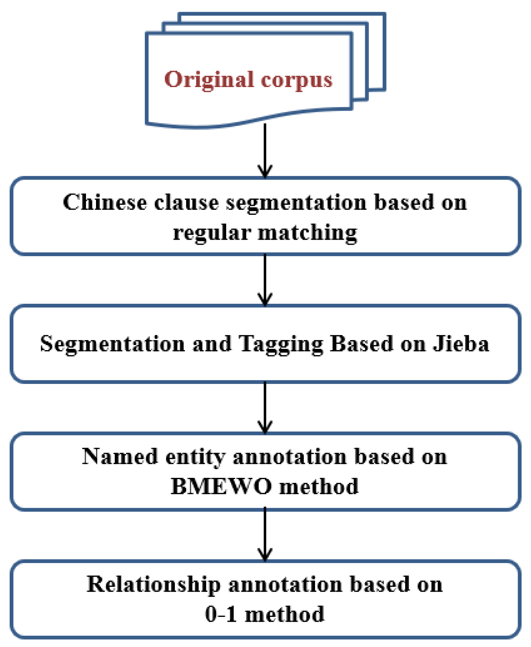
Figure 1.
The main contents of building the software requirements specification graph BiLSTM-CRF-KG are as follows:
Preprocessing of the original corpus: it mainly realizes the Chinese sentence segmentation, word segmentation, part of speech tagging, named entity and relation tagging of the original business requirements description corpus.
Entity relationship extraction: input the segmentation annotation results into the BiLSTM-CRF model to extract the relationship between functional entities and functions, then generate a preliminary entity relationship set.
Entity disambiguation and hidden relation learning: use context to disambiguate functional entities such as pronouns and abbreviations and learn the hidden relation between functional entities in the preliminary entity relation set, so as to further optimize the entity relation set.
Generation of functional structure graph: use the hierarchical structure of multi tree to transform the optimized entity relationship set into the demanded relationship tree. Then, using the breadth first search strategy, the requirement relationship tree is transformed into a (parent function, parent–child relationship, child function) function structure triplet, which is saved in the neo4j database to realize the automatic embedding of the function structure graph.
Study the method of converting the traditional U/C matrix into the S/U/C matrix to reflect the real flow relationship between the creator/sender/user of the business data table.
Transform the business data table description into the S/U/C matrix.
Use the relationship between the S/U/C matrix mapping function and the data table to generate the (function-create/send/use relationship-data table) triplet and save it in the neo4j database to realize the automatic embedding of the function-data graph.
Integrate the function structure graph and function-data graph to generate the software requirements specification graph.
3.1. Preprocessing of the Original Corpus
The steps of preprocessing the original corpus are shown in
Figure 2.
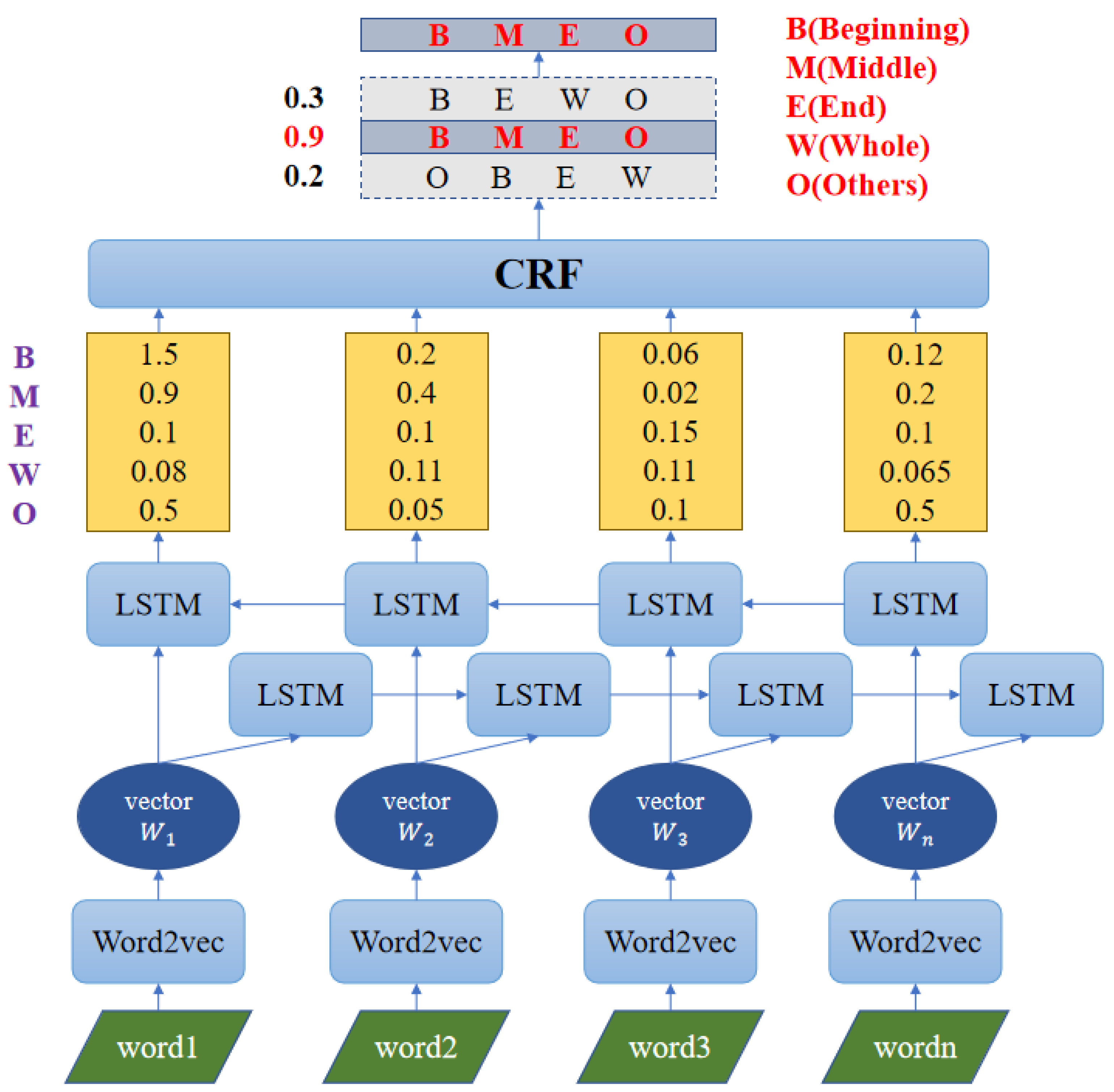
Before entity recognition and relation extraction, this project must carry out sentence segmentation, word segmentation and part of speech tagging on the original corpus.
First of all, Chinese sentence segmentation needs to be carried out, which is based on regular matching on the original corpus. The characteristic characters should be counted at the end of Chinese text sentences. A regular expression group should be constructed that matches a complete sentence, and it is utilized as the input parameter of the split() segmentation function to carry out Chinese sentence segmentation.
Secondly, the Jieba tool is utilized to segment Chinese words and label parts of speech of each clause. This is because a part of speech is used in the following, named entity pruning and disambiguation operations. The word attribute of each participle represents the content of the participle, and the flag attribute represents the participle’s part of speech.
Then, the BMEWO named entity and 0-1 relation dimension are utilized for each participle. BMEWO annotation is the most common method of naming entity annotation, among which B represents the entity start word, M stands for the entity intermediate word, E represents the entity ending word, W represents the entity whole word and O represents the non-entity word. For the relational words, the 0-1 annotation method is mainly used. Among them, 1 represents the relation word and 0 represents the non-relational word.
Finally, the original corpus is divided into independent words, and the features of each word are recorded as
.
Among them,
represents the content of word segmentation,
represents the part of speech of word segmentation,
e represents the attribute of named entity and
r represents the attribute of relation. The implementation of this part is shown in Algorithm 1.
| Algorithm 1. Preprocessing of the Original Corpus |
Input: Corpus
Output:
1: sentences = Corpus.split()
2: i = 0
3: for s in sentences do
4: temp = jieba.cut(s)
5:
6:
7:
8:
9: i++
10: end for
11: return w |
3.2. Named Entity Recognition and Relation Extraction
In this study, the BiLSTM-CRF model is used for named entity recognition and relationship extraction. The BiLSTM-CRF model is a combination of the traditional BiLSTM and CRF models, which can not only consider the correlation between sequences as CRF, but also have the feature extraction and fitting ability of LSTM. Among them, BiLSTM is composed of forward LSTM and backward LSTM. The structure of the BiLSTM-CRF model is shown in
Figure 3.
The LSTM model is composed of input words , cell state , temporary cell state , hidden state , forgetting gate , memory gate and output gate . The calculation process of LSTM can be summarized as follows: by forgetting and memorizing the information in the cell state, the useful information for the subsequent calculation can be transferred, while the useless information is discarded, and the hidden layer state will be the output at each time step. Forgetting, memory and output are controlled by forgetting gate , memory gate and output gate , respectively, which are calculated by the hidden layer state of the last time and the current input .
The traditional LSTM named entity recognition model cannot get the basic information from the back to the front when coding each statement data. In the classification of more fine-grained word segmentation, such as the classification of different degrees of commendatory or derogatory emotional words, we need to pay special attention to the logical relationship between each word. BiLSTM integrates two groups of LSTM layers with opposite directions, one in sentence order and the other in reverse order, so that words contain both historical information and future information, which are more conducive to capturing two-way semantic dependence.
The process of named entity recognition is shown in
Figure 4. When each word segment in a sentence is input into the BiLSTM-CRF model, the embedding layer will map it to an initial word vector, and then transfer it to the BiLSTM layer to obtain the forward and backward vectors of the sentence. These forward and backward vectors are spliced as the hidden state vector of the current vocabulary. Although a softmax layer can be used to predict the label of each hidden vector h directly, the predicted label does not consider the information of the front and back labels.
For example, when the named entity attribute of
is “O”, the named entity attribute of
cannot be “M” and “E”. Therefore, this project inputs a hidden state vector hidden to the CRF layer, and then gives more reasonable named entity recognition and relationship extraction results by combining current input information and context information. The result of the named entity recognition is recorded as
. The implementation of this part is shown in Algorithm 2.
| Algorithm2. Entity relationship extraction based on BiLSTM-CRF |
Input: w
Output:
1: pw = BiLSTM-CRF(w)
2: i = 0; temp=’’; j=0;
3: for c in pw do
4: c.flag == ‘x’ && c.e != ‘O’ then
5:
6: c.e == ‘B’ then
7:
8:
9: else
10:
11: end if
12: end if
13: end if
14: i++
15: end for
16: for d in pw do
17: d.e == ‘W’ then
18: j++;
19: else d.e == ‘B’ || d.e == ‘M’ then
20:
21: else d.e == ‘E’ then
22: j++;temp = ‘’;
23: d.r == 1 then
24: j++;
25: end if
26: end for
27: return e |
3.3. Entity Disambiguation and Hidden Relation Learning
The structure of entity disambiguation and hidden relation learning is shown in
Figure 5.
Firstly, based on the part of speech that is word segmentation, the experiment disambiguates the recognition result of the named entity of word segmentation. Secondly, the entity and relationship of the disambiguated results are generated based on regular matching. Thirdly, after the entity relation set is generated, we need to align the abbreviations and pronouns, and further learn the hidden relations in the original corpus, so as to deeply mine the structured information of the functional requirements.
3.3.1. Word Sense Disambiguation Model Based on Part of Speech
In the BiLSTM-CRF model, although CRF is based on context information, it can obtain reasonable named entity labels. However, there are some errors in the entity label. For example, numbers or punctuation marks are often mistakenly identified as “B” labels (relational words usually do not have such problems because they are mostly composed of single words). Therefore, some parts of speech features are utilized as a screening condition to correct the labels which should be marked as named entity words, but not be positioned as named entity words. The correction definition is shown in Formula (2).
After the word sense disambiguation model, if the symbol marked as “B” is corrected to “O”, there will be no word marked as “B” in front of the segmentation labeled as “M” or “E”. Therefore, the output of the model needs to be filtered by the CRF model to prevent unreasonable entity tag collocation.
3.3.2. Entity Generation Based on Regular Matching
After word sense disambiguation, the named entity label of each participle can be obtained. In this project, entity generation based on regular matching is carried out according to entity and relationship composition rules, and the generation rules are shown in Formulas (3) and (4).
A named entity is composed of a participle marked with ‘B’, several participles marked with ‘M’ and a participle marked with ‘E’; or, it can also be composed of a participle marked with ‘W’.
Here, means that the item is an entity and means that the item is a relationship. Because of the sequence of entities and relations in sentences, they cannot be stored separately.
3.3.3. Alignment of Abbreviations and Pronouns Based on Context Information
In the description of business requirements, abbreviations and pronouns are common. For this kind of entity, this project needs to align abbreviations and pronouns based on context information. For the demonstrative pronoun, the “principle of proximity” is adopted to correct the demonstrative pronoun to the nearest entity before the entity. The definition is shown in Formula (5).
For abbreviations, the content can be considered as the entity contained in the subject in the previous sentence. If the subject in the previous sentence does not contain an entity, it is considered as the nearest entity, as shown in Formula (6).
3.3.4. Entity Hiding Relation Learning Based on Punctuation and Number
In the process of relation extraction, it is not enough to extract key words. Relationships are often hidden within and between sentences. The most representative is the order and hierarchy information hidden by numbers and punctuation. If it is not fully utilized in relation extraction, it is easy to break the relation chain. Therefore, the use of hidden relation words is considered in this project, such as punctuation marks and numbers for relation extraction and disambiguation.
Numerical ranking is often seen in the requirement description corpora, which includes both juxtaposition and inclusion. For example, “(1)” and “(2)” represent juxtaposition, while the order of “1”, “(1)” or “①” represents inclusion. Therefore, the extraction rules for the hidden relationship of numbers are shown in Formula (7).
Every time a number such as a serial number appears, a relation node needs to be added to the e set. It is assumed that the primary functions in the corpus are labeled with “1”, “2”. The secondary functions are labeled with “(1)” “(2)”. The three-level functions use labels such as “①” and “②”. Then, when the number level is the same, it represents the parallel relationship between the next entity and the previous entity; when the number levels are different, the number represents the inclusion relationship between the next entity and the previous entity at the same level.
Punctuation, as the connector of two sentences or phrases, also carries the hidden entity relationship. In this project, the enumeration method is used to extract relations, and the definition of rules is shown in Formula (8).
Every time a punctuation mark appears, it is necessary to add a relation node to the
e set. When “、” appears in the sentence, it represents the juxtaposition between the next entity and the previous entity of the same level, so the type of the entity needs to be the same as the previous entity; when “。” or “;” is in the sentence, the end relation node is inserted to facilitate the construction and extraction of triples. The implementation of this part is shown in Algorithm 3.
| Algorithm3. Entity disambiguation and hidden relation learning |
Input: e, refword, abbword, includeword, andword, numericsign
Output:
1: for i = 0: do
2: then
3: =
4: then
5: = subject(i)
6: end if
7: end for
8: for i = 0: do
9: then
10: =
11: then
12: e.delete(i)
13: end if
14: end for
15: for i = 0: do
16: isnumeric() then
17: =1 && not in numericsign then
18: e.splice(i+1,1,{word:include,type:1})
19: else =1 && in numericsign then
20: e.splice(i,1,{word:include,type:1})
21: end if
22: end if
23: end for
24: return e |
3.4. Generation of Functional Structure Graph
3.4.1. Generation of Requirement Relation Tree
Since the entity relation set is actually a sequential sequence, the extraction sequence can be generated based on the idea of stack, so as to establish the requirement relation tree RTree.
First, start to stack from the first element of the entity relationship set, that is, the begin node, until the end node is encountered. Then, start to build the requirement relation tree according to the elements in the stack: perform the stack out operation on the elements in the stack successively, assuming that the stack out element is ei. If ei.type = 0, traverse the RTree of the requirement relation tree. If the ei already exists in the requirement relation tree, it is located on the tree node. Then continue to jump below, if the next ei.type = 0, the extraction sequence error. If ei.type = 1, record the relationship node information, and then continue to jump below. If the next ei.type = 1, the extraction sequence is wrong.
In this way, a part of the requirement relation tree RTree is obtained. Repeat the above operations again, and finally obtain the complete requirement relation RTree. The name of the software system is the root node of the requirement relation tree, and each relation node is both the child node of the parent function and the parent node of the child function.
3.4.2. Embedding of Functional Structure Graph
In the embedded part of the function structure graph, the search is carried out layer by layer according to the breadth first strategy of the tree, and the triples are constructed step by step. The head node is , the relationship node is , and the tail node is .
After generating the function-function triplet, this study uses the py2neo module of Python to embed the function structure graph and save it to the neo4j database. The implementation of this part is shown in Algorithm 4.
| Algorithm4. Generation of functional structure graph |
Input: e
Output:
1: tree = {}
2: for i = 0: do
3: while do
4:
5: i++
6: end while
7: while do
8: if then
9: if then
10: if then
11: relationnode = TREE_CREATENODE(stack.pop)
12: end if
13:
14: TREE_ADDNODE(node,)
15: end if
16: end if
17: end while
18: stack.empty()
19: end for
20: tree = Concact_Tree()
21: relationNode = BFS(tree.root,type=1)
22: for node in relationNode do
23: triple.append((FatherNode(node),node,ChildNode(node)))
24: end for
25: Function_Function_KG = triple2KG(triple)
26: return Function_Function_KG |
3.5. Method of Converting Traditional U/C Matrix into S/U/C Matrix
The U/C matrix can only reflect the relationship between creator and user, but it cannot reflect the flow of business data tables to multiple users at the same time. For example, function A generates data1, and function B and C use data1. However, the U/C matrix cannot determine whether function A is really sent to function B and C successfully. If this situation is not solved, it will often lead to problems such as the omission of functions and lack of data tables in the process of demand research and analysis.
In order to solve this problem, this study disassembles the U/C matrix into multiple send/use/create (S/U/C) matrices. The main operations are as follows: based on a functional entity, only retain its corresponding entire row information and data column information with “C”, and then modify all “U” in the column with “C” to “S”. The process is shown in
Figure 6.
In the process of demand research and demand analysis, the S/U/C matrix can be used to record the relationship between functions and data, so as to find the possible problems such as function omission and data loss in the process of demand research. The implementation of this part is shown in Algorithm 5.
| Algorithm5. Converting traditional U/C matrix into S/U/C matrix |
Input: UC
Output:
1: for f in functionSet do
2: Cset=set()
3: for i in functionSet do
4: for j in dataSet do
5: if i==j then
6: SUC[f][i][j] = UC[i][j]
7: if UC[i][j]==’C’ or UC[i][j]==’CU’ then
8: Cset.add(j)
9: end if
10: end if
11: end for
12: end for
13: for k in CSet do
14: for j in functionSet do
15: if UC[j][k] == ’U’ then
16: SUC[f][j][k] = ’S’
17: end if
18: end for
19: end for
20: end for
21: return SUC |
3.6. Generation of S/U/C Matrix
Using the improved S/U/C matrix, this study extracts the mapping relationship between business functions and data tables in the original business requirements’ description. First, expand according to the functions. Each function corresponds to a two-dimensional S/U/C table. For each table, all data tables are taken as the first row of the S/U/C matrix and all functions as the first column of the S/U/C matrix. The use, create and send relationship between functions and data in the data table extraction results is represented by “C”, “S” and “U”, and filled in the corresponding position of the table to form a complete S/U/C matrix.
3.7. Generation of Functional-Data Graph
This study extracts the function data relationship pairs with “C”, “S” and “U” relationships in the S/U/C matrix; generates the (function-relationship-data table) triplet (the relationships are create, send and use); and uses the py2neo module of Python to save it to the neo4j database to realize the embedding of the function-data graph.
The head node corresponding to the “create” and “send” relationship is the function entity, and the tail node is the data table entity; the head node corresponding to the “use” relationship is a data table entity, and the tail node is a function entity. The implementation of this part is shown in Algorithm 6.
| Algorithm6. Generation of function-data graph |
Input: SUC
Output: Function_Data_KG
1: for f in functionSet do
2: for x in functionSet do
3: for y in dataSet do
4: if SUC[f][x][y] == ‘C’ then
5: triple.append(x,’create’,y)
6: else if SUC[f][x][y] == ‘U’ then
7: triple.append(y,’use’,x)
8: else if SUC[f][x][y] == ‘S’ then
9: triple.append(x,’send’,y)
10: end if
11: end for
12: end for
13: end for
14: Function_Data_KG = triple2KG(triple)
15: return Function_Data_KG |
3.8. Generation of Software Requirements Specification Graph
In this study, the function structure graph and function-data graph are fused to form the software requirements specification graph.
5. Conclusions
Aiming at the problems of inconsistency between the manual preparation of software requirements specification and business description, low preparation efficiency, being error prone and difficulty communicating effectively with business personnel, this paper proposes a construction model of software requirements specification graph BiLSTM-CRF-KG. The model combines the knowledge graph technology with the requirements specification and makes use of the visual expression characteristics of the knowledge graph, which can greatly eliminate the possible inconsistency of understanding in the preparation process of the requirements specification and facilitate the needs communication between business personnel and technicians. This paper conducts simulation experiments on 150 real software system business requirements description corpora. The experimental results show that the BiLSTM-CRF-KG model can obtain 96.31% functional entity recognition precision directly from the original corpus, which is better than the classical BiLSTM-CRF, IDCNN-CRF and CRF++ models, and has good performance on different kinds of data sets.
The BiLSTM-CRF-KG model combines the knowledge graph technology with the requirements specification and makes use of the visual expression characteristics of the knowledge graph, which can greatly eliminate the possible inconsistency of understanding in the preparation process of the requirements specification and facilitate the need for communication between business personnel and technicians.
At the same time, this paper makes an effective supplement to the field of Chinese named entity recognition, and further improves the accuracy of the automatic extraction of software requirements specification information, which plays a great role in the (semi-)automatic production at the level of software requirements.
The future work of this paper includes: (1) the requirements specification graph constructed in this paper only realizes the embedding of functions, data and the relationship between them, but has not realized the embedding of user roles and other entities; (2) UML diagrams such as the software function hierarchy diagram and data flow diagram can be automatically generated according to the software requirements specification graph.


