Article

Modeling of a Double Gas Hydrate Particle Ignition

1
Heat and Mass Transfer Laboratory, National Research Tomsk Polytechnic University, Tomsk 634050, Russia
2
Kutateladze Institute of Thermophysics, Novosibirsk 630090, Russia
*
Author to whom correspondence should be addressed.
Appl. Sci. 2022, 12(12), 5953; https://doi.org/10.3390/app12125953
Submission received: 13 May 2022 / Revised: 7 June 2022 / Accepted: 10 June 2022 / Published: 11 June 2022

Abstract

:
This paper presents the numerical research findings for the conditions and characteristics of methane-propane hydrate particle ignition. The curves of the ignition delay times of a hydrate particle versus its size and ambient temperature were obtained. The effect of the rates of phase transformations (evaporation and dissociation) on the hydrate particle ignition behavior was analyzed. Following the mathematical modeling of the processes under study using different heating schemes of gas hydrates, the patterns of processes developing in a particle during the induction period were identified. It was established that the ignition behavior of methane, propane, and other gases was significantly different from that of other gases produced from hydrate decomposition. The established differences form the basis for predicting the characteristics of gas hydrate ignition at different power plants.

1. Introduction

Gas hydrates are a promising energy resource [1,2]. Methane hydrates are the most common object of research due to their abundance worldwide [3]. One of the research fields is the storage of gas in the form of hydrates [4,5]. Such storage is considered as optimal in terms of fire and explosion safety and is effective due to the high volume capacity compared to natural gas [6]. Another important area of research is using gas hydrates as a new energy resource. This fuel type features high environmental characteristics as its combustion leaves almost no solid products and yields significantly less gaseous anthropogenic emissions compared to conventional fuels [1,7]. Gas hydrates have a heterogeneous structure. Their combustion mechanism is significantly different from that of conventional liquid and solid fuels [8]. In particular, water in the gas hydrate composition has a profound effect on the ignition and flame characteristics [1]. Gas hydrate combustion in the furnaces of power facilities requires studying the specific aspects of ignition.
Most studies into the ignition of gas hydrates combine experiments and mathematical modeling, for instance, in [9]. Some studies on gas hydrate combustion deal with the flame structure [8,10], the morphology of the surface of the samples [11,12], and dissociation at different heat fluxes [13,14,15,16,17]. A number of factors are responsible for the ignition and combustion of gas hydrates: the shape of the particles, their size, heating medium temperature, external conditions, characteristics of phase transformations, and so on. The research into the effect of a hydrate sample shape revealed [11] that a spherical methane hydrate particle combustion goes through two distinct stages. In the first stage, the hydrate surface remains dry, since the surface temperature at the beginning of combustion is below the ice melting point. At the second stage, a water film emerges on the sample surface. The gas hydrate’s self-preservation effect during dissociation [18] was found to lead to unsteady combustion and flame extinction. The combustion of propane hydrate, which has a higher combustion stability than methane hydrate, was also studied [19]. In the case of propane hydrate, the flame combustion front spreads very fast mainly due to the expansion of burned gases. Then, the process rapidly fades with some hydrates remaining unburned. The water released in the combustion of gas hydrate is crucial, as it slows down the heat transfer from the flame to the hydrates and prevents gas from entering the combustion zone [19]. A similar conclusion was drawn [1,20,21] when studying the effect of water on methane hydrate ignition behavior. A water film accumulating on the gas hydrate surface sample contributes to the formation of methane bubbles and accelerates liquid evaporation, thus leading to unstable combustion. Water vapors decrease the flame temperature and combustion rate [1]. As shown by Padilla et al. [20], the chemical effect of water consists in changing the rates of OH, H, and O radical formation and depletion. Experiments [20] showed that the effect of water was mainly thermal, and it decreased the temperature of the flame to its full extinction. The effect of the gas hydrate sample sizes on the ignition behavior was explored in [22,23,24]. A change in the sample diameter during the combustion of the hydrate spheres followed the D2 law, and the combustion rate decreased with an increase in the diameter or decrease in the initial temperature at the center of the sample [23]. It was established [24] that an increase in the sphere diameter caused the flame to go up sharply and the oscillation frequency to decrease, whereas the maximum flame temperature remained constant. The experimental research findings for the effect of the air flow movement conditions on methane hydrate combustion behavior were described in [25]. An internal vertical air flow was found to be necessary for the stable combustion of gas hydrates.
In experimental research, it is not always possible to determine the combustion behavior of gas hydrates for actual blocks, units, and systems due to the restrictions of variation ranges and the emergence of effects preventing the identification of certain common patterns [26]. This is why numerical simulation methods are often used to analyze the combustion behavior of hydrates. Thus, for instance, Wu et al. [27] carried out the theoretical research into the combustion of methane hydrate in an opposed-jet porous burner. Wu et al. [27] found that the free burning of methane hydrate was unstable. The flame was often self-extinguished due to the formation of a water film layer or self-preservation phenomena. The kinetics of the methane hydrate decomposition and self-preservation phenomenon was theoretically studied by Sizikov et al. [28] A new solution to the problem of the laminar combustion of a jet containing three-phase methane hydrate particles was obtained in [29]. The laminar combustion behavior of a methane hydrate vapor jet was determined at different methane-to-water mass ratios in the hydrate particles. The results of modeling the methane hydrate combustion accounting for the decomposition kinetics are presented in [30]. At the initial point of time, the rate of hydrate dissociation in the model that took the decomposition kinetics into account was shown to be higher than in the model that did not [30]. A mathematical modeling of the ignition of a gas hydrate sample by a heated metal cylinder-shaped particle was performed in [31]. The ignition delay times were shown to decrease nonlinearly with an increase in the cylinder surface temperature. Gas hydrate self-preservation increases the ignition delay times. In [32], the combustion characteristics of the hydrated spheres with different gas contents and at different ambient temperatures were studied. It was established [32] that with an increase in the gas content of methane hydrate spheres, the combustion rate, flame height, flame oscillation frequency, and flame brightness increased. The combustion characteristics of the methane hydrate spheres were very similar in the ambient temperature range of 293~303 K. Rise and fall periods were observed in the development of flame combustion. The main part of the flame was bright yellow. Methane hydrate spheres with a high gas content have a high energy density, but are characterized by incomplete combustion. The use of in situ combustion technology for natural gas hydrates is an important direction for future research [32].
A review of the literature found that gas hydrate combustion (at low gas hydrate temperatures) had only been examined in depth for simple hydrates consisting of one type of fuel (usually methane, ethane, or propane). Methane hydrate has the most common structure (sI). The formula of the unit cell is 2D·6T·46H2O. Large hydrocarbon molecules form an elementary sII structure (the unit cell formula is 16D1·8H·136H2O) [33]. Natural gas may also occur with the sII structure [33]. A small concentration of propane (in addition to methane) leads to the transition from the sI to sII structure. A change in the elementary structure and an increase in the number of large cells affect the dissociation kinetics. At a fixed pressure, the equilibrium temperature of double gas hydrates consisting of high molecular-mass hydrocarbons (methane + ethane, methane + propane) can rise significantly when compared with methane hydrates [34]. The specific aspects of the equilibrium curves for the double gas hydrates are conditioned by the fact that their equilibrium parameters at temperatures below the ice melting point may depend greatly not only on the pressure and temperature, but also on the concentration of two different gases [35]. The kinetic constants of complex hydrates (the pre-exponential factor and activation energy for the Arrhenius equations), determining the gas hydrate dissociation, can also depend on the gas concentration ratio. Not only the problem of gas hydrate dissociation but also the kinetics of the combustion of mixed fuels (e.g., a mixture of methane and propane) should be considered in the modeling. It is difficult to determine the activation energy during the combustion of mixed gaseous fuels on the assumption of the additivity of the activation energies of individual components. In this case, the combustion kinetics is nonlinearly correlated with the concentration of several combustible gases. Thus, the combustion of complex hydrates is still poorly understood. Additional experimental and theoretical research is required into the effect of gas temperature, particle size, heating method, rates of dissociation, and water evaporation on the ignition delay times.
This paper presents the theoretical research findings for the ignition behavior of gas hydrates when varying the key input parameters (building on [31,36]). The purpose of this study was to determine the critical conditions, derived from the mathematical modeling results, of the safe and efficient ignition of double gas hydrates when using rapid radiant, convective, and conductive heating.

2. Mathematical Model

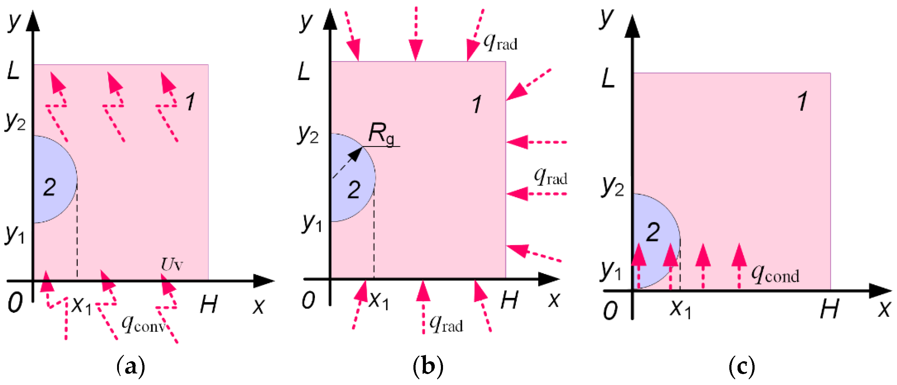
2.1. Physical Problem Statement

The ignition of a sphere-shaped double gas hydrate particle was investigated using three heat supply schemes: convective, radiant, and conductive. When stating the problem for convective heating, an air flow with a temperature that varied in the range of 973–1273 K was assumed to be supplied from below to the hydrate sample (methane-propane, particle radius Rg = 0.005 m), located in the geometric solution domain with the following coordinates (X-position = 10Rg; Y-position = 10Rg). An increase in the hydrate temperature occurred as a result of the heat transfer from the outside air, whose temperature was much higher than the initial sample temperature. When the particle temperature exceeded the equilibrium temperature (at a pressure of 1 bar), the gas hydrate dissociated into gas and ice at a constant dissociation rate with the subsequent release and ignition of methane. Heating was conducted at a constant air flow rate Uv of 1 m/s. The time interval from when the heating started until the ignition conditions were met was the ignition delay time τ.
When stating the problem for radiant heating, it was assumed that a spherical gas hydrate particle is introduced into a high-temperature air medium (973–1273 K). A gas hydrate particle is heated (primarily due to radiant heat supply), and its surface temperature reaches the equilibrium temperature of dissociation. This is followed by the formation of an ice melting front with a boundary moving to the center (deep layers) of the hydrate particle. When the vaporization conditions are met, the water film evaporates. When the temperatures in the vicinity of the gas hydrate and the concentrations of the mixture (fuel, water vapors and inert gas) components rise to levels sufficient for ignition, the gas hydrate is ignited. Preliminary research has shown that depending on the ambient temperature, these conditions can be achieved before the ice melting or water film formation.
When stating the problem for conductive heating, it was assumed that a spherical gas hydrate particle (Rg = 0.005 m) with an initial temperature of 203 K was placed on a metal cylinder surface heated to high temperatures. The volume percent of fuel (methane) in the gas hydrate is known. The near-surface layer of the fuel is heated. At certain temperatures, dissociation begins, with the hydrate breaking up into ice and methane. With a temperature rise, the ice that is the gas hydrate component starts melting. On reaching the vaporization conditions, water evaporates from the gas hydrate surface. When dissociation intensifies, methane and propane enter the area filled with inert gas. A gas-vapor mixture with a fuel and inert gas emerges in the close vicinity of the gas hydrate particle. When reaching the temperatures and component concentrations sufficient for ignition, the mixture ignites.
In accordance with the contemporary theory of condensed substance combustion, two simultaneously satisfied criteria used to estimate the ignition delay times were adopted: (1) the energy released as a result of a chemical reaction of the fuel oxidation (methane-propane) is greater than the heat transferred from the heating source and emerging gas-vapor mixture; and (2) the temperature of the mixture of gaseous components of the fuel in the oxidation reaction zone exceeds the initial temperature of the heating source [31].
Key assumptions: (1) the particle remained spherical with a constant size Rg despite melting, evaporation, and combustion; (2) the dependence of the thermophysical characteristics on temperature was not taken into account; and (3) the mass exchange processes in the gas hydrate pores were not taken into account. These assumptions do not place any significant restrictions on the problem statement generality and are true for fast processes. In the ignition of hydrates, heating until combustion start takes more time than that of the complete water evaporation and hydrate decomposition. Note that in the case of estimating the total dissociation time of a gas hydrate, the assumption of a constant radius and the neglect of heat transfer in the pores of the gas hydrate are unacceptable. Therefore, in order to develop a model for the ignition and combustion of gas hydrates, it is necessary to consider the decrease in the size of the sample due to the release of gas from the hydrate, evaporation, and melting, and the influence of the self-preservation process. It is important to consider the problem with the influence of the real shape (non-spherical) and the size of the gas hydrate with different configurations (porosity and irregularities). When simulating the combustion of a gas hydrate, the resulting flame has an asymmetric shape. In the future, it is important to solve the problem of ignition and the combustion of gas hydrate in a 3-D formulation.

2.2. Mathematical Model and Numerical Methods

The solution domain for the heat transfer problem when using convective heating is presented in Figure 1a. A system of transient partial differential equations such as in [31] was used to describe the interrelated processes of heat transfer in the “hydrate particle–external gas medium” system under the conditions of chemical reactions, exothermic, and endothermic phase transformations at 0 < τ < τd.
When solving the problem of modeling the process of gas hydrate ignition, the authors used the conjugation of the Cartesian and spherical systems. This approach is widely used in modeling. For a more detailed description of the basic pairing procedures, see [37].
For the mixture of water vapors, combustible gas, and air (0 < x < H, 0 < y < L):
Continuity equation
2 ψ x 2 + 2 ψ y 2 = ω ,   ω = v x u y
Equation of motion
ω t + u ω x + v ω y = γ ( 2 ω x 2 + 2 ω y 2 ) ,   u = ψ y ,   v = ψ x ,   ω = rot z v = v x u y
Energy equation
( T 1 t + u T 1 x + v T 1 y ) = a 1 ( 2 T 1 x 2 + 2 T 1 y 2 ) + i = 1 n Q i W i ,   W i = A r i T 1 β r i e E r i / R t T 1 ;
Hydrate gas (Cg) and water vapor (Cw) diffusion equation
ρ 1 ( C g t + u C g x + v C g y ) = ρ 1 D 1 ( 2 C g x 2 + 2 C g y 2 ) W i
ρ 1 ( C w t + u C w x + v C w y ) = ρ 1 D 1 ( 2 C w x 2 + 2 C w y 2 )
C w + C g + C o = 1
Energy equation for hydrate particles (0 < r < Rg, 0 < φ < 2π):
T 2 t = a 2 2 T 2 r 2 + 2 r T 2 r
The volume percentage of the gas-vapor mixture components was calculated from their mass concentrations using the equations:
η 11 = C g / ρ 11 C g / ρ 11 + C w / ρ 12 + C o / ρ 13 ,   η 12 = C w / ρ 12 C g / ρ 11 + C w / ρ 12 + C o / ρ 13 , η 11 + η 12 + η 13 = 1 .
The thermophysical characteristics of the gas-vapor mixture as a heterogeneous system were given by
λ 1 = λ 11 η 11 + λ 12 η 12 + λ 13 η 13 ,   C 1 = C 11 η 11 + C 12 η 12 + C 13 η 13 , ρ 1 = ρ 11 η 11 + ρ 12 η 12 + ρ 13 η 13
Initial conditions (t = 0): T = Tg0, Co = 1, Cg = 0, Cw = 0, ψ = 0, ω = 0 at 0 < x < H, 0 < y < L; T = Th0 at 0 < r < Rg, 0 < φ < 2π.
Boundary conditions at t > 0:
T = T g ,   C o = 1 ,   C g = 0 ,   C w = 0 ,   ψ y = U v ,   y = 0 ,   0 < x < H ;
2 T y 2 = 0 ,   2 C o y 2 = 0 ,   2 C g y 2 = 0 ,   2 C w y 2 = 0 ,   ψ y = 0 ,   y = L ,   0 < x < H ;
T x = 0 ,   C o = 0 ,   C g = 0 ,   C w = 0 ,   ψ x = 0 ,   at   x = 0 ,   0 < y < y 1 ;   y 2 < y < L ;   T x = 0 ,   x = 0 , y 1 < y < y 2 ;
2 T x 2 = 0 ,   2 C o x 2 = 0 ,   2 C g x 2 = 0 ,   2 C w x 2 = 0 ,   ψ x = 0 ,   x = H ,   0 < y < L .
The thermal effects of dissociation, melting, and vaporization at the hydrate particle–external gas medium interface were taken into account in the boundary conditions of the fourth kind:
R = R g ,   0 < φ < 2 π , λ 1 T 1 r Q e W e Q m W m Q g W g = λ 2 T 2 r ,   T 1 = T 2 ,   ρ 12 D 12 C w r = W ew ,   ρ 11 D 11 C 11 r = W g ,   2 C o r 2 = 0 .
The ice melting rate was calculated by the formula factoring in the linear velocity of the melting front (Vm) that corresponded to the movement of the front heating to the ice melting temperature (0 °C):
W m = V m ρ 12 .
The water evaporation rate was given by
W e = A ( P e n P e ) 2 π R T w / M w ,
where A is the accommodation coefficient; P e n is the equilibrium vapor pressure; Pe is the pressure of vapors over the surface; Mw is the molecular mass; Tw is the liquid surface temperature.
The solution domain for the heat transfer problem when using radiant heating is presented in Figure 1b [36]. The density of the heat flux supplied to the sample by using the radiant heat exchange is given by [38]
q r = σ ε T 2 4 .
The fundamental equations corresponded to the problem statement with convective heating. The thermal effects of dissociation, melting, and vaporization at the hydrate particl—external gas medium interface and the heat supply by radiation were taken into account in the conditions at the outer boundaries of the solution domain:
y = L ,   0   <   x   <   H ,   x = H ,   0   <   y   < L , λ 1 T 1 r = q r .
The solution domain for the heat transfer problem when using conductive heating is presented in Figure 1c [31]. The thermal effects of dissociation, melting, and vaporization at the particle—gas medium interface and the heat supply by conduction from the heated substrate were taken into account in the boundary condition:
y = 0 ,   0   <   x   <   H , λ 1 T 1 r = q cond .
The density of the heat flux supplied to the fuel sample by conduction is given by
q cond = λ sub T sub T 1 .
The rate of the gas hydrate particle dissociation can be calculated using the following equation [39,40]:
X H t = 6 k R B ρ H d 0 P eq P 0 1 + γ X H 2 / 3
where XH is the percentage of the remaining hydrate (hydrate conversion degree); kR is the kinetic coefficient of the dissociation rate; B is the initial content of gas in the hydrate; ρH is the density of hydrate particles; d0 is the average size of hydrate particles; Peq is the equilibrium pressure of gas over the hydrate; P0 is the partial gas pressure; γ is the coefficient representing the effect of pore resistance. Since ignition occurred within a short time, the fuel sample temperature did not change significantly. This is why modeling in a first approximation is possible with an assumption about the constant dissociation rate. Below are the modeling results at several gas dissociation rates ranging from the minimum to maximum at a corresponding pressure of the external gas medium.
To increase the solution accuracy, a time increment of 10−5 s was used. The adopted sizes of the solution domain (x = H, y = L) were ten-fold larger than the particle sizes (Rg = x1, D = y2y1. The problem was solved by the finite element method. The scheme of the problem solution area was with a physics-controlled mesh (8700 elements). The calculations were performed using a 4-core computer (processor 3.4 GHz Intel Core i5-3570 CPU, 32 GB, 64 K L1 cache, 1 MB L2 cache). The calculation time ranged from 2 to 20 min. The source data for modeling are presented in Table 1.

3. Results and Discussion

Gas hydrate combustion involves a certain group of processes, namely, dissociation, gas release, the formation of a water film on the hydrate surface, its evaporation, the diffusion of gas inside the hydrate, self-preservation, the formation of a gas-vapor mixture and its oxidation, and the release of additional energy in the gas phase, thus contributing to the heating of deep layers of the sample and burnout of the whole gas volume. A variety of factors affects the combustion behavior of methane hydrate. These include ambient temperature, the size and density of the pores within the hydrate, the characteristics of the oncoming oxidizer gas flow, the size and uniformity of the gas hydrates, their shape, phase transformations, etc. This research establishes the role of a group of factors when determining the key process characteristics (ignition delay times of gas hydrate). The adequacy of the developed model was preliminarily evaluated by comparing the calculated ignition delay times with known experimental data. Figure 2 presents the corresponding comparison results that demonstrate a satisfactory correlation between the experimental and modeling values. Taking the experimental data dispersion and assumptions made in the mathematical modeling into account, the resulting discrepancy between the experimental and theoretical ignition delay times can be considered as rather low. Therefore, the model can be considered as adequate.

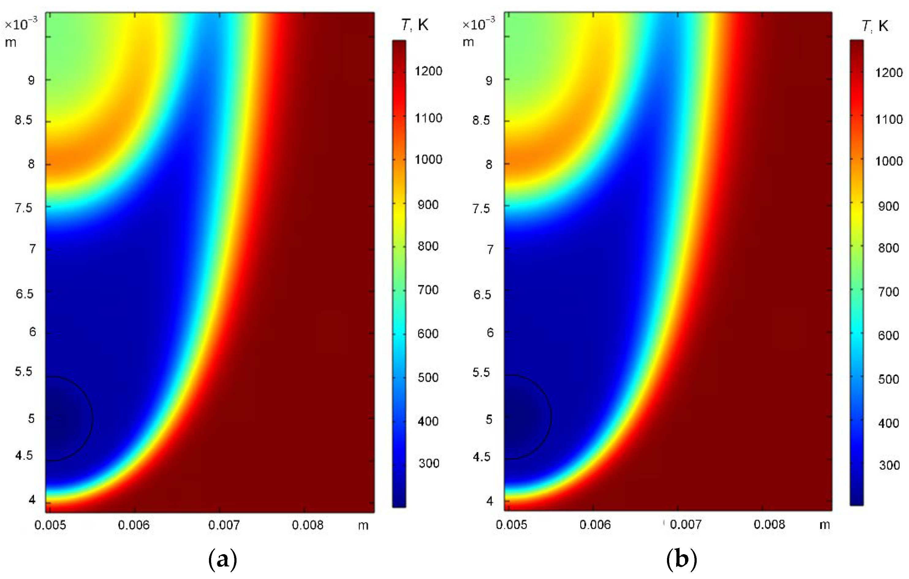
3.1. Effect of Heating Source Temperature

The conducted theoretical research provided the ignition delay times of a double gas hydrate particle when varying the heating source temperature and using different schemes of heat supply (radiant, convective, and conductive) to the sample (Figure 2a–c). The comparison of the ignition delay times of the gas hydrates obtained in this research showed a positive correlation between the experimental and previous theoretical data [31,36]. The lowest ignition delay times corresponded to the radiant heating conditions (up to 0.018 s (Figure 2a)) and decreased by 93% with an increase in the temperature in the muffle furnace in the range of 973–1273 K. Minimum delays during radiant heating can be explained by the fact that heat is evenly supplied to the gas hydrate from all sides. Under the conditions of convective and conductive heating, the essential heat flux is supplied from one side of the particle. The internal layers are heated more slowly as it takes more time for the gas hydrate pores to open for the gas release and subsequent ignition of the gas-vapor mixture compared with the radiant heating scheme. The highest ignition delay times were established when using convective heating, they did not exceed 0.1 s at 973 K (Figure 2b). With a rise in temperature, the ignition delay times also decreased to 0.004 s (by 96%). For conductive heating, the ignition delay times decreased from 0.045 s to 0.0005 s with an increase in the metal heater temperature (Figure 2c). The Arrhenius law was found to be crucial for the reaction rates in all three heating schemes. As seen in Figure 2a–c, the heating source temperatures exponentially affected the ignition delay times.
Table 2 presents the ignition delay times established for a methane-propane hydrate particle exposed to radiant heating at a variable furnace temperature. There were also ignition delay times of methane, propane, and ethane with the kinetics corresponding to the reactions of these gases in the air in the form of a gas-vapor mixture. These gases were chosen for comparison as the most common components in the composition of natural and artificial hydrates. The chemical reaction constants for the theoretical calculation of the ignition delay times under the conditions of radiant heating (Ea—activation energy, k0—pre-exponential factor) for methane, propane, and ethane, adopted for the temperature range of 1000–3000 K [41] (Table 2), were taken from [42,43,44].
Considerable differences in the ignition delay times of the gas hydrate particles and gases (methane, propane) were attributed to the significantly different macrokinetics (Table 2). These differences arise from the fact that these kinetics are conventionally defined for different heating conditions. In the case of gas hydrates, the heating conditions have a major role to play. Therefore, it is important to adjust the kinetic scheme to the process conditions. The gas hydrate is not pure methane and propane. It consists of gases with certain impurities. Thus, the macrokinetics of the oxidation reactions needs to be adjusted relative to the reference values when scaling to the actual conditions of the sample ignition. A substantial volume in the composition of granules belongs to water in the form of ice, which turns to vapor when heated. The vapor, in turn, has a significant effect on the physical and chemical processes during the ignition and combustion of gas hydrate. As a result, the ignition delay times increase several-fold compared to the ignition of methane and propane as gas mixtures in the air medium (Table 2). The combustion of methane, propane, and ethane proceeds in a one-stage reaction:
CH4 + 2O2→CO2 + 2H2O,
C3H8 + 5O2→3CO2 + 4H2O,
2C2H6 + 7O2→4CO2 + 6H2O.
The combustion of methane-propane hydrate (C3H8·2CH4·17H2O), in turn, yields multi-stage chemical reactions due to its multicomponent composition and complex combustion involving several stages (gas dissociation, ice melting, water evaporation).

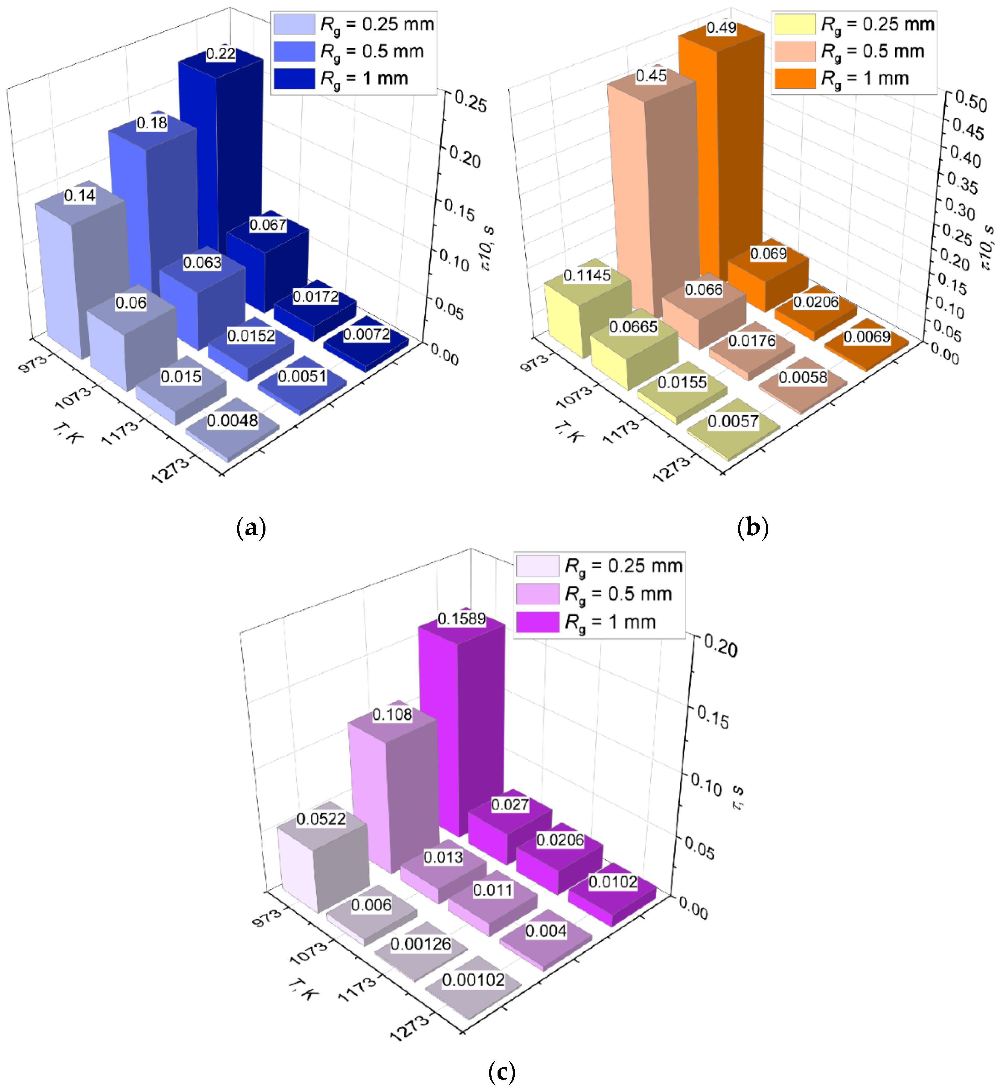
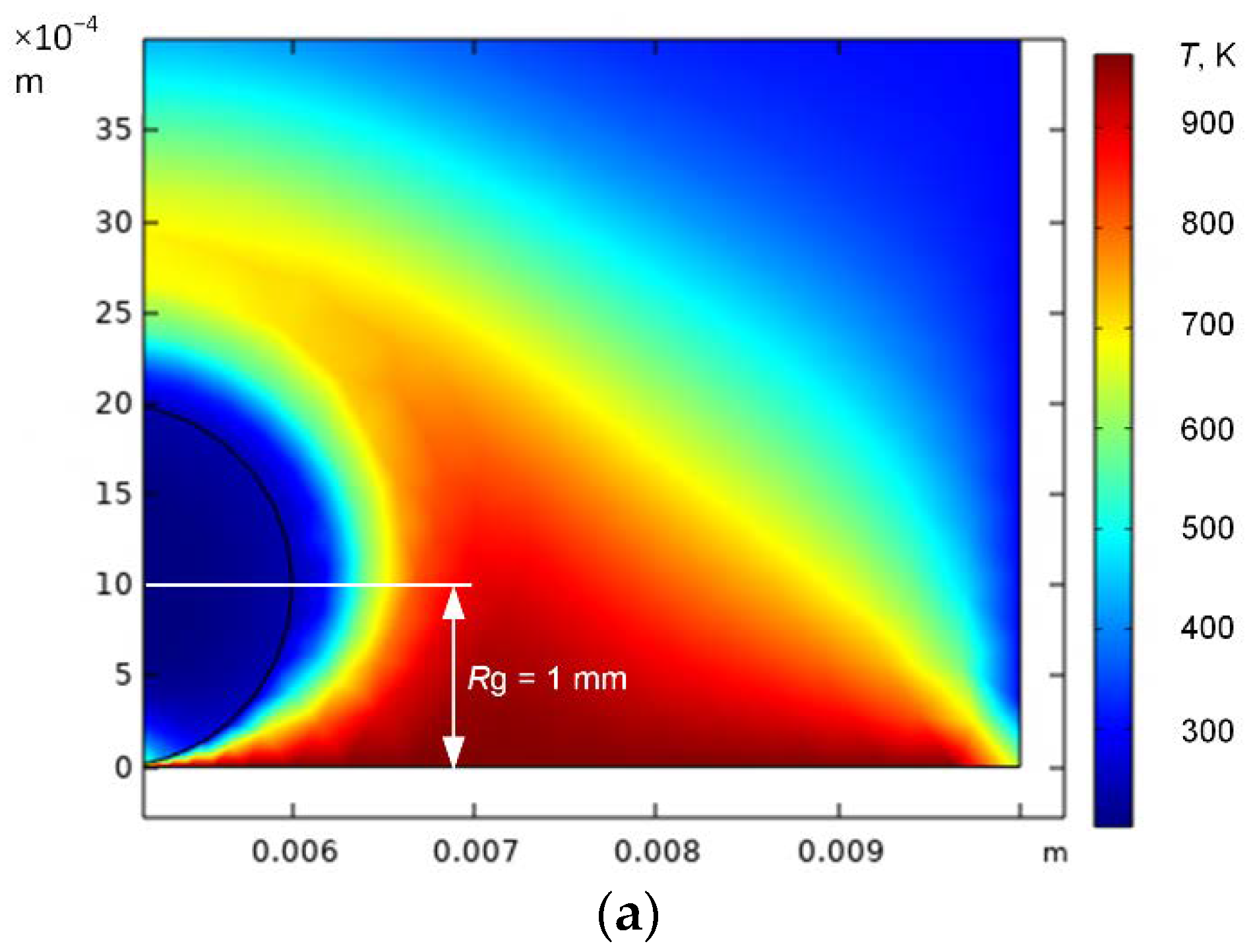
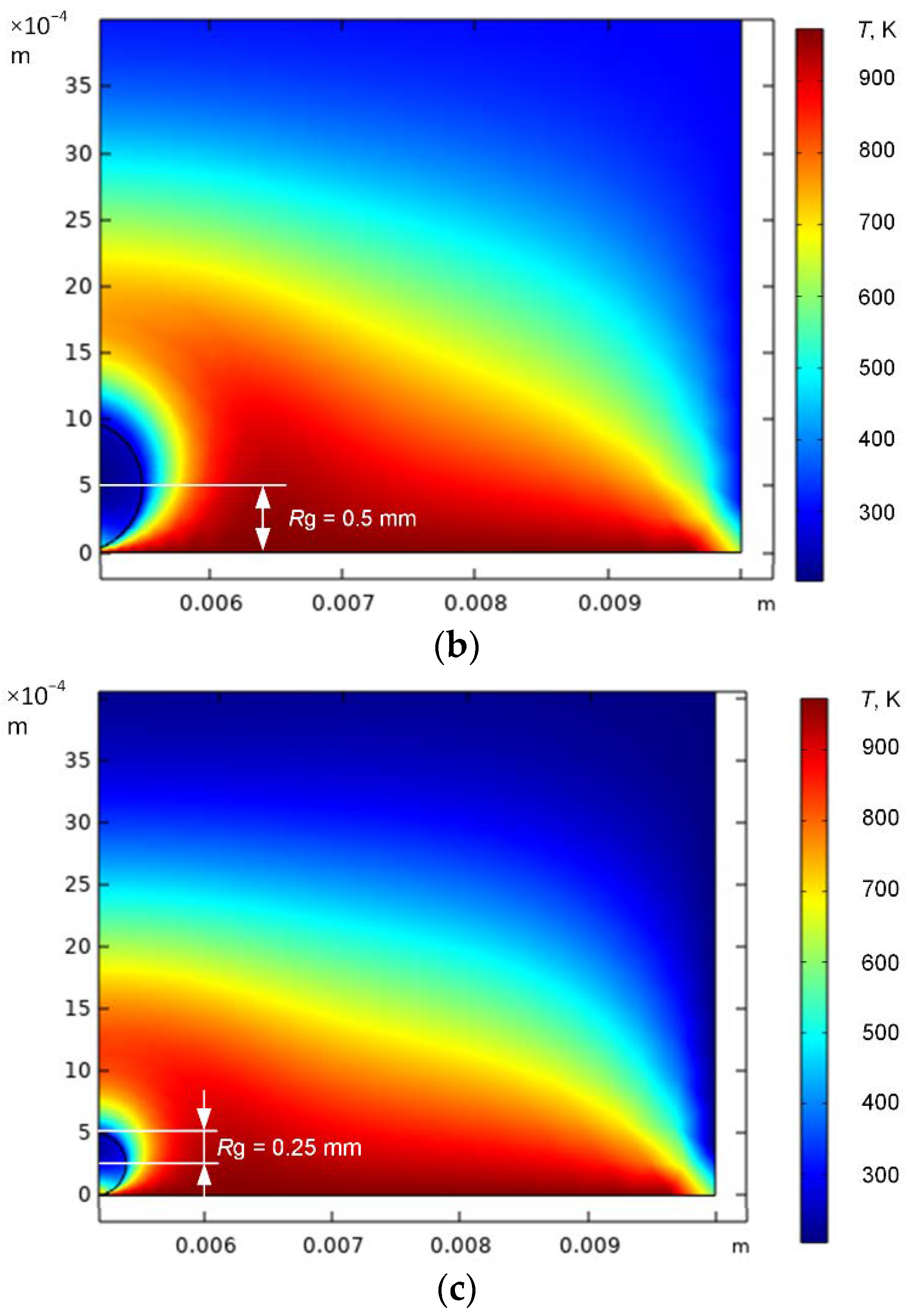
3.2. Effect of Hydrate Particle Size

The research findings on the oxidation of the gas hydrate samples [23,24] indicate that the size of the particle significantly affects its combustion conditions. For storage and transportation, solid gas hydrates or pressed hydrates of a large diameter should be used. For solid particles, the dissociation rate is inversely proportional to the particle radius. For pressed particles, a decrease in porosity and increase in the sphere radius increases the filtration resistance and, in contrast, reduces the dissociation rate. In the combustion of large spheres, other factors are responsible for improving the efficiency of gas hydrate burnout. For pressed spheres (low porosity), almost all of the water trickles down, and the concentration of water vapors in the combustion area decreases several-fold, which significantly increases the combustion temperature. With highly porous spheres, water enters the ice frame and participates in evaporation, which leads to a higher vapor content in the combustion area and decreases the flame temperature. Pressing (reduction in the sphere porosity) increases the filtration resistance and decreases the heating rate. Lower porosity reduces the temperature conductivity of the sphere. Thus, a change in the sphere size and porosity results in the competing effect of a group of factors. Among them, the vapor content in the flame area has a decisive effect. The other factors (filtration resistance and temperature conductivity) are less significant due to a high heat flux and high dissociation rate during combustion. Therefore, it is important to consider the influence of the gas hydrate sample radius on the main characteristics of combustion start. It was established [45] that the average size of the artificial gas hydrate particles for efficient storage and usage is 0.8–1 mm. In this research, the range of 0.25–1 mm was chosen for Rg. The ignition delay times for all of the heating schemes (Figure 3a–c) indicated that an increase in the gas hydrate particle diameter led to significantly higher ignition delay times, which is related to the dissociation rate. A greater diameter of the particle increases the filtration resistance for the gas flow in the open pores [45]. Consequently, the maximum dissociation rate is achieved for the smallest particles. The minimum concentration required for the fuel to ignite is achieved faster for a small particle than for a larger one. This is conditioned by the contribution of the decisive factors. A larger-sized hydrate particle is characterized by a great amount of water that is accumulated in the hydrate during melting, which prevents the heat transfer from the heating source to the hydrate and increases the diffusion resistance of the gaseous methane-propane.
Under the conditions of radiant heating (Figure 3a), a four-fold increase in the hydrate particle radius increased the ignition delay times by 35% on average at a heating source temperature of 973–1273 K. When a gas hydrate was conductively heated (Figure 3b) at relatively low heating source temperatures (973 K), a change in the particle radius from 0.25 mm to 1 mm increased the ignition delay times by 77% (from 0.01145 s to 0.049 s). At high heating source temperatures (over 1173 K), the ignition delay times grew by 20% with an increase in the radius when conductive heating was used (Figure 3b). Thus, during conductive heating under high-temperature conditions, the gas hydrate ignites approximately with the same delay irrespective of its radius. Under the conditions of convective heating, the opposite is the case: at T = 973 K, the ignition delay times increase by 68% when the radius Rg changes in the range of 0.25–1 mm. At a heating source temperature of 1273 K, τ decreases by 90% (Figure 3c). Such a difference from the conductive heating scheme has the following explanation. When there is convection, the heating of a particle from the external gas is determined by the Nusselt number (Nu), which is proportional to the square root of the Reynolds number (Re) in the laminar gas flow (i.e., the convective heat transfer coefficient for the gas phase α~1/(R0)0.5), where R0 is the particle radius. With a decrease in the radius, the heat flux from the gas to the particle increases, as does the heating and dissociation rates. Thus, the heat flux for a particle with R0 = 0.25 mm will be twice as high (R0 decreases four times) when compared to a particle with R0 = 1 mm. As above-mentioned, the growth of the dissociation rate leads to lower ignition delay times. Thus, when there is convection, two factors contribute to a significantly lower ignition delay time. The heat exchange coefficient is inversely proportional to the radius (1/R0) and is related to convection in the form (~1/(R0)0.5). The total effect gives ~1/(R0)1.5. This is accounted for by the fact that under the conditions of convective heating at high temperatures, the gas hydrate pores open faster for gas release. The larger the gas hydrate particle radius, the more pores are formed on the hydrate surface. In turn, the heat flux supplied from below to the gas hydrate with a larger radius blows off the water layer resulting from the melting of ice to the open pores, thus preventing the gas release, which leads to higher ignition delay times. The growth of the particle diameter increases the thickness of the water film. This decreases the gas flow (growth of the gas resistance through the water film) and increases the water flow to the combustion zone, which reduces the reaction rate in the flame region.
The hydrate sample with Rg = 0.25 mm was characterized by a low content of gas, which led to a low combustion rate and lower heat transfer to the hydrate particle (Figure 4a–c). Figure 4a clearly shows great temperature fluctuations in closer proximity to the hydrate sample than they were in Figure 4b,c, where the gas hydrate particles of larger typical sizes are presented.

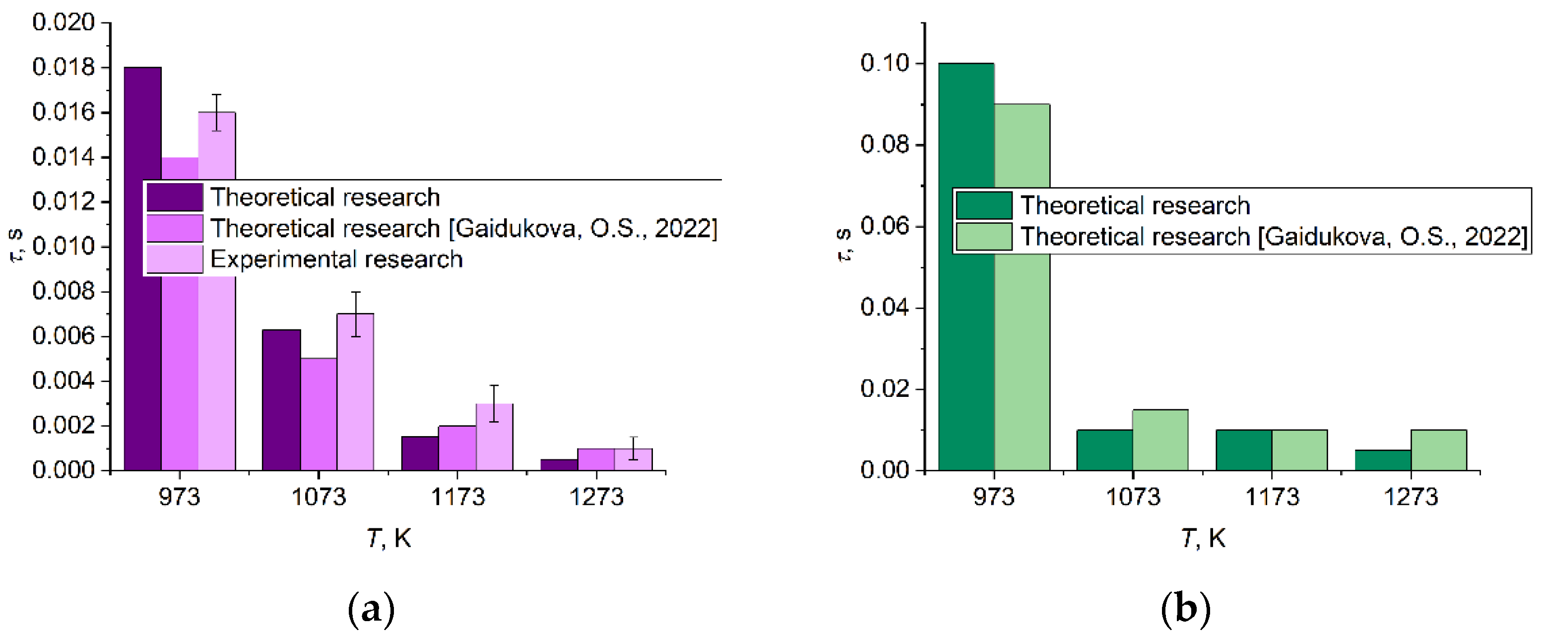
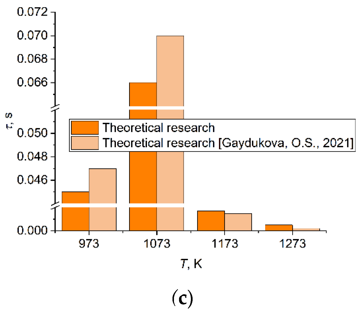
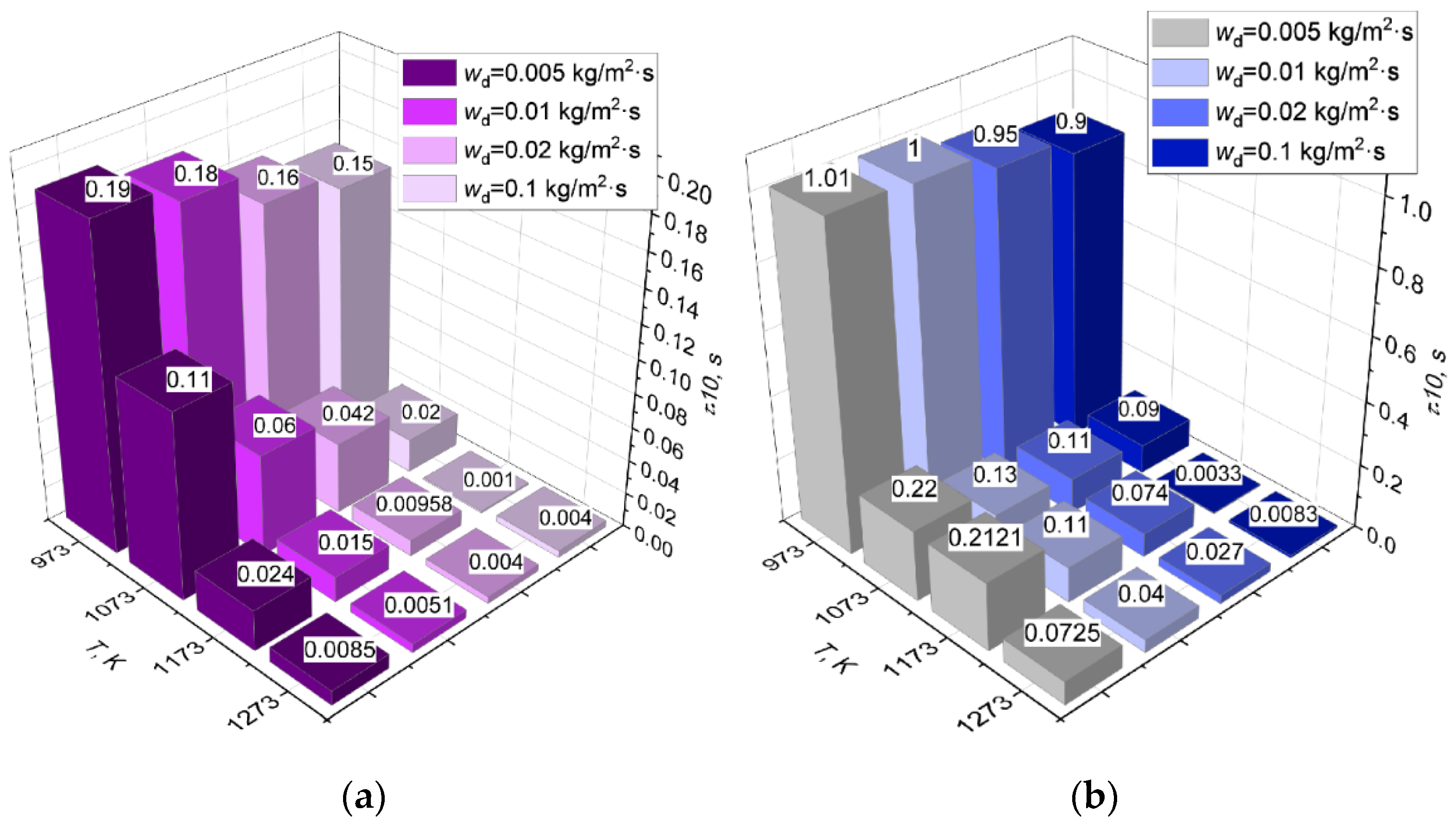
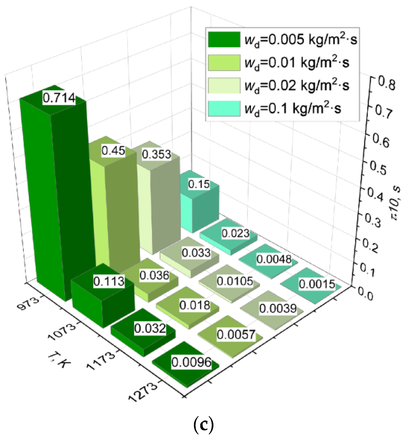
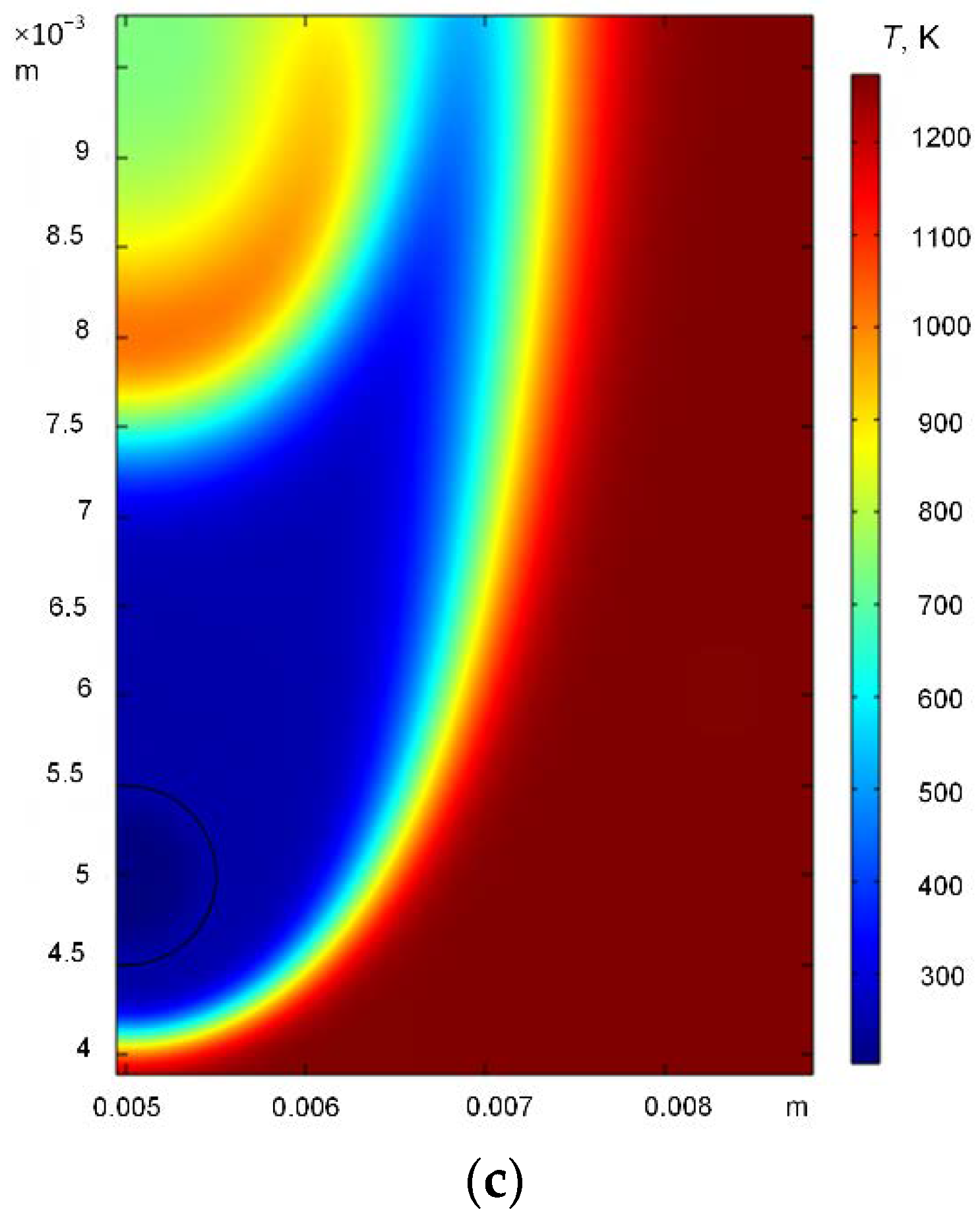
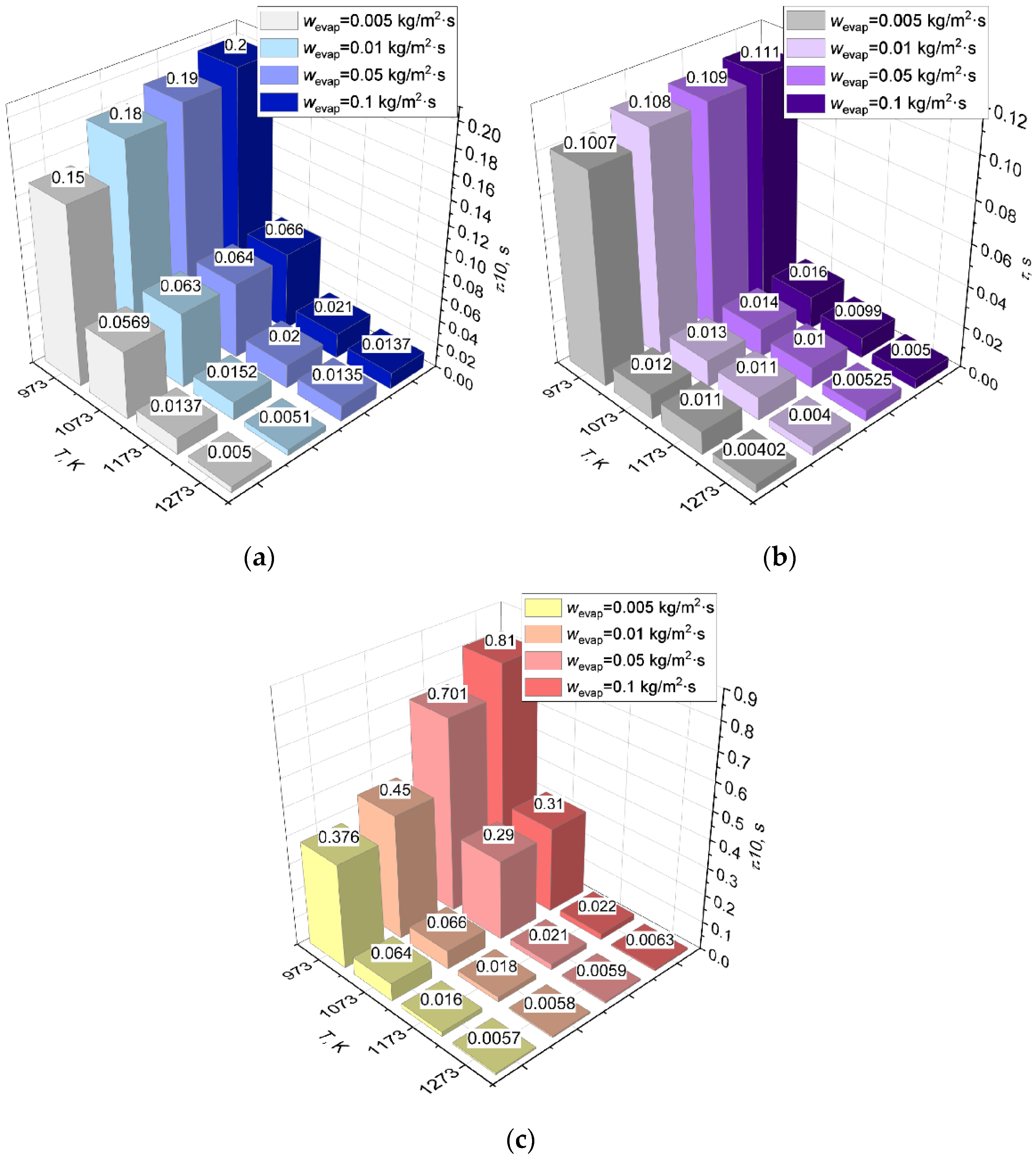
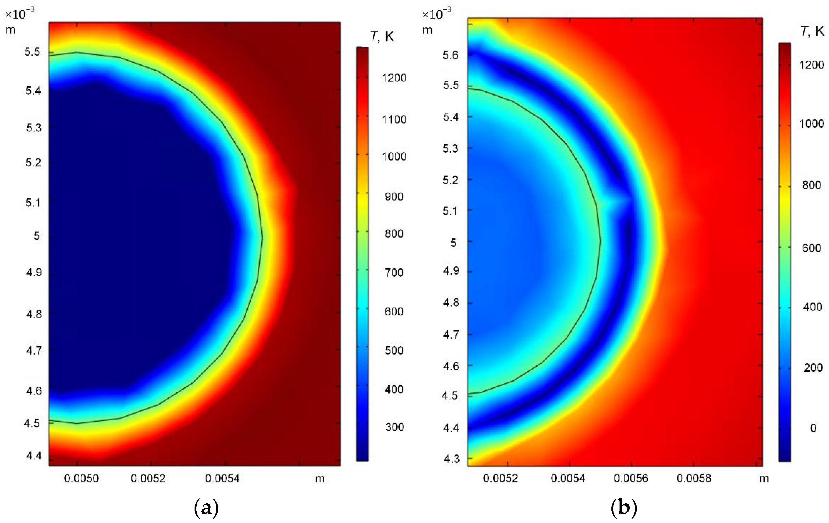
3.3. Effect of Dissociation and Evaporation Rates

Gas hydrate combustion includes a variety of interrelated processes: dissociation, ice melting, water evaporation, gas release, and oxidation reactions. Hydrate dissociation [45,46,47] and water evaporation from the particle surface [1,48] are contributing factors to the ignition delay. Gas hydrate dissociation is a complicated process. The main characteristic of dissociation is its rate, which depends on numerous factors:
W d = c g ρ g 2 π R d ,
c g = 2 K g B g ,   K g = 3 k R P eq P gas b ρ g 2 R d ,   k R = K 0 d exp E a R T g ,   P eq = exp 15.517 2105.16 / T g 1000 ,  
b = 0.12 methane   concentration ,   B g = R d k R μ g k F ρ g ,   k F = P 3 S p 3 F 1 P 2 ,   S p = π R p 2 ,
where P is the porosity; F is the shape coefficient for sphere (150); Rp is the pore radius (0.5 µm).
The dissociation rate is affected by the pore density, the size of the gas hydrate particles, ambient temperature and pressure, the density of the heat flux supplied, and the type of the gas hydrate unit cell. The dissociation rate changes depending on the type of heat flux supplied to the gas hydrate particle, the heating source temperature, and heating conditions [48]. An increase in the heat flux density increases the dissociation rate of methane hydrate by almost one order of magnitude. At low heating temperatures, the density of the pore distribution in the gas hydrate decreases, which significantly changes the breakup rate during dissociation [49,50]. A continuous increase in the heating source temperature leads to a steadily increasing dissociation rate of the hydrate inside the spherical particle, which enhances the combustion intensity of the flame [1]. Depending on the heating conditions and the type of gas hydrate, the dissociation rate changes in a wide range. In this research, the known mass dissociation rate wd was chosen in the range of 0.005–0.1 kg/m2·s, which corresponded most closely to gas hydrate combustion. Figure 5a–c presents the ignition delay times determined for the gas hydrate when varying the mass dissociation rate and heating source temperature using radiant, convective, and conductive schemes. In every heating scheme, there was a decrease in the ignition delay times with the growth in the mass dissociation rate. Under the conditions of radiant heating, the gas hydrate ignition delay times decreased by 22–53% when the mass dissociation rate changed in the range of 0.005–0.1 kg/m2·s and the heating source temperature increased from 973 K to 1273 K, respectively (Figure 5a). When supplying convective heat to the gas hydrate particle and varying the mass dissociation rate and temperature in the same way, the ignition delay times decreased by 11–89%, respectively (Figure 5b). During conductive heating, the ignition delay times decreased most dramatically by 79% to 89% when the mass dissociation rate increased from 0.005 kg/m2·s to 0.1 kg/m2·s (Figure 5c). It is clear in Figure 5a–c that at higher heating source temperatures, the mass dissociation rate changed the ignition delay times more significantly. The probability of autoignition of the gas hydrate increased with a rise in the dissociation rate and gas temperature. At 973 K, the ignition delay times changed little (by up to 20% during radiant and convective heating) (Figure 5a,b). Under the conditions of the conductive heating of a gas hydrate particle, at a high dissociation rate (0.1 kg/m2·s), the sample was heated from below when it was in close contact with the heated metal cylinder. Above the particle, an ice crust developed and then melted, while below it, gas was released from the pores, enhancing the ignition of the gas-vapor mixture. This can explain a sharp reduction in the ignition delay times (by up to 85%) with an increase in the mass dissociation rate in Figure 5c.
Figure 6a–c presents the temperature fields in the gas hydrate ignition area when using convective heating and varying the mass dissociation rate for a heating source temperature of 1273 K. Significantly, the temperature traces were distributed identically around the gas hydrate particle with Rg = 0.5 mm, irrespective of the dissociation rate.
The ice in the gas hydrate composition melts to produce water. Liquid evaporation has a decisive effect on the characteristics of gas hydrate ignition and combustion at relatively low temperatures [1]. The water vapors were found [1] to significantly change the development of some elementary reactions (chemical effect), which led to a lower flame temperature. The vapor resulting from the water evaporation also reduces the combustion rate [1]. The evaporation rate of water generated on the gas hydrate surface is unstable as it is conditioned by dissociation, which, in turn, occurs at different rates depending on the different factors and conditions described above. The water evaporation rate affects the release of gas from the hydrate pores and the self-preservation phenomenon that suppresses the gas release. The more slowly the water evaporates from the surface, the higher the risk of the formation of an ice crust under certain conditions. The ice crust clogs the channels emerging from the pores for combustible gas release. Therefore, the rate of water evaporation from the gas hydrate surface is the key factor in the kinetics of hydrate combustion that should be taken into account and analyzed. Figure 7a–c presents the gas hydrate ignition delay times when varying the mass evaporation rate of water and the heating source temperature using radiant, convective, and conductive heating schemes. It is clear from Figure 7 that the ignition delay times changed steadily with the growth in the mass rate of water evaporation from the hydrate particle surface. At a heating source temperature of 1273 K, the ignition delay times for all of the heating schemes (radiant, convective, and conductive) increased by 63%, 23%, and 4%, respectively, with an increase in the mass evaporation rate of water from 0.005 kg/m2·s to 0.05 kg/m2·s. At T = 1273 K, a rise in the mass evaporation rate to 0.1 kg/m2·s increased the ignition delay times by 15%, on average, when convective and conductive heating were applied (Figure 7b,c). Under the conditions of radiant heating, at the same heating source temperature and evaporation rate, the ignition delay times increased almost three-fold (Figure 7a). Under the conditions of conductive heating, the ignition delay times increased with a rise in the mass evaporation rate of water by 10–80% (Figure 7c). Such changes in the ignition delay times can be explained by the following. When the dissociation rate reaches its peak, the ice on the gas hydrate particle surface quickly melts and water evaporation becomes more rapid. With an increase in the heating source temperature, the water film on the particle surface builds up and becomes thicker, thus preventing the release of gas from the hydrate. When gas passes through a thick water film, small methane-propane bubbles appear. The bubble then collapses to release gas, which leads to a local flame. The condensation of water that has not yet evaporated and trickles down the hydrate particle leads to local extinction. Thus, a range of factors, in addition to the water evaporation rate, contributes to the ignition delay times at this stage: the thickness of the newly-formed water film, the dissociation rate, and the amount of condensed water.
Figure 8a,b presents the temperature fields in the gas hydrate ignition area under the conditions of radiant heating at a mass rate of water evaporation from the gas hydrate sample surface wevap = 0.01 kg/m2·s and 0.1 kg/m2·s at a heating source temperature of 1273 K. It is clear from Figure 8a,b that the higher the rate of water evaporation from the hydrate particle surface (Figure 8b), the more the gas hydrate particles and the area around it are cooled due to the water vapor generation. In contrast, at a lower evaporation rate of water (Figure 8a), the temperatures around the gas hydrate particle were higher.

4. Conclusions

Using the developed mathematical model, theoretical research into the characteristics of a double gas hydrate particle ignition was conducted when varying the parameters affecting the combustion patterns, namely, the ambient temperature, heating scheme, particle size, and phase transformation rates. It was established that at an ambient temperature of 973–1273 K, the lowest ignition delay times corresponded to radiant heating (up to 0.018 s), whereas the maximum ones to convective heating (up to 0.01 s). A rise in the mass dissociation rate when using radiant, convective, and conductive heating schemes brought about a 80–90% decrease in the ignition delay times. For all of the heating schemes, the ignition delay times of the methane-propane hydrate increased by 90% with an increase in the hydrate particle diameter. The gas hydrate ignition delay times changed unsteadily with the growth in the mass rate of water evaporation from the hydrate particle surface. In the conducted research, the temperature limits of these regimes were established when using single and double gas hydrates.

Author Contributions

Conceptualization, P.S.; Data curation, P.S.; Funding acquisition, P.S.; Investigation, S.M., D.R. and O.G.; Writing—original draft, P.S., S.M. and O.G.; Writing—review and editing, P.S., S.M. and O.G. All authors have read and agreed to the published version of the manuscript.

Funding

The research was supported by a program of the National Research Tomsk Polytechnic University (Priority-2030-NIP/EB-006-0000-2022).

Conflicts of Interest

The authors declare no conflict of interest.

References

  1. Cui, G.; Dong, Z.; Wang, S.; Xing, X.; Shan, T.; Li, Z. Effect of the water on the flame characteristics of methane hydrate combustion. Appl. Energy 2020, 259, 114205. [Google Scholar] [CrossRef]
  2. Hečko, D.; Malcho, M.; Mičko, P.; Kantová, N.Č.; Kolková, Z.; Hrabovský, P.; Belány, P. Controlled production of natural gas hydrates in an experimental device with an internal circulation circuit. Appl. Sci. 2022, 12, 312. [Google Scholar] [CrossRef]
  3. Lee, T.; Lee, J.Y.; Ahn, T.; Son, H.A. Numerical Simulation of Gas Hydrate Production Using the Cyclic Depressurization Method in the Ulleung Basin of the Korea East Sea. Appl. Sci. 2021, 11, 9748. [Google Scholar] [CrossRef]
  4. Liu, Y.; Hou, J.; Chen, Z.; Bai, Y.; Su, H.; Zhao, E.; Li, G. Enhancing hot water flooding in hydrate bearing layers through a novel staged production method. Energy 2021, 217, 119319. [Google Scholar] [CrossRef]
  5. Chen, H.; Han, B.; Lang, C.; Wen, M.; Fan, B.; Liu, Z. Hydrates for cold storage: Formation characteristics, stability, and promoters. Appl. Sci. 2021, 11, 10470. [Google Scholar] [CrossRef]
  6. Luketa, A.; Blanchat, T. The phoenix series large-scale methane gas burner experiments and liquid methane pool fires experiments on water. Combust. Flame 2015, 162, 4497–4513. [Google Scholar] [CrossRef]
  7. Misyura, S.Y.; Manakov, A.Y.; Nyashina, G.S.; Gaidukova, O.S.; Morozov, V.S.; Skiba, S.S. Gas hydrate combustion in five method of combustion organization. Entropy 2020, 22, 710. [Google Scholar] [CrossRef]
  8. Chien, Y.C.; Dunn-Rankin, D. Combustion characteristics of methane hydrate flames. Energies 2019, 12, 1939. [Google Scholar] [CrossRef]
  9. Wu, F.-H.; Chao, Y.-C. A Study of Methane Hydrate Combustion Phenomenon Using a Cylindrical Porous Burner. Combust. Sci. Technol. 2016, 188, 1983–2002. [Google Scholar] [CrossRef]
  10. Maruyama, Y.; Fuse, M.J.; Yokomori, T.; Ohmura, R.; Watanabe, S.; Iwasaki, T.; Iwabuchi, W.; Ueda, T. Experimental investigation of flame spreading over pure methane hydrate in a laminar boundary layer. Proc. Combust. Inst. 2013, 34, 2131–2138. [Google Scholar] [CrossRef]
  11. Yoshioka, T.; Yamamoto, Y.; Yokomori, T.; Ohmura, R.; Ueda, T. Experimental study on combustion of a methane hydrate sphere. Exp. Fluids 2015, 56, 192. [Google Scholar] [CrossRef]
  12. Rossi, F.; Gambelli, A.M.; Sharma, D.K.; Castellani, B.; Nicolini, A.; Castaldi, M.J. Experiments on methane hydrates formation in seabed deposits and gas recovery adopting carbon dioxide replacement strategies. Appl. Therm. Eng. 2019, 148, 371–381. [Google Scholar] [CrossRef]
  13. Misyura, S.Y. Comparing the dissociation kinetics of various gas hydrates during combustion: Assessment of key factors to improve combustion efficiency. Appl. Energy 2020, 270, 115042. [Google Scholar] [CrossRef]
  14. Chen, B.; Sun, H.; Zhao, G.; Wang, B.; Zhao, Y.; Yang, M. Experimental observation of methane hydrate dissociation via different depressurization modes under water phase flow. Fuel 2021, 283, 118908. [Google Scholar] [CrossRef]
  15. Ji, J.; Lin, S.; Zhao, C.; Li, K.; Gao, Z. Experimental study on initial temperature influence on flame spread characteristics of diesel and gasoline-diesel blends. Fuel 2016, 178, 283–289. [Google Scholar] [CrossRef]
  16. Lv, X.; Shi, B.; Zhou, S.; Wang, S.; Huang, W.; Sun, X. Study on the decomposition mechanism of natural gas hydrate particles and its microscopic agglomeration characteristics. Appl. Sci. 2018, 8, 2464. [Google Scholar] [CrossRef]
  17. Sahith, S.J.K.; Pedapati, S.R.; Lal, B. Investigation on gas hydrates formation and dissociation in multiphase gas dominant transmission pipelines. Appl. Sci. 2020, 10, 5052. [Google Scholar] [CrossRef]
  18. Lee, S.; Padilla, R.; Dunn-Rankin, D.; Pham, T.; Kwon, O.C. Extinction limits and structure of counterflow nonpremixed H2O-laden CH4/air flames. Energy 2015, 93, 442–450. [Google Scholar] [CrossRef]
  19. Chen, X.R.; Li, X.S.; Chen, Z.Y.; Zhang, Y.; Yan, K.F.; Lv, Q.N. Experimental investigation into the combustion characteristics of propane hydrates in porous media. Energies 2015, 8, 1242–1255. [Google Scholar] [CrossRef]
  20. Padilla, R.E.; Escofet-Martin, D.; Pham, T.; Pitz, W.J.; Dunn-Rankin, D. Structure and behavior of water-laden CH4/air counterflow diffusion flames. Combust. Flame 2018, 196, 439–451. [Google Scholar] [CrossRef]
  21. Jordà Juanós, A.; Sirignano, W.A. Pressure effects on real-gas laminar counterflow. Combust. Flame 2017, 181, 54–70. [Google Scholar] [CrossRef]
  22. Bar-Kohany, T.; Sirignano, W.A. Transient combustion of a methane-hydrate sphere. Combust. Flame 2016, 163, 284–300. [Google Scholar] [CrossRef]
  23. Cui, G.; Wang, S.; Dong, Z.; Xing, X.; Shan, T.; Li, Z. Effects of the diameter and the initial center temperature on the combustion characteristics of methane hydrate spheres. Appl. Energy 2020, 257, 114058. [Google Scholar] [CrossRef]
  24. Wang, S.; Cui, G.; Bi, H.; Liu, C.; Dong, Z.; Xing, X.; Li, Z.; Liu, J. Effect analysis on flame characteristics in the combustion of methane hydrate spheres under natural convective flow conditions. J. Nat. Gas Sci. Eng. 2020, 83, 103578. [Google Scholar] [CrossRef]
  25. Cui, G.; Dong, Z.; Xie, K.; Wang, S.; Guo, T.; Liu, J.; Xing, X.; Li, Z. Experimental study on the effect of airflow conditions on the combustion characteristics of methane hydrate. Fuel 2021, 300, 120926. [Google Scholar] [CrossRef]
  26. Gao, J.; Hossain, A.; Nakamura, Y. Flame base structures of micro-jet hydrogen/methane diffusion flames. Proc. Combust. Inst. 2017, 36, 4209–4216. [Google Scholar] [CrossRef]
  27. Wu, F.H.; Padilla, R.E.; Dunn-Rankin, D.; Chen, G.B.; Chao, Y.C. Thermal structure of methane hydrate fueled flames. Proc. Combust. Inst. 2017, 36, 4391–4398. [Google Scholar] [CrossRef]
  28. Sizikov, A.A.; Vlasov, V.A.; Stoporev, A.S.; Manakov, A.Y. Decomposition Kinetics and Self-Preservation of Methane Hydrate Particles in Crude Oil Dispersions: Experiments and Theory. Energy Fuels 2019, 33, 12353–12365. [Google Scholar] [CrossRef]
  29. Dagan, Y.; Bar-Kohany, T. Flame propagation through three-phase methane-hydrate particles. Combust. Flame 2018, 193, 25–35. [Google Scholar] [CrossRef]
  30. Chiglintseva, A.S.; Gimaltdinov, I.K.; Bayanov, I.M.; Stolpovsky, M.V. Modeling of the combustion process of methane hydrate taking into account the kinetics of the decomposition process. J. Phys. Conf. Ser. 2021, 2094, 022053. [Google Scholar] [CrossRef]
  31. Gaydukova, O.S.; Misyura, S.Y.; Strizhak, P.A. Investigating regularities of gas hydrate ignition on a heated surface: Experiments and modelling. Combust. Flame 2021, 228, 78–88. [Google Scholar] [CrossRef]
  32. Cui, G.; Dong, Z.; Xie, K.; Wang, S.; Guo, T.; Liu, J.; Xing, X.; Li, Z. Effects of gas content and ambient temperature on combustion characteristics of methane hydrate spheres. J. Nat. Gas Sci. Eng. 2021, 88, 103842. [Google Scholar] [CrossRef]
  33. Veluswamy, H.P.; Kumar, A.; Kumar, R.; Linga, P. An innovative approach to enhance methane hydrate formation kinetics with leucine for energy storage application. Appl. Energy 2017, 188, 190–199. [Google Scholar] [CrossRef]
  34. Sloan, E.D., Jr.; Koh, C.A.; Koh, C.A. Clathrate Hydrates of Natural Gases; CRC Press: Boca Raton, FL, USA, 2007. [Google Scholar] [CrossRef]
  35. Holder, G.D.; Hand, J.H. Multiple-phase equilibria in hydrates from methane, ethane, propane and water mixtures. AIChE J. 1982, 28, 440–447. [Google Scholar] [CrossRef]
  36. Gaidukova, O.S.; Misyura, S.Y.; Strizhak, P.A. Study of the gas hydrates ignition under heating different schemes. J. Eng. Phys. Thermophys. 2022, in press. [Google Scholar]
  37. Kuznetsov, G.V.; Strizhak, P.A. Heat and mass transfer at ignition of liquid fuel droplets spreading over the surface of massive hot bodies. J. Eng. Thermophys. 2010, 19, 75–84. [Google Scholar] [CrossRef]
  38. Kutateladze, S.S.; Leont’ev, A.I. Heat Transfer, Mass Transfer, and Friction in Turbulent Boundary Layers; Hemisphere: New York, NY, USA, 1989. [Google Scholar]
  39. Misyura, S.Y.; Donskoy, I.G.; Manakov, A.Y.; Morozov, V.S.; Strizhak, P.A.; Skiba, S.S.; Sagidullin, A.K. Studying the influence of key parameters on the methane hydrate dissociation in order to improve the storage efficiency. J. Energy Storage 2021, 44, 103288. [Google Scholar] [CrossRef]
  40. Misyura, S.Y.; Donskoy, I.G. Dissociation of a powder layer of methane gas hydrate in a wide range of temperatures and heat fluxes. Powder Technol. 2022, 397, 117017. [Google Scholar] [CrossRef]
  41. Frenklach, M.; Bornside, D.E. Shock-initiated ignition in methane-propane mixtures. Combust. Flame 1984, 56, 1–27. [Google Scholar] [CrossRef]
  42. Pomerantsev, V.V.; Arefyev, M.K.; Akhmedov, D.B. Fundamentals of Practical Combustion; Energoatom: Leningrad, Russia, 1986. [Google Scholar]
  43. Schädel, B.T.; Duisberg, M.; Deutschmann, O. Steam reforming of methane, ethane, propane, butane, and natural gas over a rhodium-based catalyst. Catal. Today 2009, 142, 42–51. [Google Scholar] [CrossRef]
  44. Grabowski, R.; Słoczyński, J. Kinetics of oxidative dehydrogenation of propane and ethane on VO x/SiO2 pure and with potassium additive. Chem. Eng. Process. Process Intensif. 2005, 44, 1082–1093. [Google Scholar] [CrossRef]
  45. Misyura, S.Y.; Donskoy, I.G. Dissociation of gas hydrate for a single particle and for a thick layer of particles: The effect of self-preservation on the dissociation kinetics of the gas hydrate layer. Fuel 2022, 314, 122759. [Google Scholar] [CrossRef]
  46. Chen, Z.; Li, D.; Zhang, S.; Liao, X.; Zhou, B.; Chen, D. A well-test model for gas hydrate dissociation considering a dynamic interface. Fuel 2022, 314, 123053. [Google Scholar] [CrossRef]
  47. Yang, M.; Sun, H.; Chen, B.; Song, Y. Effects of water-gas two-phase flow on methane hydrate dissociation in porous media. Fuel 2019, 255, 115637. [Google Scholar] [CrossRef]
  48. Misyura, S.Y.; Morozov, V.S. Influence of Air Velocity on Non-Isothermal Decay and Combustion of Gas Hydrate. J. Eng. Thermophys. 2021, 30, 374–382. [Google Scholar] [CrossRef]
  49. Misyura, S.Y.; Donskoy, I.G. Co-modeling of methane hydrate dissociation and combustion in a boundary layer. Combust. Flame 2022, 238, 111912. [Google Scholar] [CrossRef]
  50. Misyura, S.Y. Dissociation of various gas hydrates (methane hydrate, double gas hydrates of methane-propane and methane-isopropanol) during combustion: Assessing the combustion efficiency. Energy 2020, 206, 118120. [Google Scholar] [CrossRef]
Figure 1. A scheme of the solution domain for different heat exchange schemes: (a) convective; (b) radiant; (c) conductive. Nomenclature: 1—gas medium; 2—hydrate particle.
Applsci 12 05953 g001
Figure 2. The ignition delay times of the gas hydrate (Rg = 0.005 m) when varying the heating source temperature for three heat exchange schemes: (a) radiant [36], (b) convective [36], (c) conductive [31].
Applsci 12 05953 g002aApplsci 12 05953 g002b
Figure 3. The gas hydrate ignition delay times when varying the gas hydrate particle radius and heating medium temperature for three heat exchange schemes: (a) radiant, (b) conductive, (c) convective.
Applsci 12 05953 g003
Figure 4. The temperature fields of the gas hydrate ignition area under the conditions of conductive heating when varying the typical size of a gas hydrate particle at a substrate temperature of 973 K: (a) Rg = 0.25 mm, (b) Rg = 0.5 mm, (c) Rg = 1 mm.
Applsci 12 05953 g004aApplsci 12 05953 g004b
Figure 5. The ignition delay times of the gas hydrate (Rg = 0.5 m) when varying the dissociation rate and temperature for the three heat exchange schemes: (a) radiant, (b) convective, (c) conductive.
Applsci 12 05953 g005aApplsci 12 05953 g005b
Figure 6. The temperature fields of the gas hydrate ignition area under the conditions of convective heating when varying the mass dissociation rate of the gas hydrate at a heating source temperature of 1273 K and Rg = 0.5 mm: (a) wd = 0.005 kg/(m2∙s), (b) wd = 0.01 kg/(m2∙s), (c) wd = 0.1 kg/(m2∙s).
Applsci 12 05953 g006aApplsci 12 05953 g006b
Figure 7. The gas hydrate ignition delay times (Rg = 0.5 mm) when varying the mass rate of water evaporation from the fuel sample surface and heating source temperature under the conditions of heat exchange: (a) radiant, (b) convective, (c) conductive.
Applsci 12 05953 g007
Figure 8. The temperature fields of the gas hydrate ignition area under the conditions of radiant heating when varying the mass rate of water evaporation from the gas hydrate sample’s surface at an air temperature of 1273 K and Rg = 0.5 mm: (a) wevap = 0.01 kg/(m2∙s), (b) wevap = 0.1 kg/(m2∙s).
Applsci 12 05953 g008
Table 1. The thermokinetic constants for modeling the processes of heating, evaporation, and ignition of methane-propane hydrate.
ConstantDesignationValueMeasuring Unit
Activation energy of oxidation reaction of fuel vapors Ea190 × 103J/mol
Pre-exponential factor of oxidation reaction of fuel vaporsk07.4 × 108s−1
Thermal effect of oxidation reactionQr14.644 × 106J/kg
Heat of water evaporationQevap2.2 × 106J/kg
Heat of ice meltingQmelt3.4 × 105J/kg
Mass rate of gas hydrate dissociationwd0.01kg/(m2∙s)
Heat of gas hydrate dissociationQd108 × 103J/mol
Mass rate of ice meltingwmelt0.01kg/(m2∙s)
Mass rate of water evaporationwevap0.01kg/(m2∙s)
External medium (heating source) temperatureT973–1273K
Initial temperature of gas hydrateTg203K
Air flow rateUa1m/s
Hydrate structure porosityφ0.05
Thermal conductivity coefficient of gas hydrateλ1.33W/(m·K)
Gas hydrate densityρ909kg/m2
Specific heat capacity of gas hydrateC2200J/(kg·K)
Table 2. The ignition delay times of the methane-propane gas hydrate, methane, propane, and ethane.
T, KMethane-Propane Hydrate
τ, s at
Ea = 190 × 103 J/mol,
k0 = 7.4 × 10⁸ s−1
Methane
τ, s at
Ea = 103.8 × 10³ J/mol,
k0 = 5.6 × 10¹² s−1
Propane
τ, s at
Ea = 61.5 × 10³ J/mol,
k0 = 4.2 × 10¹¹ s−1
Ethane
τ, s at
Ea = 76 × 103 J/mol,
k0 = 1.04 × 10⁵ s−1
9731.8 × 10−25.07 × 10⁻⁷ 1.70 × 10⁻⁷ 6.1 × 10⁻⁴
10736.3 × 10−34.80 × 10−71.05 × 10−73.46 × 10⁻⁴
11731.52 × 10−31.94 × 10−76.74 × 10−82.36 × 10⁻⁴
12735.1 × 10−41.13 × 10−74.43 × 10−82.14 × 10⁻⁴
Publisher’s Note: MDPI stays neutral with regard to jurisdictional claims in published maps and institutional affiliations.

