Article

Hydraulic Fracture Propagation in Fractured Rock Mass

1
School of Resources and Safety Engineering, Central South University, Changsha 410083, China
2
China Railway Construction Group Corporation Limited, Beijing 100040, China
*
Authors to whom correspondence should be addressed.
Appl. Sci. 2022, 12(12), 5846; https://doi.org/10.3390/app12125846
Submission received: 7 May 2022 / Revised: 1 June 2022 / Accepted: 1 June 2022 / Published: 8 June 2022
(This article belongs to the Special Issue Structural Analysis and Evaluation of Rocks and Rock Masses)

Abstract

:
According to fracture mechanics theory, the initial cracking law and wing crack propagation model of compression shear rock cracks subjected to hydraulic pressure and far field stresses are discussed. The results of the theoretical study show that crack initiation strength is inversely related to hydraulic pressure, that hydraulic pressure aggravates the wing crack’s growth, and that the wing crack’s behavior under high hydraulic pressure shifts from stable to unstable expansion. The confining pressure is proportional to the rock mass strength, the wing crack’s stress intensity factor drops as the remote field stress σ 3 increases, and the wing crack tends to expand stably. As the crack angle increases, the cracking strength reduces at first, then increases. At the same time, damage fracture mechanics models are established for the occurrence of wing crack-wing crack failure, wing crack-shear crack failure, wing crack-shear crack-wing crack failure, and shear crack-shear crack failure in the compression-shear crack bridge under far-field stress and hydraulic pressure. The link between hydraulic pressure, confining pressure, fracture angle, stress intensity factor, and compression-shear factor λ 12 is also clarified. The value of the stress intensity factor increases when the hydraulic pressure decreases, the confining pressure increases, and the crack angle increases, whereas the compression-shear factor decreases. This study lays the groundwork for a quantitative assessment of fractured rock mass destruction under hydraulic pressure.

1. Introduction

With the advancement of rock engineering, more and more situations involving seepage pressure are becoming available. The interaction of the seepage field and the stress field is an important characteristic of rock mass that should not be overlooked, especially when external stress is minimal. High pore pressure would accelerate the trend of micro-fracture and defective degradation of the fractured rock mass. Similarly, with the increasing demand for energy, many domestic and foreign mines are mining at increasing depths, which also results in daily increases of engineering disasters. Groundwater has the most significant impact on the safety of mining. Many mines’ underground mining destabilization damage lies in the role of high-pressure groundwater. There have been many engineering crashes around the world caused by high seepage, two of which include the Malpasset Arch Dam accident in France in 1959 [1], and the large landslide on the left bank of the Vajiont Arch Dam in Italy in 1963 [2]. The high seepage accident occurred in Luotuoshan coal mine in Inner Mongolia in 2010, causing a major accident in which 32 people were killed and 7 people were injured, and another high seepage accident occurred in Wangjialing coal mine in Shanxi in 2010, causing 38 deaths and costing more than CNY 100 million for search and rescue work. With the increase of mining depth and the use of deep rock, which gradually highlights the problem of dynamic hydraulic pressure, the dynamic hydraulic pressure acts on the fissure rock. It is the most critical factor for metal and non-metallic mining, deep mining is an especially real problem. For the fractured rock mass under hydraulic pressure, the mechanical state on the crack surface will be changed. In macroscopic view, the seepage field reduces the effective normal stress between structure surfaces, thereby increasing the sliding shear tendency along the advantage structure surfaces of the fractured rock mass; in microscopic view, the coupling effect of seepage field and stress field in the crack leads to micro-crack initiation, expansion, and connection, which in turn affects the damage characteristics and mechanical properties of rock mass [3,4,5,6]. In deep rock engineering, the excavation unloading disturbance causes redistribution of rock stress, which causes significant changes in permeability, and the change of seepage field in turn has an impact on the stress field. Therefore, the damage of rocks and their permeability properties are a dynamic process in which microscopic damage evolution and macroscopic crack generation are closely related.
Currently, many scholars adopt fracture mechanics and damage mechanics as the theoretical basis, numerical simulations (mainly by discrete element method [7] and DDA method [8]), and indoor tests to study the mechanical properties of rocks under high hydraulic pressure and damage mechanisms in many aspects. Liu, W. et al. [9] adopted FLAC3D finite element software to construct a cylindrical hard rock model with intermediate prefabricated holes to simulate the effect of water pressure on rock mechanics. Yuan, Z. et al. [10] utilized ANSYS finite element software to create a mathematical model of coal rock compression shear under hydraulic pressure, and found that as the fracture hydraulic pressure rose, the fracture length grew linearly and the fracture breadth expanded exponentially. Based on triaxial compression test strength and deformation parameters of sandstone under the action of pore water pressure, Liu, B. [11] investigated the fracture extension mechanism and rock damage mode, and established the equation of coupling effect of sandstone surrounding pressure and pore water pressure. Huang, W. et al. [12] conducted triaxial tests under different hydraulic pressure and low surrounding pressure to study the effect of hydraulic pressure on the mechanical properties of laminated rocks. However, these studies rely more on experimental and simulation methods, rarely employing the concept of damage from a theoretical standpoint, to investigate and analyze the high hydromechanical properties of multifractured rock masses in order to establish the ontological relationship of stress-high hydraulic pressure coupling in multifractured rock masses. Extensive and uncontrolled propagation of cracks in rocks will cause rock mass failure, that is, as frictional force is overcome by shear stress induced by far-field stresses on the crack surface, the crack surfaces would slide over each other, causing stress concentration on the tip of crack and finally leading to crack initiation and splitting propagation [13,14,15]. Crack growth prediction has been a significant research topic and many studies have concentrated on either developing crack propagation theories or developing techniques to calculate the stress intensity factors ahead of crack tips [16,17,18,19], or the relationship between micro damage development and macro deformation of rock under compression [15,20,21]. To better understand the mechanisms of crack extension and reveal mechanisms for the strength of structures, most scholars use density functional theory (PFT) to understand the atomic details of cracks and structural damage in terms of microstructure [22,23]. Therefore, it is essential to understand the microscopic mechanism of rock microcrack extension and to calculate the stress intensity factor at the crack tip. These studies have offered us a visual and effective way to understand the process and the law of crack propagation. Currently, in triaxial compression tests, the rock fracture initiation and penetration strengths are obtained by the release of energy from acoustic emission and the counting of ringing AE [24,25]. Additionally, based on the theoretical aspect, the relationship between rock initiation strength, penetration strength and stress intensity factor with far-field stress, hydraulic pressure, and the crack angle has not been explored much and the mechanism of rock compression shear under high hydraulic pressure is not yet clear [26,27]. Simultaneously, the physical significance of the compression-shear fracture coefficient of the Zhou Qunli fracture theory is unclear, and its relationship with hydraulic pressure, confining pressure, and the crack angle needs to be further clarified in the crack initiation stage. There are often a large number of cracks in rocks in nature, thus it is not practical to study only one starting crack and crack penetration theory, and the study of multi-crack interpenetration is very important, while the hydraulic pressure affects the rock bridge penetration between two cracks and the damage mode research analysis is less. Unexpectedly, under the action of high hydraulic pressure, the stress state in the crag bridge will also change, and the crack expansion process is also the process of continuous adjustment of the stress field. The location and properties of the stress concentration zone formed by the interaction between fracture hydraulic pressure and cracks will also change continuously with the crack expansion. There are not many studies on how the stress field and seepage field are adjusted and changed in the process of crack penetration and expansion under different conditions.
Therefore, based on previous studies [28,29,30] and according to the theory of fracture mechanics, researching the seepage-stress coupling process of fractured rock mass is very important to discusses the initial cracking law and the evolution law of stress intensity factor at the tip of the wing crack to study the appropriate model for describing the fracture failure mechanism of compression-shear rock cracks subjected to hydraulic pressure and far field stresses and to reveal the relationship between crack initiation, compression-shear fracture coefficient of the Zhou Qunli fracture theory and hydraulic pressure, confining pressure and the crack angle, and to understand the crag bridge destabilization and its failure type. This research provides the basis for the quantitative investigation of the failure of fractured rock mass in the seepage-stress coupling process.

2. Crack Initiation and Propagation

2.1. Crack Initiation

Underground rock mass usually exists in a compression stress state where cracks expand approximately in the direction parallel to the maximum principal stress under an applied load, as shown in Figure 1. The fractured rock mass is under far field stress σ 1 ,   σ 3 , and pore pressure P . The angle between the crack and vertical stress σ 1 is ψ . With the introduction of the coefficient β to characterize the connected area against the total area, the pore pressure contribution to the surface becomes β P . Then, the effective shear driving force τ e f f and the effective normal stress are given, respectively, as in [31].
τ e f f = 1 C v σ 1 σ 3 2 sin 2 ψ μ σ n e C  
σ n e = σ n β P = 1 C n σ 1 s i n 2 ψ + σ 3 c o s 2 ψ β P  
where μ is the friction coefficient on the crack surface and C is the cohesion on the crack surface. C n and C v are, respectively, the compression transmitting factor and shearing transmitting factor,
C n = π a π a + E 0 1 ν 0 2 K n  
C v = π a π a + E 0 1 ν 0 2 K s  
where a is half the length of the original inclined crack, ν 0 and E 0 are, respectively, the Poison’s ratio and elastic modulus of the rock, and K n and K s are, respectively, the normal stiffness and shear stiffness on the crack surface.
According to the maximum circumferential normal stress criterion, the initial crack extends from the tip of the main crack in a direction θ at which the transformed mode I stress intensity factor is at its maximum. θ   = 70.5° is obtained [32]. Additionally, stress intensity factor at the crack tip is [32]:
K = 2 3 τ e f f π a
In Equation (5), K = K c , the initial crack strength criterion for the compression-shear rock crack is also obtained:
σ 1 = 3 K c π a + 2 C 2 μ β P + B 1 σ 3 A 1  
A 1 = μ 1 C n ( 1 c o s 2 ψ ) + 1 C v s i n 2 ψ B 1 = μ 1 C n ( 1 + c o s 2 ψ ) + 1 C v s i n 2 ψ
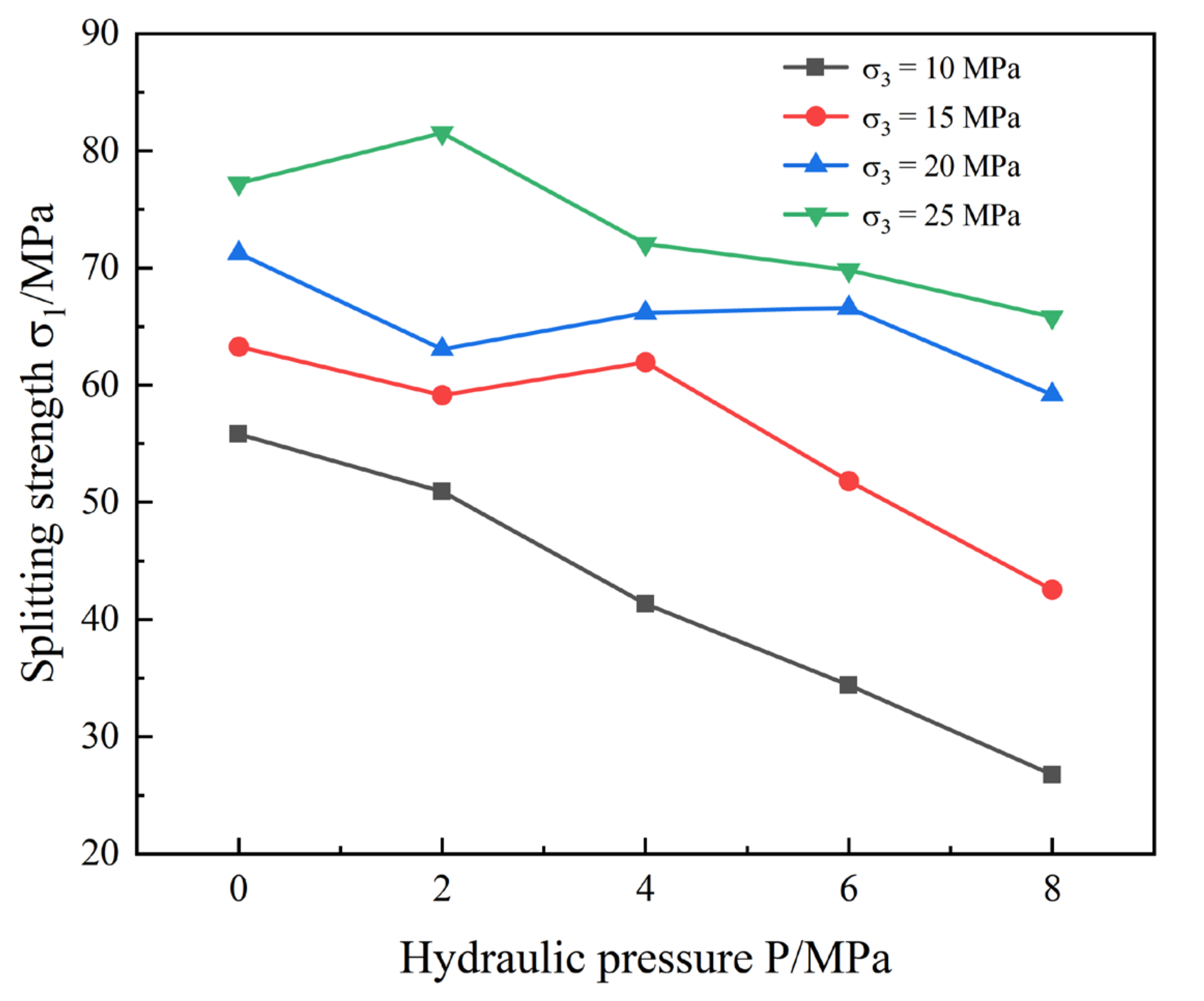
Referring to the shear fracture test data in the article of [33], a relationship curve between splitting strength values σ 1 under different P is obtained (see Figure 2). It shows that the increase of the osmotic pressure results in an approximately linear decrease of the splitting strength value. This is because the hydraulic pressure reduces the normal stress and increases the shear driving force on the crack surface. Similarly, if the hydraulic pressure decreases, the initial crack strength of rock mass will be greater, and less likely to be damaged. At the same time, the confining pressure has a significant enhancement effect on the rupture strength.
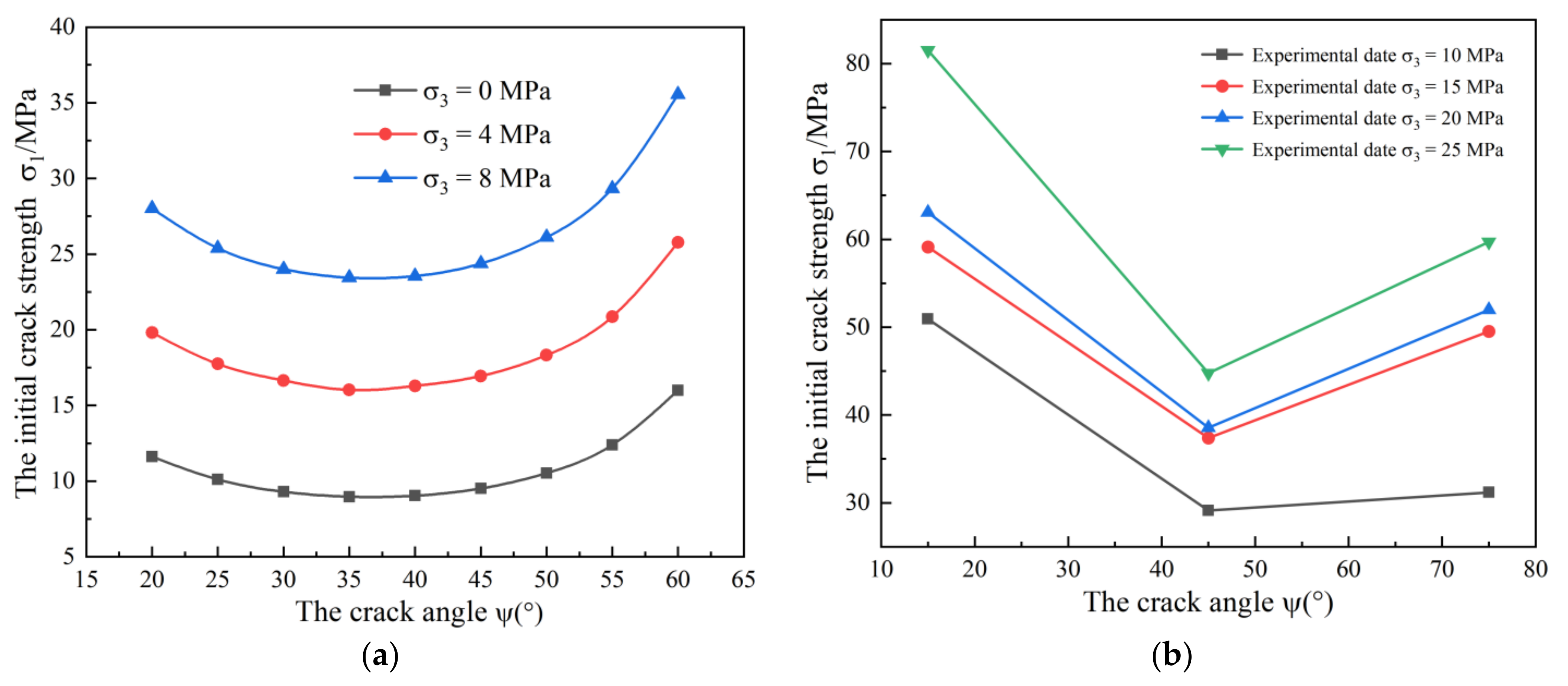
Figure 3a and Figure 4b are, respectively, the initial crack strength curves under different confining pressure and different hydraulic pressure. It is assumed that crack length a   = 2.0 m, crack connectivity β = 60%, internal friction factor μ = 0.3, the fracture toughness of rock compression shear failure crack K c = 11.2 MPa m1/2 [34], and the pressure transfer coefficient C n   , shear transfer coefficient C v   , and cohesion C are not considered. It shows that the initial crack strength is inversely proportional to the hydraulic pressure; with the increase of osmotic pressure, the initial crack strength of the fractured rock mass decreases; the crack angle ψ = 30 ° remains unchanged, when the hydraulic pressure increases from 0 to 5 MPa, the initial crack strength decreases from 18.16 to 15.65 MPa, which decreases by 13.8%; in Figure 3a, the crack angle is between 50 and 60°, and the crack initiation strength changes faster than that of the smaller initial crack angle, indicating that the hydraulic pressure has a more obvious deterioration effect on the crack initiation strength of the larger crack angle. The initial crack strength is proportional to the confining pressure, the cracking strength of the fractured rock mass increase with the increase of the confining pressure; when the crack angle ψ = 30 ° remains unchanged, the confining pressure σ 3 increases from 0 to 8 MPa, and the initial crack strength increases from 9.30 to 24.00 MPa, with an increase of 158.1%; and the initial crack strength is also relevant to the crack angle, which first decreases and then increases with the increase of the crack angle; when the crack angle ψ is approximately equal to 40°, the initiation strength is minimum. Additionally, as shown in Figure 3b and Figure 4b, the effects of hydraulic pressure, confining pressure, and the crack angle on the initial strength are consistent with the experimental data in [33].

2.2. Crack Propagation

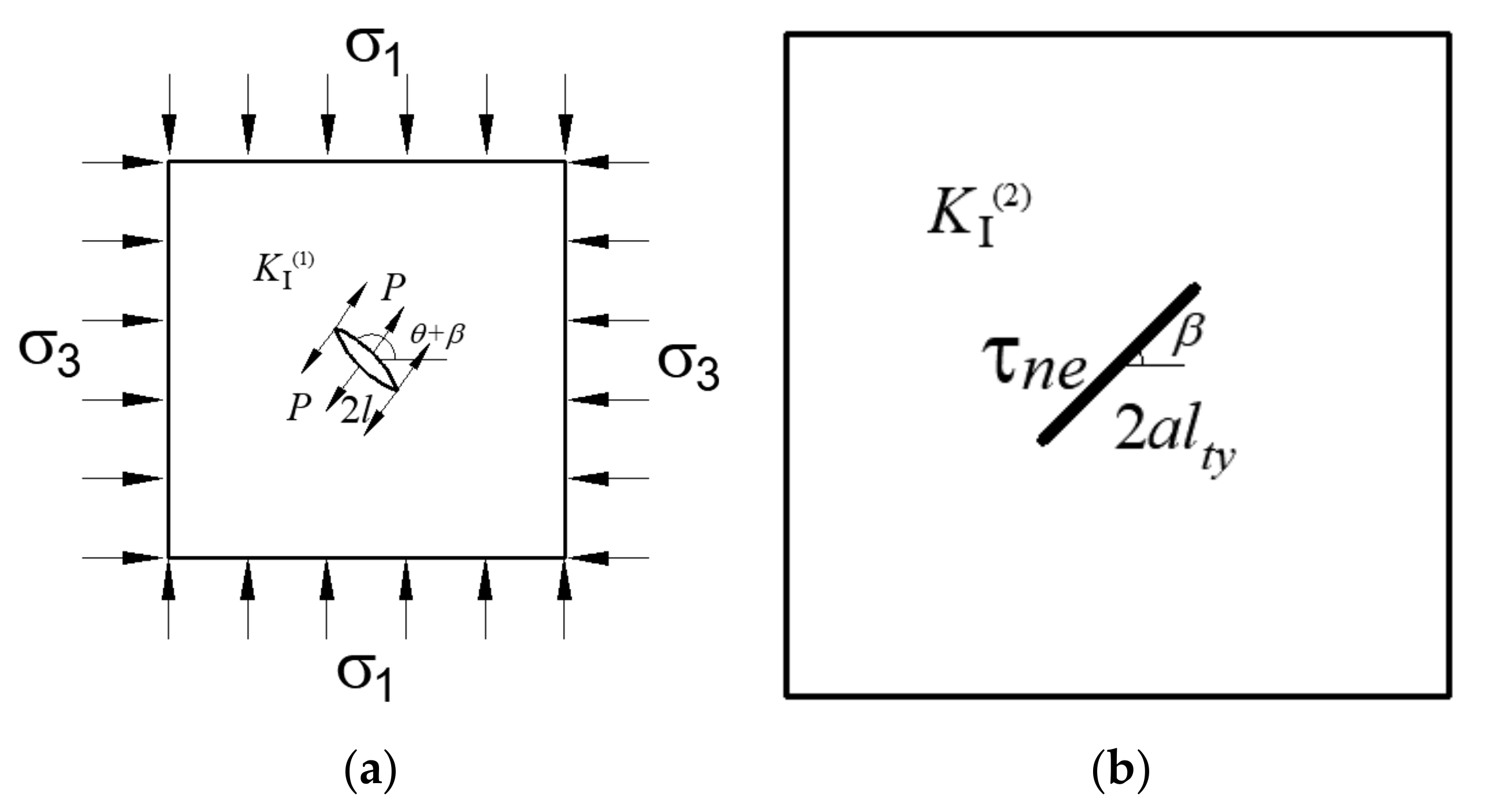
With the initiation and propagation of the wing crack, the stress intensity factor at the tip of the wing crack will evolve as it propagates. Based on the fracture mechanics [35], the stress intensity factor at the tip of the wing crack under high hydraulic pressure can be simplified into the superposition of the two stress intensity factors, as shown in Figure 5:
K = K 1 + K 2
The two wing cracks are linked up to form one isolation crack with the length of 2 l , which under the combined action of the far field stress σ 1 , σ 3 , and hydraulic pressure P , and this crack generates the stress intensity factor K 1 ; simultaneously, the component K 2 is due to effective shear stress induced by the presence of the main crack subjected to hydraulic pressure and far field stresses. The main crack length is 2 a l t y , where l t y is the influence coefficient.
According to the rock fracture mechanics criterion, the stress intensity factor K at the tip of the wing crack can be expressed as [36]:
K 1 = σ n P π l = 1 2 σ 1 + σ 3 + σ 1 σ 3 cos 2 θ + β P l π l
K 2 = 3 τ n e a l t y π sin 1 1 l t y sin θ cos θ 2
K = 3 τ e f f a l t y π sin 1 ( 1 l t y ) sin θ cos θ 2 σ n P π l
l t y = 1 + 9 l 4 a cos 2 θ 2 1 e l a + 0.667 sec 2 θ 2 e l a
σ n = 1 2 σ 1 + σ 3 + σ 1 σ 3 cos 2 θ + β
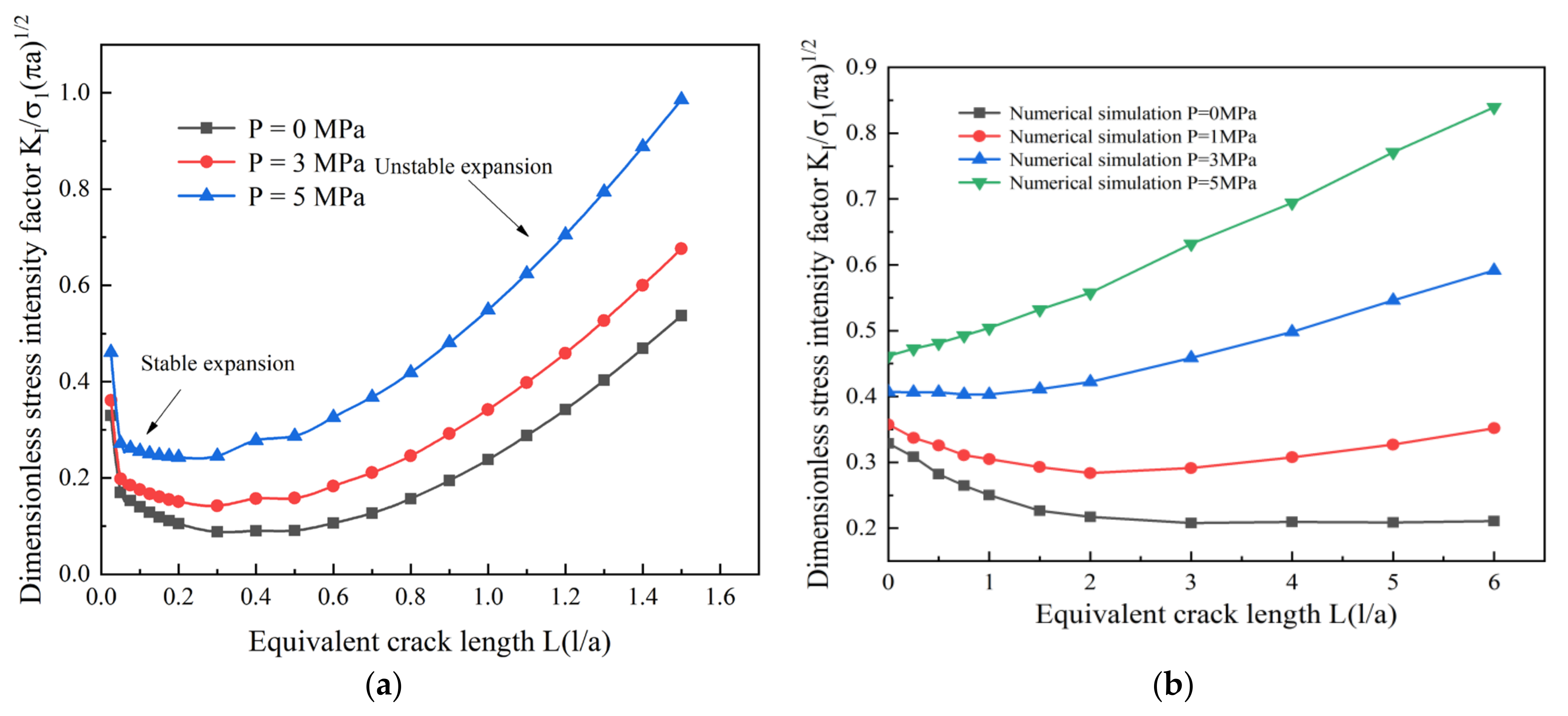
Figure 6a and Figure 7a show the variation curves of normalized stress intensity factor ( K / σ 1 π a ) at the crack tip with the equivalent crack propagation length L = l / a under different hydraulic pressure P , far-field stress σ 3 , and the crack angle ψ . It is assumed that the maximum crack initiation angle θ   = 70.5°, the crack length a   = 2.0 m, the crack connectivity β   = 60%, the friction coefficient μ   = 0.3, σ 3 = λ σ 1 , and the pressure transfer coefficient C n , shear transfer coefficient C v , and cohesion C are not considered. In order to study the evolution law of stress intensity factor of wing crack tip under different confining pressure and hydraulic pressure, it is assumed that far-field stress σ 1 = 40 MPa, and σ 3   = 0 ( λ   = 0), 4 MPa ( λ   = 0.1), and 8 MPa ( λ   = 0.2). It shows that, under other given conditions, the stress intensity factor of wing crack decreases with the increase of remote field stress σ 3 , the wing crack tends to expand stably; the stress intensity factor of wing crack increases with the increase of hydraulic pressure P , which indicates that under high hydraulic pressure, the rock crack will expand at a high speed as long as it cracks, and higher hydraulic pressure will lead to unstable expansion. As shown in Figure 6b and Figure 7b, the effects of hydraulic pressure and confining pressure on the dimensionless stress intensity factor are consistent with the ANSYS numerical simulation data in [37].

2.3. Compression Shear Fracture Theory of Zhou Qunli

For the compression-shear fracture of rock, the criterion of compression-shear fracture of Zhou Qunli [38] is proposed based on the compression-shear fracture theory of rock and combined with Mohr–Coulomb criterion.
λ 12 K + K = K c
where λ 12 is the compression-shear coefficient, K and K are the stress intensity factor of type I and stress intensity factor of type II, respectively, and K is the fracture toughness of rock. At present, the physical significance of the compression-shear constant λ 12 is not clear. At the same time, the fracture may deteriorate the rock due to the unconsidered hydraulic pressure. In this paper, the influences of hydraulic pressure, the crack angle, and far-field stress on the compression-shear constant λ 12 are analyzed based on the quasi-measurement of compression-shear fracture, and the relationship between the hydraulic crack angle, far-field stress, and compression-shear coefficient is further clarified. Equations (1) and (2) do not consider the pressure transfer coefficient C n , shear transfer coefficient C v , and coefficient C for compression-shear complex fracture. For compression-shear composite fracture, stress intensity factor I and stress intensity factor II are generated at the crack tip as shown in Equations (15) and (16). Far-field stress σ 1 is substituted by initial crack strength, and other conditions are consistent with those before. The relationship between fracture hydraulic pressure and the crack angle, far-field stress, compression shear coefficient, and stress intensity factor is obtained, as shown Figure 8, Figure 9 and Figure 10.
K = σ n e π a = σ 1 sin 2 ψ + σ 3 cos 2 ψ β P π a
K = τ e f f π a = σ 1 σ 3 2 sin 2 ψ μ σ n e π a
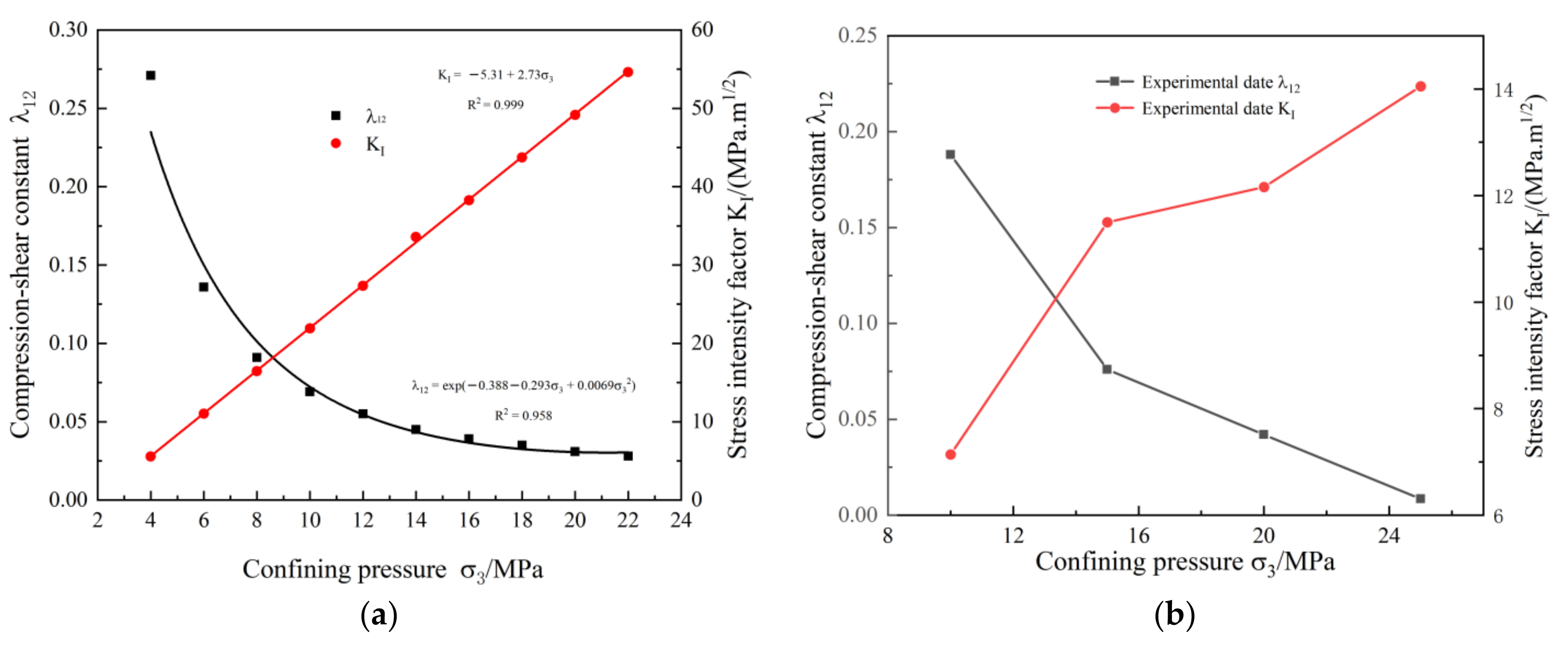
It can be seen from Figure 8a that with the increase of hydraulic pressure, the overall stress intensity factor of type I increases linearly, and the hydraulic pressure increases from 0 to 9 MPa. The stress intensity factor of type II decreases from 24.64 to 9.90 MPa, a decrease of 59.8%, indicating that the normal compressive stress was reduced due to the presence of hydraulic pressure, resulting in a small press-shear stress intensity factor. With the increase of hydraulic pressure, the compression-shear coefficient increases faster and faster, showing the law of exponential functions. The stress intensity factor of type II increases with the increase of confining pressure and shows a linear growth law, indicating that the confining pressure promotes the normal compressive stress from 4 to 22 MPa. With the increase of confining pressure, the compression-shear coefficient gradually decreases and decreases more and more slowly, showing the law of exponential function reduction, as shown in Figure 9a. When the confining pressure increases from 4 to 10 MPa, the compression-shear coefficient decreases from 0.271 to 0.069, decreasing by 74.5%; while when the confining pressure increases from 14 to 22 MPa, the compression-shear coefficient decreases from 0.045 to 0.028, decreasing only by 37.7%, indicating that low confining pressure has a greater influence on the compression-shear coefficient. Figure 10a shows that the compression-shear coefficient nearly linearly decreases with the increase of the crack angle. However, the influence of the crack angle on the stress intensity factor of type I is different from that of the confining pressure, showing the exponential functions law increases on the whole. By calculation, for stress intensity factor of type II, the hydraulic pressure confining pressure and the crack angle show no correlation regularity, and the stress intensity factor of type II remains unchanged at about 9.7 Mpa m1/2. It is further shown that the cracks are mainly extended according to type I, and in a sense, it can be considered that a compound type I and type II crack can be equated to a pure type I crack. As shown in Figure 8b, Figure 9b, and Figure 10b, the effects of hydraulic pressure, confining pressure, and the crack angle on the compression-shear constant and stress intensity factor are consistent with the experimental data in [33].
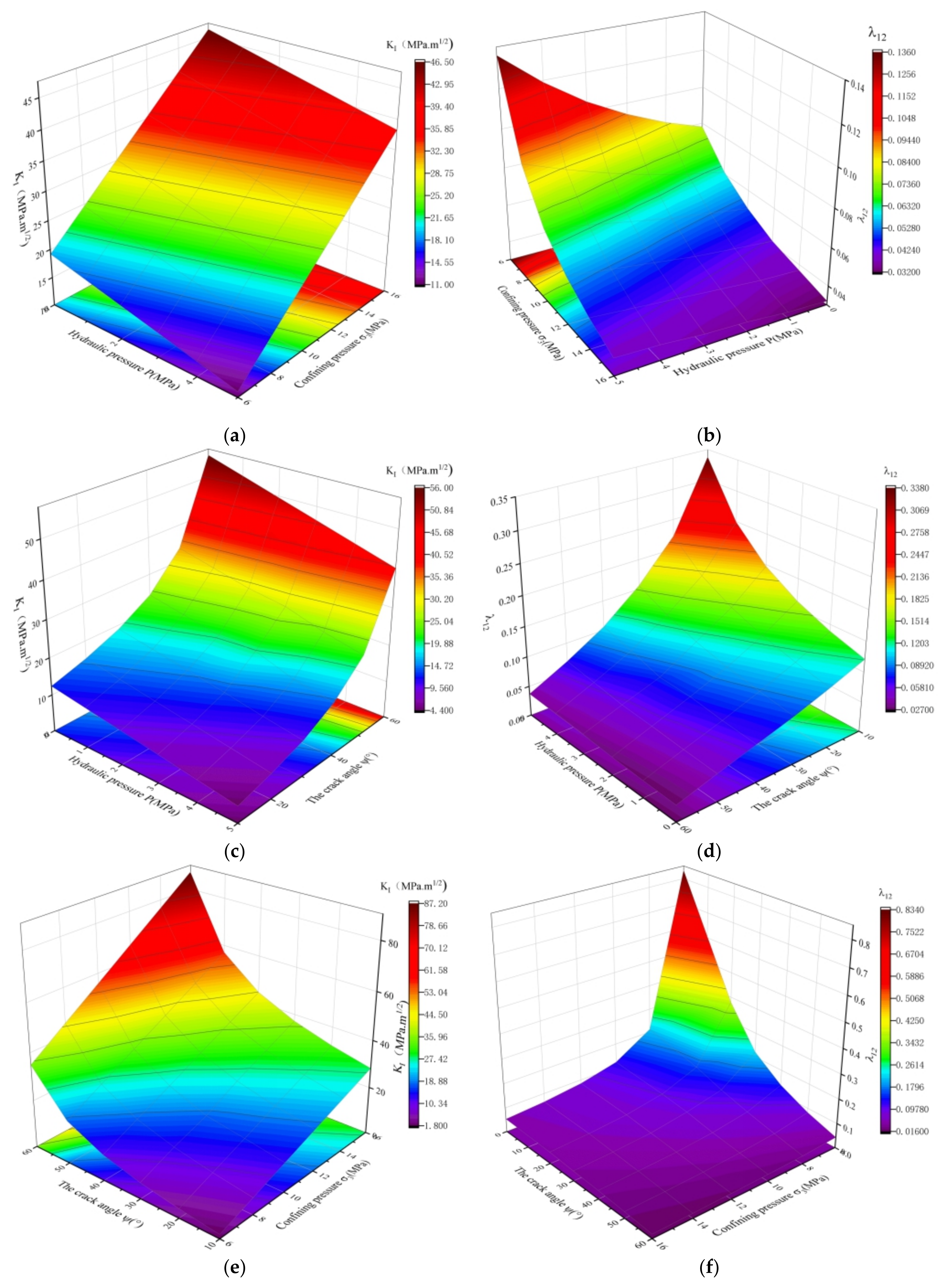
To further understand the coupling effect of three factors, namely, the confining pressure, hydraulic pressure, and the crack angle, on the stress intensity factor and the compressive shear coefficient, see Figure 11. In general, the smaller the hydraulic pressure, the larger the confining pressure, and the larger the crack angle, the higher the stress intensity factor value, while the compression shear factor shows the opposite; in addition, the effects of hydraulic pressure and confining pressure on the stress intensity factor show a linear law, while the crack angle shows an exponential function growth law, while all three factors show a nonlinear relationship with the compression shear factor. In particular, when the coupling effect of confining pressure and the crack angle on the compression shear factor is taken into consideration, it shows the approximate linear law on the compression shear factor under the condition of high confining pressure and large crack angle; on the contrary, the compression shear factor increases abruptly under the condition of low confining pressure and small the crack angle.

3. Analysis the Failure Type of Crag Bridge

A large number of cracks exist in rock mass, and far-field stress increases and cracks expand and penetrate each other. The hydraulic pressure into the fracture splitting effects of the crack and the crag bridge between shear capacity has been weakened, nevertheless rock mass mechanics have deteriorated, thus leading to mutual penetration between cracked rock damage. In addition, the crack inter-permeation pattern is varied in this paper, and the failure modes of the crag bridge wing crack-wing crack, wing crack-shear crack-wing crack, wing crack-shear crack, shear crack-shear crack and failure criterion are introduced.

3.1. Wing Crack-Wing Crack Failure Mode

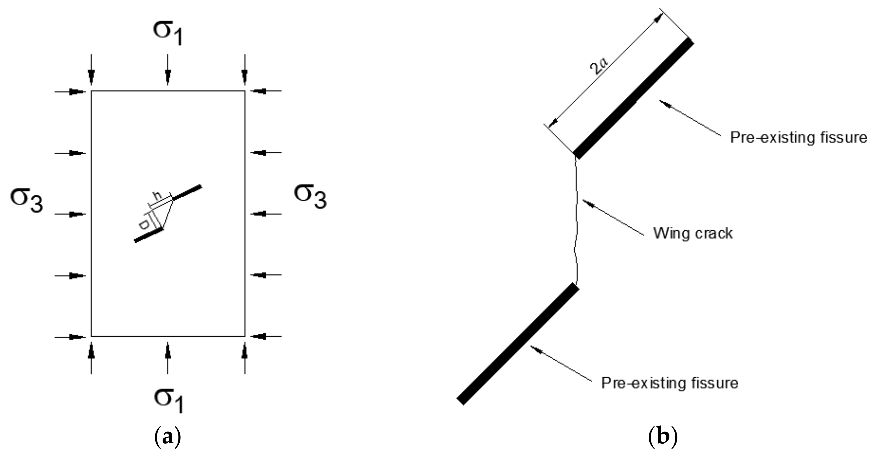
During the loading process, a wing crack is generated at the prefabricated crack tip. The wing crack expands stably in the direction of maximum compressive stress and connects with another wing crack at the prefabricated crack tip. The crag bridge breaks through and forms a macroscopic fracture surface. In Figure 12, 2 a is the length of the prefabricated crack, D is the vertical direction of the two prefabricated cracks, and h is the distance between the horizontal plane of the two prefabricated cracks. The stress intensity factor K of the wing crack tip satisfies K 0 < K < K c   ; the length of the cracks at both ends l 1 t and l 2 t are a function of time t , and it is assumed that the cracks at both ends propagate in the same way. When the l 1 < l 1 c   l 1 c = 1 2 D 2 + h 2 , no penetrating failure occurred in the rock bridge within time t ; when l 1 = l 1 c   , the stress intensity factor K = K c at the crack tip, and the crag bridge breaks through.
In simultaneous Equations (11) and (12), the stress intensity factor of the crack tip is obtained when the wing crack reaches the critical length.
K l 1 c = 3 τ e f f a l t y l 1 c π sin 1 ( 1 l t y l 1 c ) sin θ cos θ 2 σ n P π l 1 c
l t y l 1 c = 1 + 9 l 1 c 4 a cos 2 θ 2 1 e l 1 c a + 0.667 sec 2 θ 2 e l 1 c a
l 1 c = 1 2 D 2 + h 2

3.2. Wing Crack-Shear Crack-Wing Crack Failure Mode

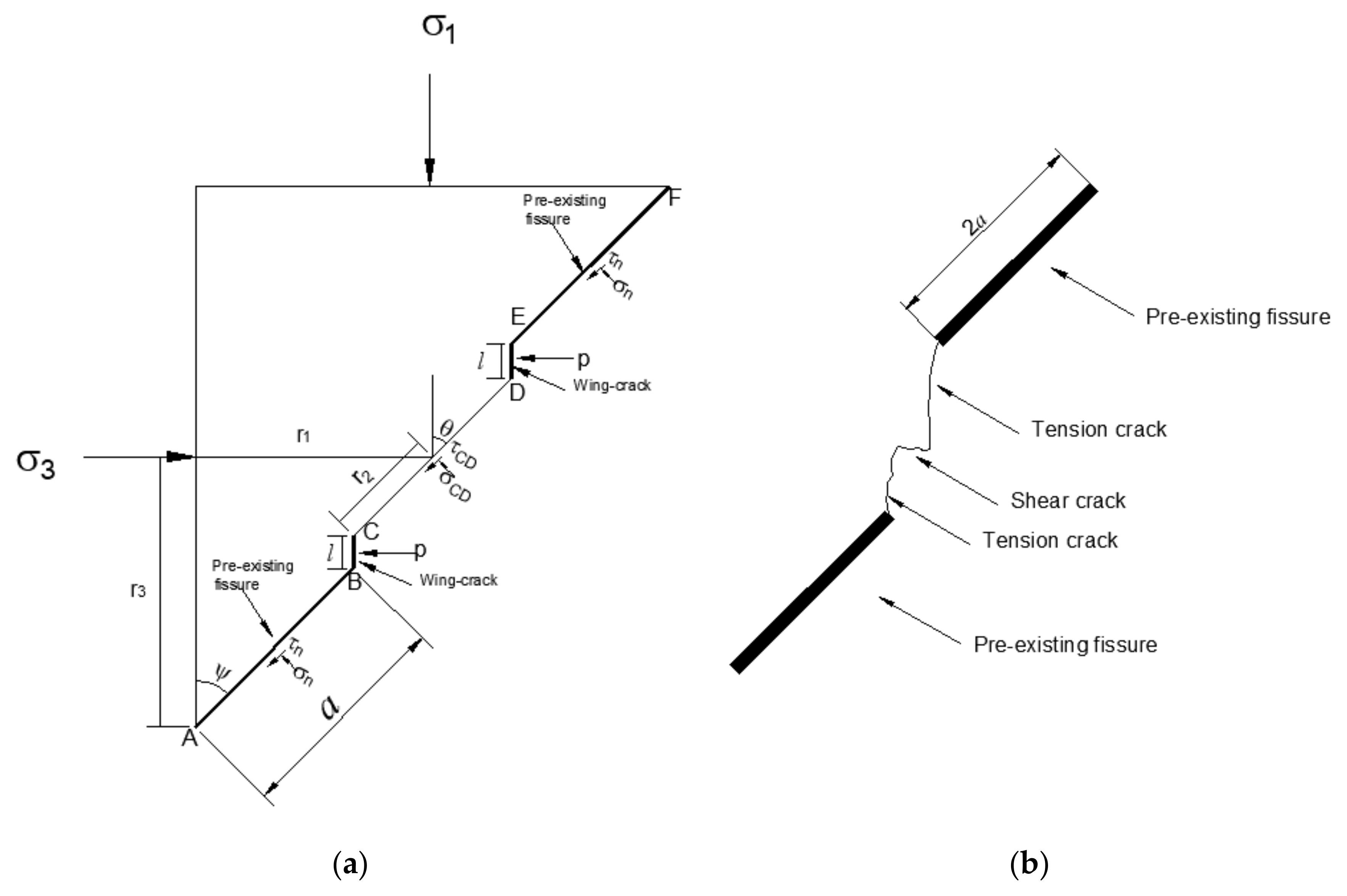
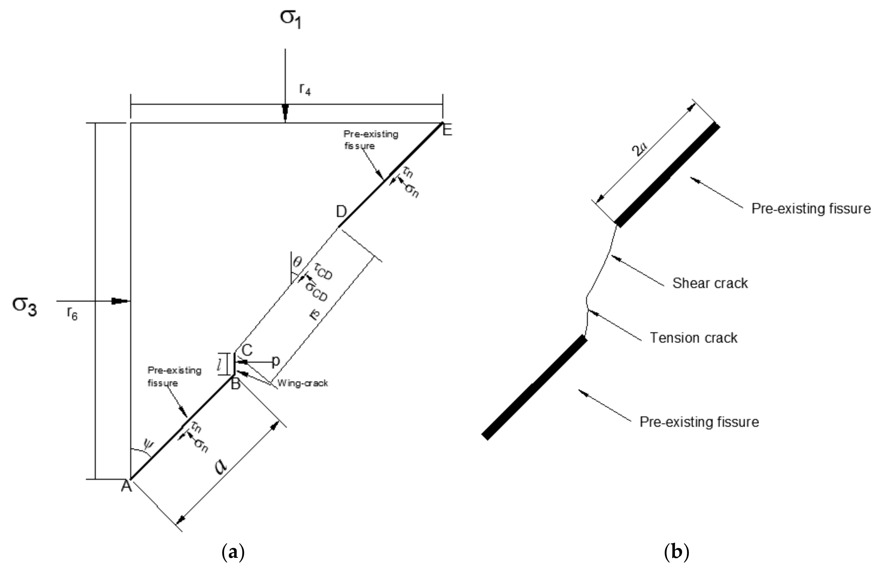
This type of crag bridge connection mostly occurs when the prefabricated cracks have a large dip angle. According to the theory of maximum axial stress, the maximum crack initiation angle of type I stress intensity factor is about 70.5°, and the crack initiation angle has nothing to do with the prefabricated crack angle. When the inclination angle of the prefabricated crack increases, the angle between the direction of wing crack initiation and the direction of maximum compressive stress increases, and the compressive stress has an obvious inhibitory effect on the propagation of wing crack, which makes it difficult to generate and develop the wing crack at the prefabricated crack tip of rock sample [23]. Therefore, in the loading process, the prefabricated crack tip produces wing cracks, moreover the wing cracks are difficult to expand in the direction of maximum compressive stress, meanwhile shear cracks occur between wing cracks, and the rock bridge is broken through eventually.
In Figure 13, A B and E F are half of the upper and lower prefabricated cracks, respectively, and length is equal to a , C B and D E are wing cracks, and C D is the crag bridge. τ n and σ n are the normal stress and shear stress acting on the prefabricated crack. τ C D and σ C D are the normal stress and shear stress acting on the bridge, and hydraulic pressure P acts on the two wings [36,39,40].
F x = 0 , F y = 0
2 r 3 σ 3 2 a ( τ n sin ψ + σ n cos ψ ) 2 r 2 ( τ C D sin θ + σ C D cos θ ) 2 P l = 0 2 r 1 σ 1 + 2 a τ n cos ψ σ n sin ψ + 2 r 2 τ C D cos θ σ C D sin θ = 0
In Equation (21):
r 1 = a sin ψ + 1 2 D 2 + h 2 sin θ   r 2 = 1 2 D 2 + h 2 l cos θ r 3 = a cos ψ + 1 2 D 2 + h 2 cos θ θ = ψ a r c tan D h
Simultaneous Equations (20)–(22) can be obtained:
τ C D = 2 A 1 tan θ 2 B 1 ( D 2 + h 2 cos θ 2 l ) 1 + tan 2 θ
σ C D = 2 A 1 + 2 B 1 tan θ ( D 2 + h 2 cos θ 2 l ) 1 + tan 2 θ
A 1 = r 3 σ 3 a ( τ n sin ψ + σ n cos ψ ) P l B 1 = r 1 σ 1 + a τ n cos ψ σ n sin ψ
With the extension of wing crack length, the shear strength between the crag bridge is weakened, which leads to the bridge being cut through. It is assumed that the crag bridge failure conforms to the Mohr–Coulomb strength criterion, then the failure conditions are as follows:
τ C D c σ C D tan φ 0
Simultaneous Equations (23)–(26) can be obtained:
1 2 D 2 + h 2 cos θ l c tan 2 θ + B 1 tan φ A 1 tan θ + A 1 tan φ + B 1 + 1 2 c D 2 + h 2 cos θ c l 0
If Equation (27) has roots that satisfy the root discriminant:
tan θ A 1 B 1 tan φ Δ D 2 + h 2 cos θ 2 l ) c , A 1 B 1 tan φ + Δ D 2 + h 2 cos θ 2 l ) c
The crack length l increases with the increase of θ angle. When the crag bridge inclination angle reaches θ c and the crack growth length reaches critical value l c , then:
θ c = arc tan A 1 B 1 tan φ + Δ D 2 + h 2 cos θ 2 l 2 c c
It can be seen from the geometric relationship of element body in Figure 13 that:
tan θ c = D 2 + h 2 sin θ D 2 + h 2 cos θ 2 l 2 c
Simultaneous Equations (29) and (30) can be obtained:
l 2 c = E 1 E 1 2 c + P tan θ F 1 2 c + P tan φ
In Equation (31):
E 1 = r 3 σ 3 tan φ a τ n sin φ + σ n cos φ tan φ + B 1 + 1 2 D 2 + h 2 ( 2 c P tan φ ) cos θ + P sin θ
F 1 = D 2 + h 2 c + 2 D 2 + h 2 ( r 3 σ 3 a τ n sin ψ a σ n cos φ ) ( cos θ tan φ sin θ ) + B 1 ( sin θ tan φ + cos θ )
The length of cracks at both l 3 t and l 4 t ends are a function related to time t , and it is assumed that cracks at both ends propagate in the same way. If l 3 t = l 4 t , when l 3 t < l 2 c   , the rock does not coalesce at time t ; when l 3 t = l 2 c   K = K c   , the rock crag breaks through.
In simultaneous Equations (11), (12), and (31), the stress intensity factor of the crack tip is obtained when the wing crack reaches the critical length.
K l 2 c = 3 τ e f f a l t y l 2 c π sin 1 ( 1 l t y l 2 c ) sin θ cos θ 2 σ n P π l 2 c
l t y l 2 c = 1 + 9 l 2 c 4 a cos 2 θ 2 1 e l 2 c a + 0.667 sec 2 θ 2 e l 2 c a

3.3. Wing Crack-Shear Crack Failure Mode

During the loading process, the prefabricated crack generates a wing crack, which expands stably in the direction of maximum compressive stress. When the wing crack expands to a certain extent, it is connected with another shear crack generated by the prefabricated crack, and finally the crag bridge is connected to form a macroscopic fracture surface.
F x = 0 , F y = 0
r 6 σ 3 2 a ( τ n sin ψ + σ n cos ψ ) r 5 ( τ C D sin θ + σ C D cos θ ) P l = 0 r 4 σ 1 + 2 a τ n cos ψ σ n sin ψ + r 5 τ C D cos θ σ C D sin θ = 0
In Equation (37):
r 4 = 2 a sin ψ + D 2 + h 2 sin θ   r 5 = D 2 + h 2 l cos θ r 6 = 2 a cos ψ + D 2 + h 2 cos θ
Simultaneous Equations (36)–(38) can be obtained:
τ C D = 2 A 2 tan θ 2 B 2 ( D 2 + h 2 cos θ l ) 1 + tan 2 θ
σ C D = 2 A 2 + 2 B 2 tan θ ( D 2 + h 2 cos θ l ) 1 + tan 2 θ
A 2 = 1 2 r 3 σ 3 a ( τ n sin ψ + σ n cos ψ ) 1 2 P l B 2 = 1 2 r 1 σ 1 + a τ n cos ψ σ n sin ψ
With the extension of wing crack length, the shear strength between crag bridge is weakened, which leads to the bridge being cut through. It is assumed that crag bridge failure conforms to the Mohr–Coulomb strength criterion, then the failure conditions are as follows:
τ C D c σ C D tan φ 0
Simultaneous Equations (39)–(42) can be obtained:
1 2 D 2 + h 2 cos θ 1 2 l c tan 2 θ + B 2 tan φ A 2 tan θ + A 2 tan φ + B 2 + 1 2 c D 2 + h 2 cos θ 1 2 c l 0
If Equation (43) has roots that satisfy the root discriminant:
tan θ A 2 B 2 tan φ Δ D 2 + h 2 cos θ l ) c , A 2 B 2 tan φ + Δ D 2 + h 2 cos θ l ) c
The crack length l increases with the increase of θ angle. When the crag bridge inclination angle reaches θ c and the crack growth length reaches critical value l c , then:
θ c = arc tan A 2 B 2 tan φ + Δ D 2 + h 2 cos θ l 3 c c
It can be seen from the geometric relationship of the element body in Figure 14 that:
tan θ c = D 2 + h 2 sin θ D 2 + h 2 cos θ l 3 c
Simultaneous Equations (45) and (46) can be obtained:
l 3 c = E 2 E 2 2 c + P tan θ F 2 c + P tan φ
In Equation (47):
E 2 = 1 2 r 6 σ 3 tan φ a τ n sin φ + σ n cos φ tan φ + B 2 + 1 2 D 2 + h 2 ( 2 c P tan φ ) cos θ + P sin θ
F 2 = D 2 + h 2 c + 2 D 2 + h 2 ( 1 2 r 3 σ 3 a τ n sin ψ a σ n cos φ ) ( cos θ tan φ sin θ ) + B 2 ( sin θ tan φ + cos θ )
It is assumed that crack l 5 t is a function related to time t . When l 5 t < l 3 c   , the crag bridge is not connected at time t . When l 5 t = l 3 c   , the stress intensity factor K = K c , the crag bridge is broken through.
In simultaneous Equations (11), (12), and (47), the stress intensity factor of the crack tip is obtained when the wing crack reaches the critical length.
K l 3 c = 3 τ e f f a l t y l 3 c π sin 1 ( 1 l t y l 3 c ) sin θ cos θ 2 σ n P π l 3 c
l t y l 3 c = 1 + 9 l 3 c 4 a cos 2 θ 2 1 e l 3 c a + 0.667 sec 2 θ 2 e l 3 c a

3.4. Shear Crack-Shear Crack Failure Mode

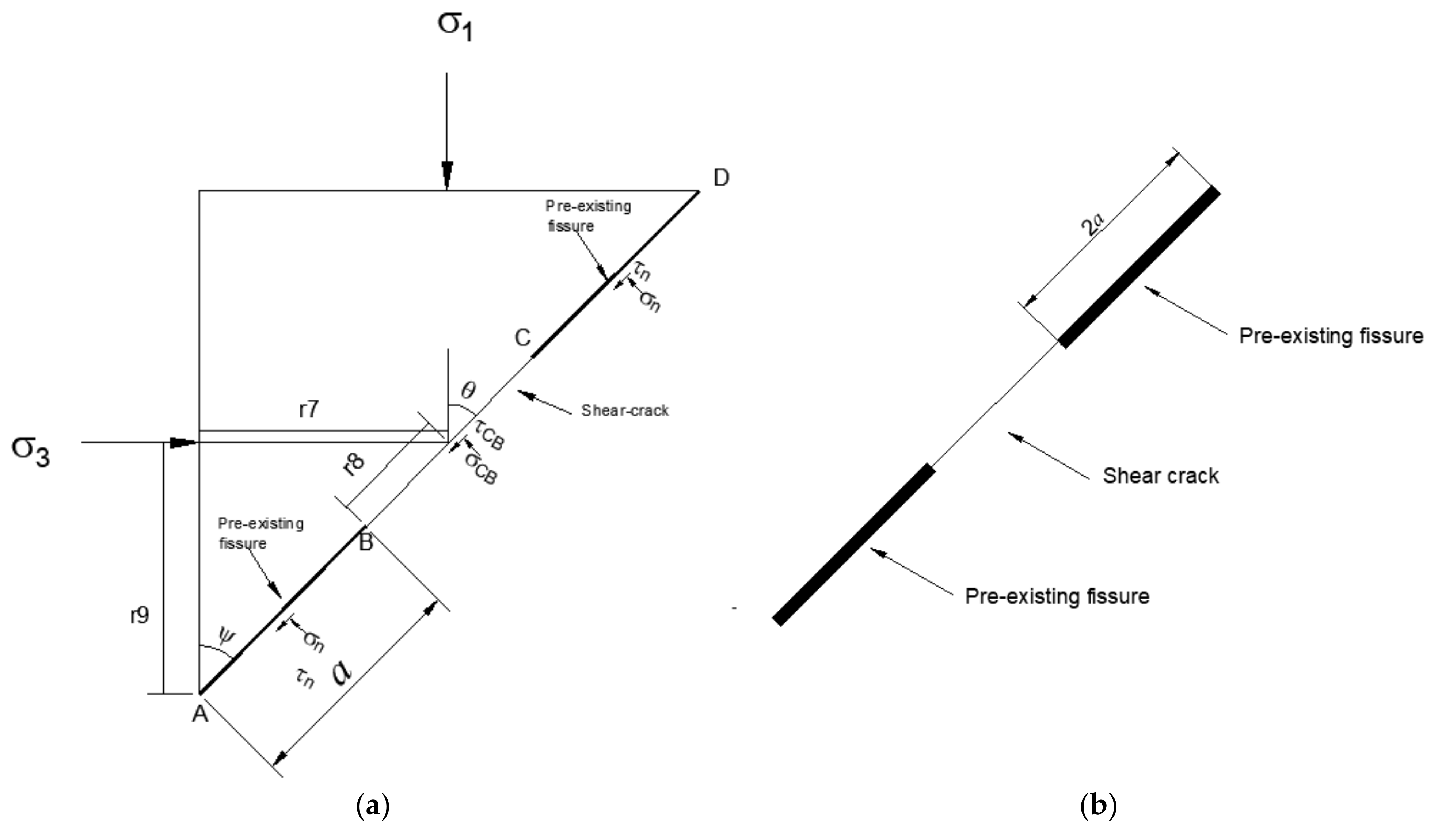
This crag bridge failure mode occurs in the case of coplanar prefabricated cracks. With the increase of load, shear cracks appear in the inner ends of the two precast cracks. When the cracks grow to a certain length, the rock bridge breaks through, forming a macroscopic shear fracture surface (see Figure 15).
F x = 0 , F y = 0
2 r 9 σ 3 2 a ( τ n sin ψ + σ n cos ψ ) 2 r 8 ( τ C D sin θ + σ C D cos θ ) = 0 2 r 7 σ 1 + 2 a τ n cos ψ σ n sin ψ + 2 r 8 τ C D cos θ σ C D sin θ = 0
In Equation (53):
r 7 = a sin ψ + 1 2 D 2 + h 2 sin θ   r 2 = 1 2 D 2 + h 2 r 3 = a cos ψ + 1 2 D 2 + h 2 cos θ θ = ψ
Simultaneous Equations (52)–(54) can be obtained:
τ C D = 2 A 3 tan θ 2 B 3 D 2 + h 2 cos θ 1 + tan 2 θ
σ C D = 2 A 3 + 2 B 3 tan θ D 2 + h 2 cos θ 1 + tan 2 θ
A 3 = r 9 σ 3 a ( τ n sin ψ + σ n cos ψ ) B 3 = r 7 σ 1 + a τ n cos ψ σ n sin ψ
With the extension of wing crack length, the shear strength between crag bridge is weakened, which leads to the crag bridge being cut through. It is assumed that the crag bridge failure conforms to the Mohr-Coulomb strength criterion, then the failure conditions are as follows:
τ C D c σ C D tan φ 0
Simultaneous Equations (55)–(58) can be obtained:
1 2 D 2 + h 2 cos θ c tan 2 θ + B 3 tan φ A 3 tan θ + A 3 tan φ + B 3 + 1 2 c D 2 + h 2 cos θ 0
If Equation (59) has roots that satisfy the root discriminant:
tan θ A 3 B 3 tan φ Δ D 2 + h 2 cos θ c , A 3 B 3 tan φ + Δ D 2 + h 2 cos θ c
The maximum crack angle of shear crack-shear crack failure mode is as follows:
θ c = arc tan A 3 B 3 tan φ + Δ D 2 + h 2 cos θ c
According to [31], when the prefabricated fracture dip angle is equal to the rock bridge dip angle, and with the increase of prefabricated fracture angle, this failure mode occurs with more difficulty. Therefore, it can be seen that shear crack-shear crack failure mode occurs less easily when rock crag inclination is ψ than θ c .
It can be seen that for type II cracks (shear cracks), the crack expansion in shear. From Equations (55) and (56), it is known that K is independent of the osmotic pressure. Therefore, if the crack occurs as a type II shear crack, it is not related to the osmotic pressure. Hydraulic pressure only has a splitting effect on the wing crack. Compared with the four failure modes, the wing crack-shear crack-wing crack mode has a greater impact on the rock failure and the rock crag is broken through in less time.

4. Conclusions

Hydraulic pressure field and stress field interaction is an important characteristic of rock which cannot be ignored. Seepage fluid pressure changes the stress state on the crack surface, and aggravates the trend of the micro-fracture and the faulty degradation of the fractured rock mass. According to the rock fracture mechanics criterion, the initiatory cracking law and evolution law of the stress intensity factor at the tip of the wing crack concerning the compressive-shear fractured rock under high hydraulic pressure are discussed, and the critical hydraulic pressure value, initial crack intensity criterion, and the wing crack propagation mechanics model are studied when compression-shear failure occurred and four rock-bridge fracture damage criteria are established. Besides, the relationship between compression shear coefficient of the Zhou Qunli compression shear theory and hydraulic pressure, confining pressure and the crack angle is also explored. The following conclusions were obtained.
(1) Theory results indicate that crack initiation strength is inversely proportional to hydraulic pressure, the existence of hydraulic pressure aggravates the wing crack’s growth, and the action of the wing crack under high hydraulic pressure extends from stable expansion into unstable expansion; the rock mass strength is proportional to the confining pressure, the stress intensity factor of wing cracks decrease with the increase of remote field stress σ 3 , and the wing crack tends to expand stably; the cracking strength decreases initially, then increases as the crack angle increases. This theory will provide the basis for the economic and efficient investigation of the compressive-shear destruction of fractured rock under high hydraulic pressure.
(2) Based on the criterion of compression-shear fracture of Zhou Qunli, the hydrodynamic coupling action of fractured rock compression shear fracture criterion is established, and the relationship between the compression shear coefficient λ 12 and hydraulic pressure, confining pressure, and the crack angle is clarified, and it is found that they are correlated with the stress in tensity factor K , while the stress intensity factor K maintains a relatively constant value. The smaller the hydraulic pressure, the larger the confining pressure, and the larger the crack angle, the higher the stress intensity factor K value, while the compression shear factor shows the opposite. In addition, the effects of hydraulic pressure and confining pressure on the stress intensity factor K show a linear law, while the crack angle shows an exponential function growth law, and all three factors show a nonlinear relationship with the compression shear factor λ 12 .
(3) The critical crack initiation angle, critical length of wing crack, and critical stress intensity factor of rock crag penetration damage are derived for the four types of rock crag shear damage, which mainly occur in wing crack, shear crack, and wing crack-shear crack mode penetration under high hydraulic pressure. In addition, when the values of the rock crag angle and the crack angle are equal, the rock crag is prone to pure shear penetration, and the high hydraulic pressure only has a splitting effect on the wing crack, and the mode is less likely to occur as the fracture dip becomes larger.
(4) This study did not adopt the damage mechanics theory to further establish the evolution equation of the permeability tensor under high hydraulic pressure, and only explored the crack initiation and wing crack expansion law of rock crack under compression-shear stress state and high hydraulic pressure, as well as the establishment of the compression-shear wing crack expansion model, but did not analyze the tensile-shear stress state. Similarly, there are many kinds of crag bridge damage fracture modes; this study gives four kinds of crag bridge damage mode criterion quasi-measurements, and further research is needed for follow-up.

Author Contributions

T.L., C.Z. and M.C. provided theoretical ideas; Y.S. wrote and modified the paper; Q.L. and Z.Y. Funding acquisition, P.C. provided the publication fee for the paper. All authors have read and agreed to the published version of the manuscript.

Funding

This work was financially supported by the National Natural Science Foundation of China under grant No. 52004327.

Institutional Review Board Statement

Not applicable.

Informed Consent Statement

Not applicable.

Data Availability Statement

The source date can be obtained in the article.

Conflicts of Interest

The authors declare no conflict of interest.

References

  1. Leonards, W. Modified hypothesis for failure of malpasset dam. Eng. Geol. 1987, 24, 367–394. [Google Scholar]
  2. Muller, L. The rock slide in the Vajont Valley. Eng. Geol. 1964, 2, 148–212. [Google Scholar]
  3. Tang, C.; Tham, L.; Lee, P.; Yang, H.; Li, L. Coupled analysis of flow, stress and damage (FSD) in rock failure. Int. J. Rock Mech. Min. Sci. 2002, 39, 477–489. [Google Scholar] [CrossRef]
  4. Tang, S.; Liu, X.; Luo, J.; Dong, Z. Theoretical model for tensile and shear crack initiation at the crack tip in rock subjected to hydraulic pressure. Chin. J. Rock Mech. Eng. 2017, 36, 2124–2135. [Google Scholar]
  5. Cao, P.; Liu, T.; Pu, C.; Lin, H. Crack propagation and coalescence of brittle rock-like specimens with pre-existing cracks in compression. Eng. Geol. 2015, 187, 113–121. [Google Scholar] [CrossRef]
  6. Li, B.; Zhu, Z.; Zhou, Z. A failure criterion for cracked rock mass under seepage pressure and confining pressure. Adv. Mater. Res. 2011, 225–226, 937–940. [Google Scholar] [CrossRef]
  7. Zhang, G.; Liao, X. Influence of seepage on the stability of rock slope-coupling of seepage and deformation by DDA method. Chin. J. Rock Mech. 2003, 22, 1269–1275. [Google Scholar]
  8. Jing, L.; Ma, Y.; Fang, Z. Modeling of fluid flow and solid deformation for fractured rocks with discontinuous deformation analysis (DDA)method. Int. J. Rock. Min. Sci. 2001, 38, 343–355. [Google Scholar] [CrossRef]
  9. Li, W.; Liu, Y.; Yao, X.; Chu, J.; Chen, X.; Tan, Z. Study on breakdown pressure in hydraulic fracturing process of hard rock based on numerical simulation. Geotech. Geol. Eng. 2021, 39, 909–917. [Google Scholar] [CrossRef]
  10. Yuan, Z.; Wang, H.; Liu, N. Numerical simulation of hydraulic fracture propagation characteristics of low permeable coal-rock mass. Adv. Mater. Res. 2012, 482–484, 1668–1671. [Google Scholar] [CrossRef]
  11. Liu, B. Experimental research of fine sandstone strength and deformation characteristics under different confining and hydraulic pressure. Appl. Mech. Mater. 2013, 353–356, 562–570. [Google Scholar] [CrossRef]
  12. Huang, W.; Wang, H.; Zhang, T.; He, M.; Yan, L. Hydraulic pressure effect on mechanical properties and permeabilities of layered rock mass: An experimental study. Eur. J. Environ. Civ. Eng. 2020, 1–12. [Google Scholar] [CrossRef]
  13. Wong, L.N.Y.; Einstein, H.H. Crack coalescence in molded gypsum and carrara marble: Part 1. macroscopic observations and interpretation. Rock Mech. Rock Eng. 2009, 42, 475–511. [Google Scholar] [CrossRef]
  14. Park, C.; Bobet, A. Crack initiation, propagation and coalescence from frictional flaws in uniaxial compression. Eng. Fract. Mech. 2010, 77, 2727–2748. [Google Scholar] [CrossRef]
  15. Yang, S.; Jing, H.; Wang, S. Experimental investigation on the strength, deformability, failure behavior and acoustic emission locations of red sandstone under triaxial compression. Rock Mech. Rock Eng. 2012, 45, 583–606. [Google Scholar] [CrossRef]
  16. Ashby, M.; Sammis, C. The damage mechanics of brittle solids in compression. Pure Appl. Geophys. 1990, 133, 489–521. [Google Scholar] [CrossRef]
  17. Yang, T.; Tham, L.; Tang, C.; Liang, Z.; Sui, Y. Influence of heterogeneity of mechanical properties on hydraulic fracturing in permeable rocks. Rock Mech. Rock Eng. 2004, 37, 251–275. [Google Scholar] [CrossRef]
  18. He, M.; Miao, J.; Feng, J. Rock burst process of limestone and its acoustic emission characteristics under true-triaxial unloading conditions. Int. J. Rock Mech. Min. Sci. 2010, 47, 286–298. [Google Scholar] [CrossRef]
  19. Li, X.; He, X.; Chen, H. Crack initiation characteristics of opening-mode crack embedded in rock-like material under seepage pressure. Chin. J. Rock Mech. Eng. 2012, 31, 1317–1324. [Google Scholar]
  20. Lajtai, E.; Carter, B.; Ayari, M. Criteria for brittle fracture in compression. Eng. Fract. Mech. 1990, 37, 59–74. [Google Scholar] [CrossRef]
  21. Liu, T.; Ping, C.; Hang, L. Evolution procedure of multiple rock cracks under seepage pressure. Math. Probl. Eng. 2013, 2013, 211–244. [Google Scholar] [CrossRef] [Green Version]
  22. Leung, K.; Pan, Z.; Warner, D. Kohn-Sham density functional theory prediction of fracture in silicon carbide under mixed mode loading. Model. Simul. Mater. Sci. Eng. 2016, 24, 35004. [Google Scholar] [CrossRef]
  23. Ilawe, N.; Zimmerman, J.; Wong, B. Breaking badly: Dft-d2 gives sizeable errors for tensile strengths in palladium-hydride solids. J. Chem. Theory Comput. 2015, 11, 5426–5435. [Google Scholar] [CrossRef]
  24. Zhao, X.; Cai, M.; Wang, J.; Ma, L. Damage stress and acoustic emission characteristics of the beishan granite. Int. J. Rock Mech. Min. Sci. 2013, 64, 258–269. [Google Scholar] [CrossRef]
  25. Guo, K.; Yang, L.; Sheng, X.; Mei, J.; Li, B.; Zhang, B.; Yang, W.; Song, G. Fracture mechanical behavior and AE characteristics of rock-like material containing 3-D crack under hydro-mechanical coupling. Chin. J. Rock Soil Mech. 2019, 40, 4380–4390. [Google Scholar]
  26. Zhao, Y.; Cao, P.; Lin, H.; Liu, Y. Rheologic fracture mechanism and failure criterion of rock cracks under compressive-shear load with seepage pressure. Chin. J. Geotech. Eng. 2008, 30, 511–517. [Google Scholar]
  27. Zhao, Y.; Cao, P.; Wen, Y.; Yang, H.; Li, J. Damage fracture failure mechanism of compressive-shear rock cracks under seepage pressure. J. Cent. South Univ. 2008, 39, 838–844. [Google Scholar]
  28. Jamaloei, B.Y. A critical review of common models in hydraulic-fracturing simulation: A practical guide for practitioners. Theor. Appl. Fract. Mech. 2021, 113, 102937. [Google Scholar] [CrossRef]
  29. Papachristos, E. A 3D Hydro-Mechanical Discrete Element Model for Hydraulic Fracturing in Naturally Fractured Rock; Grenoble Alpes University: Grenoble, France, 2017. [Google Scholar]
  30. Ai, D.; Jiang, G.; Lam, S.; He, P.; Li, C. Automatic pixel-wise detection of evolving cracks on rock surface in video data. Autom. Constr. 2020, 119, 103378. [Google Scholar] [CrossRef]
  31. Zhao, Y. Coupling Theory of and Seepage-Damage-Fracture in Fractured Rock Masses and Its Applications; Central South University: Changsha, China, 2009. [Google Scholar]
  32. Ashby, M.; Hallam, S. The failure of brittle solids containing small cracks under compressive stress states. Acta. Metall. 1986, 34, 497–510. [Google Scholar] [CrossRef]
  33. Zhang, Y.; Liu, Q.; Liu, H.; Liao, J.; Chang, L.; Tan, T.; Song, F. Triaxial compression and acoustic emission tests on single cracked limestone and compressive-shear fracture model under hydraulic-mechanical coupling action. Chin. J. Coal Sci. Eng. 2021, 46, 3855–3868. [Google Scholar]
  34. Liu, T.; Cao, P.; Zhao, Y. The damage fracture failure mechanism of compressive-shear rock cracks under high seepage pressure. Chin. J. Rock Mech. Eng. 2012, 33, 1801–1808. [Google Scholar]
  35. Liu, T.; Ping, C.; Hang, L. Damage and fracture evolution of hydraulic fracturing in compression-shear rock cracks. Theor. Appl. Frac. Mech. 2014, 74, 55–63. [Google Scholar] [CrossRef]
  36. Liu, T.; Cao, P.; Fan, X.; Zhao, Y. Splitting failure properties of fractured rock under high water pressure. J. Cent. South Univ. 2012, 43, 2281–2287. [Google Scholar]
  37. Liu, Q. Failure Characteristics of Single-Fracture Limestone Under Hydro Mechanical Coupling and Analysis of Insidious Fault Water Inrush; Hunan University of Science and Technology: Xiangtan, China, 2019. [Google Scholar]
  38. Zhou, Q. Compress shear fracture criterion of rock and it’s application. Chin. J. Geotech. Eng. 1987, 9, 33–37. [Google Scholar]
  39. Liu, T.; Cao, P. Failure mechanisms of brittle rock under uniaxial compression. J. Theor. Appl. Mech. 2017, 47, 59–80. [Google Scholar] [CrossRef] [Green Version]
  40. Cao, P.; Cao, R.; Zhao, Y.; Zhang, K.; Fan, W. Propagation-coalescence and rheologic fracture behavior of rock cracks. Chin. J. Nonferrous Met. 2016, 26, 1737–1762. [Google Scholar]
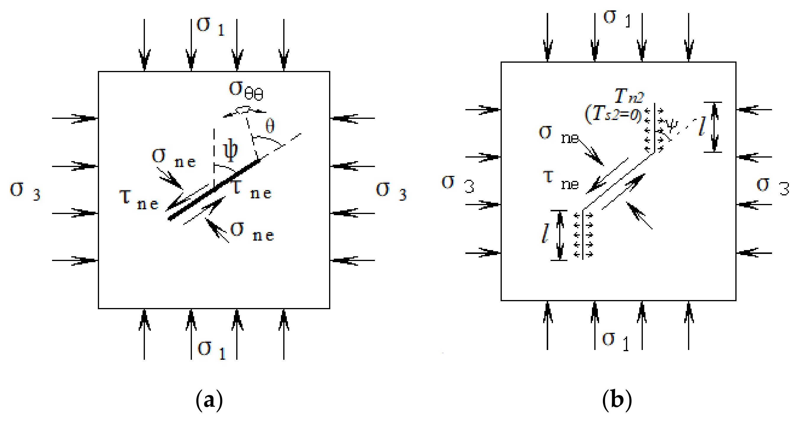
Figure 1. Sketch of wing crack initiation and propagation. (a) Wing crack starting crack; (b) wing crack extension.
Applsci 12 05846 g001
Figure 2. Splitting strength values under different hydraulic pressures [33].
Applsci 12 05846 g002
Figure 3. The crack initiation strength under different factors on hydraulic pressure. (a) Theoretical data; (b) experimental data [33].
Applsci 12 05846 g003
Figure 4. The crack initiation strength under different factors on confining pressure. (a) Theoretical data; (b) experimental data [33].
Applsci 12 05846 g004
Figure 5. Superposition of stress intensity factor of wing crack under high hydraulic pressure. (a) Wing crack stress intensity factor; (b) equivalent of crack stress intensity factor.
Applsci 12 05846 g005
Figure 6. The relationship curves between dimensional stress intensity factor at the crack tip wing stress and crack propagation length under different confining pressures. (a) Theoretical data; (b) ANSYS numerical simulation data [37].
Applsci 12 05846 g006
Figure 7. The relationship curves between dimensional stress intensity factor at the crack tip wing stress and crack propagation length under different hydraulic pressures. (a) Theoretical data; (b) ANSYS numerical simulation data [37].
Applsci 12 05846 g007
Figure 8. The relationship curves between compression-shear constant, stress intensity factor, and hydraulic pressure. (a) Theoretical data; (b) experimental data [33].
Applsci 12 05846 g008
Figure 9. The relationship curves between compression-shear constant, stress intensity factor, and confining pressure. (a) Theoretical data; (b) experimental data [33].
Applsci 12 05846 g009
Figure 10. The relationship curves between compression-shear constant, stress intensity factor, and the crack angle. (a) Theoretical data; (b) experimental data [33].
Applsci 12 05846 g010
Figure 11. Coupled action surfaces. (a) Surfaces of the coupling effect of confining pressure and hydraulic pressure on type I stress intensity factor; (b) surfaces of the coupling effect of confining pressure and hydraulic pressure on compression shear factor; (c) surfaces of the coupling effect of the crack angle and hydraulic pressure on type I stress intensity factor; (d) surfaces of the coupling effect of the crack angle and hydraulic pressure on compression shear factor; (e) surfaces of the coupling effect of the crack angle and confining pressure on type I stress intensity factor; (f) surfaces of the coupling effect of the crack angle and confining pressure on compression shear factor.
Applsci 12 05846 g011
Figure 12. Characteristics of crag bridge shear failure (wing crack—wing crack failure mode). (a) Diagram of crack force; (b) failure characteristics of crag bridge.
Applsci 12 05846 g012
Figure 13. Characteristics of crag bridge shear failure (wing crack-shear crack-wing crack failure mode). (a) Stress analysis of crag bridge; (b) failure characteristics of crag bridge.
Applsci 12 05846 g013
Figure 14. Characteristics of crag bridge shear failure (wing crack-shear crack failure mode). (a) Stress analysis of crag bridge; (b) failure characteristics of crag bridge.
Applsci 12 05846 g014
Figure 15. Characteristics of crag bridge shear failure (shear crack-shear crack failure mode). (a) Stress analysis of crag bridge; (b) failure characteristics of crag bridge.
Applsci 12 05846 g015
Publisher’s Note: MDPI stays neutral with regard to jurisdictional claims in published maps and institutional affiliations.