Article

Study on the Position Deviation between the Iron Roughneck’s Spin-Rollers and the Drilling Tool

1
School of Mechanical and Aerospace Engineering, Jilin University, Changchun 130025, China
2
Changchun Vocational Institute of Technology, Changchun 130033, China
*
Author to whom correspondence should be addressed.
Appl. Sci. 2022, 12(12), 5827; https://doi.org/10.3390/app12125827
Submission received: 8 May 2022 / Revised: 6 June 2022 / Accepted: 6 June 2022 / Published: 8 June 2022
(This article belongs to the Special Issue AI Applications in the Industrial Technologies)

Abstract

:
The spinner mechanism is one of the main working mechanisms of the iron roughneck, which is used to realize the rapid screwing-in or screwing-out of the drill pipe thread. The main problems of the spinner mechanism and the existing solutions are analyzed in this paper, and the spinner mechanism driven by a single hydraulic cylinder and transmitted by a wedge plate is designed. The upper and lower drilling tools are not concentric and affect the spin effect when the spinner mechanism works, and to address this problem, the influence of deviation in different directions is analyzed, and it is proposed that the lateral position deviation of drilling tools is the key factor affecting the spin performance. The relationship between the position deviation of the spin-roller and the position deviation of the drilling tool is established and solved. A method to reduce the lateral position deviation of drilling tools is proposed, and the effectiveness of this method is verified by experiments. The analysis shows that a spinner mechanism with a single follow-up roller easily causes the lateral position deviation of the drilling tool; the deviation of the spin-roller increases with the increase of the lateral deviation of the drilling tool, and the increase of the longitudinal deviation is more obvious; and with the increase of the drilling tool’s diameter, the deviation increases further. The symmetrical double follow-up roller structure can effectively reduce the lateral deviation of drilling tools and spin-rollers and ensures centering performance and the realization of reliable spin.

1. Introduction

With the development of the modern drilling process, the application of wellhead automation equipment is gradually increasing [1,2]. The iron roughneck is a kind of wellhead equipment with a high degree of automation that is used to screw and unload the threaded connection of drilling tools with high efficiency [3,4]. The spinner mechanism is the main mechanism of the iron roughneck and plays an important role in ensuring its working performance.
The spinner mechanism has a variety of structural forms [5,6], but the working principle of the spin action is basically similar among each form. After the drilling tool is held tightly, torque is applied by the spin-rollers and the drilling tool is driven to rotate by friction to realize the screwing action [7,8]. With the application of an iron roughneck in actual construction, the following problems in the spinner mechanism gradually appear [9,10]: first, the spin-roller may slip during operation, so it cannot reach the required torque, affecting the operation capacity of the spinning thread and resulting in unstable operation; second, the wear between the spin-rollers and the drilling tool is serious, and results in the reduction of the service life of the spin-roller; third, the axis of the upper and lower drilling tools deviates greatly during screwing, resulting in intense vibrations that affect the screwing process and increase the risk of thread wear. These problems will directly affect the working performance of the iron roughneck, reduce the reusability of spin-rollers and drilling tools, and even cause accidents such as drilling tool damage, which increases the cost of use and maintenance [11,12,13]. One of the main reasons for the above problems is that the position deviation occurs when the spin-rollers hold the drilling tool tightly, so that the upper drilling tool is not coaxial with the lower drilling tool. Therefore, the rollers have poor contact with the drilling tool during the screwing process, resulting in the uneven application of force and vibration [14,15].
In consideration of the above problems, at present, the centering performance is mainly improved through adjusting the structural layout of the clamping arms, the use of a floating device, and the use of auxiliary detection. The TZG-130 iron roughneck produced by the Nov company adopts a clamping method consisting of the parallel clamping of two clamping arms. While this method ensures the structure has good centering performance, it consequently occupies a large space [16]. In order to realize the coaxiality of the upper drill pipe and the lower drill pipe, some iron roughnecks use a floating device to automatically adjust the position of the spinning wheels to achieve the adaptive adjustment function of the screwing process [17], but the centering effect of this method is affected by the performance of the floating device and the comprehensive force of the mechanism. The authors of [18] have proposed an automatic centering method for the iron roughneck based on a photoelectric sensor. The automatic centering method consists of measuring the signal of the photoelectric sensor, calculating the deviation, and then controlling the expansion or contraction of the oil cylinder to find the central position of the drill pipe and automatically complete the centering of the drill pipe. Other researchers have proposed a detection and control system based on vision to identify and locate drilling tools [19,20]. The latter two methods increase the complexity of the system, and the detection accuracy is easily affected by the harsh wellhead environment [21]. In addition, this literature has not studied the deviation state of the drilling tool and the influence of different deviations.
Based on the above problems: a force transmission mechanism is designed in this paper, which is driven by a single oil cylinder and combined with a wedge plate to realize the clamping of the drilling tool; the relationship between the position deviation of the spin-rollers and the drilling tool is studied, and the measures to reduce the position deviation are put forward; this paper introduces the structure and working principle of the spinner mechanism, and the contact mode between the spin-rollers and the drilling tool and the state of offset are analyzed; the deviation is theoretically analyzed and solved by simulation software, and the corresponding relationship of the position deviation between the spin-rollers and the drilling tool is obtained; the layout of the spin-rollers is improved; the performance of two types of spinner mechanism with different roller arrangements is compared and analyzed through experiments, and the experiments show that the improved structure can reduce the position deviation of drilling tool and improve the working stability of spinner mechanism.
The novelty of this paper lies in the following three aspects: (1) Due to the problem concerning the fact that the upper and lower drilling tools are not concentric and affect the spinning process, it is proposed that the lateral position deviation is the main factor affecting the spin performance; (2) The relationship between the position deviation of the spin-roller and the lateral position deviation of the drilling tool is analyzed and obtained. It is concluded that the occurrence of the lateral position deviation of the drilling tool will significantly increase the position deviation of the spinning roller; (3) It is verified that the symmetrically arranged double follow-up rollers can effectively reduce the lateral position deviation of the drilling tool, which can better meet the centering performance requirements of the spinner mechanism and ensure the stability of the spin action.

2. Materials and Methods

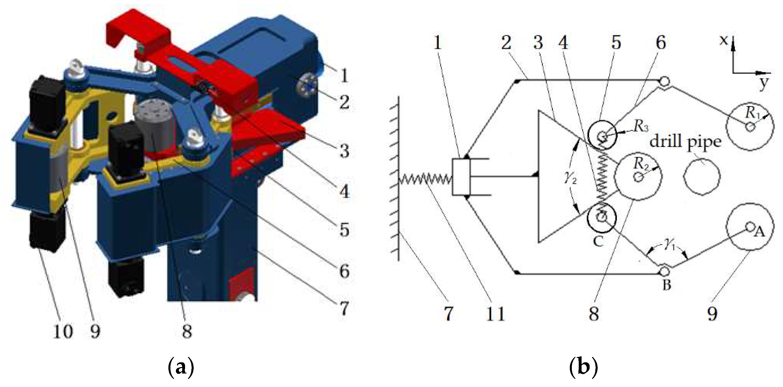
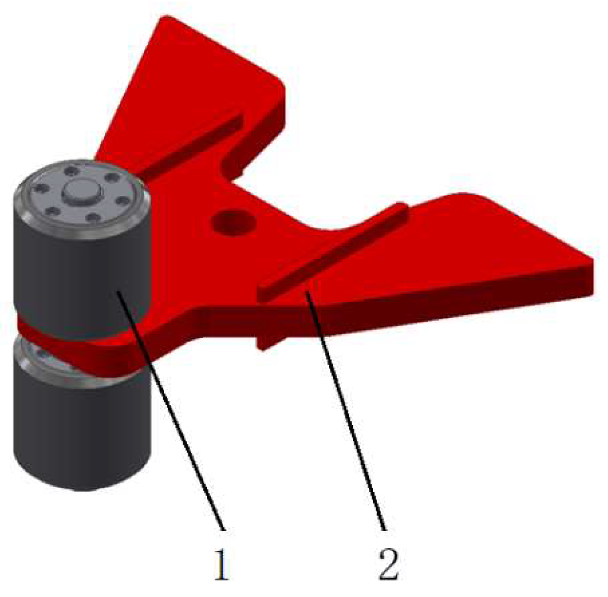
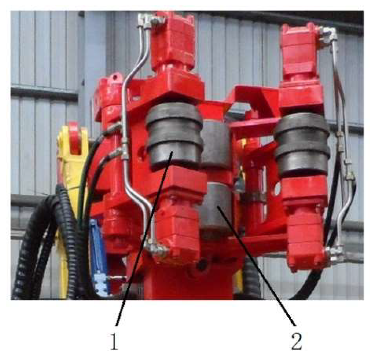
2.1. Structure and Working Principle of Spinner Mechanism

The working tong body of the iron roughneck includes two parts: the hydraulic main tong and the spinner mechanism. The hydraulic main tong is used to clamp the lower drill pipe and realize the punching action of the upper drill pipe, and the spinner mechanism is used to realize the rapid screwing-in or disengagement of the thread of the upper drill pipe [22]. When the spinner mechanism works, the lower drill pipe is clamped by the hydraulic main tong so that the central position of the drill pipe is determined. Ensuring the alignment between the upper drill pipe and the lower drill pipe is an important guarantee to realize the spinning action.
The spinner mechanism is shown in Figure 1: (a) is a three-dimensional model, and (b) is a kinematic diagram, which is mainly composed of a clamping oil cylinder, cross beam, wedge plate, return spring, tangent wheel, clamping arm, column, follow-up roller, driving roller, hydraulic motor, and floating mechanism. The main characteristic dimensions of the mechanism are as follows: the length of the clamping arm AB and BC are LAB = 332 mm, LBC = 320 mm, and the included angle is γ1 = 134°; the included angle between two sides of the wedge plate is γ2 = 60°; the radius R1 of the driving roller is equal to the radius R2 of the follow-up roller, which is R1 = R2 = Ra = 90 mm; the radius of the tangent wheel is R3 = 50 mm.
The spinner mechanism adopts the structure of three rollers, including two driving rollers driven by hydraulic motor and one follow-up roller. When it is working, the piston rod of the clamping oil cylinder extends to push the wedge plate to drive the follow-up roller to approach the drill pipe. At the same time, the two sides of the wedge plate push the tangent wheel installed at one end of the clamping arm to swing outward, and then drive the clamping arm to rotate around the middle pin shaft to realize the inward rotation of the driving roller installed at the other end of the clamping arm. This form of spinner mechanism reduces the number of clamping oil cylinders and has a compact structure. However, when working, the driving rollers and the following roller will not contact the drilling tool at the same time. To ensure that the three rollers can hold the drilling tool tightly, a floating mechanism is set between the cross beam and the column. When the roller in one direction contacts the drilling tool the contact force is generated. Due to the action of the floating mechanism, the whole spinner mechanism outside the column will move back or forth under the action of the force until the three spin-rollers completely clamp the drilling tool. When the three rollers hold the drilling tool tightly, the hydraulic motor drives the driving roller to rotate and thus drive the drilling tool to rotate clockwise or counterclockwise to complete the rapid screwing-in or screwing-out of the drilling tool thread. The return spring in the figure is used to ensure that the tangent wheel is always in contact with the edge of the wedge plate, and the two clamping arms can quickly release the drilling tool when the piston rod of the clamping cylinder retracts. The main technical parameters of the spinner mechanism are shown in Table 1.

2.2. Analysis of Position Deviation between the Spin-Roller and the Drilling Tool

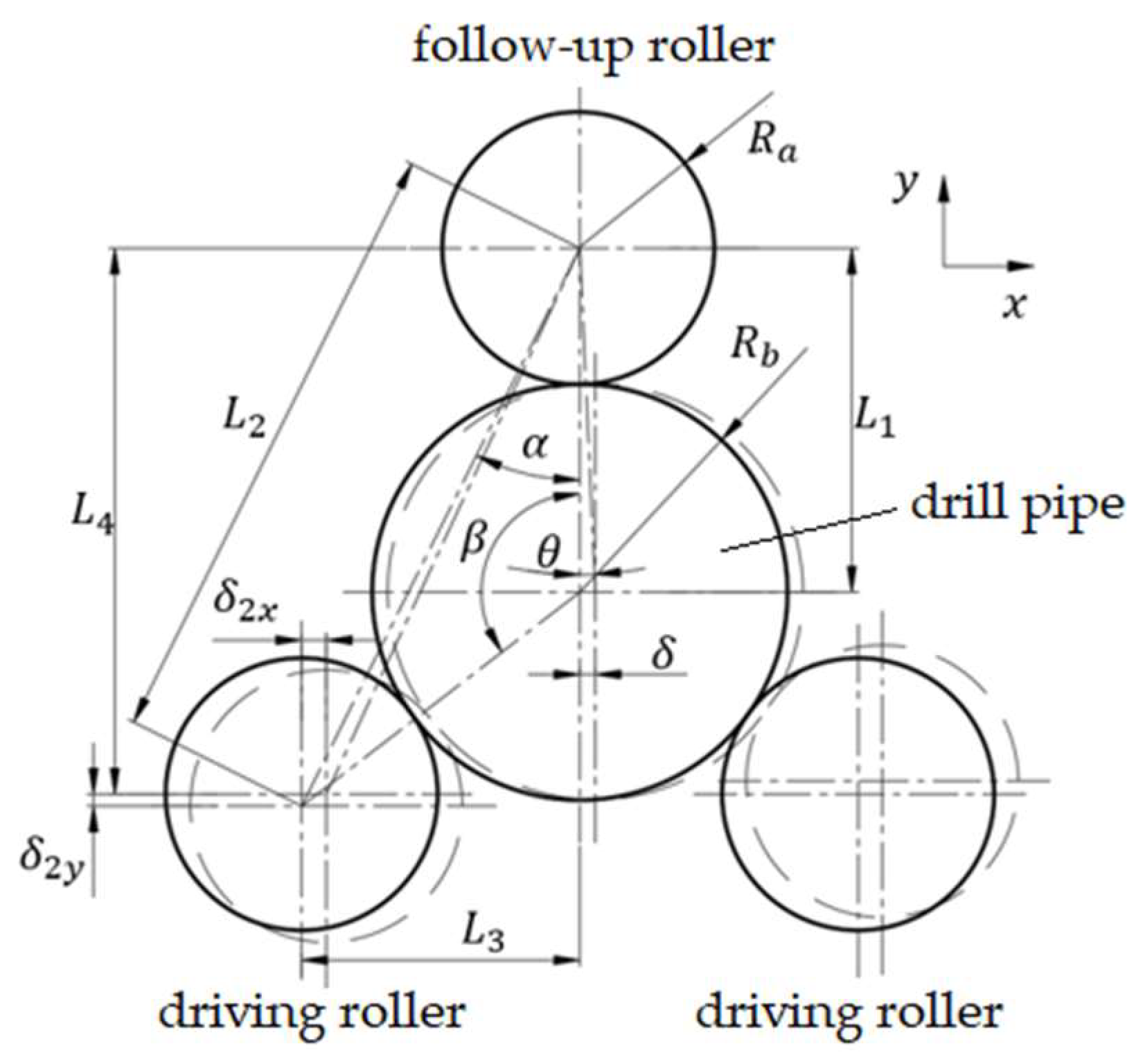
2.2.1. Analysis of Contact Mode between Spin-Rollers and Drilling Tool

It is evident from Figure 1 that when the wedge plate drives the clamping arm and the follower roller inward, two situations may result: one is that the driving roller contacts the drilling tool first, and the follow-up roller contacts the drilling tool later; second, the follow-up roller contacts the drilling tool first, and the driving roller contacts the drilling tool later. Due to the larger aspect ratio of the drill-pipe stand used in drilling, it is easy to cause a certain curvature of the drill pipe [23]. To realize the full contact between the spin-rollers and the drill pipe, a small range of swing freedom is often reserved in the spinner mechanism to adapt to the position deviation of the drill pipe.
The deviation of the drill pipe may occur in x direction (lateral direction), y direction (longitudinal direction), or both. For the deviation in y direction, since it is consistent with the direction of the force of the floating mechanism, it can be reduced or eliminated under the action of the clamping process of the spin-rollers or the dynamic load during spin; in addition, the deviation in the y direction can be reduced by adjusting the initial position of the cross beam. Therefore, for the spin mechanism with good floating performance, the conventional deviation in y direction will not have a negative impact on the working performance of the spinner mechanism. Whereas the deviation in the x direction will make the spinner mechanism have an eccentric load and affect the floating sensitivity of the floating mechanism. Therefore, the deviation in x direction has an obvious impact on the spin performance. The deviation of the drill pipe in x direction is mainly analyzed in this paper.
When the driving roller makes contact with the drill pipe first, due to the symmetrical arrangement of the two spin-rollers, the position of the drill pipe can be limited, and the spinner mechanism can maintain a good centering and holding capacity. When the follow-up roller makes contact with the drill pipe first, due to the axis deviation of the drill pipe, the impact force, and the approximate line of contact between the roller and drill pipe, it easily causes the drill pipe axis to offset to one side relative to the tong body. The deviation in this case is analyzed below.

2.2.2. Theoretical Analysis

Figure 2 is the analysis diagram of the deviation after the spin-rollers hold the drill pipe tightly. The circles drawn with solid lines in the figure represent the positions of the drill pipe and the roller when the axis is not offset, and the dashed circles represent the location of the when the axis is offset. If the eccentricity of the drill pipe and the roller is too large, the drill pipe and the iron roughneck will vibrate greatly during screwing, resulting in poor contact between the roller and the drill pipe, affecting the stability of screwing and possibly damaging the thread of the drill tool. The eccentricity relationship between driving rollers and drill pipe is analyzed as follows:
As shown in Figure 2, take the axis position of the follow-up roller as the fixed reference. Assuming that all three rollers are in contact with the drilling tool, the deviation of the drilling tool in the x direction is δ. Under the condition of no offset, the axial distance L1 between the follow-up roller and the drill pipe is:
L 1 = R a + R b
After the deviation occurs, set the included angle between the connecting line between the follow-up roller and the drill pipe axis and the y axis as θ, and then it is evident from the figure:
sin θ = δ R a + R b
So θ can be expressed as follows:
θ = arcsin δ R a + R b
After the offset, the drill pipe and the follow-up roller are still tangential to the outer surface, so the distance between the two axis lines along the y-axis direction is:
L 1 y = L 1 cos θ = ( R a + R b ) c o s θ
The deviation of the drill pipe in the y-axis direction δ1y is:
δ 1 y = | L 1 L 1 y | = | ( R a + R b ) ( 1 cos θ ) |
assuming the relative positions of the components of the spinner mechanism remain unchanged. When there is no offset, the center angle between the axis of the follow-up roller and the axis of the driving roller relative to the axis of the drill pipe is β. The included angle between the axis connecting line of the driving roller, the follow-up roller, and the y-axis is α. The axial distance between the follow-up roller and the driving roller is L2. The diameters of the driving roller and the follow-up roller are equal, so the axial distance between the follow-up roller and the drill pipe is also L1. According to the sine theorem, L2 and L1 meet the following relationship:
L 2 sin β = L 1 sin α
where α and β meet the following relationship:
α = π β 2
Therefore, the expression of L2 can be obtained as follows:
L 2 = sin β L 1 sin α = sin β R a + R b sin ( π β 2 )
Without offset, the distance between the driving roller and the follow-up roller in the x-axis direction is:
L 3 = L 2 sin α
When offset occurs, the distance becomes as follows:
L 3 = L 2 sin ( α θ )
So, the deviation in the x-axis direction compared with no offset is:
δ 2 x = | L 3 L 3 | = | L 2 [ sin α sin ( α θ ) ] |
Without offset, the distance between the axis of the driving roller and the axis of the follow-up roller on the y-axis is:
L 4 = L 2 cos α
When offset occurs, the axial distance in the y-axis direction is as follows:
L 4 = L 2 cos ( α θ )
The deviation in the y-axis direction of the roller is obtained as follows:
δ 2 y = | L 4 L 4 | = | L 2 [ cos α cos ( α θ ) ] |
According to the above analysis, the position offset of the drill pipe axis relative to the follow-up roller will also offset the driving roller. It is evident from the deviation formula that the deviation of the driving roller is related to the deviation δ of drill pipe, the diameter of drill pipe, and the center angle formed during clamping. These deviations may gradually correct when the spinner mechanism holds the drill pipe tightly, but they may also make the spinner mechanism deflect and vibrate in the screwing process, which is not conducive to the overall stability of the iron roughneck.

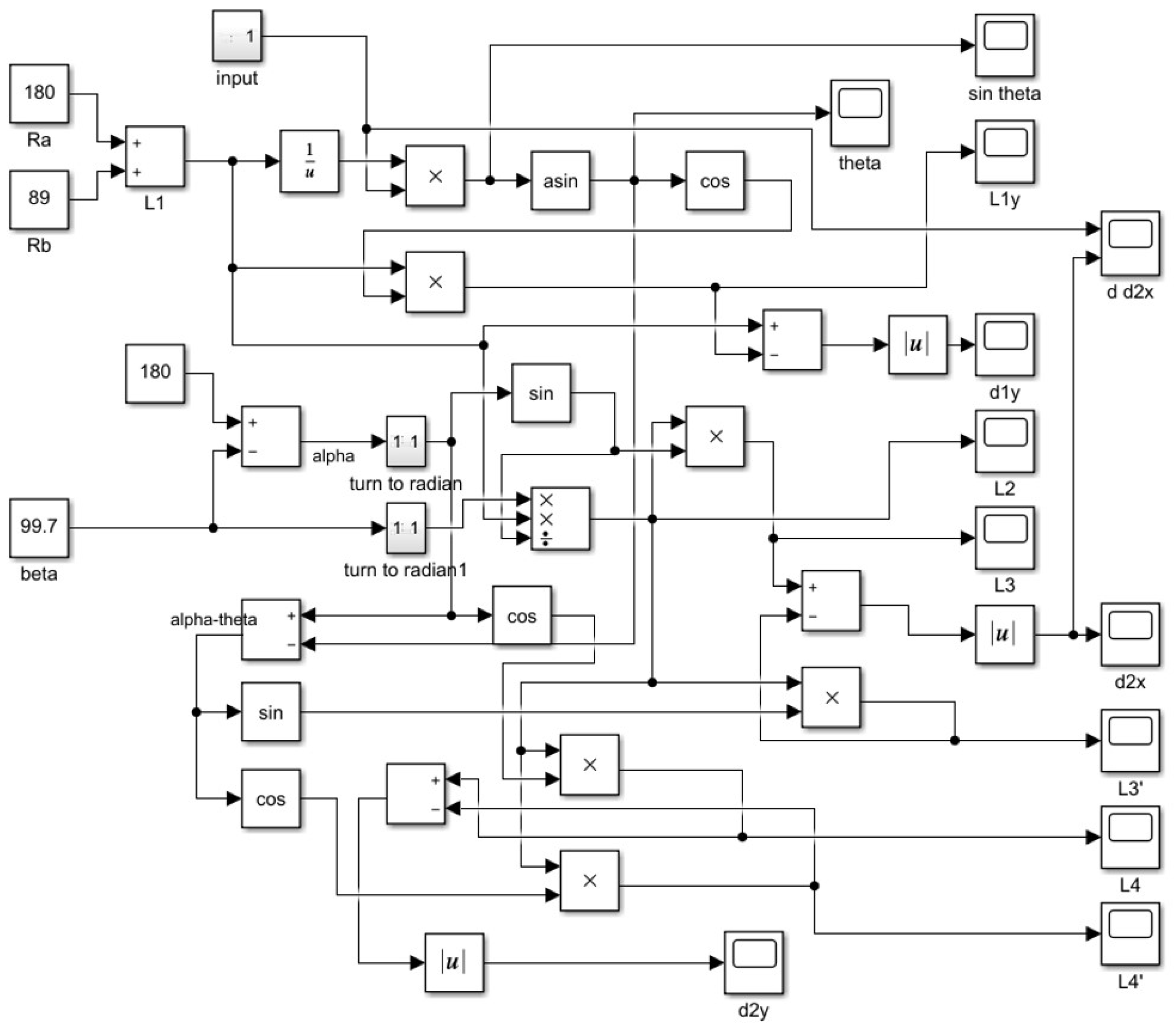
2.2.3. Simulation Solution

According to the relationship obtained from the above analysis, the Simulink module of MATLAB software can be used to solve it. Establish the model corresponding to the above mathematical relationship in Simulink software, as shown in Figure 3. By inputting the parameter values of each known mechanism into the model, the values of δ1y, δ2x, and δ2y corresponding to different deviations δ can be obtained.
The diameters of the driving rollers and the follow-up roller of the spinner mechanism are all 180 mm, and the diameters of the drilling tool are taken as 89 mm, 168 mm, and 311 mm. According to the geometric relationship, when the spinner mechanism holds different drilling tools, the corresponding angle β’s shown in Table 2.
In the Simulink model, the deviation δ is set as a variable gradually increasing within 0 to 10 mm, and the drilling tool diameters are set as 311 mm, 168 mm, and 89 mm. According to the angle β in Table 2, the value of δ1y, δ2x, and δ2y corresponding to different deviations δ can be obtained, and the obtained data are draw into curves as shown in Figure 4.
According to the deviation relation curve, with the increase of the deviation δ of the drilling tool, the deviation of the driving roller in the x-axis and y-axis direction δ2x and δ2y increases linearly, and the increase of δ2y is more obvious. With the increase of the drilling tool´s diameter, the deviation also increases. When the drilling tool´s diameter is 89 mm and the drilling tool deviation δ is 10 mm, the deviation of the driving roller δ2x and δ2y is 3 mm and 17 mm, respectively. When the drilling tool´s diameter is 168 mm, the corresponding δ2x and δ2y is 8 mm and 19 mm, respectively. When the drilling tool´s diameter is 311 mm, the corresponding δ2x and δ2y reaches 12 mm and 20 mm, respectively. However, the deviations δ1y of the drilling tool in the y direction in the three cases are relatively small, indicating that the offset of the drilling tool mainly occurs in the x-axis direction under the restriction of the spin-roller. When the drilling tool is offset, the deviation of the driving roller δ2y is significantly greater than the drilling tool deviation δ. In practice, it often occurs that drilling tool´s offset δ is more than 10 mm, and its impact cannot be ignored. Excessive deviation will further aggravate the deflection amplitude of drilling tool and spin-rollers in the process of screwing, affect the contact between roller and drilling tool, the stability of action, and then affect the spinning efficiency. In addition, it is easy to aggravate the wear of spin-rollers and the damage of drilling tool´s thread. Therefore, it is necessary to control the deviation of drilling tools and spin-rollers to ensure the stability and reliability of spinning action.

2.3. Method of Reducing Lateral Position Deviation

According to the above analysis, when limiting the deviation δ of the drilling tool, the deviation of the driving rollers can be effectively reduced. Therefore, the structural form of the follow-up roller of the spinner mechanism is improved. The single follow-up roller in Figure 3 is replaced by symmetrically arranged double follow-up rollers, as shown in Figure 5.
Figure 5 is a schematic diagram of the contact process between the improved follow-up roller and the drill pipe. The left figure shows the state of deviation at the moment of contact between the roller and the drill pipe, and the right figure shows the state of the drill pipe returning to the middle position after clamping. The specific process is as follows: When the drill pipe axis displays the deviation δ shown in the left figure of Figure 5, there will be only one side of the follow-up rollers in contact with the drill pipe. If the driving roller also contacts the drill pipe at the same time, only one side of the driving rollers contacts the drill pipe, which is shown in the figure. According to the force analysis of the drill pipe, the directions of the force F of the follow-up roller and the force F′ of the driving roller point to the axis of the drill pipe along their respective radial directions. The x direction components of these two forces will make the drill pipe move in the direction of reducing the offset. With the further application of the clamping force, the drill pipe will return to the position of the symmetrical central plane defined by the spin-rollers, so as to eliminate the position deviation in the x direction, as shown in the right figure of Figure 5.

2.4. Experimental Research

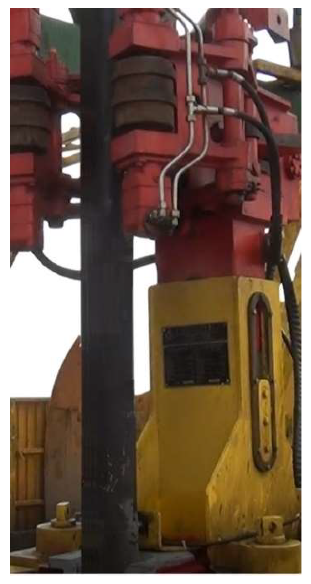
2.4.1. Experimental Equipment

To verify the influence of the deviation of the drill pipe in different directions on the working performance of the spinner mechanism, experiments were carried out on two kinds of spinner mechanisms with different arrangements of follow-up rollers
1.
Spinner mechanism with single follow-up roller:
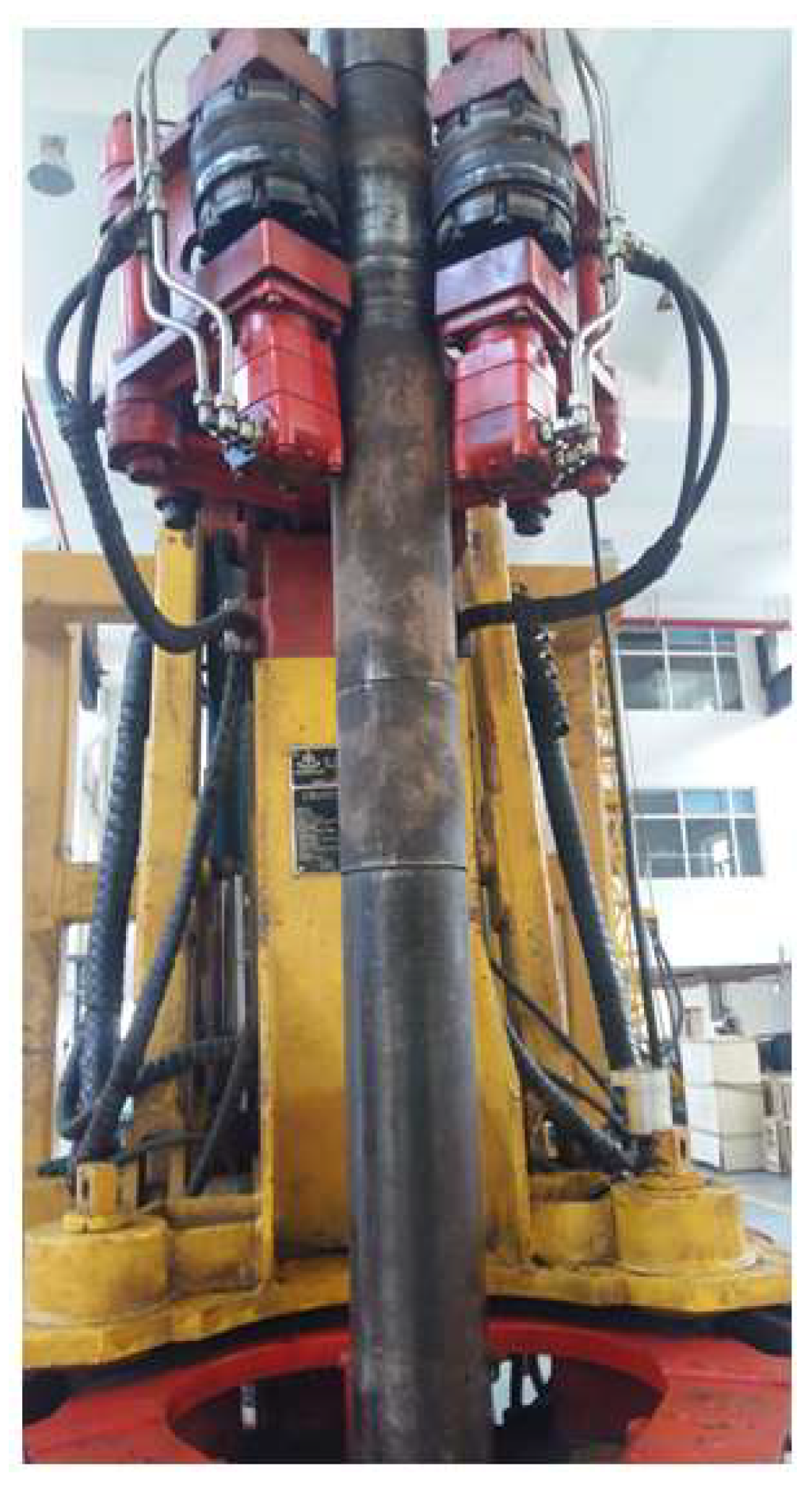
In the first form, a single follow-up roller is used, which is directly installed on the wedge plate, as shown in Figure 6, and the physical photo of the spinner mechanism using a single follow-up roller is shown in Figure 7.
2.
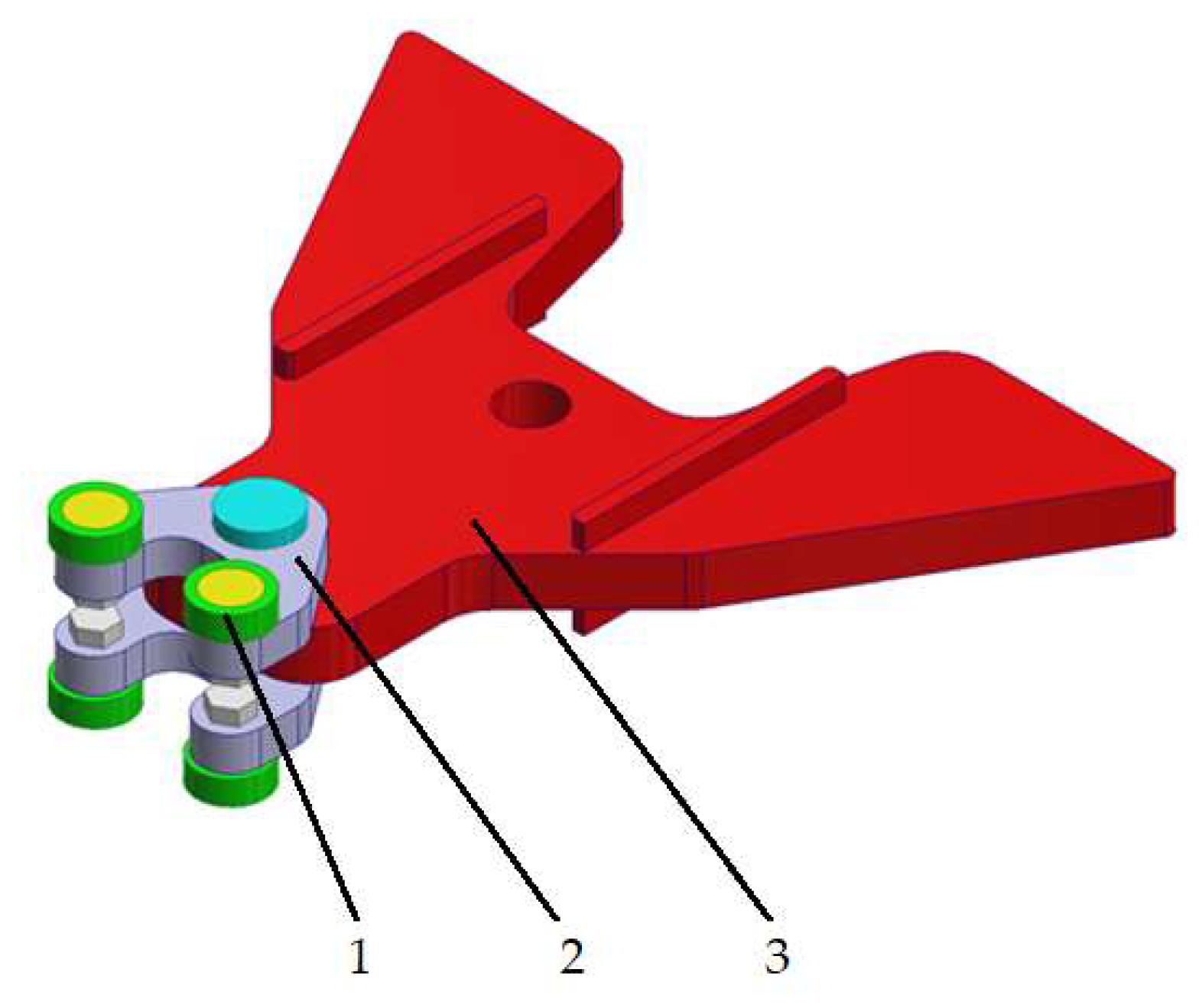
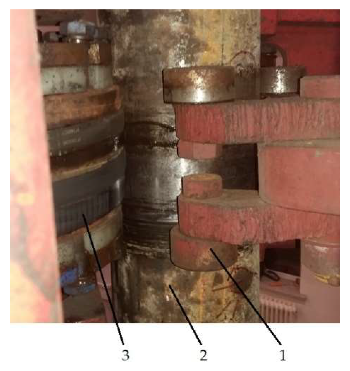
Spinner mechanism with double follow-up rollers:
In the second form, double follow-up rollers are symmetrically arranged, and the follow-up rollers are installed on the wedge plate through the roller bracket, as shown in Figure 8. Figure 9 is a photo of the spin-rollers holding the drill pipe tightly, and the driving roller is replaced with a combined roller, which further increases the friction and is convenient for disassembly and replacement. It is evident from the figure that each roller is in good contact with the drill pipe.

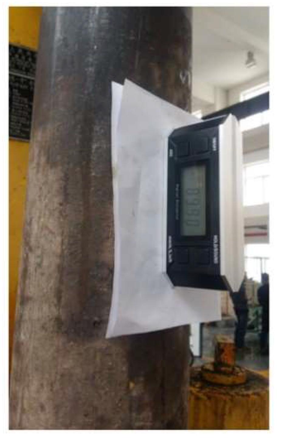
2.4.2. Experimental Method

1.
Experiment involving the spinner mechanism with a single follow-up roller:
To verify the influence of the drill pipe’s position deviation in different directions and sizes on the working performance of the spinner mechanism, the initial position of the spinner mechanism was appropriately adjusted in the experiment to obtain the drill pipe’s position deviation at different sizes. After the spin-rollers hold the drill pipe tightly, use the magnetic suction digital protractor to test the inclination of the drill pipe; the technical parameters of the digital protractor are shown in Table 3. The outer diameter of the drill pipe used in the test is 168 mm, and the length of the upper drill pipe used for spin is 2300 mm; the distance between the fixed position of the lower drill pipe and the spin-rollers is 2017 mm, and the protractor is stuck onto the surface of the drill pipe between this distance. Repeated holding tests are carried out to test the inclination of the drill pipe in the x and y directions (the direction of coordinate axis is shown in Figure 5), and then the spin experiment is carried out to observe the spin action state.
2.
Experiment involving the spinner mechanism with double follow-up rollers:
The experimental method of the spinner mechanism with double follow-up rollers is basically the same as that of the single follow-up roller. The main difference is that after the initial position of the spinner mechanism is adjusted, it will not be changed in the subsequent repeated experiments.
The photos of the experiments involving the spinner mechanism with the single follow-up roller and the spinner mechanism with the double follow-up rollers are shown as Figure 10 and Figure 11, respectively, and the inclination angle test photo is shown as Figure 12.

3. Results and Discussion

According to the measurement results and structural dimensions, the deflection angle of the drill pipe relative to the vertical axis and the dimensional deviation at the position of the spin-rollers can be obtained. The measurement and experimental results of the two types of spinner mechanism are as follows.

3.1. Experimental Results of the Spinner Mechanism with Single Follow-Up Roller

The experimental results of the spinner mechanism with a single follow-up roller are shown in Table 4. The data in the table are representative data selected from many tests, covering the maximum and minimum position deviations of the drill pipe in x direction and several different position deviations in the y direction. It is evident from the test data that the position deviation of the drill pipe in the x direction ranges from 3.52 mm to 10.56 mm.
When the position deviation of the drill pipe in the x direction is 3.52 mm and the deviation in the y direction is different, the spin action is completed differently. When the deviation in the y direction is 19.36 mm, the spin action is very unstable, and the rollers have poor contact with the drill pipe, resulting in obvious vibration and slipping, which affects the spin action. When the deviation in the y direction is 12.32 mm, 8.80 mm, or 5.28 mm, the spin action is smooth, the vibration is small, and there is no obvious slipping. It is evident from the experimental results that when the position deviation in the x direction is small, only when the deviation in the y direction reaches a certain value will the spin effect be seriously affected. In other cases, the spinner mechanism is in good working condition.
When the position deviation of the drill pipe in the x direction is 7.04 mm, and the deviation in the y direction is 3.52 mm or 5.28 mm, the spinner mechanism can complete the spin operation, but there will be a certain degree of vibration and slipping during the working process, which will affect the spin efficiency.
When the position deviation of the drill pipe in the x direction is 10.56 mm, and the deviation in the y direction is 3.52 mm or 5.28 mm, the contact between the rollers and the drill pipe is poor, resulting in greater vibration and slipping, which affects the spin action and may even render the mechanism incapable of spinning normally.
From the above experimental results, it is evident that the position deviation of the drill pipe in the x direction has a great influence on the operation of the spinner mechanism, while the position deviation in the y direction has a relatively small influence. When the position deviation in the x direction of the drill pipe is small, the spinner mechanism can work normally within a certain range of position deviation in the y direction. However, as the position deviation in the x direction increases gradually, even if the position deviation in the y direction is small, the operation of the spinner mechanism will be seriously affected.
This situation can be analyzed by combining the deviation relation curve between the driving rollers and the drill pipe in Figure 4c: (1) When the position deviation in the x direction of the drill pipe is 3.52 mm, it is evident from Figure 4c that the position deviations in the x and y directions of the driving roller are 2.82 mm and 6.79 mm, respectively. The offset is small, and the center position of the spin action can be guaranteed, so the spin action is relatively stable; (2) When the position deviation in the x direction of the drill pipe is 7.04 mm, the position deviations in the x and y directions of the driving roller are 5.63 mm and 13.59 mm respectively, which have a certain offset. During spinning, the contact conditions and forces between each roller and drilling pipe will be unbalanced, so small vibrations and slips occur; (3) When the position deviation in the x direction of the drill pipe is 10.56 mm, the position deviations in the x and y directions of the driving roller are 8.45 mm and 20.38 mm respectively. In this case, the deflection of the driving roller is large and obvious, which results in a certain degree of deflection when spinning. The rollers cannot fully contact the drilling pipe and cannot guarantee the effective spinning action.

3.2. Experimental Results of the Spinner Mechanism with Double Follow-Up Rollers

The experimental results of the spinner mechanism with double follow-up rollers are shown in Table 5. The data in the table are the results of several consecutive tests after the position of the spinner mechanism has been set. It is evident from the test data that the position deviation of the drill pipe in the x direction is zero in most cases and 1.76 mm in a few cases, which is very small. Considering the size and distribution of the deviations, it can be surmised that the drill pipe basically does not deviate in the x direction, indicating that the improved roller structure limits the position deviation in the x direction. It is evident from the table that the inclination angle in the y direction ranges from 89.80° to 89.90°, the deviation angle from the vertical axis is 0.10° to 0.20°, and the dimensional deviation of the drill pipe in the y direction is between 3.52 mm and 7.04 mm at the position of the spin-rollers. The operation results show that under these conditions, the spinner mechanism works relatively stably, and the spin action is completed smoothly.
For the spinner mechanism with double follow-up rollers, there is no deflection of the spin-rollers since the position deviation in the x direction is limited. Whereas the deviation in the y direction is small, and the direction of the deviation is consistent with the floating direction of the mechanism. The deviation can be easily corrected in the process of spin, which ensures the centering performance of the drill pipe and its working stability.

4. Conclusions

The position deviation between the iron roughneck’s spin-rollers and the drilling tool was studied in this paper, and the following conclusions are drawn:
(1)
The position deviation of the drilling tool in the x direction (lateral direction) is the main factor affecting the working performance of the spinner mechanism and reducing the position deviation in this direction can effectively improve the spin performance.
(2)
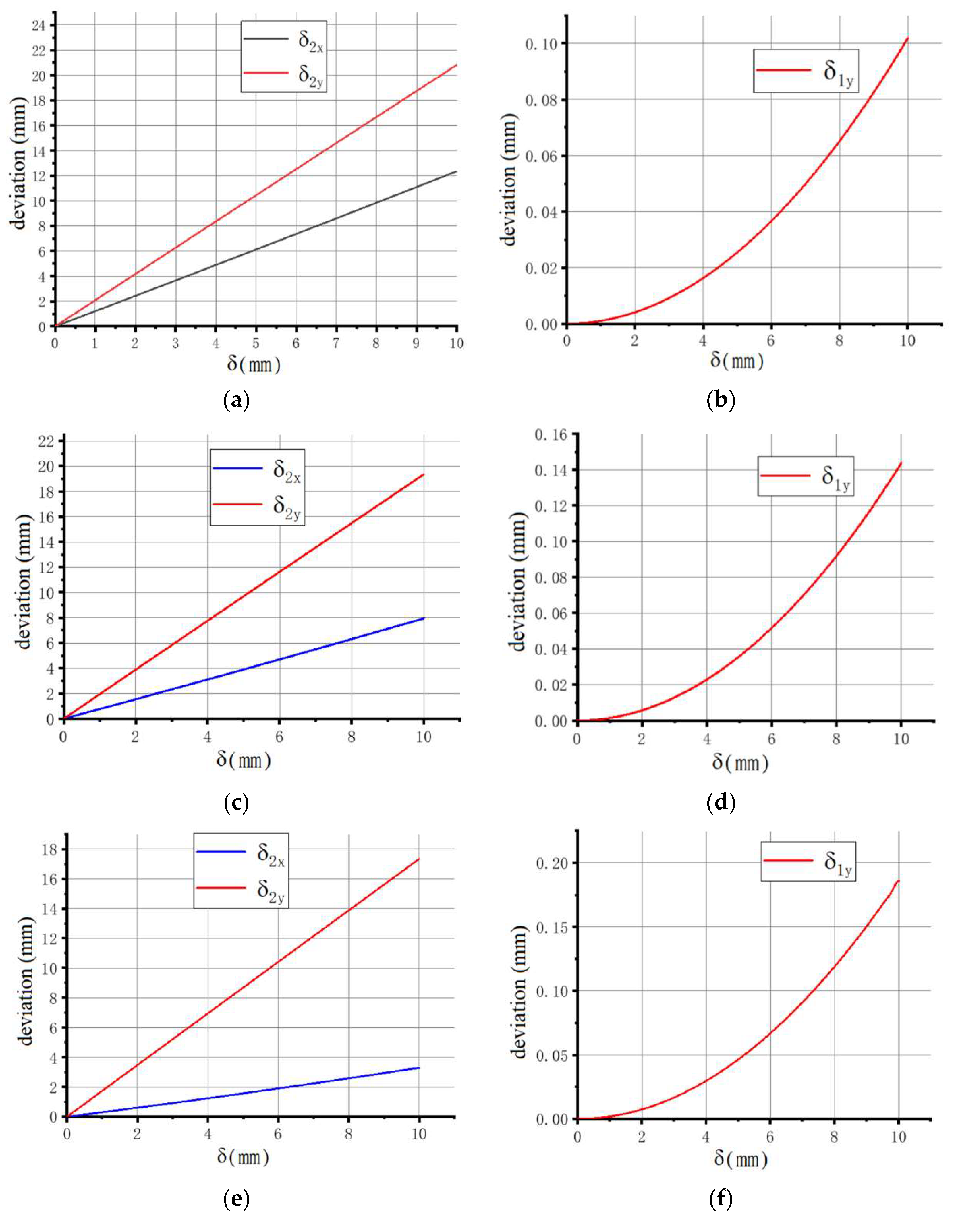
If using the spinner mechanism with three spin-rollers, when a single follow-up roller contacts the drill pipe first, the deviation in the x direction of the drill pipe axis can easily occur. With the increase of the deviation of the drill pipe axis, the deviation of the driving roller axis in the x direction and y direction also increases gradually, and the deviation of the driving roller axis along the y-axis direction is significantly greater than that of the drill pipe axis.
(3)
Within the effective working range of the spinner mechanism, the larger the diameter of the drill pipe, the greater the deviation of the axis of the driving roller. The larger deviation directly affects the stability of the screwing action and the screwing effect.
(4)
The deviation of the drill pipe and the spin-rollers can be reduced by replacing a single follow-up roller with a symmetrically arranged double follow-up roller, thus ensuring the centering performance and realizing reliable screwing action. In this example, the drill pipe has no position deviation in the x direction, and the position deviation in the y direction is between 3.52~7.04 mm, which meets the working requirements of the spinner mechanism.
This paper’s research provides a theoretical and methodological reference for reducing the position deviation of drilling tool axes. In addition, good machining accuracy and mechanism floating performance are also important links to eliminate or reduce axis deviation. The limitation of this paper is that the length of the drill pipe or the drill pipe stand used in different constructions is different, but the length of the drill pipe used in this experiment is relatively short, which will be different from the deviation size and working state in actual construction. However, the research results reflect the influence law of different deviations on the spin operation and are suitable for application to similar mechanisms.

Author Contributions

Conceptualization, Y.S. and Q.L.; methodology, Y.S. and Q.L.; software, Y.S. and Q.L.; validation, Y.S., Q.L. and X.Z.; formal analysis, Y.S. and X.Z.; investigation, Y.S. and Q.L.; resources, Y.S., Q.L. and X.Z.; data curation, Y.S. and Q.L.; writing—original draft preparation, Y.S.; writing—review and editing, Y.S., Q.L. and X.Z.; visualization, Q.L.; supervision, Y.S.; project administration, Y.S.; funding acquisition, Y.S. All authors have read and agreed to the published version of the manuscript.

Funding

This research was funded by the Ministry of Land and Resources of China, grant number SinoProbe-09-05; China Geological Survey, grant number 12120113017600; and Program for JLU Science and Technology Innovative Research Team, grant number 2017TD-13.

Institutional Review Board Statement

Not applicable.

Informed Consent Statement

Not applicable.

Data Availability Statement

The data present in this study are available on request from the corresponding author.

Conflicts of Interest

The authors declare no conflict of interest.

References

  1. Ramba, V.; Selvaraju, S.; Subbiah, S.; Palanisamy, M.; Srivastava, A. Optimization of drilling parameters using improved play-back methodology. J. Pet. Sci. Eng. 2021, 206, 108991. [Google Scholar] [CrossRef]
  2. Godhavn, J.M.; Pavlov, A.; Kaasa, G.O.; Rolland, N.L. Drilling seeking automatic control solutions. In Proceedings of the 18th IFAC World Congress (IFAC’11), Milano, Italy, 28 August–2 September 2011. [Google Scholar] [CrossRef]
  3. Sun, Y.H.; Zhang, F.Y.; Wang, Q.Y.; Gao, K. Application of “Crust 1” 10k ultra-deep scientific drilling rig in Songliao Basin Drilling Project (CCSD-SKII). J. Pet. Sci. Eng. 2016, 145, 222–229. [Google Scholar] [CrossRef]
  4. Zhdaneev, O.V.; Frolov, K.N.; Petrakov, Y.A. Predictive Systems for the Well Drilling Operations. In Cyber-Physical Systems: Design and Application for Industry 4.0. Studies in Systems, Decision and Control; Springer: Berlin/Heidelberg, Germany, 2021; Volume 342, pp. 347–368. [Google Scholar] [CrossRef]
  5. Yan, W.H.; Xie, D.; Guo, L.T.; Zhao, L.G.; Peng, Y.; Hu, N. Design and Analysis of Iron Roughneck Non-Clamp-Tooth Clamping Mechanism. In Proceedings of the 2020 International Conference on Advanced Materials and Intelligent Manufacturing & Advanced Steel for Automotive Seminar, Guilin, China, 21–23 August 2020. [Google Scholar] [CrossRef]
  6. Yu, J. Mechanical Analysis of the Structure and Roll of Iron Roughneck Screw Clamp. Master’s Thesis, Xi’an Shiyou University, Xi’an, China, 6 June 2020. [Google Scholar] [CrossRef]
  7. Shah, D.B.; Patel, K.M.; Trivedi, R.D. Analyzing Hertzian contact stress developed in a double row spherical roller bearing and its effect on fatigue life. Ind. Lubr. Tribol. 2016, 68, 361–368. [Google Scholar] [CrossRef]
  8. Hu, Z.J.; Ma, Q.F.; Liu, J.L. Load Analysis and Calculation of Makeup and Breakout Device on Continuous Circulation System. China Pet. Mach. 2019, 47, 31–37. [Google Scholar] [CrossRef]
  9. Jing, Z.J.; Xu, X.P.; Nan, S.Q.; Fan, X.Z. Optimization and Testing of the Carbon Fiber Roller in an Iron Roughneck’s Spinner. Mech. Eng. 2021, 3, 75–78. [Google Scholar]
  10. Deng, C.Y. Design and Analysis of Telescopic Boom Type Drilling Rig Based on Drilling Platform. Master’s Thesis, Dalian University of Technology, Dalian, China, 4 June 2018. [Google Scholar]
  11. Zhu, J.J.; Dang, E.; Wu, Z.X.; Liu, Y.F. An experimental study of bainite steel for iron roughneck roller. China Pet. Mach. 2011, 39, 16–18. [Google Scholar] [CrossRef]
  12. Mao, L.J.; Cai, M.J.; Wang, G.R. Effect of rotation speed on the abrasive–erosive–corrosive wear of steel pipes against steel casings used in drilling for petroleum. Wear 2018, 410–411, 1–10. [Google Scholar] [CrossRef]
  13. Liang, S.A.; Li, W.D.; Zhang, Q.; Li, H.B.; Li, A.L. Design and Application of Fault Diagnosis System for Iron Roughneck. Hy-Draulics Pneum. Seals 2020, 40, 81–85. [Google Scholar] [CrossRef]
  14. Yu, P.; Mu, T.; Zhu, L.H.; Zhou, Z.Y.; Song, J. Nonlinear dynamic analysis and stability control of drilling tool conveying mechanism. J. Jilin Univ. (Eng. Technol. Ed.) 2021, 51, 820–830. [Google Scholar] [CrossRef]
  15. Zheng, X.H.; Wang, Q.Y.; Sheng, J.; Zhong, W.L. Analysis of automatic positioning process of HIR-90 fully hydraulic Iron Roughneck. World Geol. 2022, 41, 1–11. [Google Scholar]
  16. Xu, X.T. Design and Analysis of New-Type Iron Roughneck. Master’s Thesis, Dalian University of Technology, Dalian, China, 28 April 2018. [Google Scholar]
  17. Xu, M. Research on Adaptive Technology of Spinner of Iron Roughneck. Master’s Thesis, Jilin University, Changchun, China, May 2018. [Google Scholar]
  18. Liu, W.; Zhu, X.L.; Ding, J.; Liu, Y.Z. The study on automatically detecting the center of iron roughneck based on photoelectric sensor. Mach. Des. Manuf. Eng. 2015, 44, 66–69. [Google Scholar] [CrossRef]
  19. Zhang, H.S.; Gu, M.Y.; Li, X.R. Design of Control System for Iron Roughneck based on Vision. New Technol. New Process 2010, 1, 23–25. [Google Scholar]
  20. Khare, S.K. Machine vision for drill string slip status detection. Pet. Res. 2022, 7, 115–122. [Google Scholar] [CrossRef]
  21. Abimbola, M.; Khan, F. Development of an integrated tool for risk analysis of drilling operations. Process Saf. Environ. Prot. 2016, 102, 421–430. [Google Scholar] [CrossRef]
  22. Liu, J.; Wen, Y.Q. Analysis of the Control Strategy of the Intelligent Iron Roughneck’s Make-up and Break-out Fusion with Fuzzy Adaptive Control Algorithm. J. Phys. Conf. Ser. 2021, 1992, 032099. [Google Scholar] [CrossRef]
  23. Zhang, D.H.; Wang, C.R. Technology Status and Development Trend of Intelligent Drilling Rigs. China Pet. Mach. 2020, 48, 30–36. [Google Scholar] [CrossRef]
Figure 1. Spinner mechanism: (a) three-dimensional model; (b) kinematic diagram. In the figure: 1—clamping oil cylinder; 2—cross beam; 3—wedge plate; 4—return spring; 5—tangent wheel; 6—clamping arm; 7—column; 8—follow-up roller; 9—driving roller; 10—hydraulic motor; 11—floating mechanism.
Applsci 12 05827 g001
Figure 2. Diagram of deviation analysis.
Applsci 12 05827 g002
Figure 3. Simulink solving relational model.
Applsci 12 05827 g003
Figure 4. Deviation relation curve: (a) driving roller deviation (clamping 311 drilling tool); (b) drilling tool deviation (clamping 311 drilling tool); (c) driving roller deviation (clamping 168 drilling tool); (d) drilling tool deviation (clamping 168 drilling tool); (e) driving roller deviation (clamping 89 drilling tool); (f) drilling tool deviation (clamping 89 drilling tool).
Applsci 12 05827 g004
Figure 5. Schematic diagram of eccentric to tight state.
Applsci 12 05827 g005
Figure 6. Single follow-up roller installed on the wedge plate. In the figure: 1—roller, 2—wedge plate.
Applsci 12 05827 g006
Figure 7. Spinner mechanism with single follow-up roller. In the figure: 1—driving roller, 2—follow-up roller.
Applsci 12 05827 g007
Figure 8. Follow-up rollers installed on the wedge plate. In the figure: 1—roller, 2—bracket, 3—wedge plate.
Applsci 12 05827 g008
Figure 9. Physical photo. In the figure: 1—follow-up roller, 2—drill pipe, 3—driving roller.
Applsci 12 05827 g009
Figure 10. Experiment involving the spinner mechanism with single follow-up roller.
Applsci 12 05827 g010
Figure 11. Experiment involving the spinner mechanism with double follow-up rollers.
Applsci 12 05827 g011
Figure 12. Inclination test.
Applsci 12 05827 g012
Table 1. Technical parameters of the spinner mechanism.
Tubular Connection od RangeRated Pressure of Hydraulic SystemSpin SpeedSpin Torque
89~311 mm25 MPa100 rpm2373 Nm
Table 2. Angle β corresponding to different diameters.
Drilling Tool Diameter (mm)89168311
β (°)99.7111.5120.1
Table 3. Technical parameters of magnetic suction digital protractor.
ModelAccuracyResolutionRangeRepeatability
DIL-30 and 90° ≤ 0.10°
Other degree ≤ 0.15°
≤0.05°4 × 90° (0~360°)≤0.10°
Table 4. Position deviation of the drill pipe and spin condition of the spinner mechanism with single follow-up roller.
Drill Pipe Inclination
Angle (°)
Drill Pipe
Deviation Angle (°)
Dimensional Deviation (mm)Working Condition of
Spinner Mechanism
x Directiony Directionx Directiony Directionx Directiony Direction
89.9089.450.100.553.5219.36Unstable 1
89.9089.650.100.353.5212.32Good 2
89.9089.750.100.253.528.80Good
89.9089.850.100.153.525.28Good
89.8089.900.200.107.043.52Average 3
89.8089.850.200.157.045.28Average
89.7089.900.300.1010.563.52Unstable
89.7089.850.300.1510.565.28Unstable
1 “Unstable” refers to the poor contact between the spinning roller and the drilling tool during operation, and the vibration is large. 2 “Good” refers to good operation without obvious slipping. 3 “Average” refers to the capacity for the spin operation to be completed, but that a certain amplitude of vibration and slipping may also occur.
Table 5. Position deviation of the drill pipe and spin condition of the spinner mechanism with double follow-up rollers.
Drill Pipe Inclination
Angle (°)
Drill Pipe
Deviation Angle (°)
Dimensional Deviation (mm)Working Condition of
Spinner Mechanism
x Directiony Directionx Directiony Directionx Directiony Direction
90.0089.9000.1003.52Good
90.0089.8500.1505.28Good
89.9589.800.050.201.767.04Good
90.0089.8500.1505.28Good
89.9589.800.050.201.767.04Good
90.0089.8500.1505.28Good
Publisher’s Note: MDPI stays neutral with regard to jurisdictional claims in published maps and institutional affiliations.

