Article

A Set of Novel Procedures for Carbon Fiber Reinforcement on Complex Curved Surfaces Using Multi Axis Additive Manufacturing

Institute for Airplane Production Technology, Hamburg University of Technology, 21073 Hamburg, Germany
*
Author to whom correspondence should be addressed.
Appl. Sci. 2022, 12(12), 5819; https://doi.org/10.3390/app12125819
Submission received: 9 May 2022 / Revised: 31 May 2022 / Accepted: 4 June 2022 / Published: 8 June 2022
(This article belongs to the Special Issue Recent Trends on the Mechanical Properties of Additive Manufacturing)

Abstract

:
There has been considerable research in recent years on the additive manufacturing (AM) of carbon fiber reinforced polymer (CFRP) parts based on the process of fused deposition modeling (FDM). The currently-applied steps within the manufacturing pipeline, such as slicing and path planning, consider only the planar case of filament deposition and mostly make no use of the possibility to place single pre-impregnated (prepreg) filaments. Classical methods such as tape-laying and laminating struggle with highly curved and complex geometries and require the costly production of molds, whereas when using AM, these geometries can be realized more easily and molds can be created using the same process. In this paper, a set of algorithms is presented that aims to resolve these problems. Criteria are formulated which enable the goal oriented development and evaluation of the presented methods and represent metrics for future methods. The developed algorithms enable the use of both continuous and discontinuous fiber patches in a much wider range of applications in designing and manufacturing of CFRPs. This opens up new possibilities in this promising field. The developed metrics and infrastructure further constitute progress in the field of multi-axis non-planar path planning for slicing algorithms in general and the conducted evaluation proves the formal applicability of the developed algorithms.

1. Introduction

Fused deposition modeling (FDM) as a form of 3D printing is the process of constructing a part by extruding a material through a nozzle, fusing extruded filament to the existing structure. Carbon fiber reinforced polymers (CFRPs) are composite materials achieving high strength-to-weight ratios and have seen increased application in the industry in domains such as aerospace, automotive and many others [1].
The process of being able to combine the benefits of FDM and CFRP has been a highly active topic in research over the last few years [1,2]. Dickson et al. state that the reason for this is the potential for CFRPs to match or exceed the mechanical performance of conventional composites [3]. With the development of a pre-impregnated (prepreg) fiber filament by the Markforged company and others, the possibility for printing carbon fiber was further enabled. A lot of research has gone into the evaluation of material properties [3,4], optimization of the printing process [5], printing hardware [2] and some investigations have been made into waste recycling [6,7]. Currently, a major bottleneck is the fact that classical 3D-Slicers lack adapted path planning methods [8,9]. Some publications have proposed planar strategies for utilizing carbon fibers effectively and industrial software exists only for some specific planar application scenarios [1].
Most of the methods currently used for manufacturing carbon fiber parts use molds where either sheets of carbon fiber cloth are layered or tape is placed onto the mold by use of industrial robots. These methods can achieve good mechanical properties but struggle with highly curved parts or complex geometries as buckling or problems in draping can be observed. The use of FDM allows the guided placement of single lines of the pre-impregnated filament, eliminates the need for expensive molds to be manufactured and enables the use of more complex parts with higher curvatures.
As well as exhibiting the drawbacks of planar algorithms in general [10], planar algorithms struggle to achieve good mechanical properties and high compliance with load cases [8]. This leads to the use of multi-axis printers being proposed for manufacturing CFRP parts with FDM [11]. A major limiting factor is the lack of software to enable the path planning for printing [8].
This paper aims to start the process of offering a toolbox of algorithms for creating new ways to construct and create fiber reinforcements on free-form surfaces. The structure of the paper is as follows: In the next sections prior works will be discussed, and our method will be presented. Section 2 gives an overview and explanation of the employed methods and developed evaluation criteria. In Section 3, the proposed algorithms are described and explained. In Section 4 and Section 5, the evaluation of the algorithms as well as the discussion of the results and the conclusion can be found.

1.1. Prior Work

The active field of research in CFRPs and FDM has resulted in a plethora of publications regarding this topic which are presented in the following. Prior to the availability of a continuous prepreg filament short fiber filaments were widely used. The history of short fiber FDM is described in detail by Such et al. in [12]. This process has given way to the use of continuous fibers in recent years as the research in fiber pre-impregnation has progressed. This change is due to continuous fibers resulting in parts with far greater load capacity [3]. In the area of printing and impregnating fibers, several methods for both ex situ and in situ impregnation have been proposed. Ex situ prepreg filament exhibits greater material quality with the drawback of having to be manufactured prior to printing [2]. Furthermore, the equipment and morphological properties have been analyzed and elaboration can be found in [5]. Process and parameter optimization has been investigated with a special focus on the fiber volume fraction and porosity [3].
Zhuo et al. point out that developed software needs to incorporate a stress analysis for CFRPs [9]. There have been multiple publications in which this is achieved in some form, although all were limited to the planar case. Chen et al., as well as Li et al., chose a field-based method, showing great potential [13,14]. Yao et al. developed a method for multi-degree-of-freedom path planning incorporating a stress analysis. However, the possible geometries are limited for this algorithm as it requires flattening of the part resulting in the inability to print parts with non-zero gaussian curvature, meaning local curvature in more than one direction [15]. Multi-axis printing also enables the printing process to function without supporting structures completely. Li et al. showed this by using a geodesic distance field-based approach [16].
Path planning has been an active field of research for the automated fiber placement process for a long time. Thus, methods for complex geometries have been established over the years with approximate algorithms for path planning on curved surfaces being developed as early as 2004 by Schueler et al. [17]. For closed surfaces, Han et al. proposed a solution taking the minimum turning radius into consideration [18]. Newer methods for robotic fiber placement include the application to multi-axis revolution surfaces developed by Hely et al. [19] and Xiao et al. using multi-guidelines on meshes to increase efficiency and applicability for complex geometries [20]. An extensive description and analysis of the state of the art of path planning methods used in automated fiber placement is performed in [21], where the methods using geodesic paths, fix angle paths, steering paths, seed curve projection, independent curves and parallel curves are presented. They have not been applied to the problem of 3D printing patches. Unwanted buckling and issues with highly curved surfaces remain a problem.
Another approach to planning paths for CFRPs is to apply topology optimization in order to simplify the load transmission paths. This was performed by Li et al. in [22] using scaffolding paths and Wang et al. in [23] using the medial axis transform as orientation. Both implemented path planning methods which aim to align the fibers with the principal directions of stress. This was applied to the use of short fibers by Kim et al. in [24]. The concept of using FDM-based molds for the manufacture of CFRPs was proposed in [25] eliminating the need for a separately built mold, reducing the cost and time needed for the production of CFRP parts. The first investigations into the multi-axis manufacture of CFRPs with FDM were made by Zhang et al. in [8] where the verification of the process proved its potential. Kallai et al. analyzed the multi-axis approach with a 12-axis machine in [11] identifying the necessities for enabling the flexible and dynamic robotic manufacturing process.
It can be concluded that the presented approaches establish the possibilities in the promising field of manufacturing CFRPs with FDM, but the lack of software and limitations of existing approaches result in a need for the development of path planning algorithms applied to the manufacturing process.

1.2. Our Method

In order to construct paths for reinforcing additively manufactured parts, evaluation criteria motivated by the process and material properties of carbon fiber prepreg filaments are first established. These serve as guidelines in the development of the algorithms and are employed as a way of measuring their performance.
A framework has been developed to embed the algorithms and enable further work:
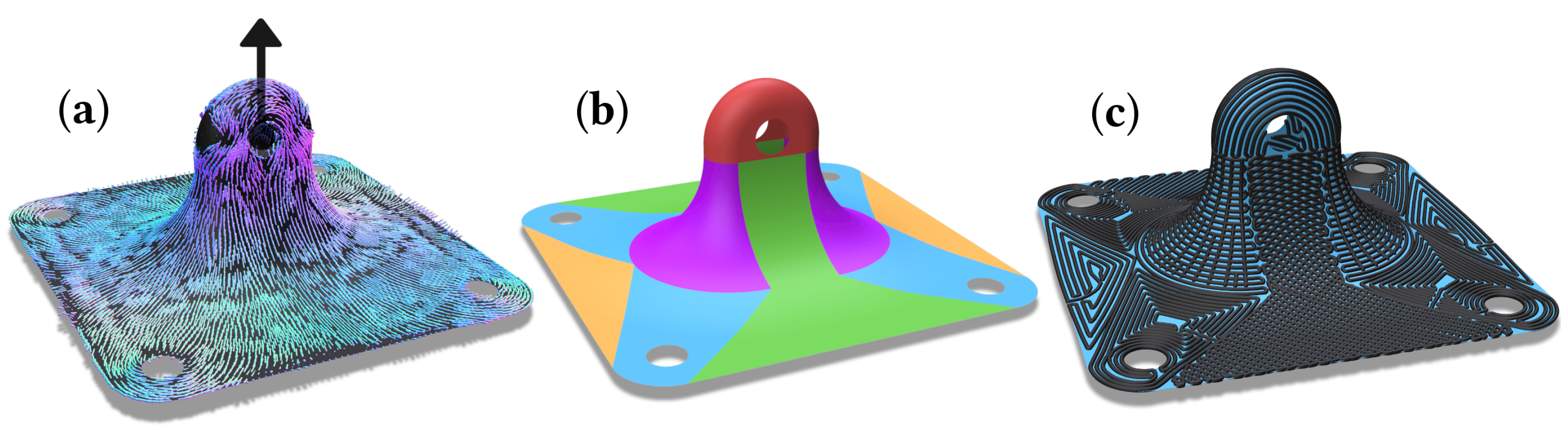
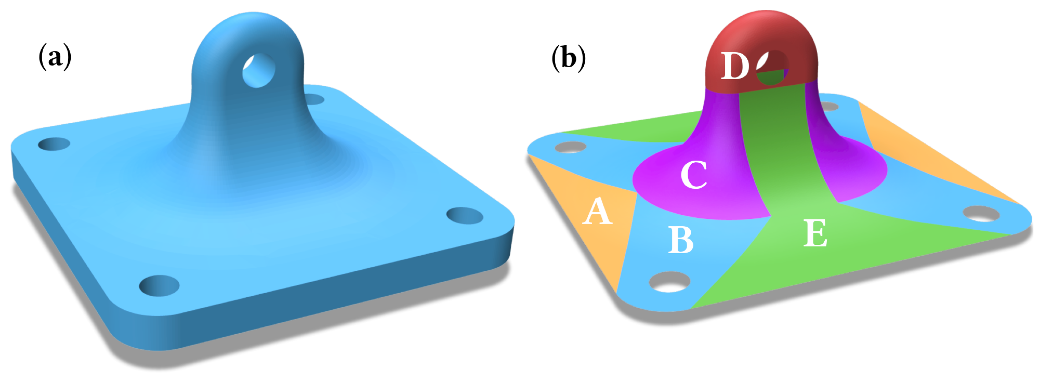
  • The proposed procedure starts by analyzing the part to be manufactured in an external finite element method (FEM) software to extract the major principle stress vectors. An exemplary result can be found in Figure 1a.
  • The resulting information enables the partitioning of the surface to be reinforced into subsurfaces with the goal of achieving a high compliance of local fiber direction and directions of major principle stress. Figure 1b illustrates such a partitioning. This is similar to the zoning approach, used in the layup process.
  • The subsurfaces are triangulated with high precision to ensure minimal computation error.
  • For every subsurface a suitable algorithm is chosen. This is performed with the intent of maximizing the measured values of the evaluation criteria and relies on knowledge of the procedures.
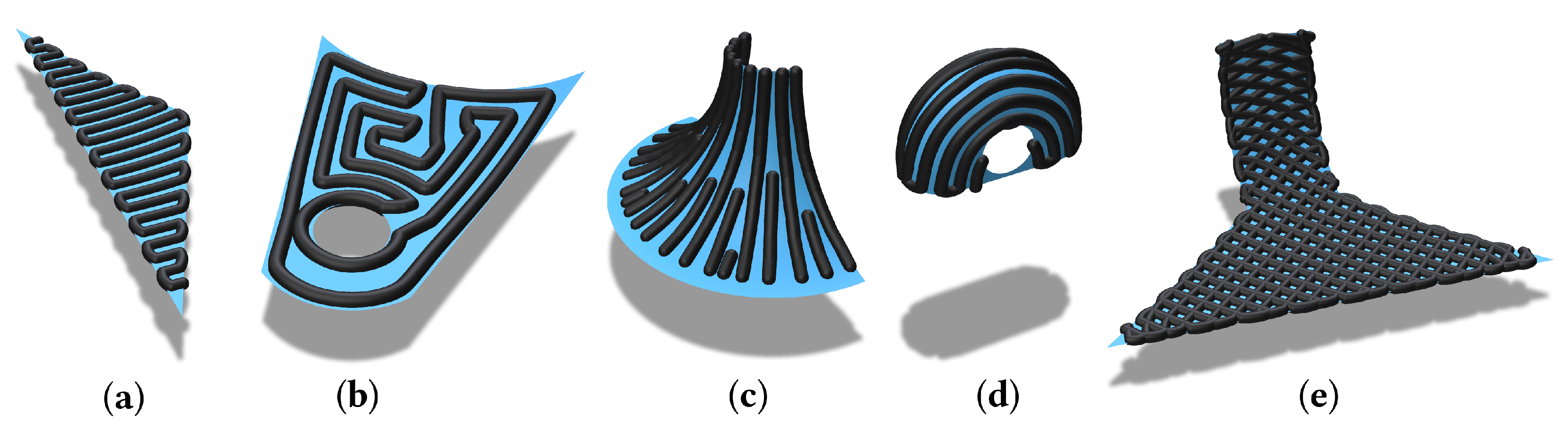
  • The chosen algorithm is executed for every surface resulting in paths that include possible travel motions, an example of which can be seen in Figure 1c.
  • Post-processing of the paths yields a Gcode to be executed on the multi-axis printer.
The focus of this paper will be the developed evaluation criteria and algorithms. The partitioning and the load cases for the finite element analysis (FEA) are subject to further optimization and will only be considered in an exemplary form. Some of the algorithms involve user input for choosing the most fitting fiber direction. This is motivated by the inability of current algorithms to deal with the high amount of divergence and turbulence observed in FEA results. This leads to the approaches discussed above that either only consider small areas of the entire dataset or the need to apply topology optimization, which can negatively effect the spectrum of possible applications. With user involvement at this step higher quality and consideration of the available data can be ensured, although automating this process may be considered for further research.

2. Methods and Evaluation Criteria

In this section, the process of extruding prepreg filament to form patches is analyzed to formulate the evaluation criteria that constitute the main analytical method. The manufacturing process begins by first printing the core volume with classical methods. On this core, the carbon fiber patches are applied increasing the overall structural integrity and interlaminar performance. To increase this effect the algorithms are designed to be able to align the filament to the main load transmission paths. This approach has been applied in [23,24]. Specifically, parts with open surfaces that cannot be manufactured by filament winding lend themselves to this approach.
In [23], it is stated that disordered stress distribution under different load conditions lead to the inability to follow stress distributions with a continuous path. They apply topological optimization which was not considered as an option in this work as explained above. This enables a higher quality surface finish with total coverage and eliminates the staircase effect often observed with planar FDM. Further elaboration on the process conditions and equipment such as the printing head and robotic setup for which this system was developed can be found in [11], although the algorithms presented in this paper are designed to work out of the box with any multi-axis system.
The software framework and the algorithms were developed in python with the help of the software library pyvista [26], a wrapper for vtk [27]. The user interface uses Qt5 [28] with pyqt [29] and numpy [30] was used extensively throughout. Distance computation was conducted by use of potpourri3d [31], networkx [32] was used for graph computations, scipy [33] for the savgol filter and trimesh [34] for subdiving, remeshing and intersecting the surface. The computer code for the algorithms will be made available upon request to the corresponding author.

2.1. Evaluation Criteria

The criteria on the path and properties of the surfaces to be reinforced are key for the goal-oriented formulation and development of the methods. They are chosen to minimize defects and allow the manufactured part to be of high quality. A lot of possible criteria such as isotropicity and manufacturability where addressed in the process of developing the algorithms, but the formal evaluation in this work will be limited to the four criteria presented in the following. As some of them are inversely correlated, trade-offs are discussed as well. The criteria are further illustrated by comparing them to similar aspects found in classical methods. Further elaboration on how the measured values for the criteria are obtained is included in Section 4.

2.1.1. Continuity

In general, discontinuities in the fiber are to be avoided as they lead to decreased tensile stress capacity. Here, the classical process of wrapping continuous fibers around a mandrel achieves the best results, while small patches of fabric for the layup process include a high number of discontinuities on the edges of the cut fabric. Additionally, the process of cutting the fiber in the printing head can lead to problems with the extrusion and could cause delays. This criterion is thus to be minimized to achieve a high efficiency and part quality.

2.1.2. Curvature

A major difference of the FDM process to classical methods is the high amount of local curvature in the path, as neither tape laying nor the layup process entail the placing of single bundles of fiber on open surfaces. It is still an active topic of research what the effect of high curvatures is on the mechanical properties of the resulting part, especially, for the case of fast changes in direction. Matsuzaki et al. identified the setting radius together with the fiber bundle size as the main parameters for printing quality [35]. Lower radii that are associated with high curvature lead to the inability to reach acceptable printing results. This motivates the assumption that high curvatures cause the brittle fiber bundles to fracture or twist, deteriorating the mechanical strength and lowering the printing accuracy, thus, this criterion is to be minimized.

2.1.3. Fiber Area Fraction

A common metric for the quality of fiber reinforced composites is the volume fraction. This measures the ratio of carbon fiber to the volume of a part. There are several methods of determining this important value and obtaining it is still an active topic of research, especially for parts manufactured with FDM. The presence of gaps or unfilled areas can serve as starting points for fractures and decrease the strength of the composite material. In this work, an equivalent measure is applied, but in a conceptual sense, meaning that the resulting index denotes the theoretical best value achieved by the path. The denomination as area fractions instead of volume fractions stems from the use of surfaces instead of volume bodies.

2.1.4. Load Adequacy

To enable a guided approach and fully utilize the possibility to regulate the direction and position of every fiber bundle, the load adequacy is taken as a criterion. To obtain an optimal direction of fibers the approach chosen in [23] is followed: the principle direction vectors are calculated from the FEA. As the fibers perform best under tensile stress, the direction of maximum principle stress is extracted and checked for alignment with the path in every point. This is sometimes called “principle of reinforcement” and the resulting fraction is to be maximized for best performance.

3. Algorithms

The algorithms described in the following aim to yield printing paths for reinforcement patches on additively manufactured structures. Partly adapted to fit this application from approaches in tape laying, classical 3D-slicing and CNC-machining, they are intended to serve as a starting point for non-planar path planning in manufacturing CFRP parts. In contrast to other approaches such as field-based methods, which struggle with divergence and turbulence, they are conceptualized to draw more from the geometry of the surface itself enabling a higher degree of control.
They are conceptually divided by their directionality, meaning the differentiation is performed in a classical way between direction parallel and contour parallel approaches. Generally, when working on non-planar manifold surfaces, the concept of direction in this sense is ambiguous. This is why several conceptually different methods for computing direction parallel paths are proposed. For the contour parallel approaches, the surface boundary is chosen as the outer contour, with the Geo-Spiral being an exception. The following algorithms are proposed:
  • Direction parallel:
    • Fixed intrinsic angle (FInA);
    • Fixed extrinsic angle (FExA);
    • Seeded ortho-isogeodesics (Ortheo).
  • Contour parallel:
    • Geodesic first in spiral out (Geo-FISO);
    • Geodesic contour parallel spirals (Geo-Contour);
    • Geodesic spiral around seed-point (Geo-Spiral).
One essential concept for most of the algorithms is the notion of geodesic distance. It is computed directly on the mesh using the heat method proposed in [36]. The surface is referred to as T as it is a triangulated mesh and the distance function will be denoted as ϕ . For distance computation, the eikonal equation | ϕ | = 1 with boundary conditions ϕ | γ = 0 over some subset of the domain γ (point or curve) is stated. This expression defines the distance function as giving the distance along the domain, being zero at the boundary γ . Further elaboration can be found in [36].

3.1. Direction Parallel Algorithms

When constructing direction parallel paths, the notion of angle is of importance. In a lot of cases the tensile strength of fibers is aimed to be maximally utilized by laying the fibers along the principle directions of stress. To achieve this directionality, while finding a good compromise to the other criteria, the following strategies are employed:

3.1.1. Fixed Intrinsic Angle (FInA)

To have a fixed or constant intrinsic angle of the fiber, the lines used for construction of the path are set to be equidistant to neighboring lines in all points. To construct lines with this property, curves of equal value on ϕ are computed with the intersecting plane P being chosen by the user. These isogeodesics are connected at the ends to obtain a continuous path as displayed in Figure 2a for an example surface. This procedure ensures a high density of fiber while retaining a notion of directionality. Drawbacks are high curvatures when changing directions and during travel motions.
The inputs for this algorithm are the triangular surface mesh T , the plane P, the spacing d and the travel height h r .
First, the mesh is split into two halves T 1 and T 2 by the plane P to retain a way of distinguishing the sides of the plane as ϕ is non-negative, which results in a multiplicity of curves for every distance. The seed curve γ for both meshes is calculated by intersecting the seed plane with the triangular surface mesh T . To obtain the geodesic distance, ϕ ( x p ) is evaluated for every point in the mesh.
The isogeodesic curves { c i } i = 1 , , n with c i = { x p | ϕ ( x p ) = i · d } are represented as points in space resulting from the interpolated value of the distance function on T 1 and T 2 , respectively.
For every c i , the points in the curve are connected to an ordered path segment s i ( k ) with k denoting the point index. To connect the lines, they are sorted by distance from the seed curve and iteratively appended to the resulting path. The order of traversal of a curve is reversed every iteration to ensure the back and forth movement. If c i has n discontinuities, travel motions are incorporated between the corresponding segments s i , 0 ( k ) to s i , n ( k ) by offsetting the respective boundary point by the travel height h r along the normal vector. Upon computing and connecting both sides, the path is resampled to obtain an even point distribution and smoothed by a Savitzky–Golay filter to eliminate sharp turns.

3.1.2. Fixed Extrinsic Angle (FExA)

It may be of importance to achieve a certain direction of fibers in an extrinsic way, meaning considered as lying in a Euclidean space of higher dimension, in this case, the ambient space of three dimensions. An example for when this would be preferred could be that the load conditions dictate a clear, extrinsic direction, but usage of FInA would result in an intolerable deviation due to high local curvature of the surface. Fibers cannot be tightly packed in this case. Another effect of using the extrinsic perspective is the line being regarded as extended, meaning upon reaching a boundary, the curve will extend over to a possible continuation on the surface. This is not the case for the intrinsic perspective. The drawbacks to this approach are that some surfaces lead to a high number of travel motions and inconsistent spacing can be observed on highly curved surfaces as can be seen in Figure 2b.
Computation differs minimally from FInA. The only difference being the usage of minimum euclidean distance from the plane P instead of geodesic distance from the curve γ . All other computation is conducted equivalently.

3.1.3. Seeded Ortho-Isogeodesics (Ortheo)

The core idea of this algorithm is to generate a path with subcurves that are orthogonal to the isogeodesics computed from a seed curve. This approach stems from the observation that the resulting path can be utilized in combination with the FInA algorithm to form a grid-like structure similar to the carbon fiber fabric used in layer stacking, which can be seen in Figure 3. This composition, where the fibers meet at right angles is unachievable by the classical method of draping a fabric, as the process of draping around a curvature necessarily introduces gaps in the cloth, which are filled with extra segments by the algorithm inducing the need for discontinuities. Additionally, it offers a new notion of directionality: at every point in the path the subcurves point along the gradient ϕ . It was hypothesized that the maximum principle directions would align with ϕ if the load is applied in the direction of this gradient at the boundary curves. The algorithm in its current form is in need of optimization for manufacturability as a lot of short segments are included in the path that, when regarding the distance between cutter and nozzle, can impede the ability to extrude the material. As this algorithm has not even been described for the planar case as of yet, the elaboration will be performed in more detail in the following.
The inputs for this algorithm are the triangular surface mesh T , the isocontour resolution d i s o , the spacing d, the travel height h r and a triangular mesh T s regarded as the “source mesh” from which the seed curve γ can be calculated. This is performed to enable the use of other existing components as the source, where the load could be applied.
Computation starts by finding γ from the intersection of T and T s . Like before, the isocontours c i = { x p | ϕ ( x p ) = i · d i s o } are extracted after applying the heat method, note the usage of d i s o for the distance between the isocontours instead of d. The set of path segments are initialized as 1-tupels S p a t h = { s j w i t h j 1 , , l a r c d } by extracting equidistant points from γ with spacing d and arc length l a r c of γ . The path segments are then grown by iterating over the c i . For every c i + 1 , the path segments s j are extended by finding the closest points in c i + 1 to the points s j ( i ) and appending it to the tupel. If the spacing between two chosen points s j ( i + 1 ) and s j + 1 ( i + 1 ) on c i + 1 exceeds d, a new path segment is started by inserting an additional s j into S p a t h and adjusting the indices for the every s l with l > j . This way, gaps between path segments, which emerge due to the curvature of the surface are filled with new path segments, decreasing the unfilled area and increasing the area fraction while maintaining the directionality of the paths. Similarly, when the spacing decreases enough, segments are ended and removed from S p a t h . The resulting path segments are resampled and smoothed by a Savitzky–Golay filter to eliminate sharp turns.
When the iteration reaches the last isocontour the path segments are connected with travel motions by offsetting start- and endpoints of the path segments by h r along the normal direction which yields the final path. A result of this procedure is displayed in Figure 2c for an exemplary surface. Because of the high amount of travel motions, a lot of cutting can occur when fiber paths are short. A possible improvement would be to significantly decrease the number of travel motions by implementing a back and forth motion in a weaving manner, as it cannot be achieved continuously due to the curvature-induced possibility that startpoints might be unreachable from previous endpoints without crossing already traversed regions.

3.2. Contour Parallel Algorithms

As was mentioned in the paragraphs above, the high maximum curvature of direction parallel paths is suspected to impede part quality due to fractures and twists of fibers. Additionally, surfaces with holes inevitably lead to travel motions in most situations. To avoid high curvatures and travel motions, the notion of contour parallel algorithm is introduced. These generally follow the boundary or contour and produce long segments with low curvature. They can also open the opportunity of load adequate path planning from a manufacturing perspective, similar to direction parallel paths, especially if the computed vectors of maximum principle stress closely follow a certain pattern in a subarea of the surface. This pattern can be extracted by the user and will then be followed by the path as the contour is traced and repeated inwards.
One general observation is to be made when dealing with contour parallel algorithms: ϕ can have several local maxima, making a spiral-like traversal nontrivial. Further description on why the local maxima lead to the impossibility for a trivial solution to the continuous path planning problem can be found in [37].

3.2.1. Geodesic First in Spiral Out (Geo-FISO)

The FISO Algorithm developed in [37] for the planar case offers a possibility for complete continuity with low curvature. The strategy of traversing isocontours by first directly moving into the maxima of the distance transform and then spiraling out along the contours allows for low curvature on inward and outward movement. This enables a continuous path to reach multiple local maxima of the distance transform without travel motions, which would not be possible with classical contour parallel algorithms. To demonstrate the algorithm on a complex and curved surface, the Stanford bunny with an open base was chosen as an exemplary surface as can be seen in Figure 4a.
The inputs for this algorithm are the triangular surface mesh T , the spacing d and the travel height h r .
γ is taken as the boundary of the surface. If the surface has holes, γ will have a multiplicity of subcurves from which ϕ is computed. The isocontours are again given by { c i } i = 1 , , n with c i = { x p | ϕ ( x p ) = i · d } with n discontinuities leading to continuous subcurves s i , j with j { 0 , , n } .
A weighted digraph G = { V , E } is then constructed with nodes v i , j V corresponding to the subcurves s i , j and edges E = { e i , j ; i + 1 , k | i , j , k } , i.e., connected for all nodes belonging to c i and c i + 1 . The weight function is given by f : E R + with f ( e i , j ; i + 1 , k ) = d m i n ( s i , j , s i + 1 , k ) , with d m i n denoting the minimum euclidean distance over all points in s i , j and s i + 1 , k , respectively. A minimum spanning tree T is then computed over this graph, yielding the connections that have to be made when linking the subcurves to a continuous path. This minimum spanning tree is traversed recursively starting with the root node v 0 , 0 which is always set as the outermost subcontour of γ . In each step of the recursion, the child nodes of the current node v i , j are continually checked for distance, while traversing the current contour and checking for possibilities to reroute from the current position to one of them and back. Once a possibility for rerouting is detected, meaning a segment where the distance between the curve and the current path stay below a threshold t d i s t for a n t h r e s h path points, the connection is created and a recursive call is made. Important for a correct connection is to detect the winding direction and connect the curves in the orientation that avoids crossing or overlaps. From experience, t d i s t is chosen as 1.2 · d to allow for some numerical buffer when rerouting the contours. The choice of n t h r e s h depends on the resampling resolution r r e s a m p l e with n t h r e s h = d r r e s a m p l e . Further description of the whole process for the planar case can be found in [37].
Generally, the usage of the geodesic distance from the boundary can lead to voids at the aforementioned local maxima of ϕ . Unwanted gaps can be created by contouring this function at the fixed values i · d if a local maximum at p fulfills ( j + 0.5 ) d < ϕ ( p ) < ( j + 1 ) d for some j. This is addressed by the next algorithm.

3.2.2. Geodesic Contour Parallel Spirals (Geo-Contour)

In some cases, the gaps created by missing contours in the local maxima are of concern as they are suspected to degrade material quality by introducing points where fractures or cracks form and decrease the fiber area fraction. To mitigate this, the global continuity is sacrificed in favor of spirals that travel into the maxima, filling them with a final path segment. This would not be achievable with the with Geo-FISO as two segments, created by splitting a closed curve, are needed to retain the inward-outward movement necessary for the algorithm. The approach described here is displayed in Figure 4b.
The inputs and first steps are identical to those in Geo-FISO. Upon obtaining the minimum spanning tree, all nodes v i , j with d e g r e e ( v i , j ) > 2 are denoted as rerouting contours and removed from the tree. The remaining connected components represent the “spiralable” areas. These are the areas around local maxima in ϕ , which can be attributed as belonging to this local maximum. The corresponding curves are then rerouted to obtain a continuous path. For each of these spirals, the points that lie at the local maximum are computed with special caution for numerical errors and an additional curve is appended to the path which traverses these points. After obtaining all spirals, they are connected by travel motions as before and the rerouting contours are traversed.

3.2.3. Geodesic Spiral around Seed-Point (Geo-Spiral)

The core focus in this algorithm is the continuous curvature of a circular path which was studied in [35], and thus, is better understood than the rapid and irregular direction changes in more classical path planning methods. By selecting a single seed point and creating a spiral that continually increases with geodesic distance, the observed high curvatures when changing directions incorporated in the preceding algorithms are prevented. The big drawback hereby being the inability to completely fill the surface with fiber, taking a hard toll on the fiber area fraction. Nevertheless, this algorithm serves to establish a good control for further testing and experimentation, when checking the material quality, as the induced gaps and the curvature are expected to be minimal.
The input to the algorithm is a point p s e e d T on the surface mesh, which is to be selected by a user, the triangular surface mesh T , the spacing d and the travel height h r . The selected point p s e e d serves as the seed γ for calculating the geodesic distance function ϕ via the heat method. As before, the isocontours c i are extracted from ϕ . For this algorithm, the procedure is terminated once a multiplicity is detected, resulting in the advantage of no travel motions and discontinuities, while sacrificing fiber area fraction. To this end, only the c i up to the first i are kept for which | { s i , j } j = 1 , , m | > 1 . These path segments are then reindexed to have their starting point with minimal distance to the boundary. This way, once the first contour is discontinuous due to hitting the boundary, it can be rerouted at the intersection point, including the open contours with no multiplicity in the path. If there are such open contours they are continued to be traversed with reversing directions until no further connections can be made.

4. Evaluation

The developed algorithms have been applied to a number of problems in the process of development to study their behavior and adherence to the aforementioned criteria. The following exemplary part and resulting surfaces have been constructed to cover a wide variety of edge cases to serve a better understanding of the algorithm’s behavior. An exemplary planned path can be seen in Figure 1c. The part’s geometry and by extension the analysis is not exhaustive. This evaluation is meant to serve as a starting point and explanation of the general procedure.
The part used in this evaluation resembles an angle bracket with continuously curved surfaces as can be seen in Figure 5a. The FEA, design and partitioning as explained in Section 1.2 has been performed in FreeCAD and Autodesk ® Fusion360. The load cases examined here are displayed in Figure 6. These are chosen to model a weight exerting force on the angle bracket in a position where the bracket is mounted on a wall or ceiling. As only the maximum principle directions are of interest, the vectors are displayed in normalized form. Upon analysis of the part, taking the shown directions into account, a partitioning into five different surfaces is chosen according to the maximum principle directions, as seen in Figure 5b. The process of partitioning is performed by feature and visually based manual user input. Here, knowledge of the algorithms resulting directionality is required to produce a partitioning that delivers a good result. How many subsurfaces are to be constructed depends on the specific load cases and the part geometry. This is similar to the industry practice of zone-based design in the production of carbon fiber composites in the layup process.

4.1. Evaluation Criteria

Every criterion is evaluated without taking segments of travel motions into account, meaning that only the path segments lying on the surface are considered. As the means of acquiring the indices for the criteria are pivotal they are described in the following.

4.1.1. Continuity

Measuring continuity is simply performed by counting the number of rerouting procedures needed to follow the path which corresponds exactly to the number of discontinuities.

4.1.2. Curvature

This criterion is meant to give an index on whether the path contains high curvatures which might induce fractures in the fibers and twists in the fiber bundles, diminishing material quality. For every point in the path, the angle is computed as α ( i ) = a r c c o s ( p i p i 1 , p i + 1 p i ) with the angles for start- and endpoints of each continuous segment being set to zero. To the end of extracting a meaningful indication on how high the curvature is when changing direction, only the top 1% of computed angles are selected and the mean is calculated yielding the value for this criterion.

4.1.3. Fiber Area Fraction

To compute the fiber area fraction, the area A s of the triangulated surface is first extracted by summing the area of its triangles. Then, the geodesic distance field ϕ p a t h on the mesh is calculated with the path points serving as the source γ . The area for which ϕ p a t h ( x p ) > d is the uncovered area A u . This is calculated by summing the triangle areas of a subdivided mesh, where all vertices fulfill ϕ p a t h ( x p ) > d . Lastly 1 A u A s gives us the index for the area fraction. This value indicates the amount of used area, with 0 representing no fiber deposited and 1 meaning complete coverage.

4.1.4. Load Adequacy

The index for load adequacy is calculated for every point excluding the last point in the path by finding the closest maximum principle direction vector v from the data set and checking for alignment by computing the dot product v , u with the vector u = p i p i + 1 connecting the current point with the next one. Before calculation u is normalized, as the sign does not matter in this case, the absolute value of the resulting dot product is taken. If several load cases are to be examined at this point, the highest alignment is chosen. Finally, the index for load adequacy is calculated as the mean of the computed dot products for all points. This value will be between 0 and 1 representing the amount of alignment with the load transmission paths.

4.2. Results

Of all possible combinations of the surfaces depicted in Figure 5b and all the algorithms, ten were chosen and analyzed. These have been selected to cover all algorithms in several scenarios, the only exception being Ortheo and Geo-Spiral as the performance is evident from one test. The results from this evaluation are shown in Table 1 and a selection of the chosen combinations can be seen in Figure 7a–e. What can be observed is that the Geo-Contour and Geo-FISO algorithms show a low curvature while maintaining a level of fiber area fraction and load adequacy. The direction parallel algorithms excluding Ortheo show higher curvature because of the sharper angles when changing directions but have a consistently high fiber area fraction. They can be observed to incorporate discontinuities for parts with holes or complex and large surfaces. Ortheo yields especially high load adequacy and the lowest curvature while introducing a lot of discontinuities as expected. Geo-Spiral performs poorly in every aspect with even curvature being high, which is suspected to have its cause in the rerouting, which could be improved by smoother transitions. In total, the results show the trade-offs and differences supporting the claim that having multiple algorithms is necessary to adapt to the varying conditions when planning the reinforcement patches.
To the end of analyzing the variety of applications, a qualitative feature-based matching is made in the following. All algorithms are numerically stable and deliver results in edge cases, as well as highly curved surfaces. Additionally, computation times were observed to be in the lower minute range. The primitive cartesian smoothing with the Savitzky–Golay filter can lead to collisions with the surface for highly curved surfaces if its degree is set too high.

4.2.1. Direction Parallel Algorithms

The direction parallel algorithms exhibit a higher degree of control outside the partitioning as the direction can be set. The user-defined seed curve has a direct influence on the results and is as relevant as the subsurface boundary and thus underlies the same principle of user experience being necessary in application. In general, the performance of direction parallel algorithms correlated with the relative dimension in the chosen direction. Especially for long and thin parts this choice has an effect. Additionally, highly concave structures lead to a sharp increase in travel motions for the direction parallel algorithms as such gaps prevent the movements from being achieved without discontinuities.

4.2.2. Contour Parallel Algorithms

The major influencing factor for the performance of the contour parallel algorithms is the boundary geometry and the resulting distance field. If ϕ has a high number of maxima Geo-Contour will show a lot of travel motions. In this case, the choice of Geo-FISO is favorable. Geo-Spiral has a major dependency on boundary geometry. On convex and highly curved surfaces it can terminate due to the isocontours self intersecting. Thus, complex geometries with protruding features lead to a poor performance. In summary, Geo-FISO offers the best performance for the widest applicability.

5. Conclusions

A procedure is proposed in this paper including six algorithms for planning paths of reinforcement patches on complex and curved surfaces. This represents an important step into field planning paths for the multi-axis manufacture of CFRPs with FDM which is currently one of the major bottlenecks for this process. Evaluation criteria were formulated and motivated by the process to enable the guided development and serve as a metric for methods developed in the future. The algorithms were described and evaluated regarding the established criteria to assess the applicability and the spectrum of possible surfaces to be covered. The concept of isocontours on geodesic fields is employed to yield paths with low curvature, high fiber density, few discontinuities and high load adequacy. Methods to obtain these values were developed and applied to measure the performance of the algorithms. The presented results show promising capabilities for this application and others such as planning paths of slices when constructing a volume body. To develop and evaluate such an approach will be highly beneficial for load adequacy as no multi-axis slicer software for CFRPs has yet been made available.
Further work includes the possibility for some of the proposed methods such as Geo-Spiral to be optimized to enable termination under less restrictive conditions and further increase performance. Domain-based smoothing could eliminate defects introduced by currently used smoothing methods. Additional analysis of the process of partitioning and the load cases for FEA is needed to increase the applicability of the described methods and quality of results. An automation of partitioning and planning would be favorable, as user experience and knowledge of algorithms is still required in the process. Moreover, a comprehensive evaluation and experimental validation is needed to increase the effectiveness of the deployment and application.
This paper precedes any complete analysis of the multi-axis manufacturing process for CFRPs including slicing, construction and planning and gives a starting point for the promising field of planning paths for CFRPs manufactured by use of FDM.

Author Contributions

Conceptualization, J.K. and T.S.; methodology, J.K.; software, J.K.; formal analysis, J.K.; investigation, J.K. and Z.K.; resources, J.K. and Z.K.; writing—original draft preparation, J.K.; writing—review and editing, Z.K. and T.S.; visualization, J.K.; supervision, Z.K. and T.S.; project administration, T.S.; funding acquisition, T.S. All authors have read and agreed to the published version of the manuscript.

Funding

This research was funded through the I3 program (Interdisciplinary, Innovative, Engineering (German: Ingenieurwissenschaften)) of the Hamburg University of Technology.

Institutional Review Board Statement

Not applicable.

Informed Consent Statement

Not applicable.

Data Availability Statement

Computer code will be made available upon request to the corresponding author.

Conflicts of Interest

The authors declare no conflict of interest.

Abbreviations

The following abbreviations are used in this manuscript:
AMAdditive manufacturing
CFRPCarbon fiber reinforced polymers
FDMFused deposition modeling
PrepregPre-impregnated
FEMFinite element methods
FEAFinite element analysis
FInAFixed intrinsic angle
FExAFixed extrinsic angle
OrtheoSeeded ortho-isogeodesics
Geo-FISOGeodesic first in spiral out
Geo-ContourGeodesic contour parallel spirals
Geo-SpiralGeodesic spiral around seed-point

References

  1. Sanei, S.H.R.; Popescu, D. 3D-Printed Carbon Fiber Reinforced Polymer Composites: A Systematic Review. J. Compos. Sci. 2020, 4, 98. [Google Scholar] [CrossRef]
  2. Pandelidi, C.; Bateman, S.; Piegert, S.; Hoehner, R.; Kelbassa, I.; Brandt, M. The technology of continuous fibre-reinforced polymers: A review on extrusion additive manufacturing methods. Int. J. Adv. Manuf. Technol. 2021, 113, 3057–3077. [Google Scholar] [CrossRef]
  3. Dickson, A.N.; Abourayana, H.M.; Dowling, D.P. 3D Printing of Fibre-Reinforced Thermoplastic Composites Using Fused Filament Fabrication-A Review. Polymers 2020, 12, 2188. [Google Scholar] [CrossRef] [PubMed]
  4. Becker, C.; Oberlercher, H.; Heim, R.B.; Wuzella, G.; Faller, L.M.; Riemelmoser, F.O.; Nicolay, P.; Druesne, F. Experimental Quantification of the Variability of Mechanical Properties in 3D Printed Continuous Fiber Composites. Appl. Sci. 2021, 11, 1315. [Google Scholar] [CrossRef]
  5. Zhang, H.; Huang, T.; Jiang, Q.; He, L.; Bismarck, A.; Hu, Q. Recent progress of 3D printed continuous fiber reinforced polymer composites based on fused deposition modeling: A review. J. Mater. Sci. 2021, 56, 12999–13022. [Google Scholar] [CrossRef]
  6. Huang, H.; Liu, W.; Liu, Z. An additive manufacturing-based approach for carbon fiber reinforced polymer recycling. CIRP Ann. 2020, 69, 33–36. [Google Scholar] [CrossRef]
  7. Saccani, A.; Fiorini, M.; Manzi, S. Recycling of Wastes Deriving from the Production of Epoxy-Carbon Fiber Composites in the Production of Polymer Composites. Appl. Sci. 2022, 12, 4287. [Google Scholar] [CrossRef]
  8. Zhang, K.; Zhang, W.; Ding, X. Multi-axis additive manufacturing process for continuous fibre reinforced composite parts. Procedia CIRP 2019, 85, 114–120. [Google Scholar] [CrossRef]
  9. Zhuo, P.; Li, S.; Ashcroft, I.A.; Jones, A.I. Material extrusion additive manufacturing of continuous fibre reinforced polymer matrix composites: A review and outlook. Compos. Part Eng. 2021, 224, 109143. [Google Scholar] [CrossRef]
  10. Wulle, F.; Coupek, D.; Schäffner, F.; Verl, A.; Oberhofer, F.; Maier, T. Workpiece and Machine Design in Additive Manufacturing for Multi-Axis Fused Deposition Modeling. Procedia CIRP 2017, 60, 229–234. [Google Scholar] [CrossRef]
  11. Kallai, Z.; Dammann, M.; Schueppstuhl, T. Operation and experimental evaluation of a 12-axis robot-based setup used for 3D-printing. In Proceedings of the ISR 2020, 52th International Symposium on Robotics, Online. 9–10 December 2020; pp. 1–9. [Google Scholar]
  12. Such, M.; Ward, C.; Potter, K. Aligned Discontinuous Fibre Composites: A Short History. J. Multifunct. Compos. 2014, 2, 155–168. [Google Scholar] [CrossRef]
  13. Chen, X.; Fang, G.; Liao, W.H.; Wang, C.C. Field-Based Toolpath Generation for 3D Printing Continuous Fibre Reinforced Thermoplastic Composites. Addit. Manuf. 2022, 49, 102470. [Google Scholar] [CrossRef]
  14. Li, Y.; Xu, K.; Liu, X.; Yang, M.; Gao, J.; Maropoulos, P. Stress-oriented 3D printing path optimization based on image processing algorithms for reinforced load-bearing parts. CIRP Ann. 2021, 70, 195–198. [Google Scholar] [CrossRef]
  15. Yao, Y.; Zhang, Y.; Aburaia, M.; Lackner, M. 3D Printing of Objects with Continuous Spatial Paths by a Multi-Axis Robotic FFF Platform. Appl. Sci. 2021, 11, 4825. [Google Scholar] [CrossRef]
  16. Li, Y.; He, D.; Wang, X.; Tang, K. Geodesic Distance Field-based Curved Layer Volume Decomposition for Multi-Axis Support-free Printing. arXiv 2020, arXiv:2003.05938. [Google Scholar]
  17. Schueler, K.; Miller, J.; Hale, R. Approximate Geometric Methods in Application to the Modeling of Fiber Placed Composite Structures. J. Comput. Inf. Sci. Eng. 2004, 4, 251–256. [Google Scholar] [CrossRef]
  18. Han, Z.; Qiangqiang, F.; Fan, Y.; Yunzhong, F.; Hongya, F. A Path Planning Algorithm of Closed Surface for Fiber Placement. In Proceedings of the 1st International Conference on Mechanical Engineering and Material Science, Prague, Czech Republic, 28–30 December 2012; Atlantis Press: Paris, France, 2012. [Google Scholar] [CrossRef] [Green Version]
  19. Hély, C.; Birglen, L.; Xie, W.F. Feasibility study of robotic fibre placement on intersecting multi-axial revolution surfaces. Robot. Comput.-Integr. Manuf. 2017, 48, 73–79. [Google Scholar] [CrossRef]
  20. Xiao, H.; Han, W.; Tang, W.; Duan, Y. An Efficient and Adaptable Path Planning Algorithm for Automated Fiber Placement Based on Meshing and Multi Guidelines. Materials 2020, 13, 4209. [Google Scholar] [CrossRef]
  21. Rousseau, G.; Wehbe, R.; Halbritter, J.; Harik, R. Automated Fiber Placement Path Planning: A state-of-the-art review. Comput.-Aided Des. Appl. 2018, 16, 172–203. [Google Scholar] [CrossRef] [Green Version]
  22. Li, N.; Link, G.; Wang, T.; Ramopoulos, V.; Neumaier, D.; Hofele, J.; Walter, M.; Jelonnek, J. Path-designed 3D printing for topological optimized continuous carbon fibre reinforced composite structures. Compos. Part Eng. 2020, 182, 107612. [Google Scholar] [CrossRef]
  23. Wang, T.; Li, N.; Link, G.; Jelonnek, J.; Fleischer, J.; Dittus, J.; Kupzik, D. Load-dependent path planning method for 3D printing of continuous fiber reinforced plastics. Compos. Part Appl. Sci. Manuf. 2021, 140, 106181. [Google Scholar] [CrossRef]
  24. Kim, J.; Kang, B.S. Enhancing Structural Performance of Short Fiber Reinforced Objects through Customized Tool-Path. Appl. Sci. 2020, 10, 8168. [Google Scholar] [CrossRef]
  25. Bere, P.; Neamtu, C.; Udroiu, R. Novel Method for the Manufacture of Complex CFRP Parts Using FDM-based Molds. Polymers 2020, 12, 2220. [Google Scholar] [CrossRef] [PubMed]
  26. Sullivan, C.B.; Kaszynski, A. PyVista: 3D plotting and mesh analysis through a streamlined interface for the Visualization Toolkit (VTK). J. Open Source Softw. 2019, 4, 1450. [Google Scholar] [CrossRef]
  27. Schroeder, W.; Martin, K.; Lorensen, B. The Visualization Toolkit—An Object-Oriented Approach to 3D Graphics, 4th ed.; Kitware, Inc.: New York, NY, USA, 2006. [Google Scholar]
  28. The Qt Company Ltd. Qt 5.15. Available online: https://doc.qt.io/qt-5.15/ (accessed on 2 May 2022).
  29. Riverbank Computing Limited. PyQt5 Reference Guide. 2021. Available online: https://www.riverbankcomputing.com/static/Docs/PyQt5/ (accessed on 2 May 2022).
  30. Harris, C.R.; Millman, K.J.; van der Walt, S.J.; Gommers, R.; Virtanen, P.; Cournapeau, D.; Wieser, E.; Taylor, J.; Berg, S.; Smith, N.J.; et al. Array programming with NumPy. Nature 2020, 585, 357–362. [Google Scholar] [CrossRef]
  31. Sharp, N. potpourri3d. 2022. Available online: https://github.com/nmwsharp/potpourri3d (accessed on 2 May 2022).
  32. Hagberg, A.A.; Schult, D.A.; Swart, P.J. Exploring network structure, dynamics, and function using NetworkX. In Proceedings of the 7th Python in Science Conference (SciPy2008), Pasadena, CA, USA, 19–24 August 2008; pp. 11–15. [Google Scholar]
  33. Virtanen, P.; Gommers, R.; Oliphant, T.E.; Haberland, M.; Reddy, T.; Cournapeau, D.; Burovski, E.; Peterson, P.; Weckesser, W.; Bright, J.; et al. SciPy 1.0: Fundamental Algorithms for Scientific Computing in Python. Nat. Methods 2020, 17, 261–272. [Google Scholar] [CrossRef] [Green Version]
  34. Dawson-Haggerty, M. Trimesh. 2022. Available online: https://github.com/mikedh/trimesh (accessed on 2 May 2022).
  35. Matsuzaki, R.; Nakamura, T.; Sugiyama, K.; Ueda, M.; Todoroki, A.; Hirano, Y.; Yamagata, Y. Effects of Set Curvature and Fiber Bundle Size on the Printed Radius of Curvature by a Continuous Carbon Fiber Composite 3D Printer. Addit. Manuf. 2018, 24, 93–102. [Google Scholar] [CrossRef]
  36. Crane, K.; Weischedel, C.; Wardetzky, M. The Heat Method for Distance Computation. Commun. ACM 2017, 60, 90–99. [Google Scholar] [CrossRef]
  37. Harnisch, M.; Kipping, J.; Schueppstuhl, T. Evaluation of path planning strategies in automated honeycomb potting. In Proceedings of the ISR 2020, 52th International Symposium on Robotics, Online. 9–10 December 2020; pp. 1–7. [Google Scholar]
Figure 1. (a) Maximum principle stress vectors resulting from finite element analysis (FEA). (b) Decomposition of part into subsurfaces. (c) Exemplary planned paths for all subsurfaces with d = 1 mm. Filament thickness displayed does not correspond to thickness when printed.
Applsci 12 05819 g001
Figure 2. Direction parallel algorithms and resulting paths. Travel motions are not displayed. With d = 1 mm (a) FInA, (b) FExA, (c) Ortheo. Filament thickness displayed does not correspond to thickness when printed.
Applsci 12 05819 g002
Figure 3. A grid-like structure in the spirit of draped carbon fiber fabric resulting from layering paths generated by the Ortheo and FInA algorithms. This result is unachievable with classical methods such as tape-laying or hand layup. Filament thickness displayed does not correspond to thickness when printed.
Applsci 12 05819 g003
Figure 4. Contour parallel algorithms and resulting paths on the Stanford bunny. Travel motions not displayed. With d = 3.5 mm (a) Geo-FISO, (b) Geo-Contour, (c) Geo-Spiral. Filament thickness displayed does not correspond to thickness when printed.
Applsci 12 05819 g004
Figure 5. (a) Part for evaluation (b) Partitioning of surfaces.
Applsci 12 05819 g005
Figure 6. FEA with the load cases and the maximum principle directions. (a) Load case Y. (b) Load case X.
Applsci 12 05819 g006
Figure 7. (a) FExA on surface A (b) Geo-FISO on surface B (c) Ortheo on surface C with surface D as source with d i s o = 1 mm (d) FInA on surface D (e) FInA twice with orthogonal planes on surface E. For all paths d = 2 mm for illustration purposes, planes chosen to align with the vector field. Filament thickness displayed does not correspond to thickness when printed.
Applsci 12 05819 g007
Table 1. Evaluation criteria for the chosen combinations of surface and algorithm 1.
ParametersResults
Surface ( T )AlgorithmLoad CaseMean Curv. (1%)Fiber Area FractionLoad AdequacyDiscontinuities
AGeo-ContourX + Y26.35°0.870.780
AFExAX + Y29.7°0.90.820
BGeo-FISOX + Y28.2°0.850.660
BFExAX + Y39.25°0.920.936
COrtheo T s = DY4.2°0.840.9839
CFInAY61.55°0.930.850
DGeo-SpiralY43.02°0.330.430
DFInAY50°0.910.724
EFInA + FInAX58.5°0.920.841
EGeo-ContourX51.6°0.90.830
1 Fixed parameters: d = 1 mm, diso = 1 mm, planes chosen to align with vector field.
Publisher’s Note: MDPI stays neutral with regard to jurisdictional claims in published maps and institutional affiliations.

