Article

Pixel Resolution Imaging in Parallel Phase-Shifting Digital Holography

1
Changchun Institute of Optics, Fine Mechanics and Physics, Chinese Academy of Sciences, Changchun 130033, China
2
University of Chinese Academy of Sciences, Beijing 100049, China
*
Author to whom correspondence should be addressed.
Appl. Sci. 2022, 12(12), 5812; https://doi.org/10.3390/app12125812
Submission received: 6 April 2022 / Revised: 28 May 2022 / Accepted: 30 May 2022 / Published: 8 June 2022
(This article belongs to the Section Optics and Lasers)

Abstract

:
Parallel phase-shifting digital holography (PPSDH) employing a polarization image sensor can suppress zero-order and twin-image noise through a single exposure, achieve instantaneous measurement of complex-valued dynamic objects, and have broad applications in the areas of biomedicine, etc. To improve the imaging resolution of PPSDH, we propose an oversampled super-pixel image reconstruction method, which can be expressed as the implementation of nearest-neighbor interpolation to replace blank pixels in sparse sub-phase-shift holograms. We found experimentally that the maximum spatial lateral resolution of the reconstructed image based on the existing super-pixel method, B-spline, bicubic, bilinear, and the proposed nearest-neighbor interpolation was 12.4 µm, 11.4 µm, 9.8 µm, 8.8 µm, and 7.8 µm, respectively. The main reason for not reaching the ideal value of 6.9 µm was the inherent residual zero-order and twin-image noise, which needs to be removed in the future.

1. Introduction

Digital holography (DH) enables two-dimensional quantitative complex amplitude imaging or simultaneous amplitude and phase imaging, which is a very powerful method for metrology, analysis, and detection, with broad applications in the areas of biomedicine, instrument manufacturing, aquatic science, extraterrestrial life detection, 3D imaging and displays, security and defense, etc. [1,2,3,4]. Zero-order and twin-image noise are serious obstacles to achieving high-quality imaging in in-line DH, and the phase-shifting (PS) technique is often required for noise suppression. Among the existing noise removal techniques, the traditional temporal PS technique can theoretically provide the best quality of reconstructed images [5,6]. However, due to the nonlinear response and response time of practical PS devices such as piezoelectric transducers, temporal phase-shifting digital holography (PSDH) has the following drawbacks: (1) it is extremely sensitive to environmental vibration and turbulence; (2) the relative phase shifts between interferograms cannot be precisely controlled [7,8]; and (3) real-time measurement of fast-moving targets is not possible [9,10].
To exceed the limitations of PSDH, Y. Awatsuji et al. proposed parallel phase-shifting digital holography (PPSDH) in 2004, using an optical-path-length-shifting array device with a pixelated periodic thickness distribution, or a micropolarizer array device with a pixelated periodic polarization direction distribution, to capture multiple digital holograms with different phase shifts in a single exposure [9,11,12,13,14,15]. The spatial PS technique based on the pixelated polarization mask has the advantages of being essentially simple to align and compose, achromatic over a wide range, etc. [13,16], but also has the drawback that there was no available commercial cost-effective polarization camera until the launch of the polarization-dedicated image sensor IMX250MZR by Sony for snapshot polarization imaging in 2018 [17,18,19]. The IMX250MZR sensor, with an image resolution of 2448 × 2048 and a pixel pitch of 3.45 µm, not only promotes the development of snapshot polarization imaging, but also solves the core device problem of PPSDH, and enables PPSDH to be more widely studied [20,21,22,23,24,25,26,27].
Similar to polarization imaging, “hologram demosaicing” is also a crucial imaging pipeline of PPSDH [28,29,30]. There are currently two classical demosaicing methods in PPSDH: the first is the super-pixel method (SPM), which discards the blank pixels in the sparse sub-phase-shift holograms [16,31,32]; and the second is the hologram interpolation method (HIM), which uses adjacent pixel values instead of blank pixels [9]. Among them, the SPM, which regards a set of four neighboring pixels corresponding to the four phase shifts as a “unit cell”, is simple to implement, but can only calculate the complex amplitude value of the optical field at one point, resulting in the maximum lateral spatial resolution and image resolution of the reconstructed image of PPSDH both being reduced to one-half of that of PSDH in the horizontal and vertical directions, respectively. Although the HIM is more complex than the SPM, it can avoid the loss of image resolution [23]. Xia, P et al. compared the root-mean-square error of the reconstructed image by the HIM based on bilinear, bicubic, and B-spline through simulation in 2013 [30], and after that there has been no specific analysis of the differences between the SPM and the HIM in PPSDH.
Lateral spatial resolution is one of the main parameters of PPSDH. To solve the problem of limited lateral resolution caused by the decrease in the sampling frequency of the traditional SPM in practical applications, we propose an oversampled super-pixel method (OSPM), referring to the sensor-shifting implementation of pixel super-resolution (PSR) for on-chip lensless digital holographic microscopy (DHM) [33,34]. The proposed OSPM can not only achieve pixel resolution imaging in PPSDH, but also can be represented in the form of an HIM based on nearest-neighbor interpolation for comparing the differences between the SPM and HIM. In Section 2, the principles and methods of the proposed technique are explained. The experimental verification of the proposed technique and discussion of the results are shown in Section 3, which is followed by the conclusions in Section 4.

2. Principles and Methods

2.1. Hologram Recording

Figure 1 shows the optical schematic of the PPSDH system based on the Mach–Zehnder interference structure. A polarized He–Ne laser source (Thorlabs HNL020LB) with a wavelength of 632.8 nm, whose output amplitude is continuously adjusted by a polarizer, acts as the source beam for the proposed PPSDH system. The beam is spatially filtered and collimated to generate a uniform beam with a plane wavefront. The ratio of the p-polarized and s-polarized components of the source’s linearly polarized light is continuously adjusted by a half-wave plate (HWP). The reflected beam (s-polarized) from a polarizing beam splitter (PBS) illuminates the transparent object, and the illumination light is modulated by the complex amplitude of the object to form the object beam u ( x , y ) , while the transmitted beam (p-polarized) acts as the plane wavefront reference beam. The object diffracted beam and the reference beam are combined by a non-polarizing beam splitter (BS), and their polarization states become right-handed circular polarization and left-handed circular polarization, respectively, through a quarter-wave plate (QWP) with the fast axis oriented at −π⁄4. The polarization direction of the object diffracted beam o ( x , y ) (right-handed) and the reference beam r ( x , y ) (left-handed) at the plane of the monochromatic polarization camera (FLIR BFS-U3-51S5P-C) has the same rotational angular velocity, but in opposite directions. Thus, relative phase shifts of δ = 0, π/2, π, 3π/2 are formed between the object beam and the reference beam through a micropolarizer filter array with the optical axis direction of 0, π/4, π/2, 3π/4. Due to the circular arrangement of a set of 2 × 2 adjacent pixels with different polarization directions, the four sub-phase-shift holograms I 0 ( x , y ; 0 ) , I 0 ( x , y ; π / 2 ) , I 0 ( x , y ; π ) , I 0 ( x , y ; 3 π / 2 ) in a spatially multiplexed hologram I 0 ( x , y ; δ ) (SMH) recorded by the polarization camera are also cross-distributed, as in a checkerboard [7,26,27,35,36].

2.2. Hologram Reconstruction

Figure 2 illustrates the SPM calculation procedure of image reconstruction for PPSDH [16,31,32]. Pixels with the same phase shifts are extracted to obtain four sparse sub-phase-shift holograms: I 0 ( x , y ; 0 ) , I 0 ( x , y ; π / 2 ) , I 0 ( x , y ; π ) , and I 0 ( x , y ; 3 π / 2 ) . The SPM obtains four aligned phase-shift holograms— I ( x , y ; 0 ) , I ( x , y ; π / 2 ) , I ( x , y ; π ) , and I ( x , y ; 3 π / 2 ) —by downsampling the sparse sub-holograms and discarding the blank pixels. The PS technique provides complex amplitude distribution of the object diffracted beam o ( x , y ) at the plane of the image sensor, and the diffraction calculation of o ( x , y ) is performed by the angular spectrum method (ASM) to obtain the reconstructed image of the object beam u ( x , y ) , using the following equations [26,37]:
o ( x , y ) = [ I ( x , y ; 0 ) I ( x , y ; π ) ] + j [ I ( x , y ; π / 2 ) I ( x , y ; 3 π / 2 ) ]
u ( x , y ) = 1 { [ o ( x , y ) ] e x p [ j k z 1 ( λ f x ) 2 ( λ f y ) 2 ] }
where and 1 denote the Fourier transform and inverse Fourier transform, respectively; k = 2π/λ is the wave number; λ is the wavelength of the illumination light source; z is the numerical diffraction propagation distance, which is equal to the recorded distance from the object to the sensor; and ( f x , f y )   represents the two-dimensional spatial frequency components.
The object diffracted field o ( x , y ) calculated by the SPM can be equivalently regarded as the result of direct sampling of o ( x , y ) by an imaginary light-field image sensor with a pixel pitch of 2 and an image resolution of N x × N y / 4 , where N x , N y and   represent the image resolution and the pixel pitch of the actual sensor, respectively. Considering the horizontal direction, a frequency sampling bandwidth of B S P x = 1 / 2 corresponding to the 2 super-pixel (SP) sampling interval of the light-field sensor filters out high-frequency information beyond B S P x in the diffraction field, with a bandwidth of B x = N x / λ z : (1) when B S P x > B x , the imaging lateral resolution mainly depends on B x ; (2) when B S P x < B x , the lateral resolution mainly depends on B S P x , and is not more than twice the sampling interval of the light-field sensor, which equals 4 in the SPM. Therefore, the lateral resolution can be improved by reducing the sampling interval or increasing the sampling bandwidth of the imaginary light-field sensor.
To solve the above problem of the SPM, we propose an OSPM for PPSDH, referring to PSR for on-chip DHM [33,34]; Figure 3 depicts the proposed technique. As shown in Figure 3a, the OSPM calculates four object light diffraction field images by overlapping each independent SP, which is equivalent to four images captured after moving the imaginary light-field sensor in the horizontal and vertical directions by half an SP offset. After interpolating and merging four low-resolution images, a light-field image with an SP interval of and an image resolution of N x × N y   can be obtained. Figure 3b shows that the implementation of the OSPM for enhancing the sampling frequency of the light field can be simplified to perform nearest-neighbor interpolation on the extracted sparse phase-shift holograms I 0 ( x , y ; δ ) in the form of HIM, obtain four interpolated aligned phase-shift holograms I ( x , y ; δ ) , and calculate the object light field u ( x , y ) according to Equations (1) and (2). Compared with the traditional numerical calculation implementation of interpolation [23,30], a simpler implementation can be represented by the convolution of an image and an interpolation kernel using the following equation [26]:
I ( x , y ; δ ) = I 0 ( x , y ; δ ) f ( x , y )
where ∗ denotes the convolution operation, and f ( x , y ) represents the interpolation kernel. Table 1 shows the classical convolutional interpolation kernels, including nearest-neighbor interpolation [31]. To reduce the calculation time, [26] proposed a fast image reconstruction technique based on the convolution theorem.
The proposed OSPM increases the frequency sampling bandwidth of the object light diffraction field from B S P x = 1 / 2 to B O S P M x = 1 / , which is equivalent to increasing the imaging lateral resolution in the case of B S P x < B x < B O S P M x . In addition, the maximum lateral resolution can also be increased from 4 to 2 , which is twice the pixel pitch of the actual image sensor. To further increase the sampling frequency, additional physical operations such as a source or sensor shifting are required [34]. However, due to the limited bandwidth B x of the diffraction field caused by the minimum recording distance, which is equal to the thickness of devices such as the BS in Figure 1, further PSR imaging in PPSDH has a smaller effect on the resolution improvement than the digital holographic microscopy [34,38].
Since the proposed OSPM can be regarded as the HIM based on nearest-neighbor interpolation, the image resolution and lateral spatial resolution of the reconstructed image of the HIM are not worse than those of the SPM. In addition, the nearest-neighbor interpolation—which may be ignored in PPSDH due to poor reconstruction accuracy—has a smaller kernel size and, thus, can retain more high-frequency information of the target, which perhaps corresponds to a higher lateral resolution.

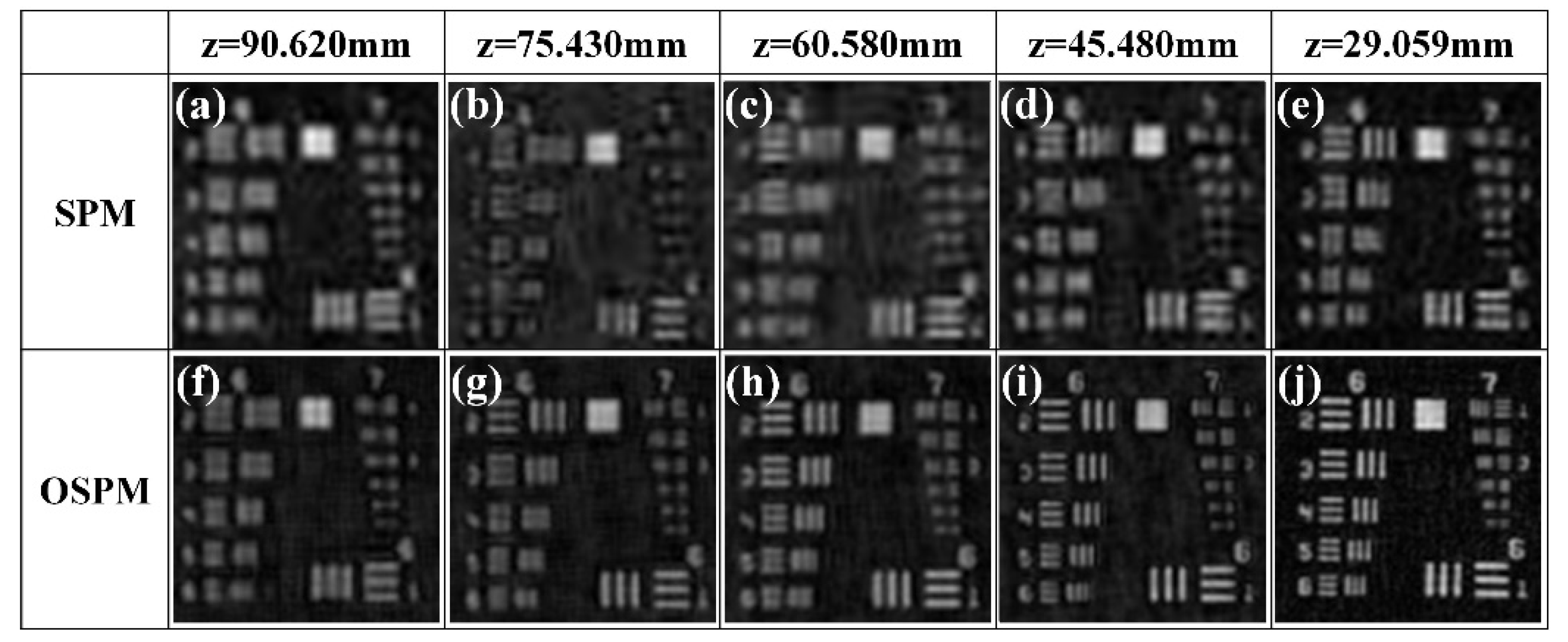
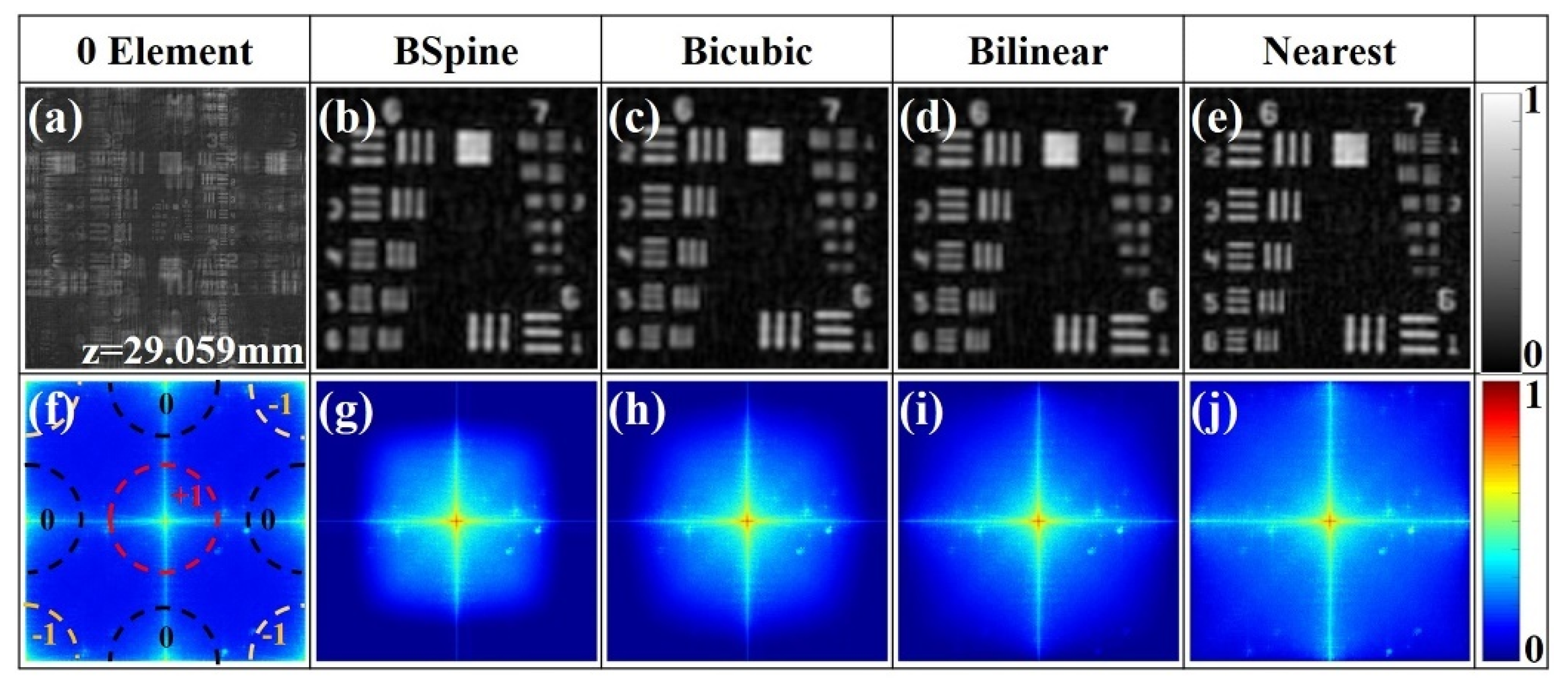
3. Results and Discussion

The proposed OSPM was verified experimentally based on the PPSDH system shown in Figure 1. A negative test target USAF1951 (Thorlabs R1DS1N) was used as a recording object. The central 2048 × 2048 pixels of the FLIR polarization camera based on the IMX250MZR sensor were used for hologram recording. Figure 4a–e show the reconstructed enlarged amplitude images obtained using the conventional SPM, and Figure 4f–j show those obtained using the proposed OSPM at different recording distances z.
Among them, the reconstructed image resolutions by the SPM and OSPM are 1024 × 1024 and 2048 × 2048, respectively, while the lateral spatial resolution of the reconstructed images increases with decreasing z. The critical distances z beyond where the lateral resolution of the SPM and OSPM is limited by the sampling interval are 77 mm and 38.5 mm in the case of B x = B S P x and B x = B O S P M x , respectively. The maximum lateral spatial resolution of the reconstructed images at recording distance z = 29.059 mm corresponds to group 6 element 3 (80.6-line pairs/mm, 12.4 µm) and group 7 element 1 (128.0-line pairs/mm, 7.8 µm) of the target. Thus, the proposed OSPM can simultaneously improve the image resolution and the maximum lateral spatial resolution of the reconstructed image.
Figure 5 shows the magnified amplitude images and Fourier spectral images of the normalized reconstructed images of the hologram with z = 29.059 mm, obtained using the HIM for comparing the effects of the interpolation algorithms. From the bottom to the top of Table 1, the sizes of the interpolation kernels are reduced from 11 × 11 to 1 × 1, and the attenuation effects of the corresponding low-pass filters on high-frequency information of the diffracted field o ( x , y ) are gradually weakened. Thus, the lateral resolutions of the reconstructed u ( x , y ) images based on B-spline, bicubic, bilinear, and nearest-neighbor interpolation are gradually improved, corresponding to group 6 element 4 (11.4 µm), element 5 (9.8 µm), and element 6 (8.8 µm), and group 7 element 1 (7.8 µm) of the target, respectively. However, the reconstructed image with zero interpolation is seriously degraded by the residual zero-order and twin-image noise. Thus, the proposed OSPM implemented by nearest-neighbor interpolation has the highest spatial lateral resolution of 7.8 µm.
The maximum lateral resolution of the proposed OSPM is more than the theoretical resolution of 2 = 6.9 µm, which may be an inherent error introduced by super-pixels. Figure 6 compares the reconstructed images of PSDH and PPSDH by numerical simulation. The simulation target was the processed reconstructed image of the R1DS1N with z = 29.059 mm, and the simulated pixel pitch was 3.45 µm, corresponding to group 7 element 2 (6.9 µm). The simulation results were in good agreement with the experimental results shown in Figure 5. Group 7 element 2 can be resolved in PSDH reconstructed images, but not in PPSDH, which is influenced by the residual zero-order and twin images in PPSDH.
The analysis of the above experimental results is mainly aimed at the target reconstructed image with z = 29.059 mm, which can highlight the differences between the proposed OSPM and SPM, between interpolation methods, and between PSDH and PPSDH. Our experimental results prove that the proposed OSPM can effectively improve the maximum imaging lateral resolution for PPSDH compared with the traditional SPM. In the OSPM, the nearest-neighbor interpolation with the smallest kernel size is used, which can retain more of the high-frequency information of the object while suppressing the residual zero-order and twin-image noise. Compared with classical interpolation methods, such as bilinear interpolation, the lateral resolution of the reconstructed image of OSPM can reach up to 7.8 µm.
The failure to achieve the ideal resolution of 6.9 µm that can be obtained by PSDH may be an inherent problem of PPSDH, caused by the residual zero-order and twin-image noise in Figure 5f. When the phase in the complex-valued test target that is different from the intensity modulation of USAF1951 changes drastically, the high-frequency information contained in the +1 order and −1 order images of the target is very strong. Since the frequency center of the −1 order image is located at the vertex of the spectrum rectangle, its strong high-frequency information is reflected in the low-frequency region, resulting in degradation of the reconstructed +1 order image. Therefore, the residual noise removal of PPSDH is one of the main problems to be solved in the future [39], and considering new sub-phase-shift hologram interpolation methods [17,40] or the interdependence between the four sub-phase-shift holograms [28,29] will be helpful to solve the above residual noise problem in PPSDH.
In addition, as shown in Figure 4, when the recording distance z is gradually reduced, the bandwidth B x of the diffracted light field at the detector plane is also gradually reduced, and the requirement for the sampling bandwidth of the sensor is also reduced accordingly. When B x B S P x ( z     77 mm), the OSPM and SPM will have similar spatial resolution, and an interpolation method with a larger kernel size can be used to reduce the root-mean-square error of the reconstructed image [30].

4. Conclusions

In this study, we propose an oversampled super-pixel image reconstruction method that can approximately achieve pixel resolution imaging, and the main reason for not reaching the ideal value is the inherent residual zero-order and twin-image noise of PPSDH. Compared with the existing image reconstruction methods in PPSDH, the proposed technique can retain more high-frequency information of +1 order images of the target, while suppressing the low-frequency components of the residual noise. However, the strong high-frequency components of the target may still lead to serious degradation of the reconstructed image quality; thus, the removal method of residual noise needs further research in the future.

Author Contributions

Conceptualization, Y.W., H.M., and X.L.; investigation, Y.W. and X.C.; validation, Y.W. and J.L.; writing—review and editing, Y.W.; funding acquisition, H.M. and X.L. All authors have read and agreed to the published version of the manuscript.

Funding

This research was funded by the Strategic Pilot Science and Technology Project (Class A) of the Chinese Academy of Sciences applied by Professor Haoran Meng, funding number XDA22020402.

Institutional Review Board Statement

Not applicable.

Informed Consent Statement

Not applicable.

Data Availability Statement

Not applicable.

Conflicts of Interest

The authors declare no conflict of interest.

References

  1. Fratz, M.; Seyler, T.; Bertz, A.; Carl, D. Digital holography in production: An overview. Light. Adv. Manuf. 2021, 2, 283–295. [Google Scholar] [CrossRef]
  2. Nayak, A.R.; Malkiel, E.; McFarland, M.N.; Twardowski, M.S.; Sullivan, J.M. A Review of Holography in the Aquatic Sciences: In situ Characterization of Particles, Plankton, and Small Scale Biophysical Interactions. Front. Mar. Sci. 2021, 7, 1256. [Google Scholar] [CrossRef]
  3. Nadeau, J.L.; Bedrossian, M.; Lindensmith, C.A. Imaging technologies and strategies for detection of extant extraterrestrial microorganisms. Adv. Phys. X 2018, 3, 1424032. [Google Scholar] [CrossRef] [Green Version]
  4. Javidi, B.; Carnicer, A.; Anand, A.; Barbastathis, G.; Chen, W.; Ferraro, P.; Goodman, J.; Horisaki, R.; Khare, K.; Kujawinska, M.; et al. Roadmap on digital holography [Invited]. Opt. Express 2021, 29, 35078–35118. [Google Scholar] [CrossRef]
  5. Yamaguchi, I.; Zhang, T. Phase-shifting digital holography. Opt. Lett. 1997, 22, 1268–1270. [Google Scholar] [CrossRef]
  6. Stoykova, E.; Kang, H.; Park, J. Twin-image problem in digital holography-a survey. Chin. Opt. Lett. 2014, 12, 060013. [Google Scholar] [CrossRef]
  7. Kimbrough, B.T. Pixelated mask spatial carrier phase shifting interferometry algorithms and associated errors. Appl. Opt. 2006, 45, 4554–4562. [Google Scholar] [CrossRef] [Green Version]
  8. Xia, P.; Ri, S.; Wang, Q.; Tsuda, H. Nanometer-order thermal deformation measurement by a calibrated phase-shifting digital holography system. Opt. Express 2018, 26, 12594–12604. [Google Scholar] [CrossRef]
  9. Awatsuji, Y.; Sasada, M.; Kubota, T. Parallel quasi-phase-shifting digital holography. Appl. Phys. Lett. 2004, 85, 1069–1071. [Google Scholar] [CrossRef]
  10. Xia, P.; Awatsuji, Y.; Matoba, O. One million fps phase measurement by digital holography. In Proceedings of the Selected Papers from the 31st International Congress on High-Speed Imaging and Photonics, Osaka, Japan, 7–10 November 2016; p. 103280K. [Google Scholar]
  11. Awatsuji, Y.; Koyama, T.; Tahara, T.; Ito, K.; Shimozato, Y.; Kaneko, A.; Nishio, K.; Ura, S.; Kubota, T.; Matoba, O. Parallel optical-path-length-shifting digital holography. Appl. Opt. 2009, 48, H160–H167. [Google Scholar] [CrossRef]
  12. Nomura, T.; Murata, S.; Nitanai, E.; Numata, T. Phase-shifting digital holography with a phase difference between orthogonal polarizations. Appl. Opt. 2006, 45, 4873–4877. [Google Scholar] [CrossRef] [PubMed]
  13. Tahara, T.; Awatsuji, Y.; Kaneko, A.; Koyama, T.; Nishio, K.; Ura, S.; Kubota, T.; Matoba, O. Parallel two-step phase-shifting digital holography using polarization. Opt. Rev. 2010, 17, 108–113. [Google Scholar] [CrossRef]
  14. Awatsuji, Y.; Fukuda, T.; Wang, Y.X.; Xia, P.; Kakue, T.; Nishio, K.; Matoba, O. 3D motion picture of transparent gas flow by parallel phase-shifting digital holography. In Proceedings of the Third International Conference on Photonics Solutions, Pattaya, Thailand, 8–10 November 2017; SPIE-Int Soc Optical Engineering: Bellingham, UK, 2018; Volume 10714. [Google Scholar]
  15. Meiling, Z.; Peng, G.; Kai, W.; Kequn, Z.; Yang, W.; Lixin, L.; Junwei, M.; Baoli, Y. A Comprehensive Review on Parallel Phase-shifting Digital Holography. Acta Photonica Sin. 2021, 50, 1. [Google Scholar]
  16. Millerd, J.; Brock, N.; Hayes, J.; North-Morris, M.; Kimbrough, B.; Wyant, J. Pixelated Phase-Mask Dynamic Interferometers. In Fringe 2005; Springer: Berlin/Heidelberg, Germany, 2006; pp. 640–647. [Google Scholar] [CrossRef]
  17. Mihoubi, S.; Lapray, P.-J.; Bigué, L. Survey of Demosaicking Methods for Polarization Filter Array Images. Sensors 2018, 18, 3688. [Google Scholar] [CrossRef] [Green Version]
  18. Rebhan, D.; Rosenberger, M.; Notni, G. Principle investigations on polarization image sensors. In Proceedings of the Photonics and Education in Measurement Science 2019, Jena, Germany, 17–19 September 2019; p. 111440A. [Google Scholar]
  19. Yamazaki, T.; Maruyama, Y.; Uesaka, Y.; Nakamura, M.; Matoba, Y.; Terada, T.; Komori, K.; Ohba, Y.; Arakawa, S.; Hirasawa, Y.; et al. Four-directional pixel-wise polarization CMOS image sensor using air-gap wire grid on 2.5-μm back-illuminated pixels. In Proceedings of the 2016 IEEE International Electron Devices Meeting (IEDM), San Francisco, CA, USA, 3–7 December 2016; pp. 8.7.1–8.7.4. [Google Scholar] [CrossRef]
  20. Tahara, T.; Ito, K.; Fujii, M.; Kakue, T.; Shimozato, Y.; Awatsuji, Y.; Nishio, K.; Ura, S.; Kubota, T.; Matoba, O. Experimental demonstration of parallel two-step phase-shifting digital holography. Opt. Express 2010, 18, 18975–18980. [Google Scholar] [CrossRef]
  21. Brock, N.J.; Crandall, C.; Millerd, J.E. Snap-shot imaging polarimeter: Performance and applications. In Polarization: Measurement, Analysis, and Remote Sensing XI.; SPIE: Bellingham, WA, USA, 2014; p. 909903. [Google Scholar] [CrossRef]
  22. Jiao, S.; Zou, W. High-resolution parallel phase-shifting digital holography using a low-resolution phase-shifting array device based on image inpainting. Opt. Lett. 2017, 42, 482–485. [Google Scholar] [CrossRef]
  23. Tahara, T.; Kanno, T.; Arai, Y.; Ozawa, T. Single-shot phase-shifting incoherent digital holography. J. Opt. 2017, 19, 065705. [Google Scholar] [CrossRef]
  24. Liang, D.; Zhang, Q.; Wang, J.; Liu, J. Single-shot Fresnel incoherent digital holography based on geometric phase lens. J. Mod. Opt. 2019, 67, 92–98. [Google Scholar] [CrossRef] [Green Version]
  25. Tahara, T.; Ito, T.; Ichihashi, Y.; Oi, R. Single-shot incoherent color digital holographic microscopy system with static polarization-sensitive optical elements. J. Opt. 2020, 22, 105702. [Google Scholar] [CrossRef]
  26. Tsuruta, M.; Fukuyama, T.; Tahara, T.; Takaki, Y. Fast Image Reconstruction Technique for Parallel Phase-Shifting Digital Holography. Appl. Sci. 2021, 11, 11343. [Google Scholar] [CrossRef]
  27. Liu, H.; V, V.R.; Ren, H.; Du, X.; Chen, Z.; Pu, J. Single-Shot On-Axis Fizeau Polarization Phase-Shifting Digital Holography for Complex-Valued Dynamic Object Imaging. Photonics 2022, 9, 126. [Google Scholar] [CrossRef]
  28. Liu, S.; Chen, J.; Xun, Y.; Zhao, X.; Chang, C.-H. A New Polarization Image Demosaicking Algorithm by Exploiting Inter-Channel Correlations with Guided Filtering. IEEE Trans. Image Process. 2020, 29, 7076–7089. [Google Scholar] [CrossRef]
  29. Xie, F.; Chen, J. A Demosaicing Algorithm Based on Local Directional Gradients for Polarization Image. In Proceedings of the 2021 International Conference on Computing, Networking, Telecommunications & Engineering Sciences Applications (CoNTESA), Tirana, Albania, 9–10 December 2021; pp. 40–44. [Google Scholar] [CrossRef]
  30. Xia, P.; Tahara, T.; Kakue, T.; Awatsuji, Y.; Nishio, K.; Ura, S.; Kubota, T.; Matoba, O. Performance comparison of bilinear interpolation, bicubic interpolation, and B-spline interpolation in parallel phase-shifting digital holography. Opt. Rev. 2013, 20, 193–197. [Google Scholar] [CrossRef]
  31. Zhaoxiang, J. Pixelated Polarization Imaging Technique and Its Application in Digital Holographic Microscopy. Ph.D. Thesis, University of Science and Technology of China, Anhui, China, 2020. [Google Scholar]
  32. Lane, C.; Rode, D.; Rösgen, T. Calibration of a polarization image sensor and investigation of influencing factors. Appl. Opt. 2021, 61, C37–C45. [Google Scholar] [CrossRef] [PubMed]
  33. Wenhui, Z.; Liangcai, C.; Guofan, J. Review on high resolution and large field of view digital holography. Infrared Laser Eng. 2019, 48, 603008. [Google Scholar] [CrossRef]
  34. Gao, P.; Yuan, C. Resolution enhancement of digital holographic microscopy via synthetic aperture: A review. Light. Adv. Manuf. 2022, 3, 105–120. [Google Scholar] [CrossRef]
  35. Liu, X.; Liu, X.; Zhang, H.; Fan, Y.; Meng, H. Research progress of digital holography in deep-sea in situ detection. In Proceedings of the Seventh Symposium on Novel Photoelectronic Detection Technology and Applications, Kunming, China, 5–7 November 2021; p. 117636J. [Google Scholar]
  36. LUCID VISION LABS. Available online: http://thinklucid.cn/tech-briefs/polarization-explained-sony-polarized-sensor (accessed on 5 April 2022).
  37. Latychevskaia, T.; Fink, H.-W. Practical algorithms for simulation and reconstruction of digital in-line holograms. Appl. Opt. 2015, 54, 2424–2434. [Google Scholar] [CrossRef] [Green Version]
  38. Tahara, T.; Ito, K.; Kakue, T.; Fujii, M.; Shimozato, Y.; Awatsuji, Y.; Nishio, K.; Ura, S.; Kubota, T.; Matoba, O. Parallel phase-shifting digital holographic microscopy. Biomed. Opt. Express 2010, 1, 610–616. [Google Scholar] [CrossRef]
  39. Tahara, T.; Shimozato, Y.; Xia, P.; Ito, Y.; Awatsuji, Y.; Nishio, K.; Ura, S.; Matoba, O.; Kubota, T. Algorithm for reconstructing wide space-bandwidth information in parallel two-step phase-shifting digital holography. Opt. Express 2012, 20, 19806–19814. [Google Scholar] [CrossRef]
  40. Kocsis, P.; Shevkunov, I.; Katkovnik, V.; Rekola, H.; Egiazarian, K. Single-shot pixel super-resolution phase imaging by wavefront separation approach. Opt. Express 2021, 29, 43662–43678. [Google Scholar] [CrossRef]
Figure 1. Experimental geometry of PPSDH. He–Ne laser: helium–neon laser source; P: polarizer; SF: spatial filter assembly: MO: microscope objective, Pi: pinhole, CL: collimating lens; M: mirror; HWP: half-wave plate; PBS: polarizing beam splitter; BS: non-polarizing beam splitter; QWP: quarter-wave plate; PPC: pixelated polarization camera.
Applsci 12 05812 g001
Figure 2. Conventional super-pixel method (SPM) calculation procedure of image reconstruction for PPSDH. SMH: spatially multiplexed hologram; PS: phase-shifting technique; ASM: angular spectrum method.
Applsci 12 05812 g002
Figure 3. Proposed oversampled super-pixel method (OSPM) for PPSDH: (a) schematic diagram and (b) calculation procedure.
Applsci 12 05812 g003
Figure 4. Reconstructed enlarged amplitude images using (ae) the conventional SPM and (fj) proposed OSPM at different recording distances z.
Applsci 12 05812 g004
Figure 5. Magnified amplitude images and spectral images of the normalized reconstructed images obtained using the HIM when the interpolation algorithms were (a,f) 0 element, (b,g) B-spline, (c,h) bicubic, (d,i) bilinear, and (e,j) nearest-neighbor.
Applsci 12 05812 g005
Figure 6. The simulated normalized reconstructed images of target with z = 29.059 mm by PSDH and PPSDH: (ad) amplitude images and (eh) Fourier spectral images of the original simulation target, PSDH, 0 element, and nearest-neighbor interpolation of PPSDH, respectively.
Applsci 12 05812 g006
Table 1. The classical convolutional interpolation kernels [31].
Method Kernel   Function   f ( x , y ) = h h T Size
0 elements h = (   1   ) T 1 × 1
Nearest-neighbor h = (   1   1   ) T 2 × 2
Bilinear h = (   1 2   1   1 2   ) T 3 × 3
Bicubic h = ( 1 16   0   9 16   1   9 16   0 1 16   ) T 7 × 7
B-spline h = ( 3 152   0 9 76   0   91 152   1   91 152   0 9 76   0 3 152 ) T 11 × 11
Publisher’s Note: MDPI stays neutral with regard to jurisdictional claims in published maps and institutional affiliations.

