1. Introduction
There has been an increasing demand for flexible production systems that can produce individualized and customized products to meet diverse needs in recent years. For example, the German government has defined such flexible production systems as “smart factories” and is promoting Industry 4.0 to realize them [
1]. To realize these smart factories, a higher level of automation is required.
One of the technologies required for advanced automation is the autonomous transportation of raw materials, products, etc. within an industrial plant, known as internal transport. Conventional internal transport often uses affixed equipment, such as conveyor belts. Changing production lines that use affixed equipment requires considerable additional investment and effort, making it difficult to realize a flexible production system.
In recent years, there have been reports of the use of mobile robots to achieve more flexible internal transport [
2,
3]. Various forms of mobile robot platforms have been proposed, including wheeled robots [
4], quadrupedal [
5] and bipedal robots [
6]. Leg-type robots are capable of stable transportation on uneven terrain. However, in-house transport is often performed on paved roads, so wheeled robots with high motion efficiency are often employed. In particular, omnidirectional wheeled robots are often preferred for this due to their high maneuverability [
7], with various mechanisms already proposed in literature [
8].
In general, either omni wheels or mecanum wheels achieve omnidirectional movement. An omni wheel is a wheel with freewheel rollers on a plane perpendicular to its axis of rotation. By sliding in a direction parallel to its rotation axis, omnidirectional movement is achieved. On the other hand, a mecanum wheel uses freewheel rollers that continuously contact the wheel and the floor. As a result, mecanum wheels have the disadvantage of causing the robot to be prone to vibration because the contact point with the floor moves in the direction of the axis of rotation [
9]. Due to this issue, we use omni wheels rather than mecanum wheels in this work.
The smaller the factory’s footprint, the better and more compact equipment is preferred. The same applies to mobile robots for internal transport. “Compact” is defined as “having a dense structure or parts or units closely packed or joined” [
10]. In this work, we consider a robot to be compact if its structure and components leave little dead space. Our design policy is based on this idea. Robots built under the conditions that make them compact have a different wheel arrangement than conventional ones, so their control characteristics may differ. Therefore, special attention is paid to the effects of control errors in the operating characteristics due to intrinsic factors. It is not easy to control a system perfectly to follow the target control volume as internal and external factors influence its operation. It is even more complicated when the cost is a factor, such as in industrial applications. The effect on noise caused by imperfection of control is described as sensitivity to noise. To evaluate the sensitivity to intrinsic factors, we compare and discuss the trajectories of robots using a conventional wheel arrangement and our proposed arrangement, maintaining the same testing conditions. This way, the effect of external factors remains constant and observed differences can be mostly attributed to intrinsic factors.
To our knowledge, this is the first work that proposed a design methodology for an omni wheel robot that focuses on compactness, as well as verification of its sensitive to noise.
The contribution of our paper is as follows:
From the viewpoint of dead space and kinematics, we propose a design methodology for compact omnidirectional robots.
Through experimental validation, we demonstrate the feasibility of our approach and analyze the effects of wheel placement when following different trajectories.
Moreover, our experimental results show that by using our proposed arrangement, robots are more compact and have lower tracking errors (especially travel direction) and travel time when following straight trajectories, which are the most commonly utilized in factories. These results suggest that the proposed arrangement provides better performance in addition to spatial advantages in the design of robots used in factories.
The remainder of this paper is organized as follows.
Section 2 summarizes recent research on wheel placement and control methods for omni wheel robots.
Section 3 explains the conditions for a compact omni wheel arrangement, taking into account dead space and kinematics in omni wheel robots.
Section 4 describes the specifications and experimental conditions of the robot that we built for motion evaluation and summarizes the experimental results. Finally,
Section 5 summarizes the design method of the compact omni wheel robot and its sensitivity to noise as a summary of the previous explanations.
2. Related Work
There have been numerous studies on the design of omni wheel mobile robots. Shabalina et al. compare the characteristics of various mobile robots, including omni wheel robots [
11]. Kanjanawanishkul discusses the movement mechanism of omnidirectional mobile robots and mentions the kinematics of omni wheel robots in [
12]. A common consideration among most of these previous studies is that the omni wheel’s axes of rotation point toward the center of the robot. Although Wang et al. present kinematic equations for omni wheel mobile robots that do not have to follow this assumption, they still only validate them for a robot in which the axes point toward its center [
13]. The restriction of omni wheel orientation also restricts the placement of actuators and other robot components, which affects its compactness. In this work, by not limiting the direction of the omni wheel, we achieve a compact design that would not be otherwise achievable.
However, by not limiting the orientation of the omni wheels, the sensitivity to noise, tracking errors, and vibrations caused by each wheel’s rotation may be different from that of a conventional wheel arrangement (wheels axis pointing toward the center of the robot). Hence, it is vital to compare the newly designed wheel arrangement’s sensitivity to those of a conventional robot. Loh et al. showed that a three-axis omni wheel robot has no singularity [
14]. Because the robot designed in this study has different kinematics, it is necessary to reexamine the presence or absence of singularities. Path-following performance is also essential in evaluating the sensitivity to noise. To validate this, a platform is developed. To control the speed of the platform motors, a simple controller needs to be implemented. PID control is a popular method for speed control [
15,
16]; the difficulty lies in finding adequate parameters. Wang et al. and Pang et al. proposed a path-following method using model predictive control (MPC) [
13,
17]. However, MPC consumes a great amount of computational resources, making it impractical. Instead, we used a linear quadratic regulator (LQR) in this work. An LQR can find optimal control parameters for a multi-input, multi-output system in which the robot speed is used as input, and the speed of each actuator is used as output. This paper introduces a control method for omni wheel robots using LQR and compares path-following performance.
3. Compact Omni Wheel Robot Design
Regarding the location where wheels are placed, to maximize stability, it is desirable to have four wheels [
18] and to have wheels at the four corners of the robot.
Then, it is necessary to determine the angle at which motors are placed. It is common practice to have the actuators placed so the wheels axes of rotation point toward the center of the robot [
13,
14,
19,
20,
21,
22]. However, it is essential to note that motors divide the space inside the robot where other components can be placed. Therefore, motors become obstacles to part placement, affecting how compact the robot can become. As will be proved later, the common practice of placing actuators pointing toward the robot’s center does not lead to compact designs.
3.1. Condition about Wheel Arrangement
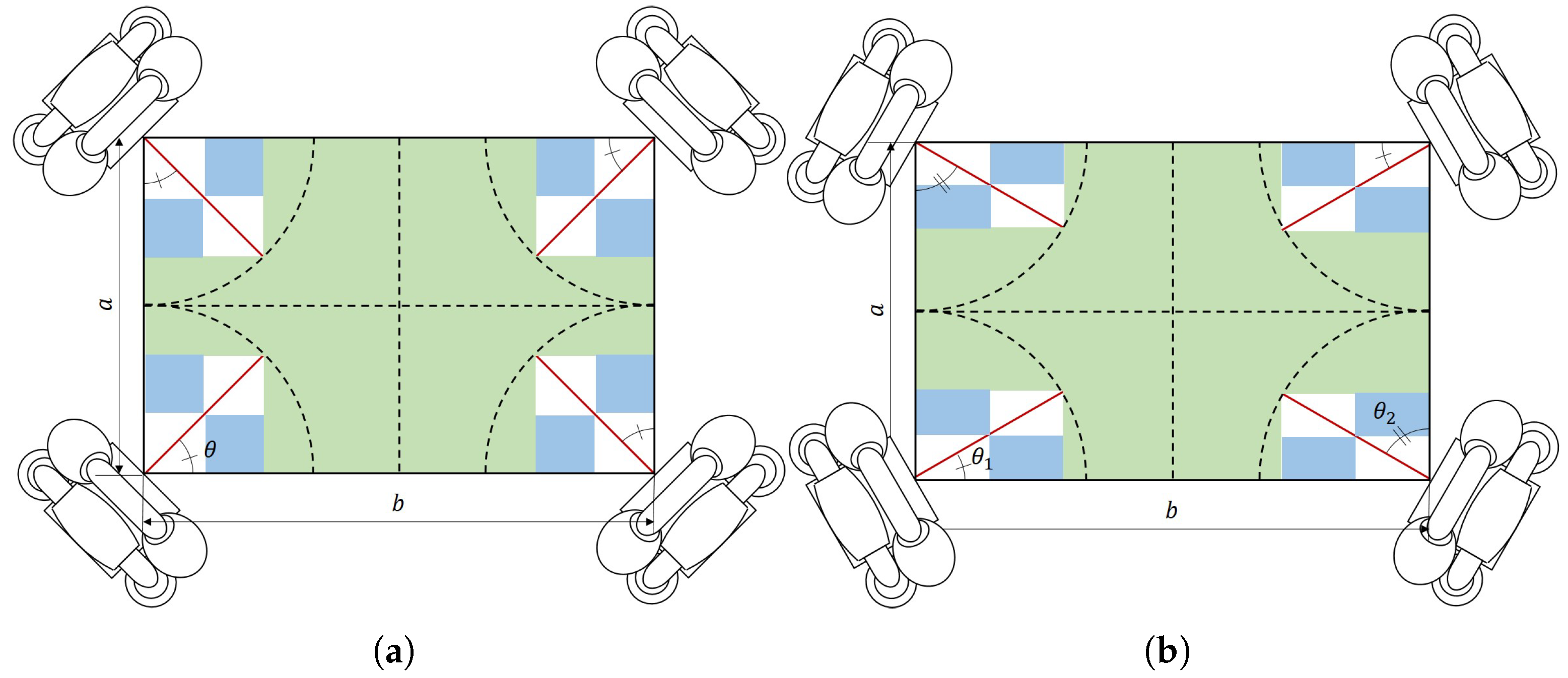
Figure 1 shows two different motor arrangements to illustrate the difference in available space given the angle at which motors (red lines) are placed.
To find the most compact configuration, we need to identify the angles at which the available space is maximized. To simplify the problem, we consider dividing the robot into four identical areas by dividing the robot at the midpoint of its length (b) and width (a); consider that the length of the actuators is and its thickness 0. Then, since most of the parts on the robot, such as batteries, compute modules, sensors, etc. are rectangular, we try to maximize the area where rectangular parts can be placed.
Under these assumptions, the available areas where parts can be placed are (i) the rectangular portions divided by the actuator (light blue areas) and (ii) the remaining green area where actuators do not interfere.
To calculate (i), we know that the area of the largest rectangle inscribed in a triangle is half that of the triangle. Therefore, the total area (
) of the parts that can be placed in the rectangular areas (8 different areas) divided by the actuator is
To calculate (ii), we compute the rectangular portion not divided by the actuator
, which results in
Therefore, the total area
s where rectangular parts can be placed can be obtained by the following equation
Since the range of the angle
between the circumference of the robot and the actuator is
, from Equation (
3), we find that the maximum area where rectangular parts can be placed is
for angles
or
.
Therefore, when fabricating a high-density omni wheel robot, we should consider placing actuators angled to the periphery of the robot.
3.2. Compact Omni Wheel Robot Kinematics
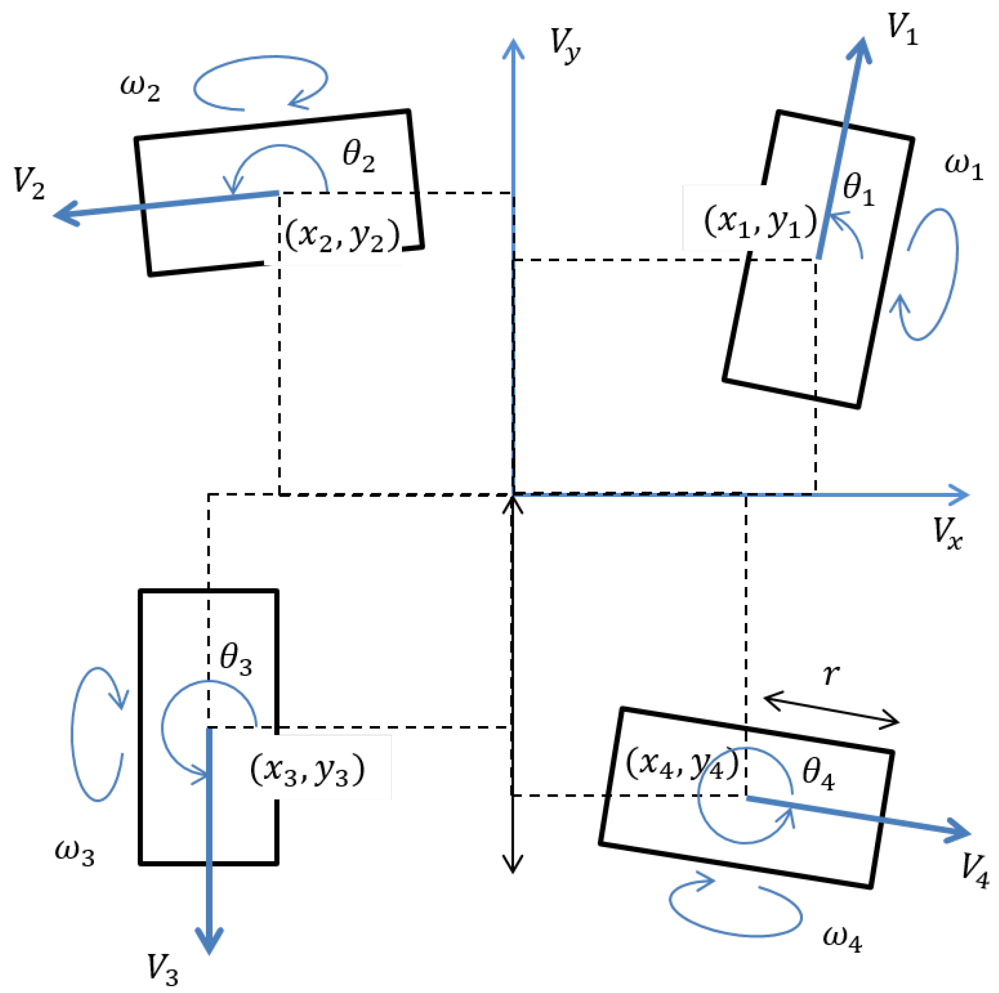
To properly control an omni wheel robot, it is necessary to find the relationship between the velocity and angular speed of the robot’s center of mass and its wheels’ rotational speed. That is, the robot’s kinematic and inverse kinematic equations.
For the robot’s stability, a four-wheel robot is selected.
Figure 2 shows the diagram of such a four-wheel robot.
Extending the kinematics equation proposed by Wang et al. [
13] for a three-wheel robot to a four-wheel robot, we have that
where
r and
are the radius and angular velocity of the omni wheel.
is the angle at which it is mounted.
and
are the distance and direction of the omni wheel with respect the robot’s center.
As shown in Equation (
4), in the case of a four-wheel robot, the kinematics matrix is not square, so the inverse kinematics cannot be obtained by inverting it. Instead, the pseudoinverse matrix is used to find the inverse kinematics as proposed in [
15,
16,
23].
Following the aforementioned method, the inverse kinematics equation is found to be
Each row of the Jacobi matrix T must be linearly independent if the matrix has the pseudoinverse matrix . Therefore, each omni wheel direction must be different. In other words, to realize a compact four omni wheel robot, wheels must be along the periphery, and adjacent wheels must be orthogonal to each other.
4. Motion Verification
To verify that the sensitivity to noise of our proposed compact omnidirectional robot is similar to that of a conventional one (whose motors point toward its center), we implemented a simple robot and compared its performance to that of a conventional omnidirectional robot. We also verified that the equations described in the previous section adequately describe its motion.
In the remainder of this section, we describe the implemented robot’s hardware configuration and control method and describe the methodology used for the experiment and its results.
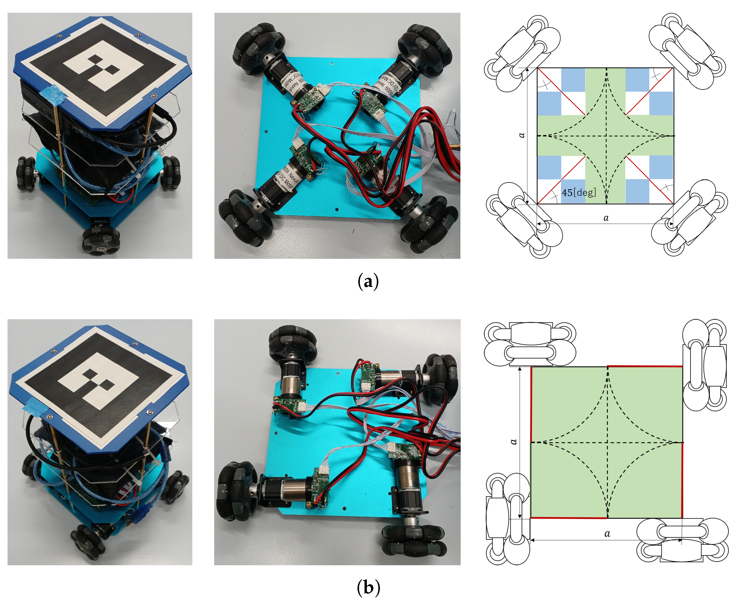
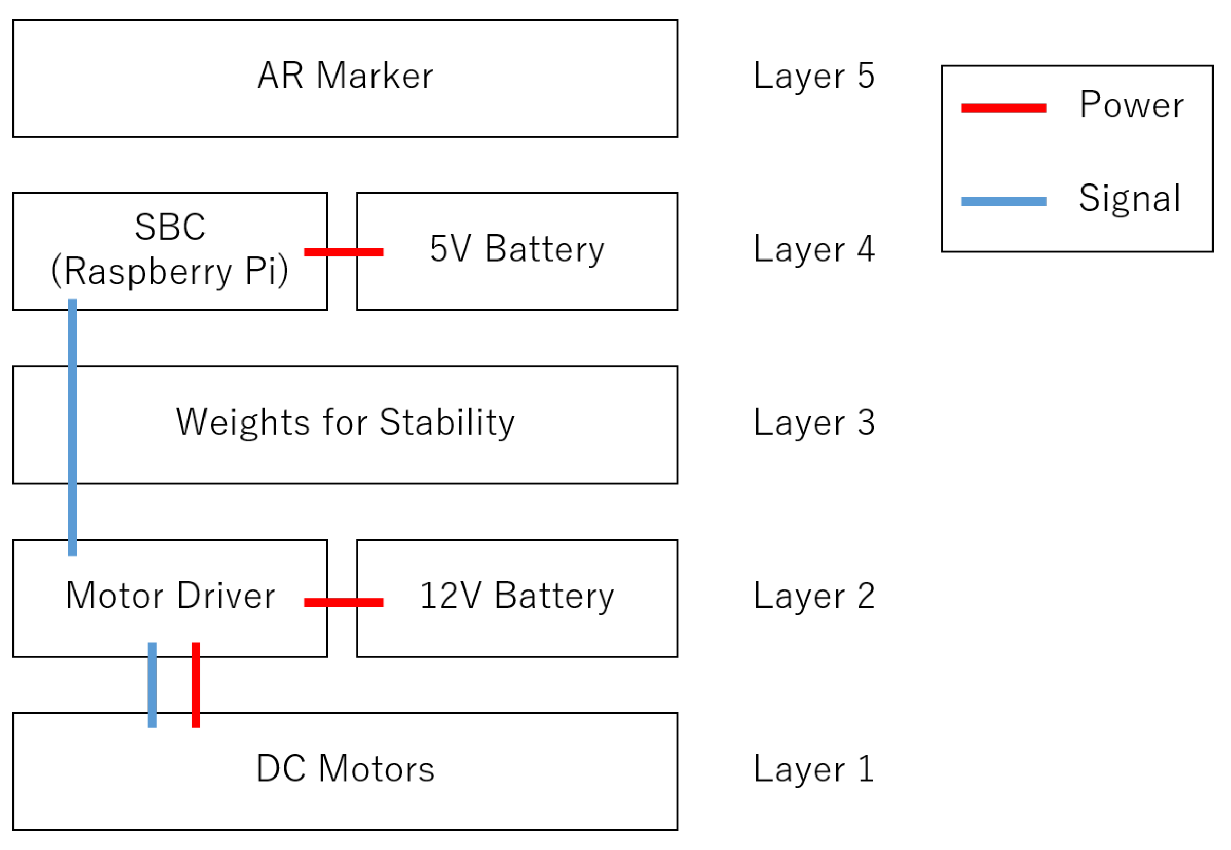
4.1. Hardware Configuration
In the bottom layer, the DC motors are located.
Figure 4 show the robot’s wheels configuration for the conventional and our proposed robot, respectively.
For this experiment, starting the second layer, the conventional and our proposed robot configuration do not change. In the second layer, the motor driver and its battery are located. The motor driver contains an Arduino-compliant microcontroller.
Since Kundu et al. have shown that the robot will be unstable if all four wheels are not grounded [
24], a 1.5 [kg] weight was placed on the third layer so that all four wheels are grounded.
In the fourth layer, a single-board computer (Raspberry Pi 4) and its battery are placed. The single board computer is used for motion control.
In the fifth layer, an augmented reality (AR) marker is placed. The AR marker is used to acquire the robot’s position during the motion verification experiment. The AR marker was generated by a Robot Operating System package (
http://wiki.ros.org/ar_track_alvar, accessed on 22 April 2022). ROS was also used to acquire the marker location during the experiment.
4.2. Control Method
To implement any model-based control method, we require the state-space equations that represent robot motion, as well as the model for our selected actuator (DC motors).
For this, using the model presented in [
25], we express the relationship between the motor’s torque load and its angular velocity as
where
is the torque load,
is the angular velocity,
E is the voltage applied,
R is the motor’s resistance, and
k is the torque constant. The torque
is proportional to each acceleration
with the moment of inertia
as a coefficient. Assuming that the moment of inertia
applied to the motor is constant for each motor, Equation (
6) can be transformed using the relationship between load torque and angular acceleration and Equation (
4).
where
.
When the robot is running at the desired speed,
, we have that
. Linear quadratic regulator (LQR) is a control regulator often used to solve problems formulated like this. LQR is a method that aims to minimize
where
and
are the state and the input of the system and
Q and
R are the weight matrix of the function. In this case,
is
, and
is
where
is the ideal voltages applied to each motors to move the robot at the target speed
. It is needed to solve the following Riccati equation for the evaluation function minimization.
where
,
and
Q and
R are the weight matrix; generally, with the identity matrix in the evaluation function,
P is a solution to the equation and is uniquely determined by
A,
B,
Q, and
R. Using the matrix
P satisfies this equation, the following equation expresses the voltages
E applied to each motor to move the robot.
4.3. Experimental Evaluation
To compare the performance of the robots with each configuration, the robots are tasked with following two different trajectories. The materials and conditions used in the experiments are listed in
Table 1. As mentioned before, trajectories are measured using AR markers attached to the top surface of the robot. Specifically, the robot’s position is measured by tracking the AR marker using a camera located 2 m above the ground. A Logitech C930 camera was selected for this purpose (
https://www.logicool.co.jp/ja-jp/products/webcams/c930e-business-webcam.960-001199.html, accessed on 22 April 2022). The measurements were taken every 200 ms.
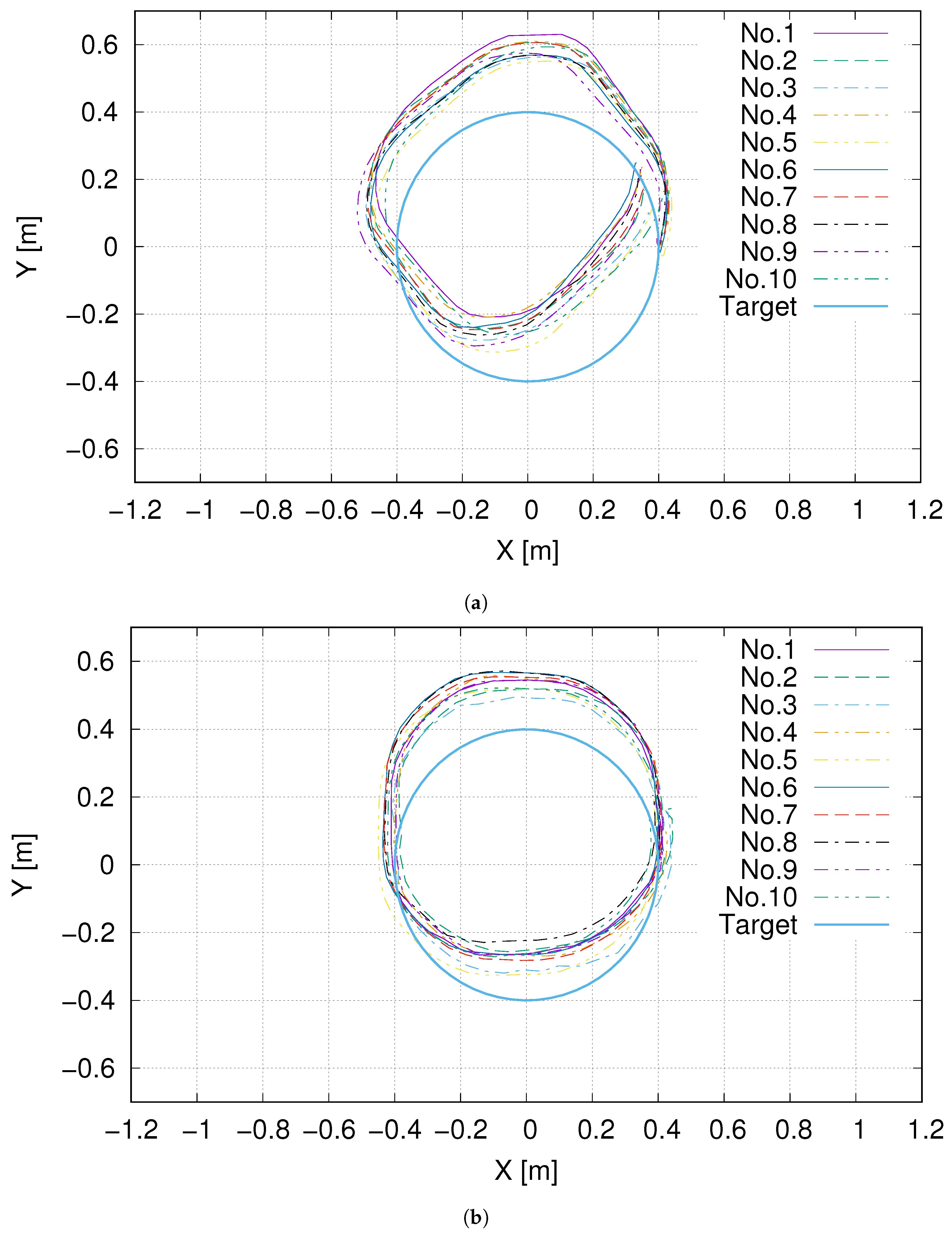
The selected trajectories are (i) a circle with a radius of 0.4 m and (ii) a square with a side of 0.8 m to evaluate the omnidirectional robot’s characteristic movement in all directions and the forward–backward and left–right trends often used in transport robots. The size of these paths was selected as to fit in the camera’s field of view. The front of the robot is assumed to be the x-axis positive direction, and the robot’s initial position is set to x-coordinate 0.4 and y-coordinate 0.0. The circle and square paths are centered at the center of coordinates.
4.4. Results
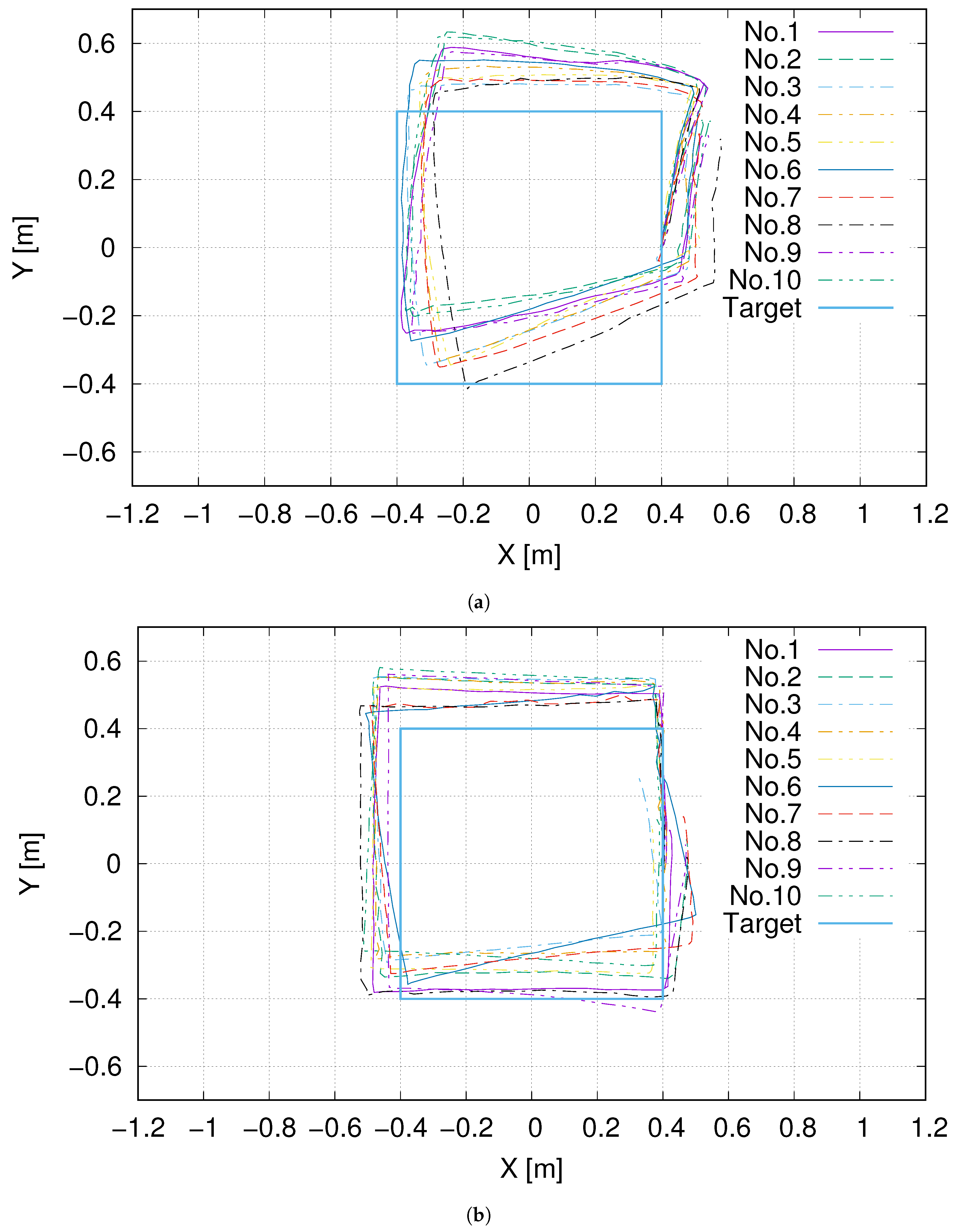
The traversed paths for each configuration and target trajectories are shown in
Figure 5 and
Figure 6.
From the experiment results, we can observe that the robots tend to prefer moving in the same direction as their wheels, making the shape of the trajectory different for both configurations. As it can be seen in
Figure 5, for the conventional robot, the path looks like a rhomboid, while for our proposed design, it looks like a square.
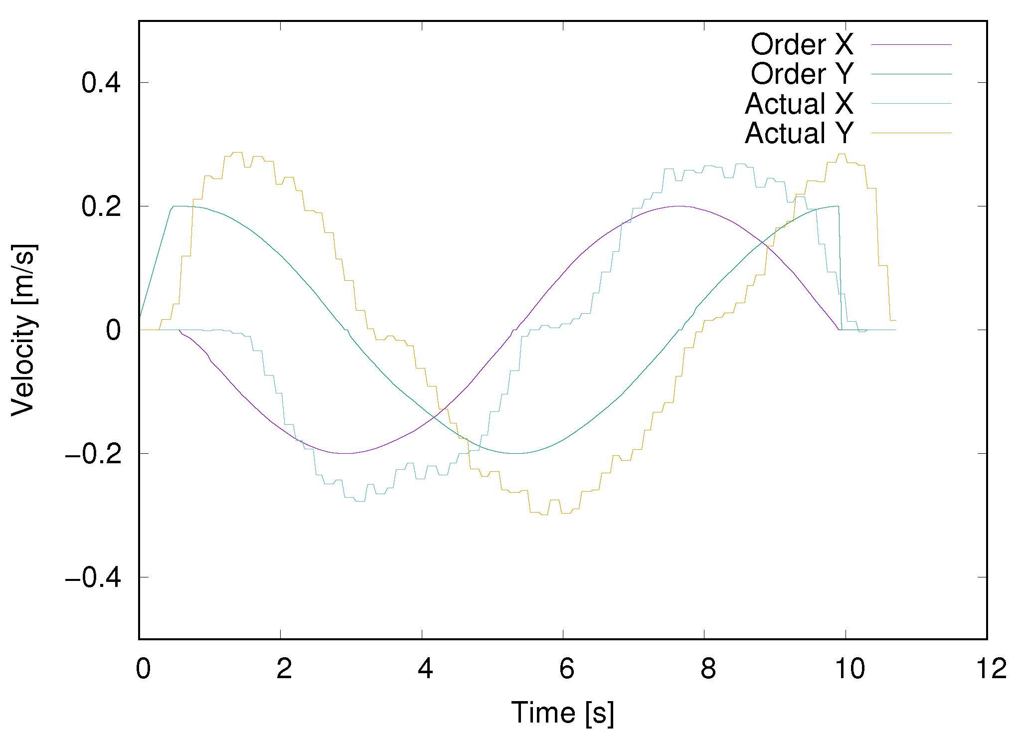
These results can be explained by the DC motors not being driven correctly at a slow speed. This is confirmed when looking at
Figure 7, which shows that the actual velocities of the robot do not follow target velocities accurately. This is a problem that can be mostly attributed to the controller; therefore, it can be stated that the LQR controller used does not suffice. As we are not interested in robot control but in understanding how the different configurations affect performance, we did not improve on this controller.
Instead, we focus on how wheel placement can affect trajectory control. While not due to an inherent mechanical design issue, these experiments prove that trajectory errors can result from poor control and mechanical design.
Finally, we evaluate the trajectory error by measuring the travel direction error between measured locations and their corresponding target locations.
The median is used because it correctly evaluates the direction the robot moves by excluding the effects of outliers caused by lagging control. To assess if the median errors for the conventional and proposed arrangements are statistically significant, we performed a two-tailed t-test, with a rejection probability of 5%.
For the circular pattern (
Table 1 and
Table 2), we have that the difference in median distance errors for both configurations was not significantly different (t = 1.7;
p < 0.106), while the difference in median angular errors was significant (t = 3.8;
p < 0.0013). This shows that our proposed arrangement can provide the movement with less postural blur than the conventional type.
For the square pattern (
Table 3 and
Table 4), we found significant differences in the distance errors (t =13.3;
p < 9.47 × 10
) and angular errors (t = 6.6;
p < 3.37 × 10
). Given these values, we can ascertain that for the square pattern, our proposed arrangement improved performance.
The time required to complete the trajectory for each robot configuration/test is shown in
Table 6. A two-tailed t-test with a rejection probability of 5% was applied to the time required for the two robots. We found significant differences in the time required for circle pattern (t = 6.5;
p < 4.11 × 10
) and square pattern (t = 13.1;
p < 1.2 × 10
). As a result of the above, the proposed arrangement has the potential to operate as accurately or more accurately as a conventional type and still operate at high speed.
5. Conclusions
Factories are required to reduce wasted space in order to lower costs. Therefore, mobile robots used in factories must be compact and have high maneuverability. This manuscript presented a methodology for designing compact omnidirectional mobile robots. In particular, omnidirectional mobile robots are equipped with omni wheels, which are less prone to vibrations than mecanum wheels. Omni wheel robots in prior studies are often designed, so their wheels’ axes of rotations point toward the center of the robot. However, restricting wheel placement also restricts the placement of other components, such as actuators, which may affect the system’s compactness. In this manuscript, we examined wheel arrangement without restricting the orientation of wheel axles. In terms of compactness, we showed that it is optimal to place the wheels so that the actuators are aligned with the robot’s perimeter.
To validate our proposed design, a comparison of the robot’s sensitivity to noise caused by each wheel’s rotation was made by having two robots, one with a compact wheel arrangement and one with a conventional wheel arrangement, move along two predetermined paths.
As a result of moving a circular path, the two robots were found to move along paths with different distortions. This distortion was attributed to an imperfection in the control of the LQR, which is that it cannot achieve a stable speed at low speeds. The different distortions exhibited suggest that the wheel arrangement changes the effect of imperfect control on the robot’s motion. When the robots traveled on a square pattern, the error of the proposed robot’s travel direction was smaller than the conventional type’s. This indicates that the proposed arrangement may be more effective in environments where the robot is often moved back and forth as well as left and right. The proposed arrangement is effective in factories because such movements are often performed in processes, as typified by internal transfers. Furthermore, the proposed arrangement travels more quickly in the two trajectories shows our approach is suitable for use in factories.


