
Designing Comprehensive Shifting Control Strategy of Hydro-Mechanical Continuously Variable Transmission

Abstract
:1. Introduction
1.1. Research on Influencing Factors of Shift Quality
1.2. Design and Research of Clutch Shift Controller
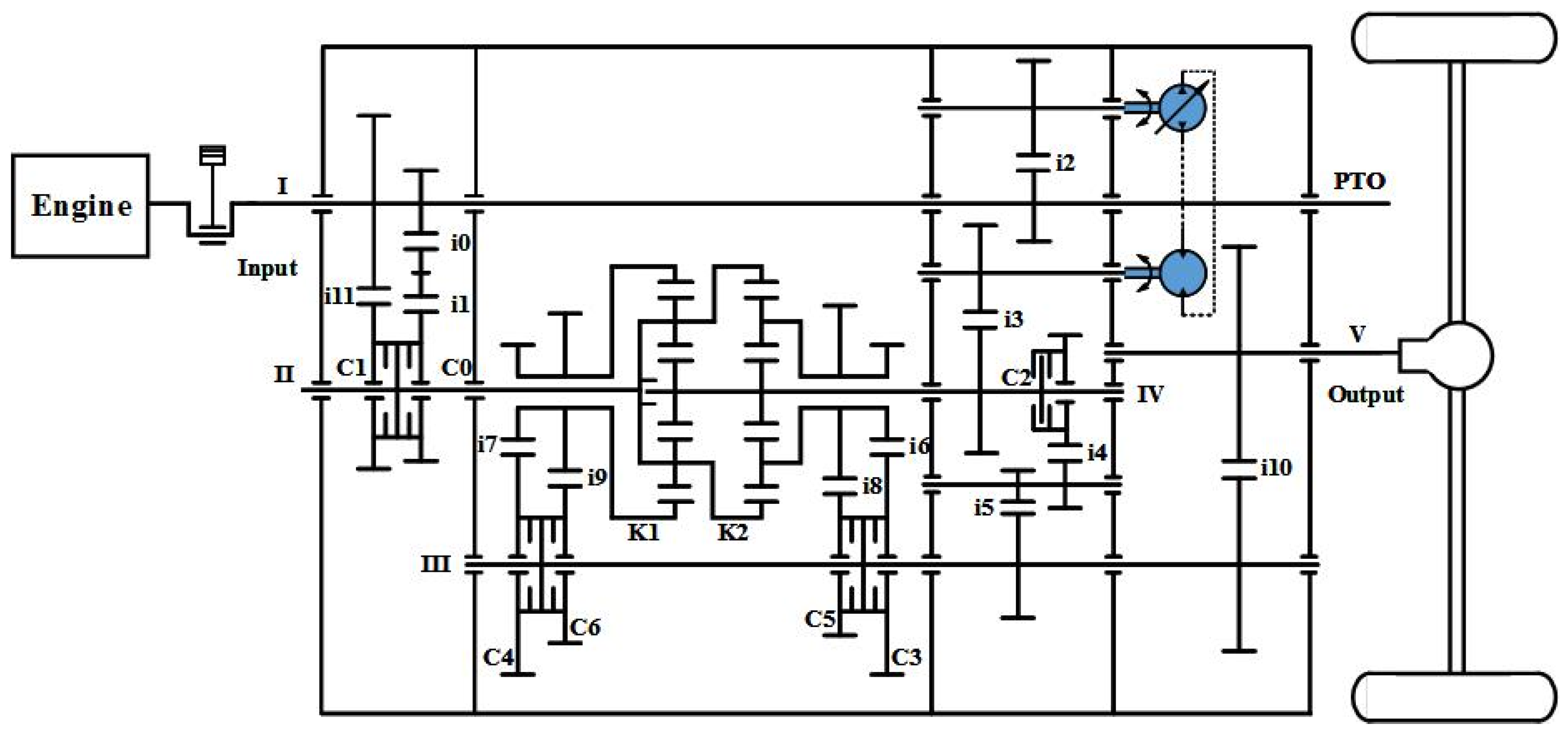
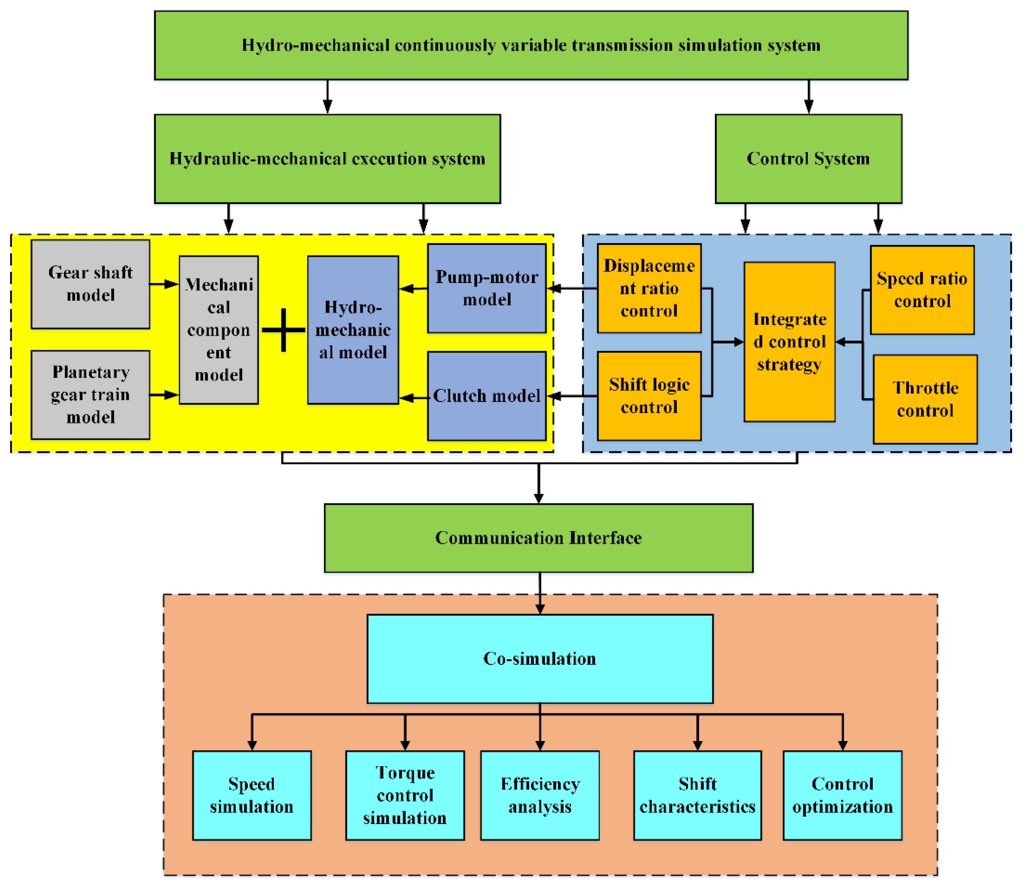
2. Mathematical Modeling and Methods
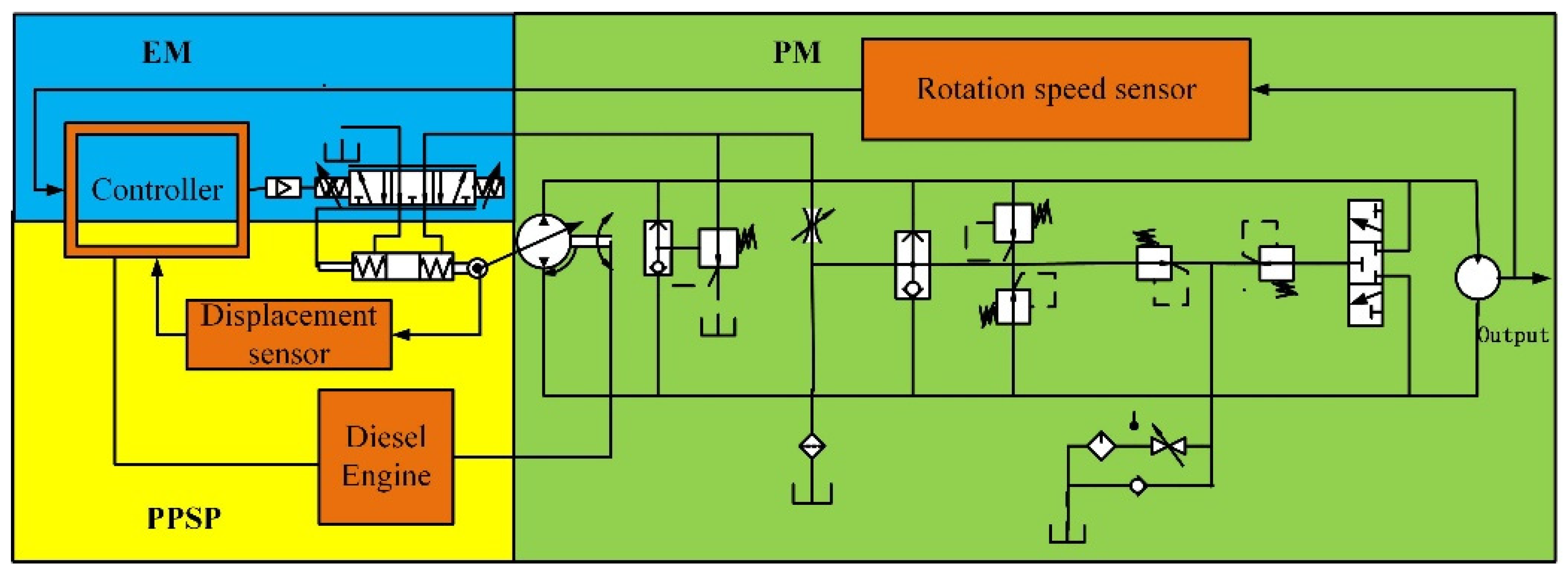
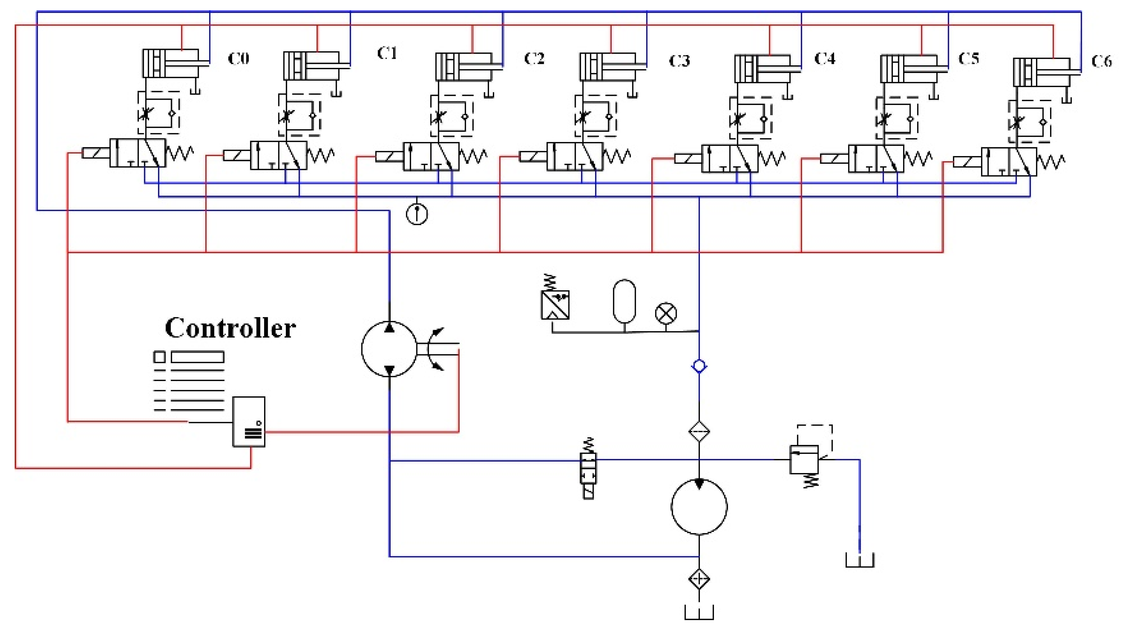
2.1. Pump-Motor Hydraulic System Model
2.1.1. Electro-Mechanical Conversion Unit
2.1.2. Control Unit of the Swash Plate Inclination
2.1.3. Piston-Swash Plate Inclination
2.1.4. Variable Pump-Fixed Motor System
2.1.5. Speed Sensor and Proportional Amplifier
2.2. Mathematical Model of Clutch System
2.2.1. Electro-Hydraulic Proportional Valve Model
2.2.2. Wet Clutch Model
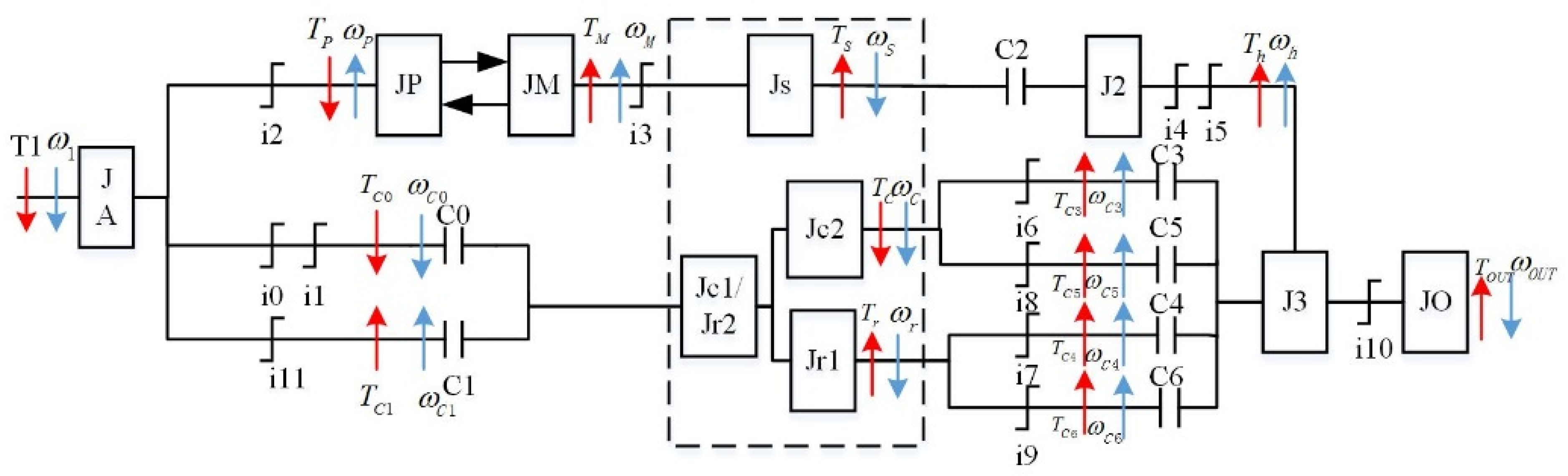
2.3. Transmission Shaft Model
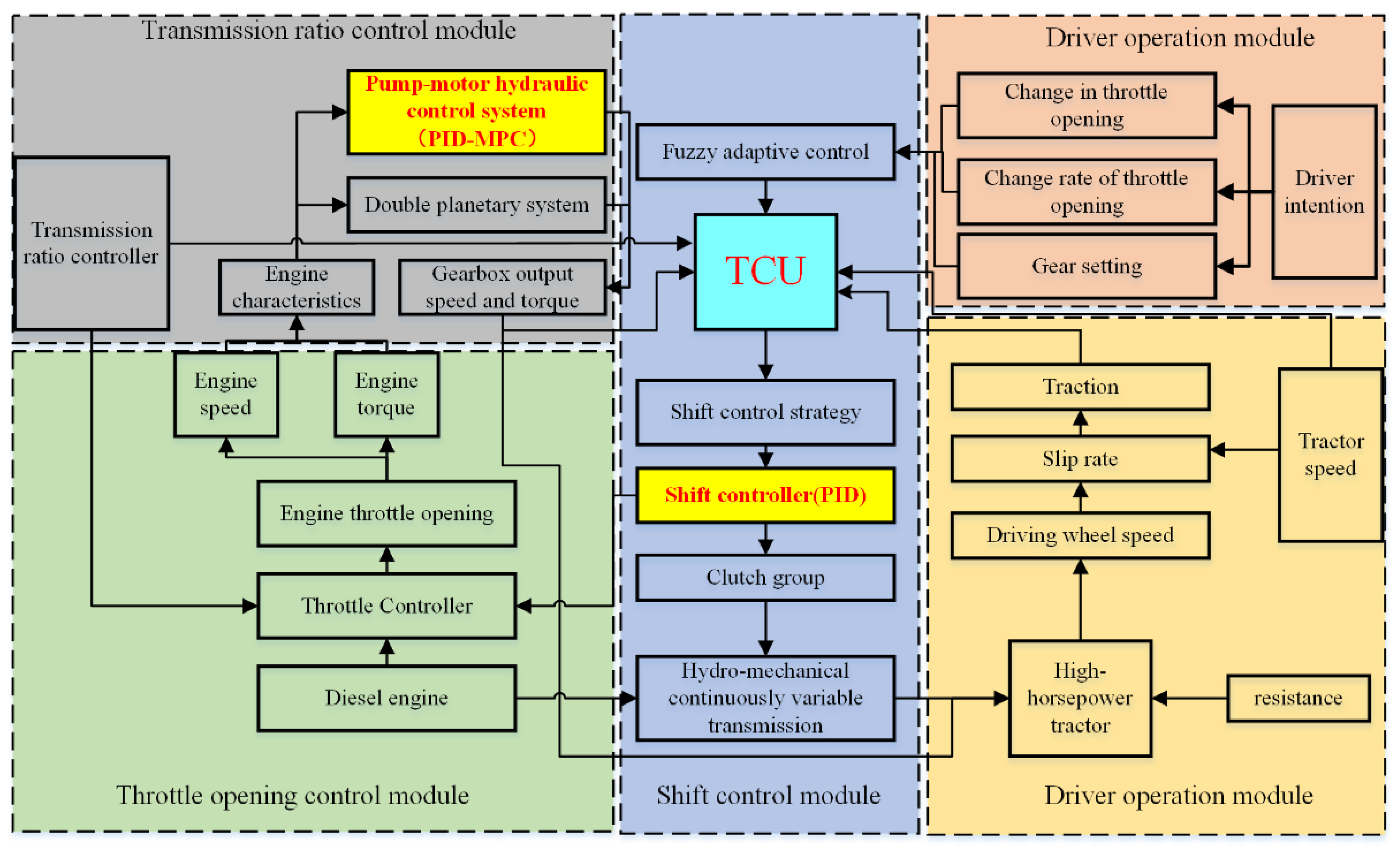
2.4. The Composition of the Control System
2.4.1. Design of Clutch Control System
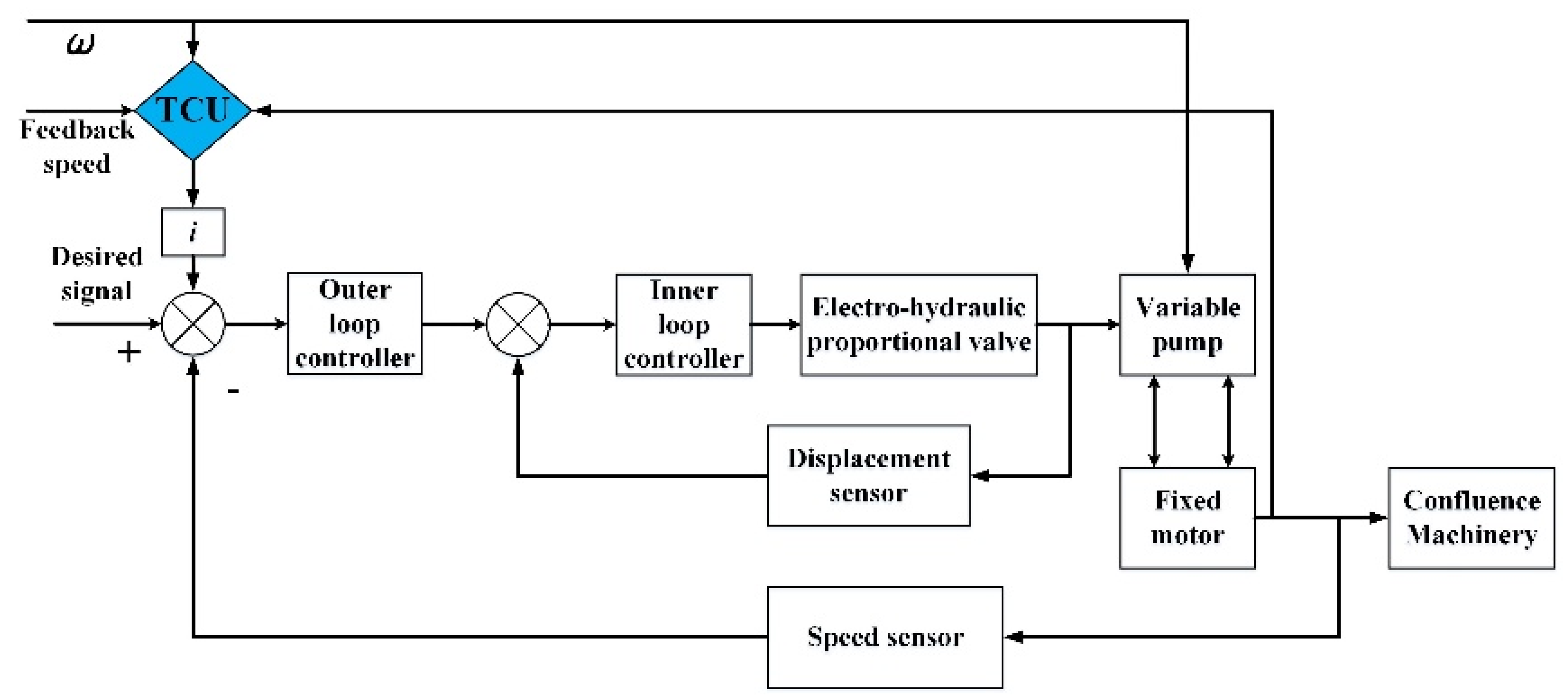
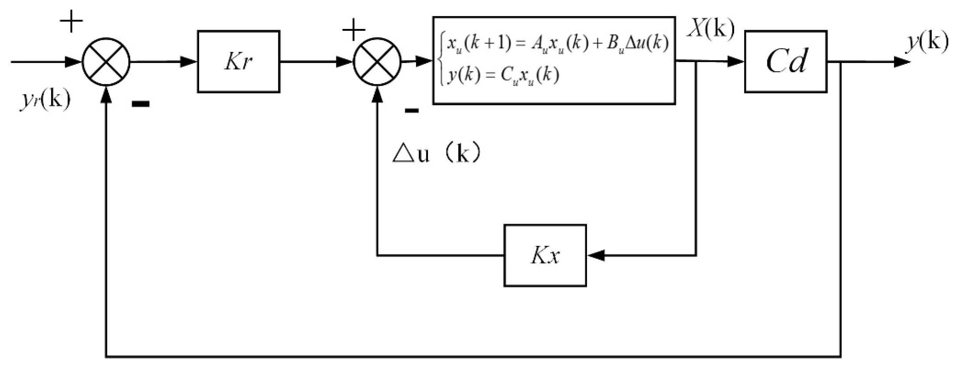
2.4.2. Pump-Motor Hydraulic System Control System
2.5. HMCVT Control Strategy
3. Results and Discussion
3.1. Test Verification of HMCVT
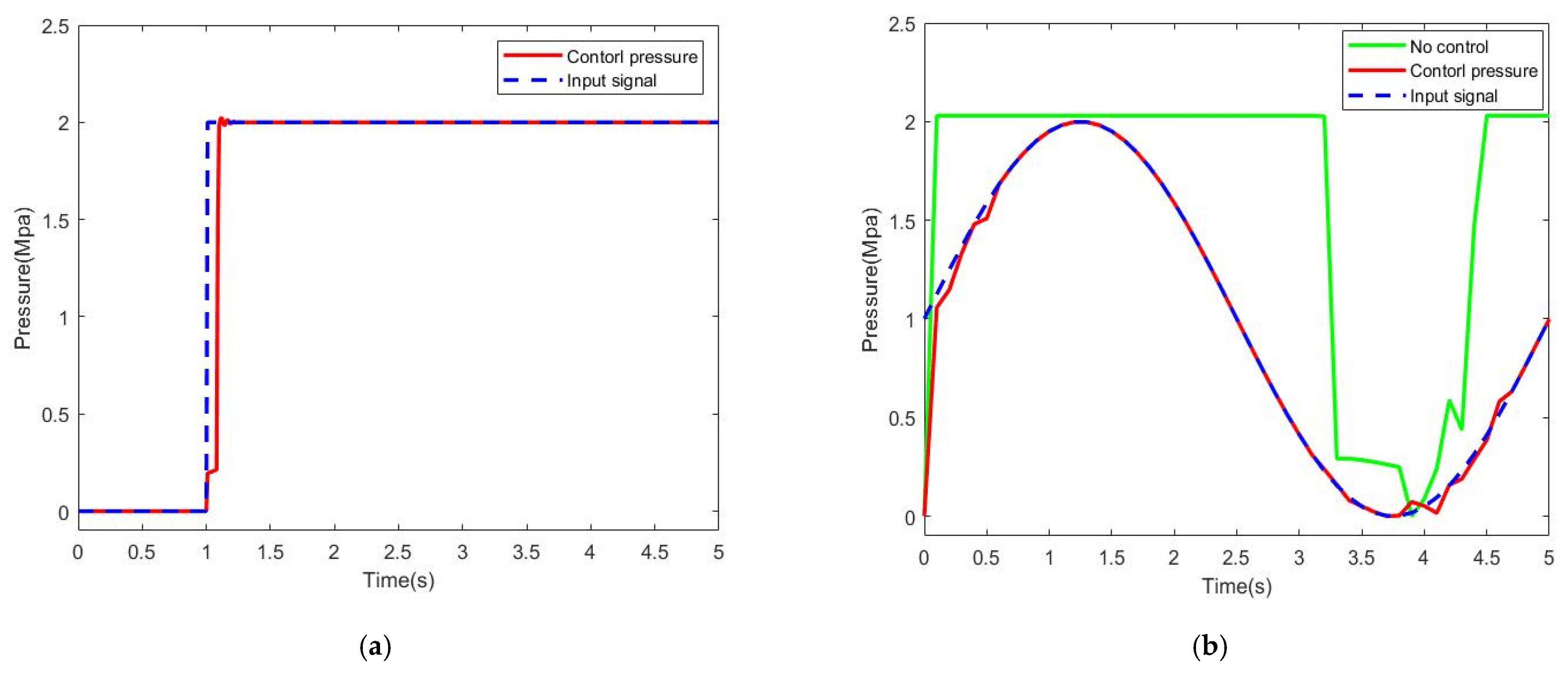
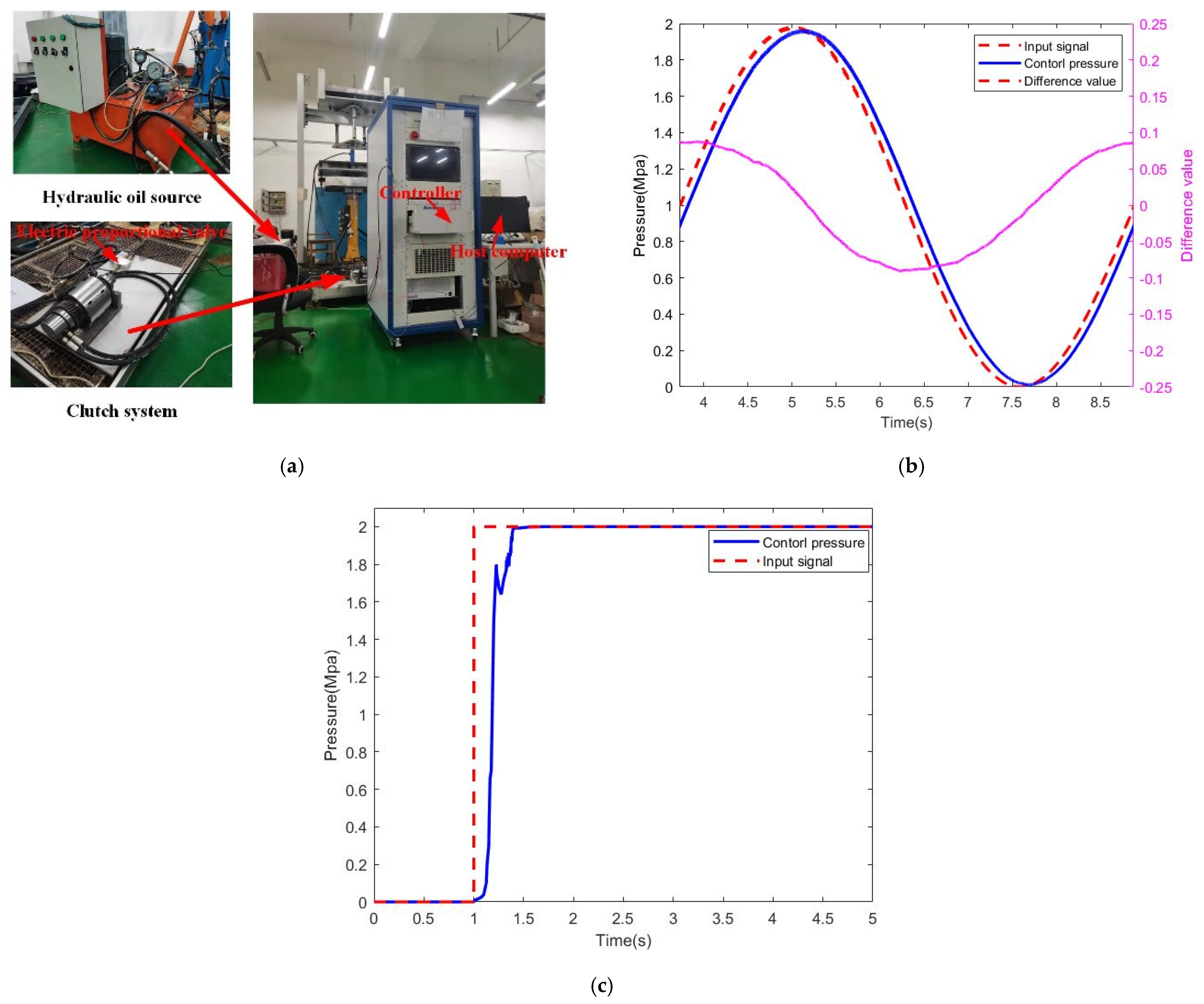
3.1.1. Test Verification of Clutch Control System
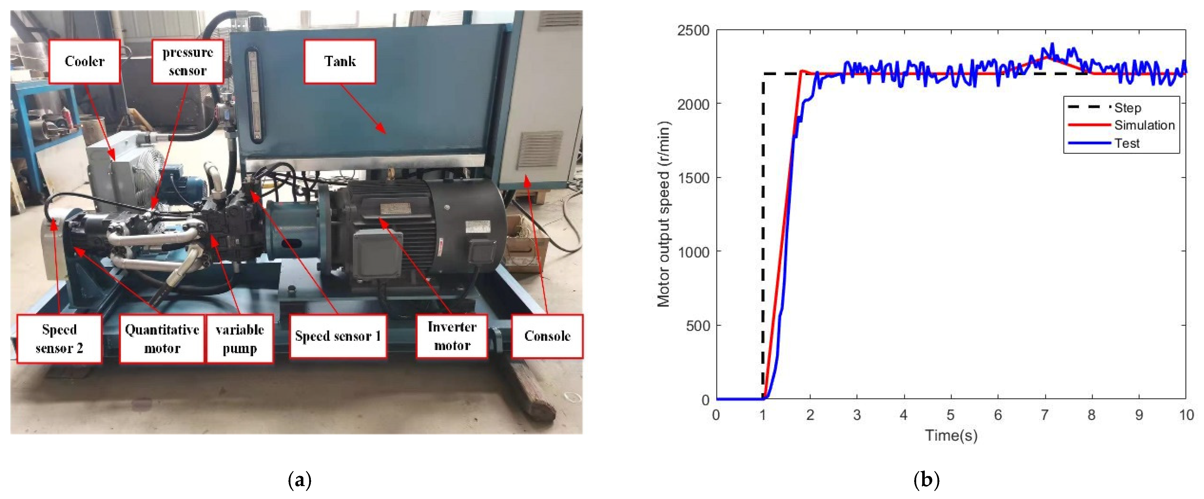
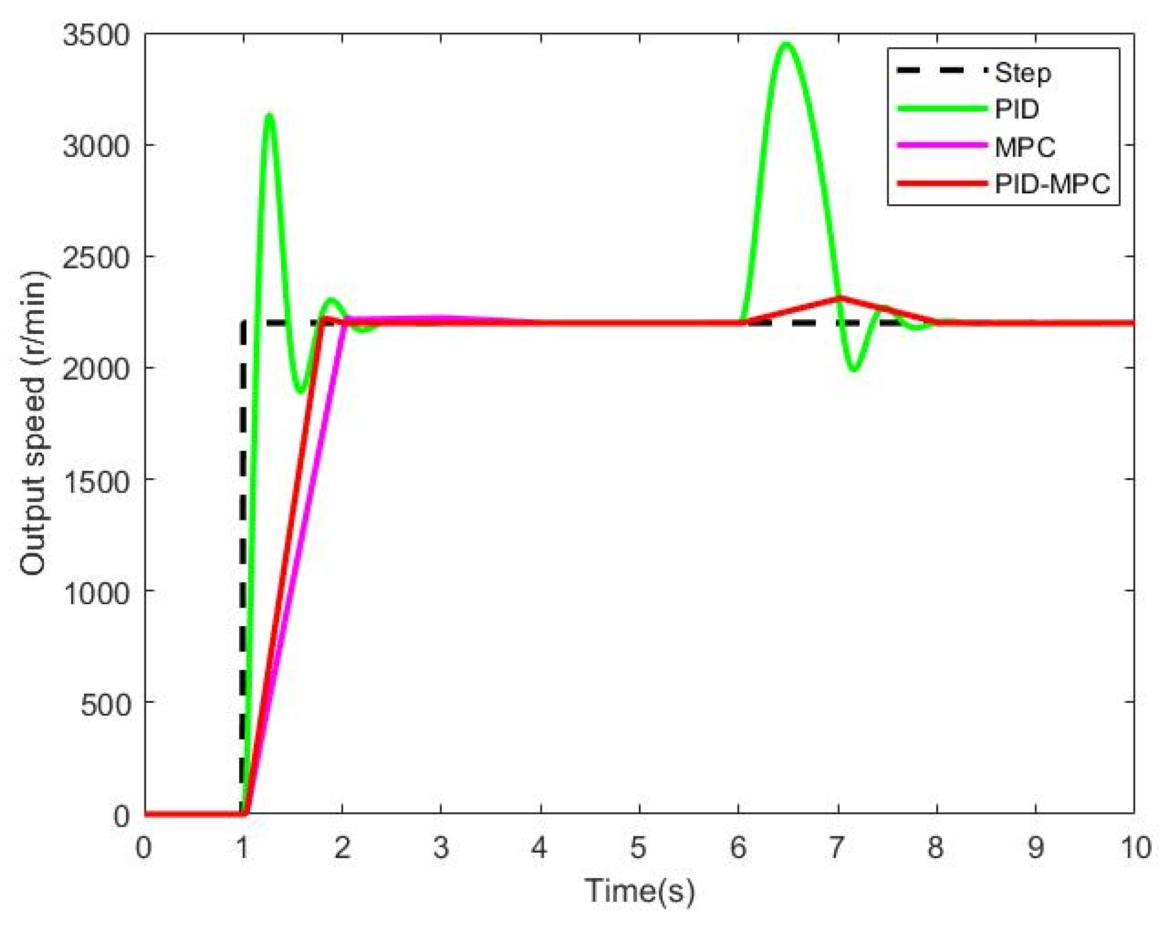
3.1.2. Test Verification of Variable Pump-Fixed Motor Control System
3.2. Shift Quality Evaluation Index
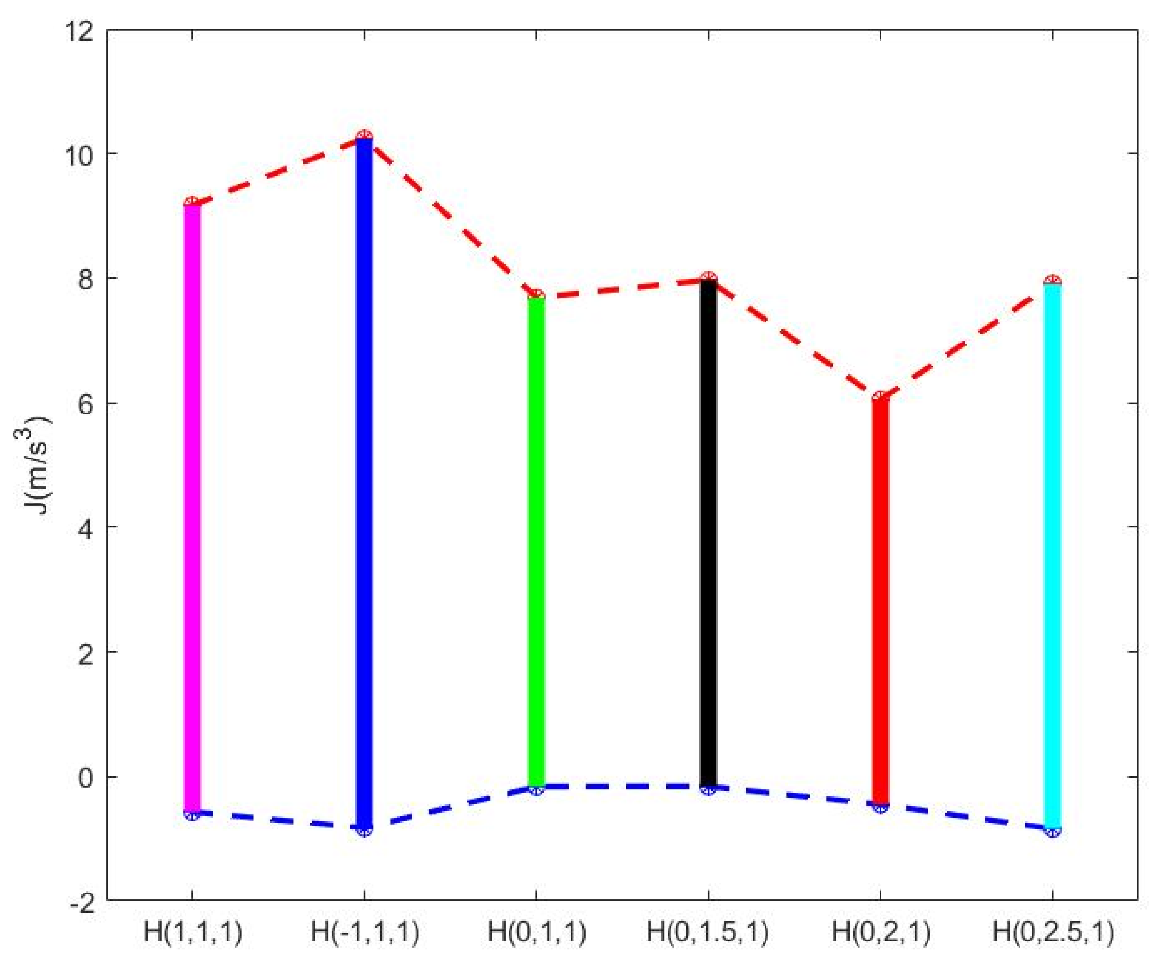
3.3. Definition of Control Strategy
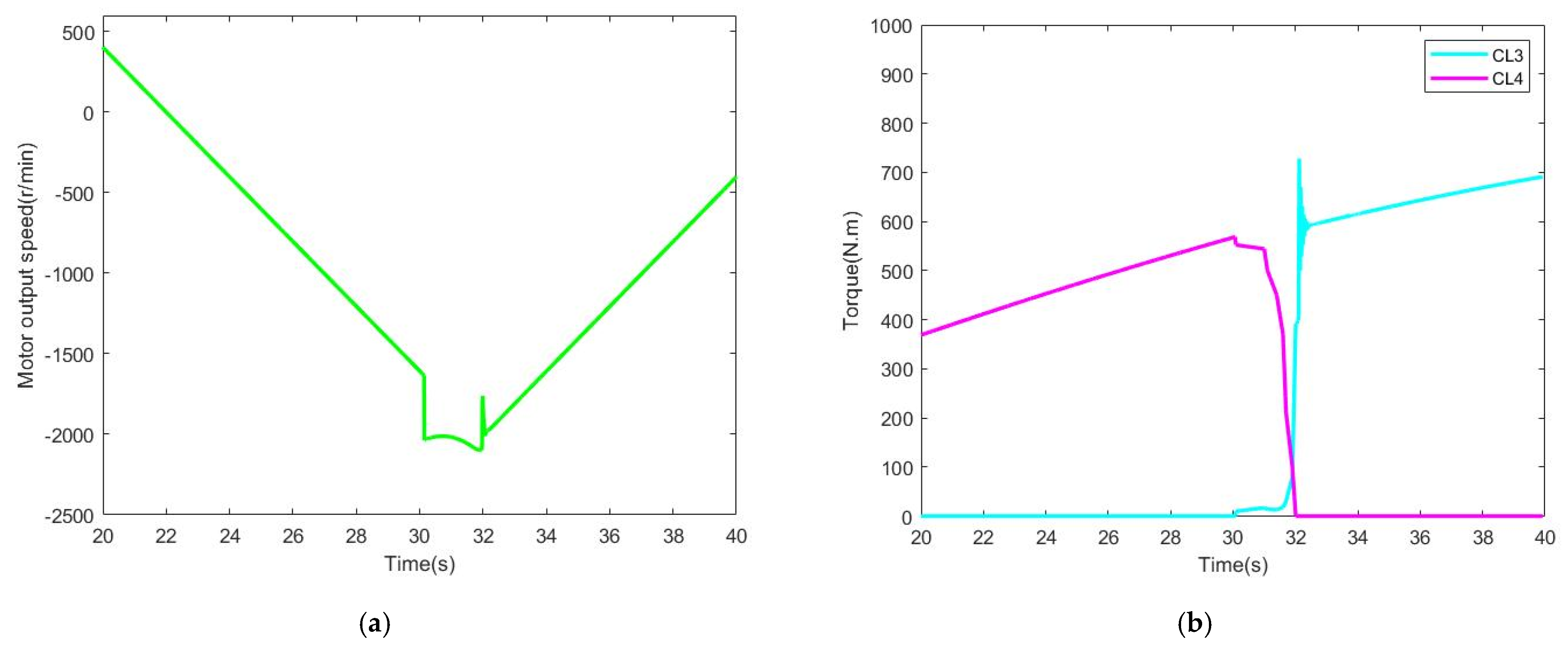
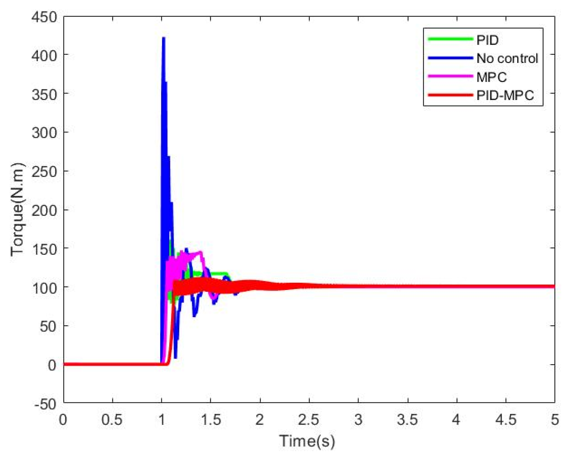
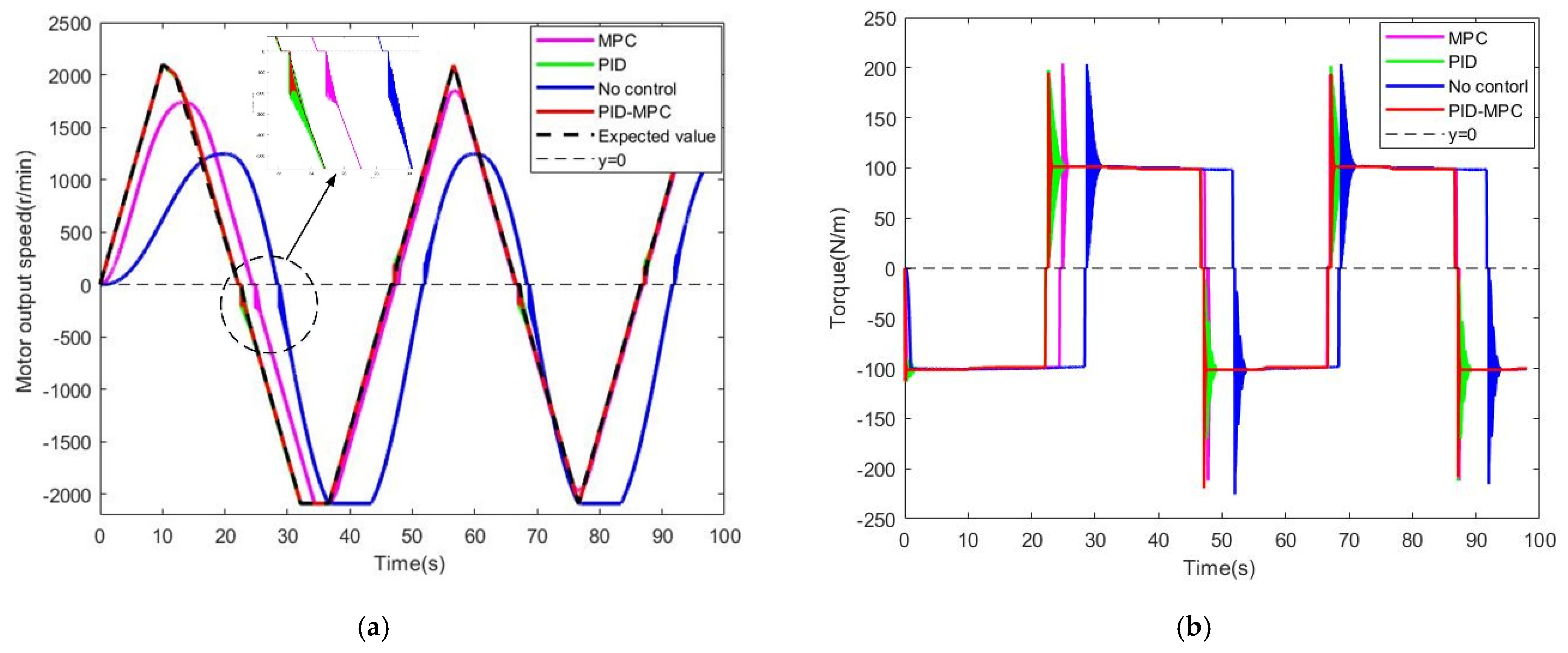
3.4. Simulation of Integrated Control Shift Control Strategy
4. Conclusions
Author Contributions
Funding
Institutional Review Board Statement
Informed Consent Statement
Data Availability Statement
Conflicts of Interest
References
- Rossetti, A.; Macor, A. Multi-objective optimization of hydro-mechanical power split transmissions. Mech. Mach. Theory 2013, 62, 112–128. [Google Scholar] [CrossRef]
- Cammalleri, M.; Rotella, D. Functional design of power-split CVTs: An uncoupled hierarchical optimized model. Mech. Mach. Theory 2017, 116, 294–309. [Google Scholar] [CrossRef]
- Xia, Y.; Sun, D. Characteristic analysis on a new hydromechanical continuously variable transmission system. Mech. Mach. Theory 2018, 126, 457–467. [Google Scholar] [CrossRef]
- Yu, J.; Cao, Z.; Cheng, M.; Pan, R. Hydromechanical power split transmissions: Progress evolution and future trends. Proc. Inst. Mech. Eng. Part D J. Automob. Eng. 2019, 233, 727–739. [Google Scholar] [CrossRef]
- Kim, D.C.; Kim, K.U.; Park, Y.J.; Huh, J.Y. Analysis of shifting performance of power shuttle transmission. J. Terramechanics 2007, 44, 111–122. [Google Scholar] [CrossRef]
- Wang, G.; Song, Y.; Wang, J.; Xiao, M.; Wang, J. Shift quality of tractors fitted with hydrostatic power split CVT during starting. Biosyst. Eng. 2020, 196, 183–201. [Google Scholar] [CrossRef]
- Zhu, Z.; Gao, X.; Cao, L.; Cai, Y.; Pan, D. Research on the shift strategy of HMCVT based on the physical parameters and shift time. Appl. Math. Model 2016, 40, 6889–6907. [Google Scholar] [CrossRef]
- Savaresi, S.M.; Taroni, F.L.; Previdi, F.; Bittanti, S. Control system design on a power-split CVT for high-power agricultural tractors. IEEE/ASME Trans. Mechatron. 2004, 9, 569–579. [Google Scholar] [CrossRef]
- Li, G.; Grges, D. Optimal control of the gear shifting process for shift smoothness in dual-clutch transmissions. Mech. Syst. Signal Process. 2018, 103, 23–28. [Google Scholar] [CrossRef]
- Meng, F.; Tao, G.; Chen, H. Smooth shift control of an automatic transmission for heavy-duty vehicles. Neurocomputing 2015, 159, 197–206. [Google Scholar] [CrossRef]
- Ouyang, T.; Li, S.; Huang, G.; Zhou, F.; Chen, N. Controller design for uncertain dynamics of smooth shift of heavy-duty automatic transmission. Appl. Math. Model 2020, 85, 157–173. [Google Scholar] [CrossRef]
- Paul, Z.; Wolfgang, K.; Andreas, K. Nonlinear Model Predictive Control of Axial Piston Pumps. J. Dyn. Syst. Meas. Control 2017, 139. [Google Scholar] [CrossRef]
- Li, J.; Zhai, Z.; Zhu, Z. Optimization of the transmission characteristics of an HMCVT for a high-powered tractor based on an improved NSGA-II algorithm. Proc. Inst. Mech. Eng. Part D J. Automob. Eng. 2022, 09544070211067961. [Google Scholar] [CrossRef]
- Abdelsalam, A.A.; Basma, A.M.; Essam, E.R. Improving energy effciency and economics of motor-pump-system using electric variable-speed drives for automatic transition of working points. Comput. Electr. Eng. 2022, 97, 107607. [Google Scholar]
- Xiao, M.; Zhao, J.; Wang, Y.; Yang, F.; Kang, J.; Zhang, H. Research on system identification based on hydraulic pump-motor of HMCVT. Engineering in Agriculture. Env. Food 2019, 12, 420–426. [Google Scholar]
- Sanjoy, K.G.; Ajit, K.P.; Kabir, D.; Mohit, B. A segmental pump-motor control scheme to attain targeted speed under varying load demand of a hydraulic drive used in heavy earth movers. Mechatronics 2021, 80, 102681. [Google Scholar]
- Chen, W.; Xu, Z.; Wu, Y.; Zhao, Y.; Xiao, M. Analysis of the shift quality of a hydrostatic power split continuously variable cotton picker. Mech. Sci. 2021, 12, 589–601. [Google Scholar] [CrossRef]
- Lawrence, N.P.; Forbes, M.G.; Loewen, P.D.; Mcclement, D.G.; Backstrom, J.U.; Gopaluni, R.B. Deep reinforcement learning with shallow controllers: An experimental application to PID tuning. Control Eng. Pract. 2022, 121, 1–14. [Google Scholar] [CrossRef]
- Ma, K.; Sun, D.; Sun, G.; Kan, Y.; Shi, J. Design and efficiency analysis of wet dual clutch transmission decentralised pump-controlled hydraulic system. Mech. Mach. Theory 2020, 154, 1004003. [Google Scholar] [CrossRef]
- Zips, P.; Lobe, A.; Trachte, A.; Kugi, A. Torque Control of a Hydrostatic Transmission Applied to a Wheel Loader. In Proceedings of the 2019 IEEE 58th Conference on Decision and Control, Nice, France, 11–13 December 2019; pp. 4273–4279. [Google Scholar]
- Xu, L.; Liu, H.; Zhou, Z.; Wang, X. Shift quality evaluation index of tractor dual-clutch automatic transmission. Trans. Chin. Soc. Agri. Eng. 2015, 31, 48–53. [Google Scholar]
- Wan, L.; Dai, H.; Zeng, Q.; Sun, Z.; Tian, Z. Characteristic Analysis and Co-Validation of Hydro-Mechanical Continuously Variable Transmission Based on the Wheel Loader. Appl. Sci. 2020, 10, 5900. [Google Scholar] [CrossRef]


| Tractor Model | Parameter |
|---|---|
| Maximum speed | 50 km/h |
| Engine rated power | 200 hp/149.1 kw |
| Engine rated speed | 2100 r/min |
| Maximum mass | 10,500 kg |
| Driving wheel tire | 480/80R50 |
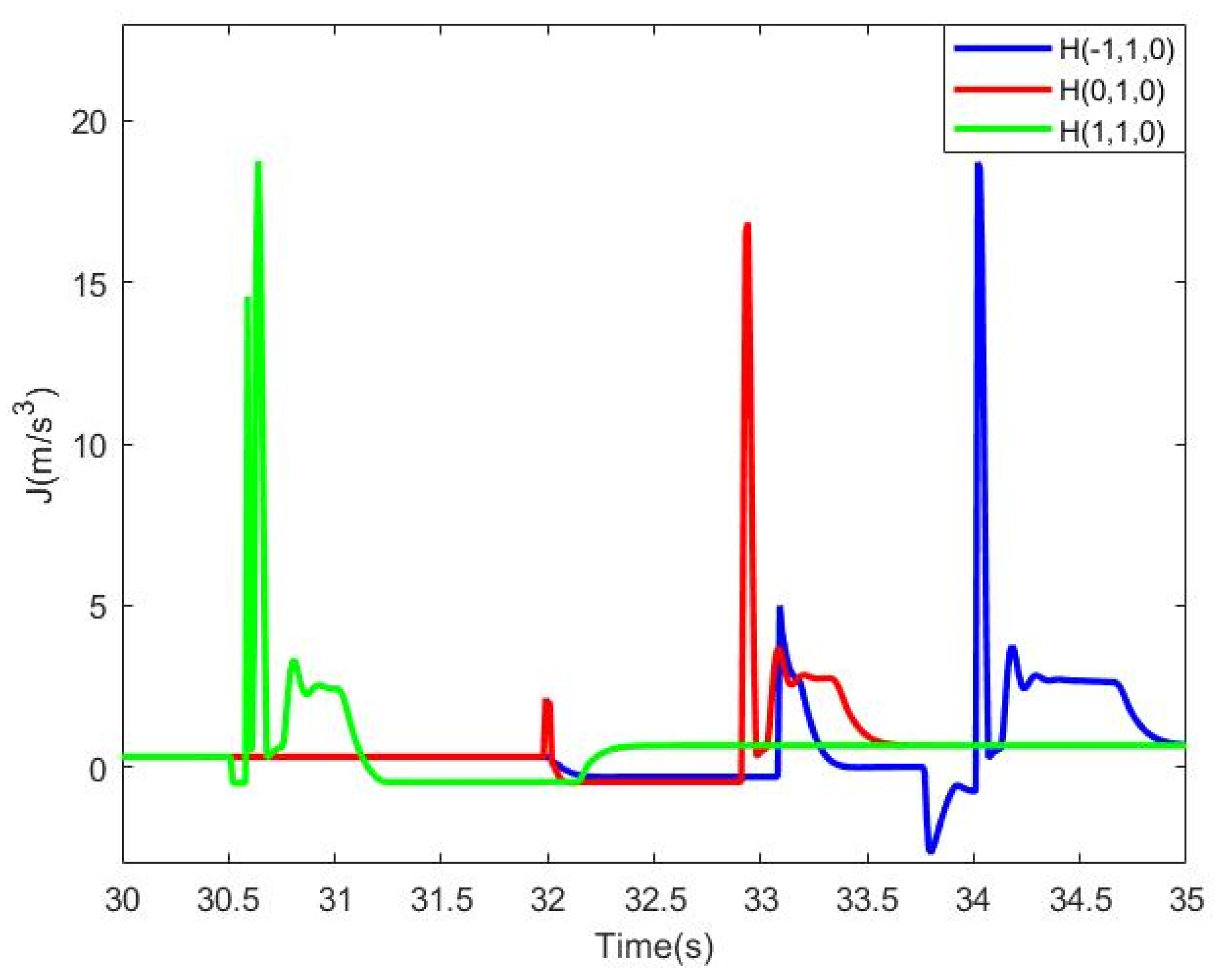
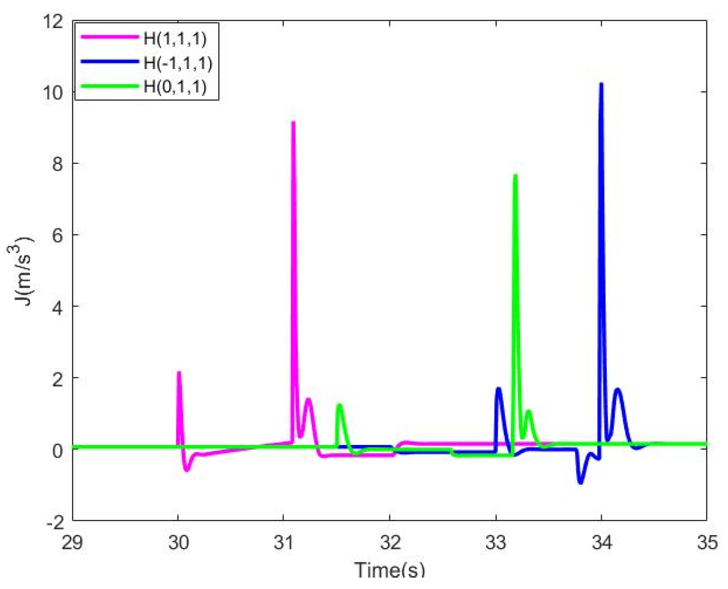
| Control Strategy | Max-Jerk (m/s3) | Control Strategy | Max-Jerk (m/s3) |
|---|---|---|---|
| H (0,1,1) | 7.81 | H (1,2,1) | 8.21 |
| H (0,1.5,1) | 8.14 | H (1,2.5,1) | 9.25 |
| H (0,2,1) | 6.27 | H (1,3,1) | 16.33 |
| H (0,2.5,1) | 8.12 | H (−1,1,1) | 10.55 |
| H (0,3,1) | 14.44 | H (−1,1.5,1) | 10.27 |
| H (1,1,1) | 9.36 | H (−1,2,1) | 9.64 |
| H (1,1.5,1) | 8.61 | H (−1,2.5,1) | 12.79 |
Publisher’s Note: MDPI stays neutral with regard to jurisdictional claims in published maps and institutional affiliations. |
© 2022 by the authors. Licensee MDPI, Basel, Switzerland. This article is an open access article distributed under the terms and conditions of the Creative Commons Attribution (CC BY) license (https://creativecommons.org/licenses/by/4.0/).
Share and Cite
Li, J.; Dong, H.; Han, B.; Zhang, Y.; Zhu, Z. Designing Comprehensive Shifting Control Strategy of Hydro-Mechanical Continuously Variable Transmission. Appl. Sci. 2022, 12, 5716. https://doi.org/10.3390/app12115716
Li J, Dong H, Han B, Zhang Y, Zhu Z. Designing Comprehensive Shifting Control Strategy of Hydro-Mechanical Continuously Variable Transmission. Applied Sciences. 2022; 12(11):5716. https://doi.org/10.3390/app12115716
Chicago/Turabian StyleLi, Jiang, Hao Dong, Bing Han, Yanan Zhang, and Zhongxiang Zhu. 2022. "Designing Comprehensive Shifting Control Strategy of Hydro-Mechanical Continuously Variable Transmission" Applied Sciences 12, no. 11: 5716. https://doi.org/10.3390/app12115716
APA StyleLi, J., Dong, H., Han, B., Zhang, Y., & Zhu, Z. (2022). Designing Comprehensive Shifting Control Strategy of Hydro-Mechanical Continuously Variable Transmission. Applied Sciences, 12(11), 5716. https://doi.org/10.3390/app12115716