Article

Selection Methodology of Composite Material for Retractable Main Landing Gear Strut of a Lightweight Aircraft

by
Muhammad Ayaz Ahmad
*,†,
Hamza Rafiq
,
Syed Irtiza Ali Shah
,
Sabih Ahmad Khan
,
Syed Tauqeer ul Islam Rizvi
and
Taimur Ali Shams
Department of Aerospace Engineering, College of Aeronautical Engineering, National University of Sciences and Technology, Islamabad 44000, Pakistan
*
Author to whom correspondence should be addressed.
These authors contributed equally to this work.
Appl. Sci. 2022, 12(11), 5689; https://doi.org/10.3390/app12115689
Submission received: 19 April 2022 / Revised: 25 May 2022 / Accepted: 25 May 2022 / Published: 3 June 2022
(This article belongs to the Section Aerospace Science and Engineering)

Abstract

:
The design and development of high-strength and low-weight composite landing gear struts is still a challenge in today’s world. In this study, a selection methodology for fiber-reinforced composite material for retractable main landing gear struts for specified lightweight aircraft up to 1600 kg mass is proposed. Four different fiber-reinforced composite materials, two each from the glass-fiber and carbon-fiber families, including E-glass fiber/epoxy, S-glass fiber/epoxy, T300 carbon fiber/epoxy, and AS carbon fiber/epoxy, were considered for analysis. For the design and analysis of a main landing gear strut, maximum landing loads for one point and two point landing conditions were calculated using FAA FAR 23 airworthiness requirements. Materials were categorized based on their strength-to-weight ratio and the Tsai-Wu failure criterion. Landing gear struts meeting the Tsai-Wu failure criterion, and having a maximum strength-to-weight ratio, were then modeled for performance under a collision detection test. This research concludes that T300 carbon fibre/epoxy is a recommended material for the manufacture of landing gear struts for specified lightweight aircraft.

1. Introduction

The landing gear system is considered to be one of the most significant systems of an aircraft. An aircraft experiences the highest structural loads at the time of landing and thus the design of the landing gear system is crucial. There are various configurations of landing gear systems depending on the design requirements of the aircraft. Designers in the aviation industry are always focused on saving weight in order to improve aircraft performance, pay-load capacity and fuel efficiency. Developments in the field of fiber-reinforced polymer composite materials have assisted designers in introducing lightweight aircraft components and systems owing to their high strength-to-weight ratio compared to conventional components and systems. Few lightweight aircraft are equipped with fiber-reinforced composite landing gear struts which are generally not retractable and are fixed with the fuselage. However, for long endurance flight requirements of any aircraft, retractable landing gear systems become a primary requirement.
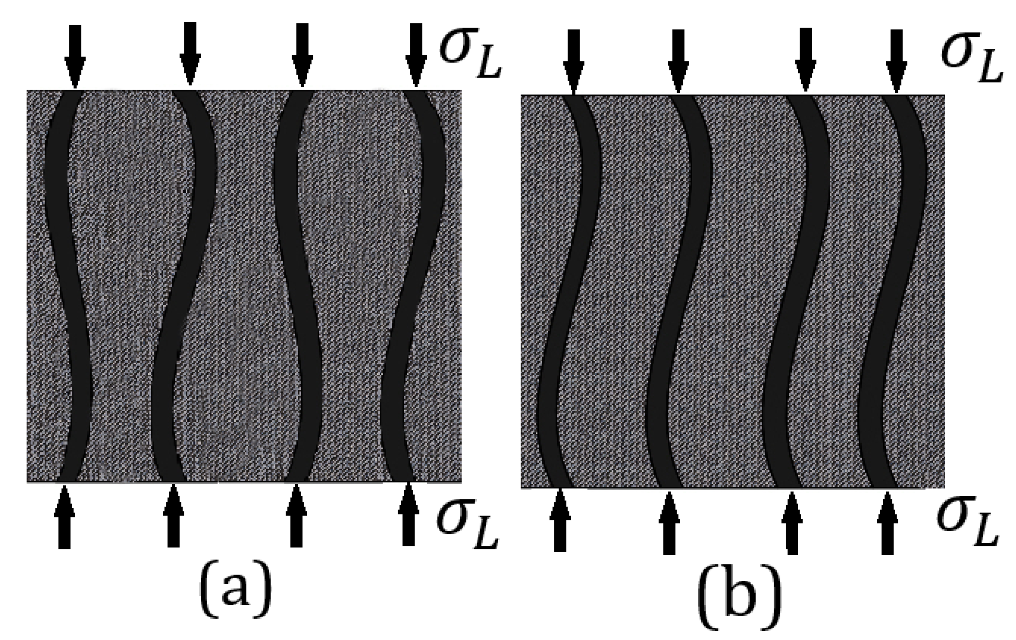
Composite materials are now widely used in almost all industries because of their low weight and high strength. Fiber-reinforced composite materials are one of the responses of the emerging applied sciences and technologies in the industry. Composite materials are designed and developed using two or more constituent materials having different chemical and physical properties. All the constituents of the composite material do not merge or dissolve into each other, rather the individual identity of each constituent material is retained. As a result, different phases are developed in the composite material, comprising continuous and discontinuous or discrete phases. The continuous phase is referred to as the ‘matrix’ and the discontinuous or discrete phase is called the ‘reinforcement’. The reinforcement can comprise long fibers, short fibers or particles. Fiber-reinforced composites in which all the fibers lie in the same direction are called unidirectional (UD) fiber-reinforced composites. A schematic representation of such unidirectional fiber-reinforced composites is shown in Figure 1. The continuous matrix may be constituted of polymer, ceramic, or metal material. The reinforcement or discontinuous phase is much stronger and stiffer than the continuous phase forming the matrix. The reinforcement is primarily responsible for strengthening the matrix. The key role of the matrix is to hold the reinforcement within the composite and to transfer and distribute the applied load across the discontinuous phase (reinforcement) [1].
The fibers may be long fibers or short fibers. Fibers are also used in the form of woven fabrics during the manufacture of composite materials. Further advanced types of fiber-reinforced composites are known as hybrid composites in which there are more than two constituent materials. In some advanced designs of composite materials, hollow or solid metal rods are used as reinforcements in addition to the fibers. The type of fiber, its volume ratio and orientation are important in the determination of the mechanical and physical properties of fiber-reinforced composite materials. The proportion of fiber volume in composite materials plays a basic and vital role in the determination of the strength and other mechanical properties of the composite materials.This is why the proportion of fiber volume is one of the key design parameters. In addition, the manufacturing processes also affects the mechanical behavior of composite materials. The orientation of fibers in a composite material is decided according to the desired mechanical properties for the application.
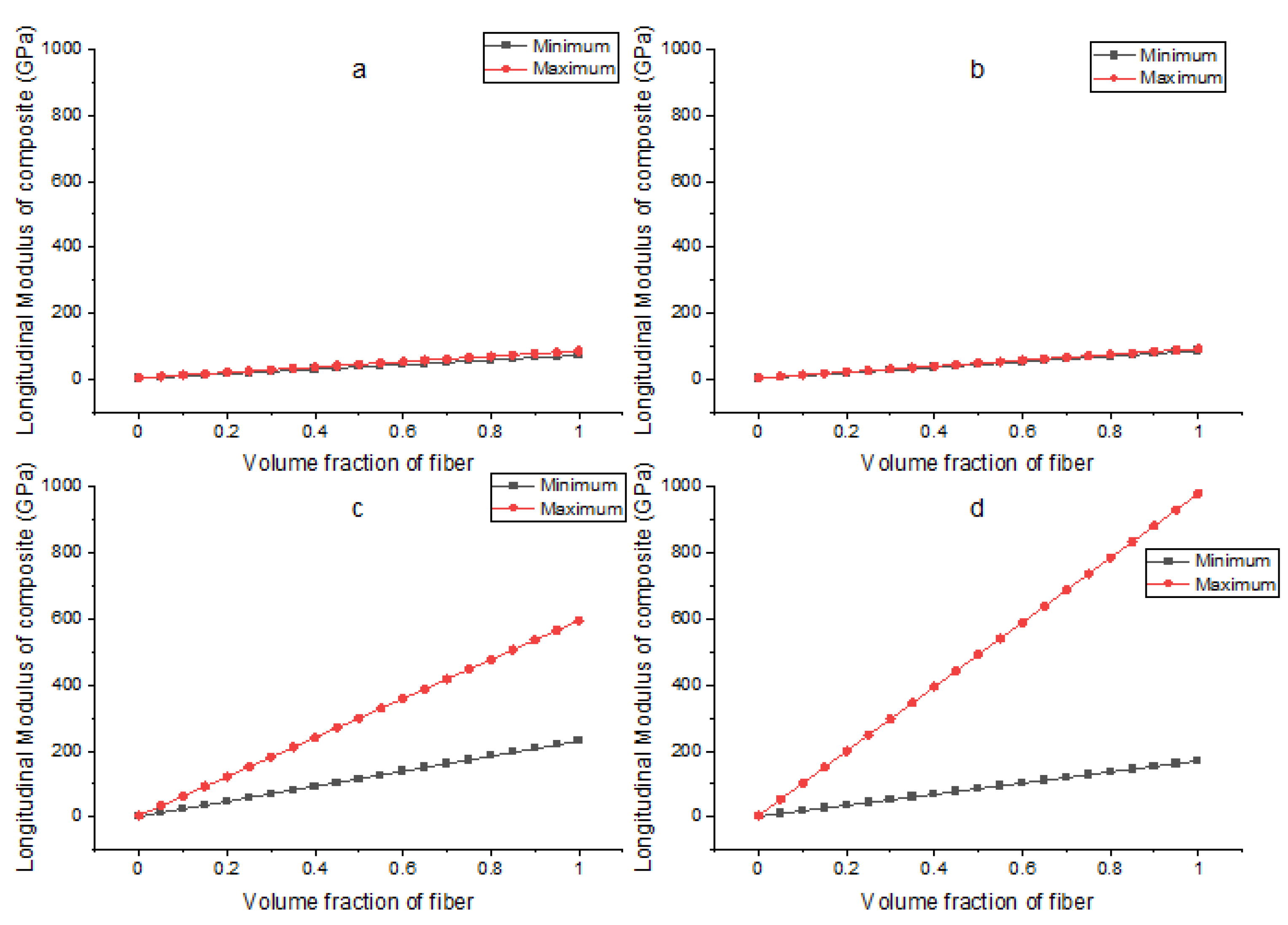
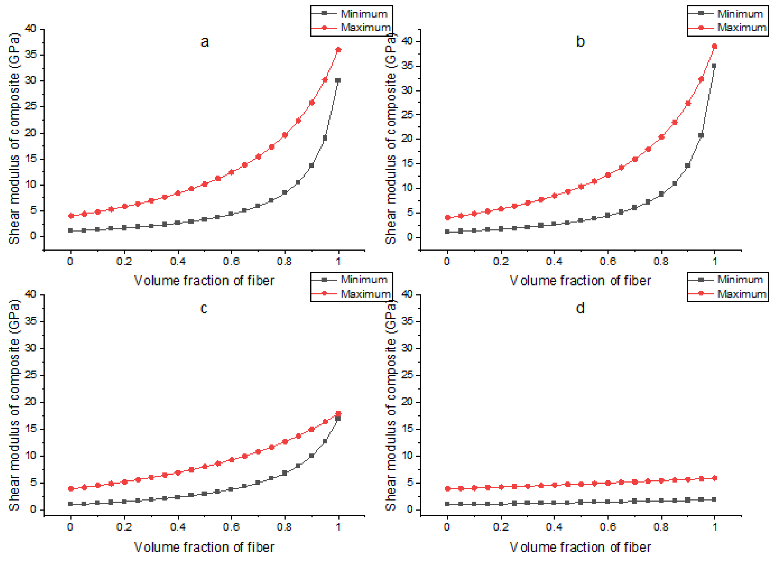
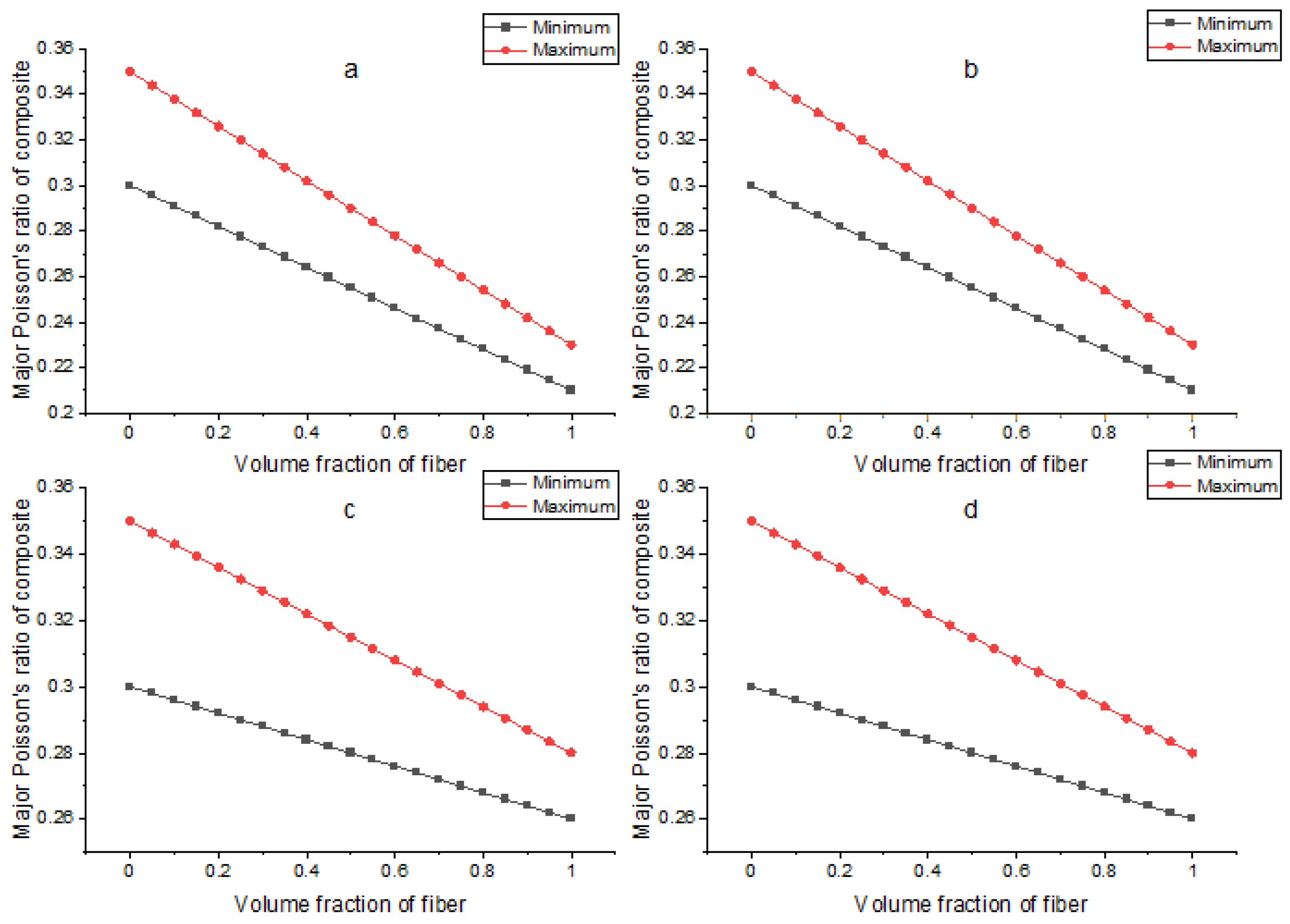
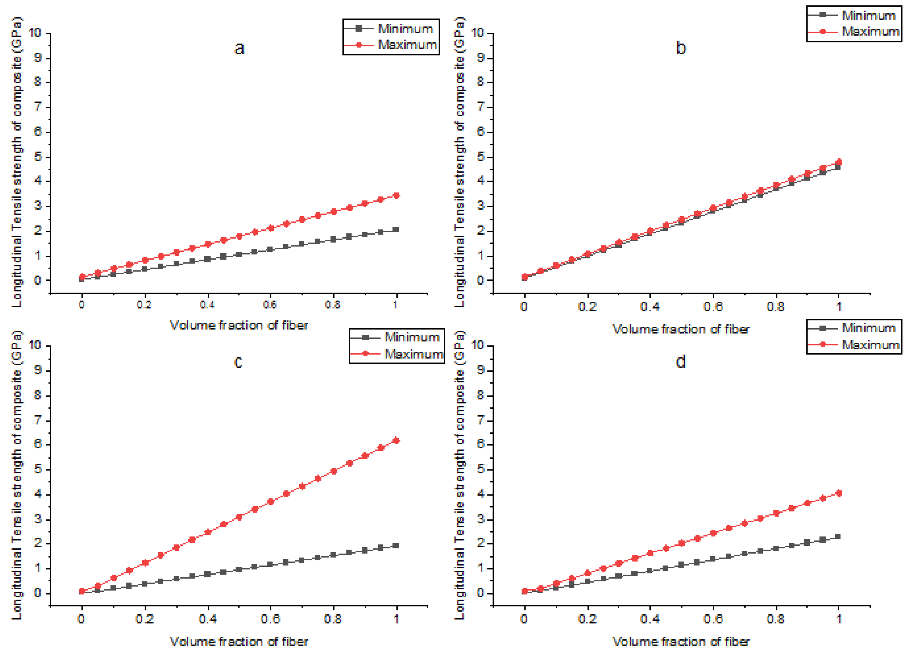
The mechanical properties of the composite materials depend on the distribution, chemical and physical interactions of its fibers and matrix. Experimentation is the simplest and most direct way to determine the mechanical properties of unidirectional fiber-reinforced composites. With the help of experimental measurements, the mechanical properties for a fixed ratio of fibers and matrix with a set of specimens fabricated in a single process can be determined. To determine the mechanical properties of fibrous composites with various fiber-matrix ratios, a wide range of specimens are fabricated in separate batches. For this reason, experimental measurements of the mechanical properties of fibrous materials with different fiber ratios become challenging in terms of time and cost which represent a major limitation. To address this issue, semi-empirical and theoretical methods have been developed to predict the mechanical properties of unidirectional fiber-reinforced composites [2].
Da and Yvonnet conducted a study to maximize the fracture toughness of particle-matrix composites [3]. In addition, evolutionary topology optimization and a phase method were combined and applied to the composites to evaluate their fracture toughness. The results of this study showed an increase in fracture toughness. Similar studies [4,5] have focused on the enhancement of failure strain and fracture toughness using topology optimization techniques on composite materials. Junker and Hackl [6] used methods derived from variational material modeling for topology optimization problems.
For an aircraft, the main landing gear takes most of the landing load upon landing which causes it to be a highly stressed area. The landing gear stores versatile energy that is easily convertible into another form upon landing. Therefore, the material used for the manufacture of landing gear struts must be capable of withstanding and absorbing this versatile energy. High mechanical stiffness, a high strength-to-weight ratio and high energy storage and damping capacity are key attributes that the main landing gear should possess [7].
The leaf spring is the oldest, but still one of the most frequently used, suspension systems in aerial vehicles. The amount of energy that is absorbed upon landing of an aircraft depends on the stiffness of the leaf spring. Therefore, key features, such as strength and stiffness, must be considered simultaneously during the design phase. Currently, both the automobile and aerospace industries are devoting effort to replacing metallic suspension systems with composite solid spring systems due to their enhanced structural strength and low weight. Patunkar et al. designed and analyzed glass-fiber-reinforced composite material and steel leaf spring suspension systems and compared their results [8]. Pro-E® was used for the design and modeling of the spring while ANSYS 10.0® was used for the analysis.The results of the analysis showed that the deflection of composite leaf spring was lower than that of steel leaf spring. However, an 84.4% weight reduction was achieved using the composite leaf spring.
Xue et al. published work related to simplified flexible multi-body dynamics for a main landing gear using flexible leaf spring [9]. Generally, the coupled rigid–flexible body model consumes extensive computational resources. In the same context, a new method based on modal analysis and the linear theory of elastodynamics was proposed to ensure the accuracy of results with reduced computational power. The same model was applied to landing gear systems during a computational drop test of an unmanned aerial vehicle (UAV) and the results were compared for the drop test. These results showed that error caused by linear approximation was in the acceptable range with fast and stable computational analysis.
Unmanned aerial vehicles (UAVs) are now widely used, with applications in military areas, structural inspections, weather monitoring and festival demonstrations, etc. For safe take-off and landing of a UAV, the landing gear is a critical element, for which high-strength and lightweight struts play a vital role. Composite struts are a promising solution for this purpose. A study performed by Liang et al. demonstrated the design, analysis and manufacturing of composite (CFRP) struts both computationally and experimentally [10].
In the aviation industry today, the design of lightweight landing gear struts for a given aerial vehicle is one of the most challenging and highly demanding tasks. In this context, Parmar et al. described the importance of landing gear struts and a selection methodology for given aircraft in connection with participation in the ‘Aero Design Series’ competition organized by the Society of Automotive Engineers (SAE) [11]. Among the available landing gear systems, a fiber-reinforced composite material landing gear system was selected considering the design constraints and landing load conditions.
Ayaz et al. published work related to the design and structural analysis of a fixed composite strut for a lightweight aircraft [12]. Different cross-sectional shapes, including rectangular, circular and elliptical, were modeled in ANSYS ACP® and analyzed. The least total deformation, along with least equivalent stresses and aerodynamic drag, were considered for the selection of a landing gear strut shape configuration. Based on the results of this research, an elliptical cross-sectional shape was recommended due to it having the least stress distribution and deformation values.
The application of fiber-reinforced composites in landing gear systems is very limited. Some of the landing gear assemblies, and associated components composed of fiber-reinforced composite materials, described in the literature are presented in Table 1.
As with other design processes, the design of aircraft landing gear is a multi-step process that begins with the design requirements and constraints. According to these design requirements, a preliminary design is produced which is then further developed into a detailed design. After the detailed design stage, a prototype is fabricated and tested [13]. The design landing loads based on which the preliminary design is developed are also considered as key design constraints. For a UAV and other lightweight aircraft, the design must be according to USAR certification standards [17,18]. The landing gear of an aircraft consists of multiple components. In the detailed design phase, the structure of all the landing gear components and their sizing is undertaken. In-depth design of the landing gear, including stress analysis, takes place during the detailed design phase. In the production planning phase, all the necessary steps and procedures for the fabrication are defined. The production planning phase finalizes the jigs, fixtures, fabrication procedures, tools, conditions and materials to produce the landing gear strut. After fabrication of the prototype, it undergoes various tests, including an actual drop test [19,20]. Ayaz et al. used the energy conservation principle to determine the height required for the drop test for any landing gear system [21].

1.1. Novelty of This Research

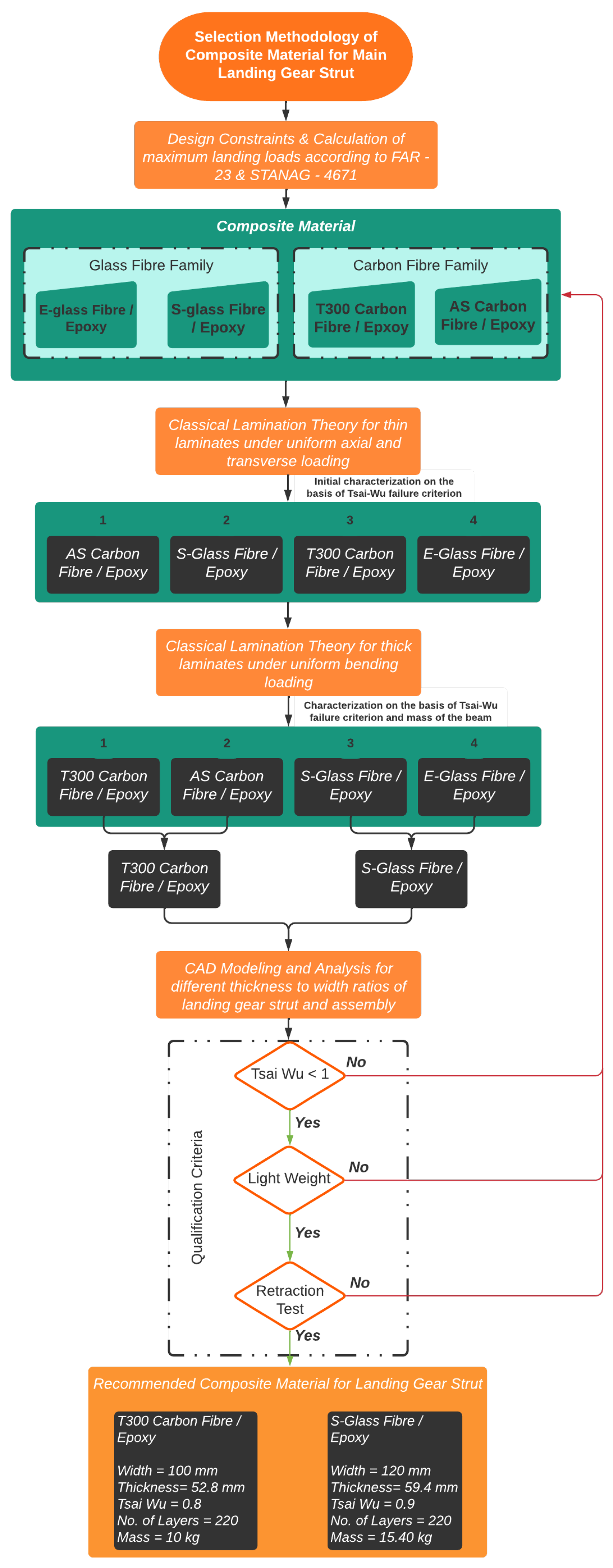
The selection methodology for composite material for the design and manufacture of landing gear struts is different than that for conventional material and was not identified in the literature. In this context, a comprehensive selection methodology for composite material has been developed and proposed which is considered to be the novel contribution of this research. Initially four different composite materials, two each from carbon- and glass-fiber families were considered and analyzed using classical lamination theory and beam theory for thin and thick laminates, respectively. The categorization of these materials was performed based on a high strength-to-weight ratio and qualification using the Tsai-Wu failure criterion. Once the composite pre-preg materials, one each from carbon- and glass-fiber families, were selected, a complete design and analysis of main landing gear struts was undertaken in relation to given landing loads and other design constraints. Based on a comprehensive analysis of landing gear struts according to the airworthiness standards FAA FAR-23 [18], a selection methodology for composite material for the manufacture of main landing gear struts is proposed and is shown in Figure 2. The material contributing towards qualification of the main landing gear strut with respect to the aforementioned criteria, with a maximum strength-to-weight ratio, was finally recommended for the manufacture of the main landing gear struts for a given aircraft.

1.2. Organization of the Paper

The paper is organized into eight sections. After the introduction section, Section 2 deals with the empirical model for calculation of the mechanical properties of composite materials. In Section 3 and Section 4, stress analysis of thin laminates under axial loading, and stress analysis of thick laminated composite beams under bending load, using an analytical approach, are discussed, respectively. Section 5 deals with the determination of landing loads. The design and analysis of different landing gear struts are discussed in Section 6. The conclusions from this research are explained in Section 7, followed by discussion of future work in Section 8.

2. Empirical Model for Calculation of Mechanical Properties

2.1. Modulus of Elasticity for UD Composites

The iso-strain approach states that the strain in the composite is equal to the strain in the matrix and fibers. Based on a simple model for unidirectional fiber-reinforced composite material, following the assumptions of the uniform diameter and the properties of fibers, with parallel orientation and continuous fiber, the following expression for the modulus of elasticity was derived [2]:
E c l = E f V f + E m V m
Similarly, the stress in the transverse direction of the composite is equal to the stress in the transverse direction of the matrix and fiber. Using this model, the transverse modulus of elasticity of unidirectional fiber-reinforced composite is expressed as follows [2]:
E c t = 1 V f E f + V m E m
Another expression to predict the transverse modulus of elasticity of a unidirectional fiber-reinforced composite was developed by Halpin and Tsai and is expressed as follows [22]:
E c t E m = 1 + ζ η V f 1 ζ η V f
η = E f E m 1 E f E m ζ
where, ζ is a constant for individual fiber cross-section. For fibers having a square or circular cross-section, Halpin and Tsai have taken ζ = 2 .
The expression for the shear modulus of elasticity of the unidirectional fiber-reinforced composite was also derived using the same constant stress and the iso-stress model that was used for the transverse modulus. The expression for the shear modulus is as follows:
G l t = G f G m G m V f + G f V m
Halpin and Tsai [22] also developed an expression for the shear modulus that is more accurate and is as follows:
G l t G m = 1 + ζ η V f 1 ζ η V f
For the shear modulus, Halpin and Tsai suggested that ζ = 2 .
η = G f G m 1 G f G m + ζ
The Poisson ratio is of two types, including the major and minor Poisson ratio. The major Poisson ratio expresses the relationship of the longitudinal stress to the transverse strain, whereas, the minor Poisson ratio expresses the relationship of the transverse stress to the longitudinal strain. In the case of unidirectional fiber-reinforced composites, the major Poisson ratio is only of significance where the minor Poisson ratio is very small and is neglected. The expression for the major Poisson ratio is also derived using the iso-stress model. The expression for the major Poisson ratio is as follows [2]:
ν l t = ν f V f + ν m V m

2.2. Fundamental Strength of UD Composites

The longitudinal tensile strength of unidirectional fiber-reinforced composite materials depends on the volume ratio and ultimate tensile strain of the fiber and the matrix. The longitudinal tensile strength is expressed in two cases. In the first case, the failure occurs when the matrix reaches its ultimate strain. In the second case, failure of the composite occurs when the fiber reaches its ultimate strain. The factor V m i n plays an important role in handling both the cases independently. If V f < V m i n , then the expression (9) will be used. However, if V f V m i n , then the expression of the second case, as expressed in Equation (10), is applied [22,23]. Here, V m i n and V f are the minimum fiber volume fraction that ensures fiber-controlled composite failure, and the volume fraction of fiber, respectively.
σ c l u , t = σ m u ( 1 V f )
σ c l u , t = σ f u V f + ( σ m ) ε f * ( 1 V f )
V m i n = σ m u σ m ε f * σ f u + σ m u ε f *
The response of unidirectional fiber-reinforced composite to longitudinal compressive stress is quite different from the response to longitudinal tensile stress. This is because, under longitudinal compressive stress, the unidirectional fiber-reinforced composites exhibit various modes of failure. In the case of elastic behavior of the matrix, two different failure modes can occur. These are the extensional mode and the shear mode of micro-buckling of fibers. The extensional mode of failure occurs when the volume ratio of fibers is less than 0.2. For unidirectional fiber-reinforced composites having a higher fiber volume ratio, the shear mode of micro-buckling of fibers takes place, as depicted in Figure 3 [22,23].
The expression of longitudinal compressive strength ( σ c l u , c ) for the extensional model is derived using the energy method [24]. The expression is as follows:
σ c l u , c = 2 V f V f E m E f 3 ( 1 V f )
The expression of longitudinal compressive strength ( σ c l u , c ) for the shear mode is as follows [25]:
σ c l u , c = G m 1 V f
The longitudinal compressive modulus of unidirectional fiber-reinforced composite is almost equal to the longitudinal tensile modulus of unidirectional fiber-reinforced composite and can be used as an alternate to each other [26].
The transverse tensile strength of the unidirectional reinforced composites is less than the transverse strength of the matrix. The unidirectional fibers in a composite result in stress concentration upon transverse loading. The stress concentration factor (SCF) is calculated to find the transverse tensile strength of the unidirectional fiber-reinforced composite. The transverse tensile strength of the unidirectional reinforced composites is controlled by the ultimate strength of the matrix and the stress concentration factor. The expression to predict the transverse tensile strength ( σ c t u , t ) is as follows [2]:
σ c t u , t = σ m u SCF
SCF = 1 V f [ 1 E m E f ] 1 4 V f π 1 2 [ 1 E m E f ]
The micro-mechanical behavior of a unidirectional fiber-reinforced composite under transverse compressive loading is difficult to predict because, under transverse compressive loading, the iso-stress and the iso-strain approaches become invalid. An empirical formula to predict the transverse compressive strength ( σ c t u , c ) of unidirectional fiber-reinforced composite is written as follows [27]:
σ c t u , c = σ m u , c C ν [ 1 + ( V f V f ) ( 1 E m E f ) ]
The expression for the reduction factor is as follows:
C ν = 1 4 V ν π ( 1 V f )
A unidirectional fiber-reinforced composite can fail under in-plane shear stress due to failure of the matrix, extensive crack propagation, debonding of fibers, and matrix or shear stress concentration. An empirical formula for the shear strength ( σ c u , s h e a r ) of unidirectional fiber-reinforced composite is written as follows [27]:
τ c u , s = τ m u , s C ν [ 1 + ( V f V f ) ( 1 E m E f ) ]

2.3. Determination of Mechanical Properties

The mechanical properties of unidirectional fiber-reinforced composites were calculated analytically using MATLAB®. To verify these results, the theoretical mechanical properties were compared with the actual mechanical properties of some commercially available laminae shown in Table 2. Complete plots depicting variation of the mechanical properties of composite material with varying fiber ratios are also shown in Appendix A. From these plots, it can be seen that the strength and mechanical properties of fiber-reinforced composite materials increase with increase in fiber volume ratio up to 99 percent. However, the properties stop following the models of mathematical expressions after some value of fiber volume ratio, due to the unavailability of a sufficient amount of matrix to adhere the composite constituents to each other [28].

2.4. Failure Criteria

Many failure theories have been developed for the failure analysis of composite materials. Among these theories, the Tsai-Wu failure theory is considered to be the most advanced failure theory and is therefore used in the design and analysis phases of this research. According to the Tsai Wu failure theory, the lamina will not fail if it satisfies the following inequality [29]:
H 1 σ l + H 2 σ t + H 6 τ l t + H 11 σ l 2 + H 22 σ t 2 + H 66 τ l t 2 + 2 H 12 σ l σ t < 1
where
H 1 = 1 σ c l u , t 1 σ c l u , c
H 2 = 1 σ c t u , t 1 σ c t u , c
H 6 = 0
H 11 = 1 σ c l u , t σ c l u , c
H 22 = 1 σ c t u , t σ c t u , c
H 66 = 1 ( τ m u , s h e a r ) 2
H 12 = 1 2 1 σ c t u , t σ c t u , c σ c l u , t σ c l u , c

3. Stress Analysis of Thin Laminates under Axial Loading

Initially, analysis of thin laminates of all the four composite materials was undertaken using MATLAB®. The materials were stacked up in 0 deg ply orientation and thin laminated unidirectional lamina plates of 1 m2 under axial loading were considered during this analysis. The applied loads were kept the same for all the four plates where the longitudinal load was 200 kN and the transverse load was 100 kN. According to the Tsai-Wu failure criterion theory, structures having a Tsai-Wu failure factor value less than one are considered safe. Based on these initial results, as shown in Table 3, AS carbon fiber/epoxy had the minimum value of the Tsai-Wu failure factor, and hence was considered the best material according to classical lamination theory which is only valid for thin laminates. However, for the landing gear strut, analysis of thick laminated composite beams was required to be performed.

4. Stress Analysis of Thick Laminated Composite Beams under Bending Load

After performing the analysis on thin laminates, thick laminated composite beams were modeled and Tsai-Wu failure factors were evaluated accordingly using an analytical approach. The purpose of this study was to evaluate the strength-to-weight ratio of all these materials for their subsequent selection and utilization for design and analysis of the main landing gear strut.
The results of the theoretical stress analysis of laminated composite beams under bending load are depicted in Table 4. The applied bending load was kept constant at 35,000 N in all cases. Passing the criterion of a Tsai-Wu failure factor less than or equal to 0.5 was set in order to evaluate the total requirement of material in terms of weight which could sustain the applied load. The aim of this analysis was to select two composite materials, one each from carbon- and glass-fiber families, meeting the stringent requirement of a Tsai-Wu value less than 0.50 with minimum weight.
From the results shown in Table 4, it was concluded that T300 carbon fiber/epoxy lamina was the safest material on the basis of the strength-to-weight ratio among all the four beams along with an acceptable deflection value under bending load. Hence, T300 carbon fiber/epoxy composite material was recommended for further analysis from the carbon family. Similarly, it was further observed that the E-glass laminated beam had a maximum weight of 8.26 kg and was considered as the heaviest among all the beams. Therefore, the E-glass/epoxy pre-preg material was rejected and S-glass/epoxy composite material from the glass fiber family was recommended for further analysis.
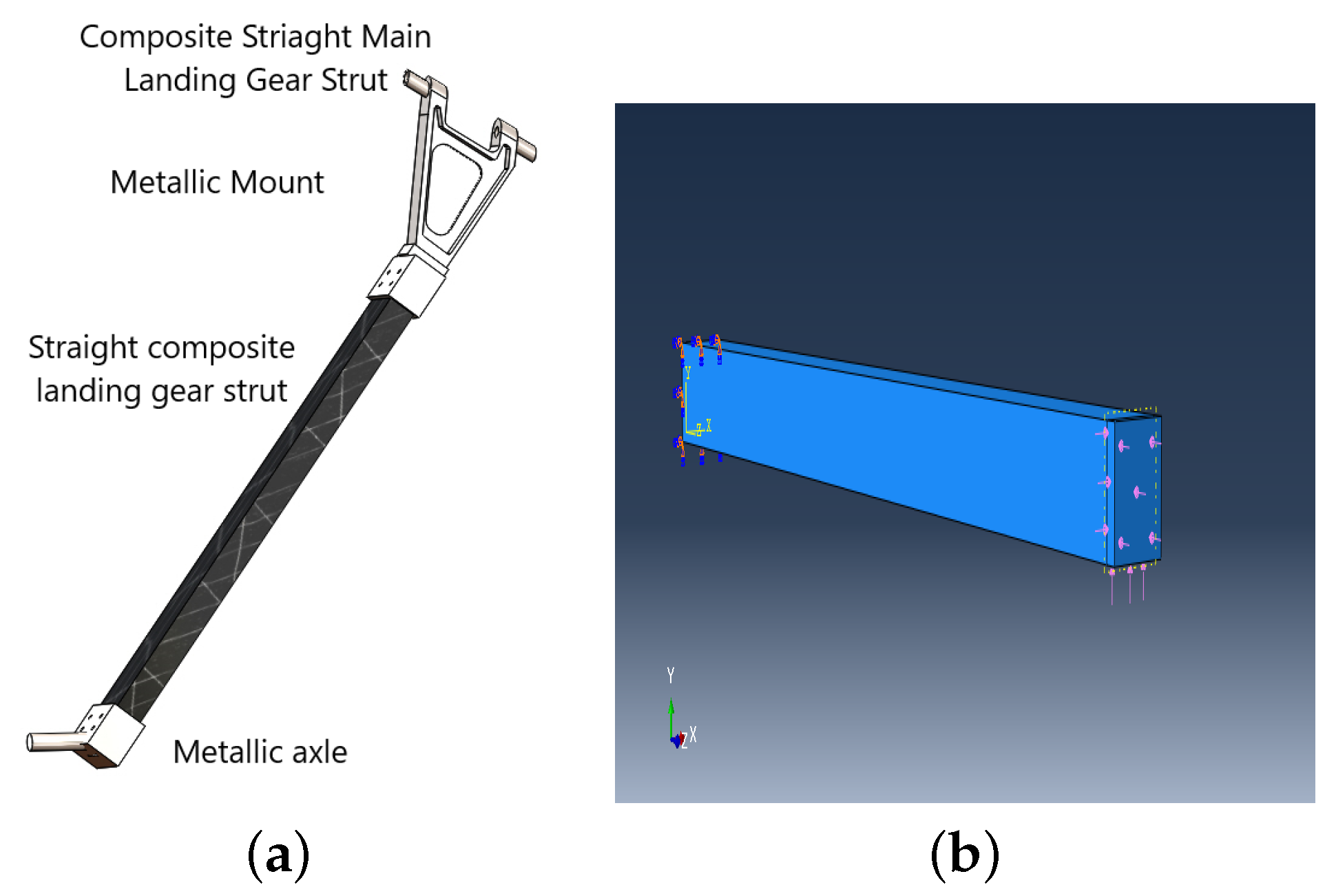
In the next step, composite beams of recommended material T300 carbon fiber/epoxy and S-glass fiber/epoxy were modeled and analyzed using Abaqus CAE®. The results of the computational analysis were then compared with the analytical analysis; the comparison is shown in Table 5. The comparison of the theoretical and computational results showed that the results for the deflection of the beams were the same in both the approaches. However, the values of the Tsai-Wu failure factor were found to be different. This was because the shear stress results of classical lamination theory in thick laminates are not realistic due to certain assumptions in the theory [30,31]. The boundary condition is depicted in Figure 4. It can be seen that the laminated beam acts as a cantilever beam where one end of the beam is fixed using the encastre boundary condition in ABAQUS CAE® while the other end is subjected to 35,000 N force. The results of computational analysis are shown in Figure 5a–d.

5. Determination of Landing Loads

The landing loads acting on the landing gears are different in different landing conditions. These landing load conditions and the landing load associated with each condition are depicted in Table 6 as per UAV Systems airworthiness requirements (USAR) [17] and FAA FAR 23 [18]. As the main focus of this research was to select a composite material for manufacturing of main landing gear struts, the maximum landing load condition that is one point landing was applied during further analysis.

6. Design and Analysis of Main Landing Gear Strut

6.1. Design and Analysis of a Straight Main Landing Gear Strut

In the design phase of the main landing strut, initially straight leg, inspired from MQ-9 Reaper for both the materials (S-glass fiber/epoxy and T300 carbon fiber/epoxy), was modeled. A total of six design models (three each for carbon- and glass-fiber materials) having a fixed number of plies and thickness-to-width ratios were developed and their stress analysis under the one point landing load condition was performed using Abaqus CAE®. The results of these analyses showing thickness and mass of the strut, Tsai-Wu failure criterion factor and deflection of the strut are shown in Table 7. It is worth highlighting that square beams composed of both the materials successfully met the Tsai-Wu criterion under the given loading conditions and were considered the safest compared to the others. The boundary conditions and computational results for the qualified struts are shown in Figure 6a,b and Figure 7a–d, respectively. However, when these qualified straight struts were subjected to a collision detection test for retraction on given aircraft, some could not clear the retraction test due to their collision with the bulkhead/fuselage, and, hence, design of a straight strut was not considered a viable option.

6.2. Design and Analysis of Retractable (Curved) Main Landing Gear Strut

After the failure of the retraction test of the straight main landing gear strut, a retractable (curved) landing gear strut model was developed in CATIA V5®. The CAD model of the retractable main landing gear strut, along with other sub-assemblies, is shown in Figure 8. This model helped in stress analysis of the strut within the allowable limits of thickness and width under the applied loading conditions.
In the first phase of this analysis, only composite landing gear struts without mounting brackets were analyzed computationally. Landing gear struts having different thickness-to-width ratios were analyzed in order to obtain the most suitable design in terms of the Tsai-Wu failure criterion, mass and deflection of the strut. Based on the results obtained from the straight landing gear strut, the same dimensions in terms of thickness-to-width ratio were used for the retractable landing gear strut design as a first option. However, using the same dimensions could not meet the Tsai-Wu failure criterion, and, hence, struts having different dimensions were analyzed. The dimensions of the strut in terms of thickness and width were varied within the allowable limits to ensure smooth retraction of the landing gear strut. The results of these analysis are tabulated in Table 8. The Tsai-Wu failure criterion expresses the effect of all the stresses in each mesh element. Figure 9 depicts the variation in the Tsai-Wu criteria factor and the mass of different models of landing gear struts. From these results, the T300 fiber/epoxy composite material strut having dimensions of 52.8 mm × 75 mm just meeting the Tsai-Wu failure criterion with a value of 0.98 with a minimum mass of 7.56 kg was recommended for further analysis to evaluate the effects of joining mounting brackets of the landing gear assembly.

Analysis of Retractable Main Landing Gear Strut Assembled with Mounting Bracket

In the second phase of the analysis, the stress analysis of retractable composite main landing gear strut assembled with mounting bracket was carried out. To validate the trend of this analysis, recommended dimensions of the model (52.8 mm × 75 mm) were used. When the analysis was performed for the strut and mounting bracket joined together with the help of Qty 4 bolts, the assembly could not meet the Tsai-Wu failure criterion as its value was found to be 4.6. In order to reduce the value of the Tsai-Wu failure factor for qualification of the assembly, different mechanical options of joining composite strut and metal mount including bolts, nuts, bolt loads and washers were also used. The value of the Tsai-Wu failure factor reduced significantly for a combination of bolts, nuts, bolt load and washers; however, the assembly could not meet the Tsai-Wu failure criterion for given dimensions of landing gear strut under the one point landing load condition. The results of the same analysis are shown in Table 9. It is pertinent to note from the results mentioned in Table 8, that a strut having the same dimensions qualified when analyzed without a mount under the one point landing load condition. The reason for the failure of the assembly with a mounting bracket was the stress concentration around the bolt holes of the composite strut.
To overcome the failure of the landing gear assembly with respect to the Tsai-Wu failure criterion, the option of hybrid joints was also analyzed. The hybrid joints (bolted + bonded) have 100% and 5% more load carrying capacity compared to the bolted and bonded joint, respectively [32]. In this analysis phase, the mounting was joined to the strut by bolts and the contact surfaces were assumed to be perfectly bonded. Additionally, based on the trend observed from Table 8, the thickness-to-width ratio of the designed strut was further reduced within the allowable limits of dimensions for the retraction test to obtain the safest Tsai-Wu failure criterion factor. After certain iterations, the design models of T300 carbon fiber/epoxy, having dimensions of (52.8 mm × 100 mm), and S-glass fiber/epoxy, having dimensions of (59.4 mm × 120 mm), were considered for analysis of the complete landing gear assembly with a mounting bracket under the one point landing load condition. Satisfactory results of this analysis showing the Tsai-Wu failure criterion, mass and deflection of the strut are shown in Table 10. The same analysis was also performed for the two point landing load condition and the results of the this are shown in Table 11. The computational results for the landing gear strut for both the landing conditions are also shown in Figure 10a–d and Figure 11a–d. The stress analysis of the mounting bracket under the one point landing load condition is also shown in Figure 12. These results indicate that the designed structures were safe for operation against the required maximum loads encountered at the time of one point and two point landing scenarios. As the strength-to-weight ratio is considered to be the most important parameter in this research, the T300 carbon fiber/epoxy is recommended as the most suitable material for the manufacture of composite main landing gear struts for the given lightweight aircraft.
After qualification of the designed model composed of T300 carbon fiber/epoxy on the basis of its minimum mass and maximum strength, a collision detection test was also performed to ensure smooth retraction of the landing gear assembly into the fuselage. The assembly successfully qualified the retraction test criteria and the results are shown in Figure 13a–c.
During this analysis, the effects of co-efficient of friction on Tsai-Wu failure factor were also studied. It has been found that when the parts are assembled, the co-efficient of friction among these parts plays a significant role in reducing the Tsai-Wu failure criterion value which in turn ensures the safety of the assembled structure. To validate this trend, an analysis was performed for the co-efficient of friction ranging from 0.1–0.9 among all the contact surfaces. Figure 14 shows that a higher value of the co-efficient of friction reduces the value of the Tsai-Wu failure criterion factor. From the literature, it was found that the co-efficient of friction value between two steel surfaces is 0.7 and the coefficient of friction value between steel and fiber-reinforced plastic laminate is 0.4 [33].

6.3. Grid Independence for the Analysis

The results of computational analysis are greatly affected by the mesh size of the model. To obtain accurate results from the computational analysis, it is essential to perform the analysis for any required parameter using different mesh sizes in order to ensure consistent results for different mesh sizes. Generally, the stresses in a structure do not become independent of the mesh size; rather, they keep on increasing or decreasing with mesh size due to the stress singularities at stress concentration locations [34]. So, the mesh independence in this analysis was carried out using the deflection parameter. The plot in Figure 15 represents the number of elements of assembly at which the results become independent of the number of elements or the mesh element size.

7. Conclusions

The purpose of this research was to propose a selection methodology for composite material for the manufacturing of a retractable main landing gear strut for a given lightweight aircraft. For this purpose, four uni-directional fiber-reinforced composite materials, two each from carbon- and glass-fiber families, were considered. Initially classical lamination theory was used on thin laminated composite plates to categorize these four different materials based on the strength-to-weight ratio. Initial categorization of these materials was as follows:
AS carbon fiber/epoxy > S-glass fiber/epoxy > T300 carbon fiber/epoxy > E-glass fiber/epoxy
In the next phase of analysis, thick laminated composite beams were subjected to the same bending load under the stringent requirement of the Tsai-Wu failure criterion. The categorization of these materials based on the strength-to-weight ratio was as follows:
T300 carbon fiber/epoxy > AS carbon fiber/epoxy > S-glass fiber/epoxy > E-glass fiber/epoxy
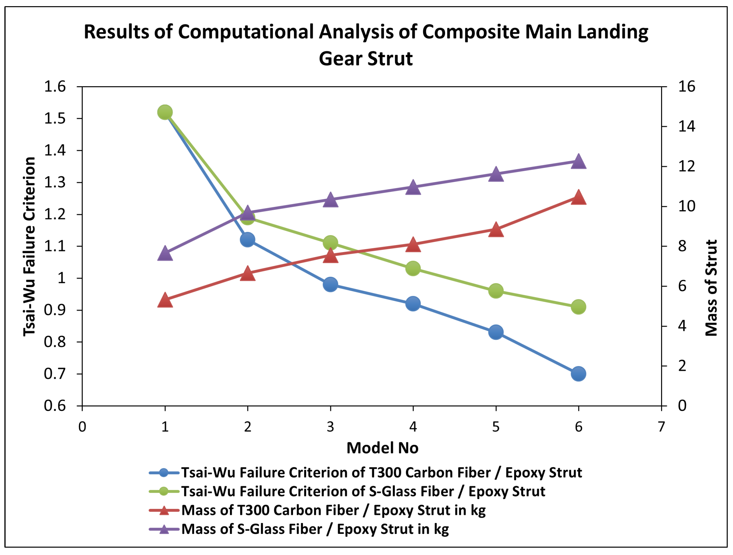
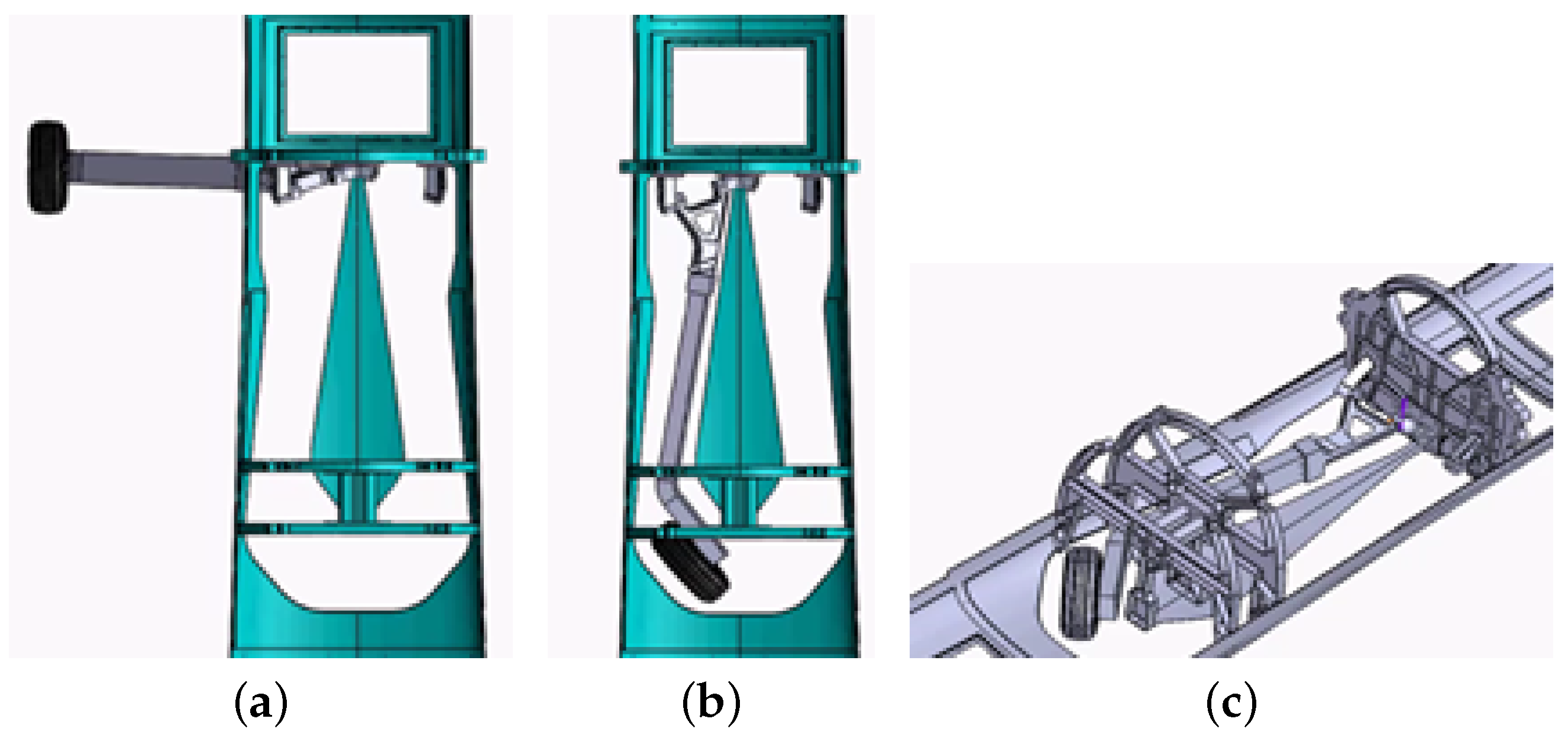
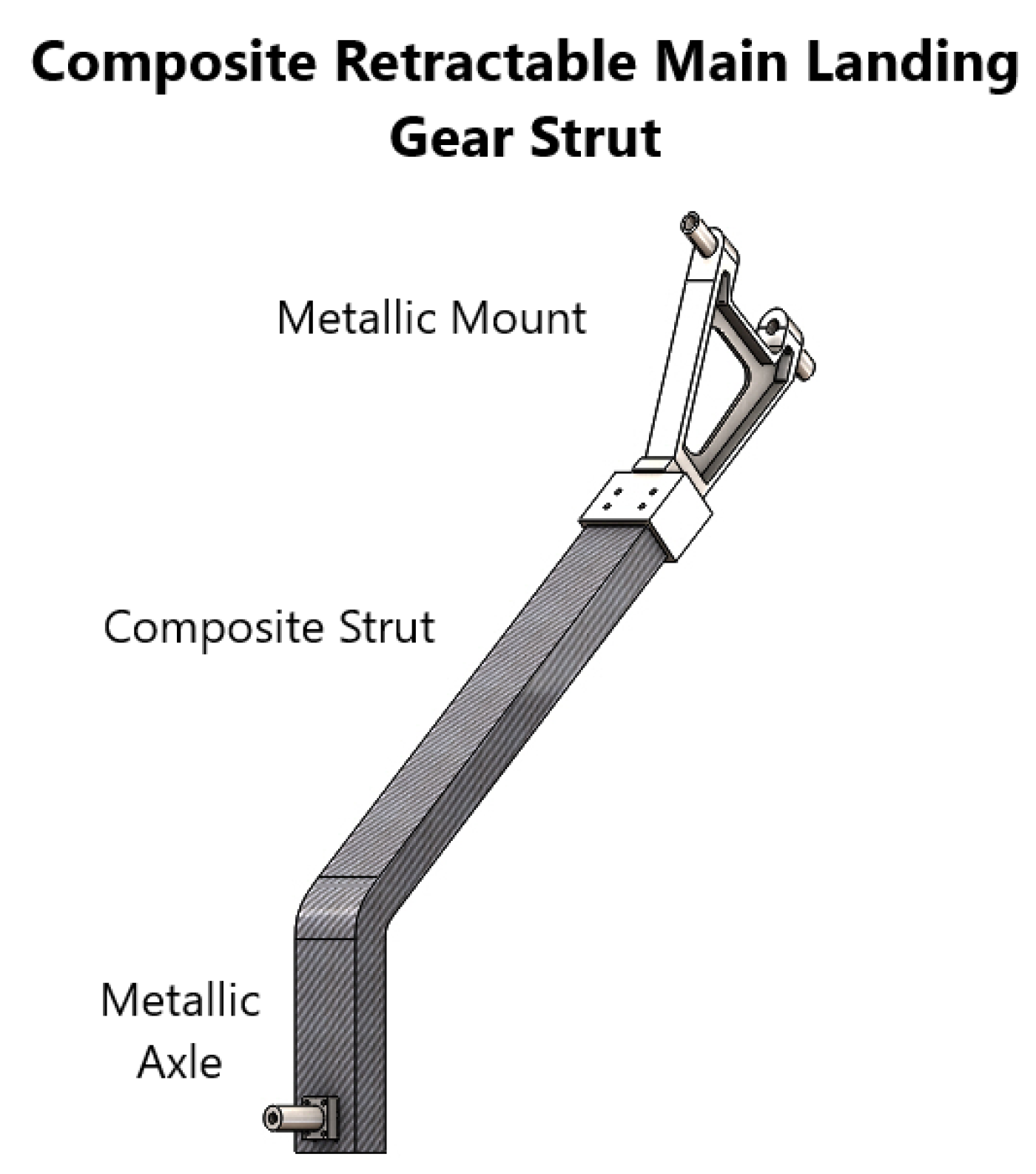
For the design and analysis of the main landing gear strut of the given aircraft, the maximum landing loads for one point and two point landing conditions were calculated using FAA FAR 23 airworthiness requirements. After that, the main landing gear strut was modeled using recommended materials from carbon and glass fiber families and analyzed computationally against the calculated landing loads using Abaqus/CAE®. In the first phase of analysis, only the landing gear strut without mounting bracket and axle was analyzed, and the T300 carbon fiber/epoxy strut just meeting the Tsai-Wu failure criterion (0.98) and having a minimum mass of 7.56 kg was recommended for further analysis with a mounting bracket and axle. In the second phase of analysis, the same landing gear strut could not meet the Tsai-Wu failure criterion due to stress concentration around the bolt holes of the strut when the mounting bracket and axle were assembled. For qualification of the composite strut with mounting bracket and axle, different options of joints were considered, along with change in dimensions (width) of the recommended struts within the given design constraints. Finally, the option of a hybrid joint (bolted and bonded) was applied to the landing gear strut design with the safest Tsai-Wu failure criterion value having dimensions of (52.8 mm × 100 mm) and (59.4 mm × 120 mm) for T300 carbon fiber/epoxy and S-glass fiber/epoxy, respectively, and the desired results were obtained. CATIA V5® was used to perform a collision detection test of these qualified struts to ensure smooth retraction on the aircraft. It was concluded that the main landing gear strut of T300 carbon fiber/epoxy, having a mass of 10 kg for the one point landing condition and 7.4 kg mass for the two point landing condition, was 1.5 times lighter than S-glass fiber/epoxy and was recommended for the manufacture of the main landing gear strut of a aircraft having an all up mass of 1600 kg.

8. Future Work

Based on the recommendations of this research, manufacture of composite main landing gear struts for a given aircraft having an all up mass of 1600 kg using T300 carbon fiber/epoxy will be undertaken after necessary experimental verification.

Author Contributions

Conceptualization, methodology and final write-up: M.A.A.; funds acquisition and supervisor of research work: S.I.A.S.; project administration: H.R.; software, results validation: S.A.K.; proof-reading: S.T.u.I.R.; and resources: T.A.S. All authors have read and agreed to the published version of the manuscript.

Funding

The This research work was funded by Higher Education Commission (HEC) of Pakistan vide HEC grant number TDF 03-332 and National University of Sciences and Technology, Islamabad, Pakistan.

Institutional Review Board Statement

Not applicable.

Informed Consent Statement

Not applicable.

Data Availability Statement

Not applicable.

Conflicts of Interest

The authors declare no potential conflict of interest with respect to the research, authorship, and/or publication of this article.

Appendix A

Figure A1. Depicts the variation in longitudinal modulus of (a) E-glass, (b) S-glass, (c) T300 carbon fiber and (d) AS carbon with volume of fiber. It can be seen that as the fiber ratio increases, the longitudinal modulus of all the materials increases. It is also noted that there is a linear increase in the modulus. For the carbon-fiber family, the increase in the modulus is far more compared to the glass-fiber family.
Applsci 12 05689 g0a1
Figure A2. Depicts the variation in transverse modulus of (a) E-glass, (b) S-glass, (c) T300 carbon fiber and (d) AS carbon with volume of fiber. It can be seen that as the fiber ratio increases, the transverse modulus of the all the materials increases. It is also noted that at a fiber ratio of 1, the value of the transverse modulus is maximum; however, this cannot be achieved as there would be no matrix for bonding.
Applsci 12 05689 g0a2
Figure A3. Depicts the variation in shear modulus of (a) E-glass, (b) S-glass, (c) T300 carbon fiber and (d) AS carbon with volume of fiber. It can be seen that as the fiber ratio increases, the shear modulus of the all the materials increases. The graph follows a similar trend for (ac); however, for (d) the material varies linearly with less variation with the fiber ratio.
Applsci 12 05689 g0a3
Figure A4. Depicts the variation in the major Poisson ratio of (a) E-glass, (b) S-glass, (c) T300 carbon fiber and (d) AS carbon with volume of fiber. It can be seen that the value of the Poisson ratio is maximum at low fiber ratios and starts to decrease as the fiber ratio increases. The trend is similar for all the materials.
Applsci 12 05689 g0a4
Figure A5. Depicts the variation in longitudinal tensile strength of (a) E-glass, (b) S-glass, (c) T300 carbon fiber and (d) AS carbon with volume of fiber. It can be seen that as the fiber ratio increases, the longitudinal tensile strength of the all the material increases. It is also noted that there is a linear increase in the modulus. For the carbon-fiber family, the increase in the modulus is far more compared to the glass-fiber family.
Applsci 12 05689 g0a5
Figure A6. Depicts the variation in longitudinal compressive strength of (a) E-glass, (b) S-glass, (c) T300 carbon fiber and (d) AS carbon with volume of fiber. It can be seen that the value of longitudinal compressive strength is maximum at 20% fiber ratio and then decreases upto 100% fiber ratio.
Applsci 12 05689 g0a6
Figure A7. Depicts the variation in transverse tensile strength of (a) E-glass, (b) S-glass, (c) T300 carbon fiber and (d) AS carbon with volume of fiber. It can be seen that the value of transverse tensile strength is maximum at 0% fiber ratio but the strength starts to decline and reaches the minimum at 100% fiber ratio.
Applsci 12 05689 g0a7
Figure A8. Depicts the variation in transverse compressive strength of (a) E-glass, (b) S-glass, (c) T300 carbon fiber and (d) AS carbon with volume of fiber. It can be seen that a wide range between minimum and maximum transverse compressive strength is obtained with increasing fibre ratio.
Applsci 12 05689 g0a8
Figure A9. Depicts the variation in shear strength of (a) E-glass, (b) S-glass, (c) T300 carbon fiber and (d) AS carbon with volume of fiber. It can be seen that a wide range between minimum and maximum shear strength is obtained with increasing fibre ratio.
Applsci 12 05689 g0a9

References

  1. Chung, D.D. Composite Materials: Science and Applications; Springer Science & Business Media: Berlin, Germany, 2010. [Google Scholar]
  2. Agarwal, B.; Broutman, L. Analysis and Performance of Fiber Composites, 2nd ed.; John Wiley & Sons: Hoboken, NJ, USA, 1990. [Google Scholar]
  3. Da, D.; Yvonnet, J. Topology optimization for maximizing the fracture resistance of periodic quasi-brittle composites structures. Materials 2020, 13, 3279. [Google Scholar] [CrossRef] [PubMed]
  4. Da, D. Topology Optimization Design of Heterogeneous Materials and Structures; John Wiley & Sons: Hoboken, NJ, USA, 2019. [Google Scholar]
  5. Da, D.; Qian, X. Fracture resistance design through biomimicry and topology optimization. Extrem. Mech. Lett. 2020, 40, 100890. [Google Scholar] [CrossRef]
  6. Junker, P.; Hackl, K. A variational growth approach to topology optimization. Struct. Multidiscip. Optim. 2015, 52, 293–304. [Google Scholar] [CrossRef]
  7. Ciobanu, I.; Drăgus, L.; Tigleanu, L.; Frunza, C.; Bălăuta, D.; Olaru, S. Manufacturing of a landing gear using composite materials for an aerial target. J. Phys. Conf. Ser. 2019, 1297, 012038. [Google Scholar] [CrossRef]
  8. Patunkar, M.; Dolas, D. Modelling and analysis of composite leaf spring under the static load condition by using FEA. Int. J. Mech. Ind. Eng. 2011, 1, 1–4. [Google Scholar] [CrossRef]
  9. Xue, Z.P.; Li, M.; Li, Y.H.; Jia, H.G. A simplified flexible multibody dynamics for a main landing gear with flexible leaf spring. Shock Vib. 2014, 2014, 595964. [Google Scholar] [CrossRef]
  10. Liang, Y.C.; Chin, P.C.; Sun, Y.P.; Wang, M.R. Design and Manufacture of Composite Landing Gear for a Light Unmanned Aerial Vehicle. Appl. Sci. 2021, 11, 509. [Google Scholar] [CrossRef]
  11. Parmar, J.; Acharya, V.; Challa, D. Selection and analysis of the landing gear for unmanned aerial vehicle for sae aero design series. Int. J. Mech. Eng. Technol. 2015, 6, 10–18. [Google Scholar]
  12. Ahmad, M.A.; Shah, S.I.A.; Shams, T.A.; Khan, S.A.; Tariq, A. Design and Structural Analysis of Composite Strut for a Lightweight Aircraft. In Proceedings of the 2021 International Conference on Applied and Engineering Mathematics (ICAEM), Taxila, Pakistan, 30–31 August 2021; pp. 19–24. [Google Scholar]
  13. Pauliny, J. Landing Gear Design for Single-Engine Four-Seat Aircraft; Brno University of Technology, Faculty of Mechanical Engineering: Brno, Czechia, 2014. [Google Scholar]
  14. Steinke, D.J.; Simpson, A.H.; Stevenson, J.F.; Koucouthakis, M.G.; Bye, R.L. Hybrid Aircraft Wheel Comprising Metal and Composite Portions. U.S. Patent 8,042,766, 25 October 2011. [Google Scholar]
  15. Thuis, H. Composite landing gear components for aerospace applications. In Proceedings of the 24th International Congress of the Aeronautical Sciences, Yokohama, Japan, 29 August–3 September 2004. [Google Scholar]
  16. Sijpkes, T.; Vergouwen, P. Composite materials for structural landing gear components. In Proceedings of the 30th European Rotorcraft Forum, Marseilles, France, 14–16 September 2004. [Google Scholar]
  17. Standardization Agreement STANAG 4671; Unmanned Aerial Vehicles Systems Airworthiness Requirements (USAR). NATO: Brussels, Belgium, 2009.
  18. Federal Aviation Administration. Airworthiness Standards: Normal, Utility, Acrobatic, and Commuter Category Airplanes; Code of Federal Regulations; Federal Aviation Administration: Washington, DC, USA, 2016.
  19. Currey, N.S. Aircraft Landing Gear Design: Principles and Practices; Aiaa: Reston, VA, USA, 1988. [Google Scholar]
  20. Roskam, J. Airplane Design: Layout Design of Landing Gear and Systems; DAR Cooperation: Lawrence, KS, USA, 1989. [Google Scholar]
  21. Ahmad, M.A.; Shah, S.I.A.; Shams, T.A.; Javed, A.; Rizvi, S.T.u.I. Comprehensive design of an oleo-pneumatic nose landing gear strut. Proc. Inst. Mech. Eng. Part J. Aerosp. Eng. 2021, 235, 1605–1622. [Google Scholar] [CrossRef]
  22. Halpin, J.C. Effects of Environmental Factors on Composite Materials; Technical Report; Air Force Materials Lab: Wright-Patterson AFB, OH, USA, 1969. [Google Scholar]
  23. Landel, R.F.; Nielsen, L.E. Mechanical Properties of Polymers and Composites; CRC Press: Boca Raton, FL, USA, 1993. [Google Scholar]
  24. Timoshenko, S. Theory of Elastic Stability 2e; Tata McGraw-Hill Education: New York, NY, USA, 1970. [Google Scholar]
  25. Rosen, B.W. Mechanics of Composite Strengthening; American Society of Metals: Novelty, OH, USA, 1965. [Google Scholar]
  26. Lee, J.; Kim, S.; Park, J.; Choi, W.; Yoon, S. Tensile and compressive modulus of elasticity of pultruded fiber-reinforced polymer composite materials. In Proceedings of the IOP Conference Series: Materials Science and Engineering, 2018 International Conference on Material Strength and Applied Mechanics (MSAM 2018), Kitakyushu City, Japan, 10–13 April 2018; Volume 372, p. 012041. [Google Scholar]
  27. Stellbrink, K. Micromechanics of Composites: Composite Properties of Fibre and Matrix Constituents; Hanser: Liberty Twp, OH, USA, 1996. [Google Scholar]
  28. Shah, D.U.; Schubel, P.J.; Licence, P.; Clifford, M.J. Determining the minimum, critical and maximum fibre content for twisted yarn reinforced plant fibre composites. Compos. Sci. Technol. 2012, 72, 1909–1917. [Google Scholar] [CrossRef] [Green Version]
  29. Kaw, A.K. Mechanics of Composite Materials; CRC Press: Boca Raton, FL, USA, 2005. [Google Scholar]
  30. Park, J.; Ahmadikia, B. Accuracy Analysis of Classical Lamination Theory and Finite Element Method for Fiber Reinforced Composites under Thermomechanical Loading. In Proceedings of the 2020 4th International Conference on Electronics, Materials Engineering & Nano-Technology (IEMENTech), Kolkata, India, 2–4 October 2020; pp. 1–5. [Google Scholar]
  31. All Answers Ltd. (November 2018). Advances in Composite Laminate Theories. Available online: https://nursinganswers.net/essays/advances-in-composite-laminate-theories-health-and-social-care-essay.php?vref=1 (accessed on 24 May 2022).
  32. Vallée, T.; Tannert, T.; Meena, R.; Hehl, S. Dimensioning method for bolted, adhesively bonded, and hybrid joints involving Fibre-Reinforced-Polymers. Compos. Part Eng. 2013, 46, 179–187. [Google Scholar] [CrossRef]
  33. Fuller, D. Coefficients of Friction, American Institute of Physics Handbook; McGraw-Hill: New York, NY, USA, 1972. [Google Scholar]
  34. Tenchev, R.T. A study of the accuracy of some FEM stress recovery schemes for 2D stress concentration problems. Finite Elem. Anal. Design 1998, 29, 105–119. [Google Scholar] [CrossRef]
Figure 1. Schematic representation of a unidirectional fiber-reinforced composite.
Applsci 12 05689 g001
Figure 2. Proposed methodology for selection of composite material for manufacture of main landing gear strut.
Applsci 12 05689 g002
Figure 3. Schematic representation of (a) extensional mode and (b) shear mode of micro-buckling of fibers (Figure adapted from [2]).
Applsci 12 05689 g003
Figure 4. Boundary conditions for S-glass fiber/epoxy and T300 carbon/ epoxy applied during computational analysis using Abaqus CAE®.
Applsci 12 05689 g004
Figure 5. Results of Tsai-Wu failure criterion and deflection of thick laminated composite beams. (a) Tsai-Wu failure criterion of S-glass fiber/epoxy laminated beam (65 plies). (b) Tsai-Wu failure criterion of T300 carbon fiber/epoxy laminated beam (51 plies). (c) Deflection of S-glass fiber/epoxy laminated beam (65 plies). (d) Deflection of T300 carbon fiber/epoxy laminated beam (51 plies).
Applsci 12 05689 g005
Figure 6. CAD Model and boundary conditions for S-glass fiber/epoxy and T300 carbon/epoxy straight main landing gear strut applied during the computational analysis using Abaqus CAE®. (a) (CAD model for straight retractable composite main landing gear strut.). (b) Boundary conditions for S-glass fiber/epoxy and T300 carbon/epoxy straight main landing gear strut utilized during analysis.
Applsci 12 05689 g006
Figure 7. Results of Tsai-Wu failure criterion and deflection for straight main landing gear struts. (a) Results of Tsai-Wu failure criterion for straight main landing gear strut composed of S-glass fiber/epoxy (Model 6). (b) Results of Tsai-Wu failure criterion for straight main landing gear strut composed of T300 carbon fiber/epoxy (Model 3). (c) Results of deflection for straight main landing gear strut composed of S-glass fiber/epoxy (Model 6). (d) Results of deflection for straight main landing gear strut composed of T300 carbon fiber/epoxy (Model 3).
Applsci 12 05689 g007
Figure 8. CAD Model of a retractable main landing gear assembly.
Applsci 12 05689 g008
Figure 9. Variation of Tsai-Wu failure criterion factor and mass of the strut for T300 carbon fiber/epoxy and S-glass fiber/epoxy materials.
Applsci 12 05689 g009
Figure 10. Results of Tsai-Wu failure criterion and deflection of main landing gear struts composed of T300 carbon fiber/epoxy and S-glass fiber/epoxy under one point landing load condition. (a) Tsai-Wu failure criterion of main landing gear strut composed of T300 carbon fiber/epoxy. (b) Tsai-Wu failure criterion of main landing gear strut composed of S-glass fiber/epoxy. (c) Deflection of main landing gear strut composed of T300 carbon fiber/epoxy. (d) Deflection of main landing gear strut composed of S-glass fiber/epoxy.
Applsci 12 05689 g010
Figure 11. Results of Tsai-Wu failure criterion and deflection of main landing gear struts composed of T300 carbon fiber/epoxy and S-glass fiber/epoxy under two point landing load condition. (a) Tsai-Wu failure criterion of main landing gear strut composed of T300 carbon fiber/epoxy. (b) Tsai-Wu failure criterion of main landing gear strut composed of S-glass fiber/epoxy. (c) Deflection of main landing gear strut composed of T300 carbon fiber/epoxy. (d) Deflection of main landing gear strut composed of S-glass fiber/epoxy.
Applsci 12 05689 g011
Figure 12. Results of (a) deformation and (b) von mises stresses on metallic mount of landing gear assembly under one point landing load condition.
Applsci 12 05689 g012
Figure 13. Collision detection test for retraction clearance of landing gear strut. (a) At start of retraction test. (b) On completion of retraction test. (c) Isometric view of retractable main landing gear strut.
Applsci 12 05689 g013
Figure 14. Variation of Tsai-Wu failure criterion factor with co-efficient of friction.
Applsci 12 05689 g014
Figure 15. Mesh convergence study for landing gear strut analysis.
Applsci 12 05689 g015
Table 1. Details of fiber-reinforced composite landing gears and associated components found in the literature.
S.NoAuthorAircraft WeightLanding Gear TypeFiberMatrixRemark
1Pauliny et al. [13]1550 kgTri-Cycle TypeGlass FiberEpoxyDesigned analytically only without computational and experimental approach.
2Steinke et al. [14]-Hybrid strut comprising metal and composite portion--Drawings and basic concept accessible only (patent). Materials not revealed.
3Thuis [15]9207 kgApplied only to the drag brace (F-16)Carbon FiberEpoxyLanding gear components cost reduces by 15% using RTM after mass production (6000 parts).
4Sijpkes [16]9207 kgApplied only to the drag brace (F-16)Carbon FiberEpoxyTiMMC provides almost similar weight reduction but with higher cost.
Table 2. Comparison of theoretically calculated and experimentally calculated properties of composite materials.
Mechanical PropertiesE-Glass/Epoxy
( V f = 0.45 )
S-Glass/EpoxyCarbon/EpoxyCarbon/Epoxy
(902-S/10025)(T300/N2508)(AS/H3501)
( V f = 0.60 ) ( V f = 0.70 ) ( V f = 0.66 )
Experimental Values as Provided by OEMTheoretically Calculated ValueExperimental Values as Provided by OEMTheoretically Calculated ValuesExperimental Values as Provided by OEMTheoretically Calculated ValuesExperimental Values as Provided by OEMTheoretically Calculated Values
Longitudinal Modulus (GPa)38.633–40181161–417181161–147138152–311
Transverse Modulus (GPa)8.276.25–12.710.306.5–1410.306.5–148.965.8–12.7
Shear Modulus (GPa)4.142–67.175–107.175–107.104.5–10
Poison’s Ratio (major)0.260.26–0.290.280.27–0.30.280.27–0.30.300.27–0.30
Poison’s Ratio (minor)0.060.04–0.090.020.02–0.0250.020.02–0.0250.020.022–0.023
Longitudinal Tensile Strength (MPa)1062950–163018001347–434118001347–434114471270–6200
Longitudinal Compressive Tensile Strength (MPa)610471–65315601528–571415601528–571414471620–6000
Transverse Tensile Strength (MPa)3116–508028–878028–8751.728–86
Transverse Compressive Strength (MPa)118117–158246216–259246216–259206212–254
Shear Strength (MPa)7255–1109861–1209861-1209361-120
Density (g/cm3)1.801.75–1.941.601.10–1.401.601.10–1.401.601.10–1.40
Table 3. Results of Tsai-Wu failure criterion under 200 kN longitudinal and 100 KN transverse loading.
No. of Piles/LaminaeTsai-Wu Failure Criteria (Laminated Composite Plates)
E-Glass/EpoxyS-Glass/EpoxyCarbon(T300)/EpoxyCarbon(AS)/Epoxy
60.3410.270.29510.2078
70.2870.230.2510.1763
80.250.190.220.15
Table 4. Results of thick laminated composite beams under bending load of 35,000 N.
E-Glass/EpoxyS-Glass/EpoxyCarbon (T300)/EpoxyCarbon (AS)/Epoxy
Number of PilesTsai-Wu Failure CriteriaNumber of PilesTsai-Wu Failure CriteriaNumber of PilesTsai-Wu Failure CriteriaNumber of PilesTsai-Wu Failure Criteria
720.46650.47510.47520.47
Mass of the laminated beams/struts (kg)
8.266.83.683.83
Deflection of the laminated struts (cm)
5.16.84.35.23
Table 5. Comparison of theoretical and computational results of deflection and Tsai-Wu failure criterion for S-glass fiber/epoxy and T300 carbon fiber/epoxy.
S-Glass/Epoxy (902-S/10025) (65 plies)Carbon/Epoxy (T300/N2508) (51 plies)
Deflection
TheoreticalComputationalTheoreticalComputational
6.86.94.34.57
Tsai-Wu Failure Criteria
TheoreticalComputationalTheoreticalComputational
0.470.690.470.73
Table 6. Maximum landing load experienced by main landing gear strut upon landing as per FAA FAR 23 and USAR.
Landing ConditionsTwo Wheel LandingOne Point Landing
Vertical Load (N)Horizontal Load (N)Vertical Load (N)Horizontal Load (N)
Level Landing20,932.85542.541,865.610,885
Table 7. Parametric study of different models of straight main landing gear strut composed of S-glass fiber/epoxy and T300 carbon fiber/epoxy upon impact.
Model No.LaminaNo. of PilesThe Thickness of Ply (mm)Thickness to Width RatioStrut Thickness (mm)Tsai Wu Failure CriteriaMass of Strut (kg)Deflection (cm)
1T300 Carbon Fiber/Epoxy2100.241.550.41.092.35.8
2T300 Carbon Fiber/Epoxy2200.241.552.80.972.524.8
3T300 Carbon Fiber/Epoxy2200.24152.80.583.793.2
4S-Glass Fiber/Epoxy2100.241.556.71.113.439.6
5S-Glass Fiber/Epoxy2200.241.559.41.023.68.7
6S-Glass Fiber/Epoxy2200.24159.40.725.48
Table 8. Results of computational analysis of composite main landing gear strut without mounting brackets.
Model No.No. of Laminae/PilesThickness (mm)Width (mm)Tsai Wu Failure CriteriaMass (kg)Deflection (cm)
Carbon T-300/Epoxy ( V f = 0.60 )
122052.852.81.525.3213
222052.8661.126.658.3
322052.8750.987.566.4
422052.8800.928.15.6
522052.8880.838.864.7
624057.6950.710.482.7
S-Glass/Epoxy ( V f = 0.60 )
122059.459.41.527.6719.8
222059.4751.199.6911.2
322059.4801.1110.349.8
422059.4851.0310.388.4
522059.4900.9611.637.3
622059.4950.9112.276.6
Table 9. Results of the analysis of composite MLG strut assembled with mounting.
Model No.Assembly DescriptionMaterial (Lamina)Strut Crosssection (mm2)No. of BoltsTsai Wu Failure CriteriaDeflection (cm)
1Strut + Mount + BoltsT300 Carbon Fiber/Epoxy 52.8 × 75 44.611.66
2Strut + Mount + Bolts + NutsT300 Carbon Fiber/Epoxy 52.8 × 75 44.4511.64
3Strut + Mount + Bolts + Bolt LoadT300 Carbon Fiber/Epoxy 52.8 × 75 43.6711.59
4Strut + Mount + Bolts + Bolt Load + WashersT300 Carbon Fiber/Epoxy 52.8 × 75 43.1711.60
5Strut + Mount + Bolts + Bolt Load + WashersT300 Carbon Fiber/Epoxy 52.8 × 75 53.711.5
Table 10. Results of the landing gear assembly analysis under one point landing load condition.
Material (UD Lamina)Fiber Volume Ratio ( V f ) No. of Laminae/ PilesThickness (mm)Width of Strut (mm)Tsai Wu Failure CriteriaMass (kg)Deflection (cm)
T300 carbon fiber/epoxy0.7022052.81000.81019.6
S-glass fiber/epoxy0.6022059.41200.915.422
Table 11. Results of the landing gear assembly analysis under two point landing load condition.
Material (UD Lamina)Fiber Volume Ratio ( V f ) No. of Laminae/ PilesThickness (mm)Width of Strut (mm)Tsai Wu Failure CriteriaMass (kg)Deflection (cm)
Carbon T300/Epoxy0.7015537.21000.567.413.5
S-Glass/Epoxy0.6017346.711200.6612.114.7
Publisher’s Note: MDPI stays neutral with regard to jurisdictional claims in published maps and institutional affiliations.

