Abstract
The current parking space design only considers whether the parking space size meets the requirements of the specification, but because of people’s parking habits, parking technology is different and its requirements for parking comfort are different, and so our parking space design should be people-oriented to meet people’s requirements for parking comfort. At present, the main dilemma faced by designers considering the comfort of parking is that it is difficult to quantify the comfort of parking. At the same time, the number of parking spaces in underground garages is large, so manual calculation of the comfort of parking is a huge task. Therefore, in this paper, we put forward the concept of parking comfort and put forward a calculation model that can quantify the parking comfort. Considering the position coordinates of the collision-prone parts in the whole process of vehicle parking, the collision position coordinates and site obstacle coordinates are established together to form the vehicle collision constraint relationship in the process of parking, so as to quantify parking comfort into specific values. At the same time, based on the calculation model and BIM secondary development technology, we develop a program for automatic calculation and detection of parking comfort based on the BIM model, so as to automatically evaluate the parking comfort of each parking space in the whole underground garage effectively, quickly, and accurately.
1. Introduction
At present, with the rapid growth of car ownership in China, underground garages, as an important supporting facility for residential, commercial, and office buildings, have become an important part of architectural design. Due to the high construction cost of underground garages, the design of underground parking spaces for various purposes depends on the parking space size and design experience requirements of China’s underground garage design code, and the parking comfort of parking spaces is rarely considered [1,2]. However, due to people’s different parking habits and parking technologies, their requirements for parking comfort are also different. Therefore, the parking space design of our underground garage should be people-oriented, meet people’s personalized needs, and meet people’s requirements for parking comfort, so that the parking space design of our underground garage can provide people with a better parking experience. However, at present, both people in the industry and the general public have a perceptual judgment on the parking comfort of parking spaces. The performance of parking comfort is the frequency of changing the moving track of the vehicle to avoid obstacles when parking. Therefore, if we study parking comfort, we need to study the obstacle avoidance trajectory when parking and convert it into a mathematical model. Although domestic and foreign scholars have not conducted relevant research on parking comfort, many scholars have studied the basic theory of parking comfort, that is, the motion obstacle avoidance trajectory of parking. Qiu Duoyang [3] took the shortest parking completion time as the optimal objective function and used the Gauss pseudo spectral method (GPM) to achieve a smooth parking trajectory in a narrow space. Li Hong [4] analyzed the possible collision points in the parking process and established the single objective multi-constraint parking trajectory equation of parallel parking spaces through the vehicle kinematics relationship and the analysis of the vehicle initial position and azimuth constraints. Gao Qiang [5] studied the vertical parking path planning and path tracking method when there is an error in the heading angle of the vehicle’s initial position (i.e., the heading angle of the initial position is not zero). Ohama Yoshihiro [6] summarized the relationship between the frequency of changing the reversing track and the position before the start of reversing through on-site observation and experiment in a controlled environment. Plamen Petrov [7] studied the geometric collision-free path planning of an automatic vertical reversing maneuver of front wheel steering vehicles and found that an important condition for effective collision-free parking is to determine the convenient starting position of vehicles according to the width of the parking passage and parking place, as well as the size and steering ability of the vehicle. Focusing on practical application, Song Jinze [8] proposed a smooth trajectory generation method based on multi-segment arc length. Ie Paromtchik [9,10] studied the relationship between automatic parking steering angle and parking path and designed a non-uniform automatic parallel parking method that can consider the distance to surrounding objects. Zhao yn [11] proposed a practical path planning algorithm for parking control in a narrow space. Kim [12] proposed a practical parking control problem using a path planning algorithm, which can generate various candidate paths by using the traditional back-propagation scheme. Inoue t [13] proposed an automatic parking system composed of steering angle, driving speed, and a parking space restriction algorithm.
Parking comfort is a problem that we really need to face and solve in the design of parking spaces in underground garages [14]. Scholars at home and abroad also try to improve the parking experience from various angles. Gu Jinbiao [15] gives planning suggestions for comfortable parking based on the characteristics of drivers’ parking behavior; Jinjing [16] looks for ways to improve comfort through some research means of environmental psychology; Ma Xiao and others [17] studied the influence of vertical parking space width and passage width on drivers’ parking comfort from the psychological level; Hashimoto [18] studied a parking facility assistant guidance system to improve the parking experience according to the parking trajectory of each driver. However, these studies have not quantified the parking experience from the perspective of parking space. Therefore, in this paper, we put forward the concept of parking comfort. At the same time, aiming at the perceptual concept of parking comfort, we put forward a quantitative calculation model of parking comfort to realize the quantitative analysis of parking comfort. Further, due to the large number of parking spaces in the underground garage, the variety of parking spaces and obstacles, and the huge workload of the manual calculation of parking comfort, we develop a BIM that can efficiently calculate and judge the comfort of parking spaces according to the parking spaces in the basement, so that designers can quickly and accurately grasp and understand the parking comfort of each parking space in the whole basement. In this paper, through the location of possible collision points and vehicle trajectory in the process of parking, the constraint equation that the vehicle trajectory should meet when parking comfortably is analyzed and obtained. Then, Revit software is redeveloped to obtain the environmental information of parking spaces at different locations in batches. Finally, the parking space and environment information are substituted into the constraint equation, so that the program can automatically calculate the comfort of all parking spaces.
2. Quantitative Calculation Method of Comfort
Parking comfort is reflected in the process of reversing and warehousing. It involves a single motion track, simple operation, and far distance from obstacles that may collide with the vehicle. Therefore, if we want to quantify parking comfort, we need to analyze the parking trajectory and deduce a reasonable parking constraint model that can meet the requirements of a simple operation. The parking constraint model reflects the positional relationship between the collision-prone point of the vehicle and the obstacle when the vehicle travels to the position where it may collide with the obstacle. After substituting the parking-space-related information into the equation, a specific model value can be obtained. The model value reflects the distance between the vehicle and the obstacle. The farther the distance, the more operating space for the driver, and the higher the parking comfort score.
3. Parking Track
Parking comfort analysis is a parametric description and qualitative analysis of vehicle reversing and warehousing operation. Therefore, it is necessary to analyze the parking track and route of the vehicle and consider the dynamic characteristics of the vehicle and the influence of the surrounding environment when the vehicle is reversing and warehousing.
3.1. Parking Track and Comfort
The parking methods of underground parking spaces generally include one-stage and multi-stage methods. The geometric design of steering parking space entry should be based on the trajectory prediction of vehicles to meet the requirements of parking space entry and exit. At the same time, the parking routes under different operation modes should be coordinated according to the requirements of parking space dimension line and lane boundary in order to adopt a reasonable driving method to achieve safety and comfort requirements. Parking operation needs to consider the coordination between parking trajectory analysis planning and traffic lane and surrounding road conditions. Narrow and complex parking environments will increase the time of parking entry, and road congestion leading to a long time that one is unable to accurately enter the parking space will increase the difficulty of parking entry, which is inconsistent with the comfort expectation of parking spaces.
Vehicles generally use a Y-shaped turning track when entering the parking space. According to the way the car body enters the parking space, it can be divided into two types: forward entry and backward exit, and backward entry and forward exit. Although the parking method of forward entry and backward exit can park the vehicle into the parking space conveniently, the vehicle steering wheel is the front wheel when exiting the parking space, and the vehicle contour will collide with the parking space size line, which will increase the parking accident rate. At the same time, when the front of the car is in the inner side of the parking space, it will affect the driver’s judgment of the traffic condition when leaving the parking space, and increase the risk of dangerous driving. Therefore, this study focused on the parking method of backward entry and forward exit, which has become a common parking strategy for drivers.
Whether each parking space meets the requirements of parking comfort is closely related to the road conditions in the parking lot. Since the primary purpose of parking operation is to park the vehicle in a designated area at a low speed and safely, the vehicle is limited by the dimension line of the parking space during movement. Secondly, the vehicle undergoes dynamic change in the lane. The position of each feature point on the outer contour line of the vehicle body will change with the continuous circular motion of the vehicle and may eventually collide with the lane boundary line. The more circular tracks the driver needs to change, the worse the parking comfort.
3.2. Vehicle Dynamics Parameter
Vehicle dynamics parameters mainly include the basic information of vehicle dimensions (length, width, outer contour size, wheelbase, etc.), vehicle passability geometric parameter indexes (minimum turning radius, turning passage width, etc.), and parking geometric parameter information (parking width, parking depth, parking tilt angle).
Symbols used within this paper include:
L, the distance between two vertical planes perpendicular to the longitudinal symmetry plane of the vehicle and leaning against the protruding parts of the front and rear outermost ends of the vehicle, referred to as the vehicle length;
a, the distance between two planes parallel to the longitudinal symmetrical plane of the vehicle and respectively against the two sides of the vehicle to fix the protrusion, referred to as vehicle width;
f, the distance between the center plane of the rear wheel axle and left tire, referred to as rear wheel pitch;
e, the distance between the rear wheel and the outer contour points extending along the wheel shaft;
b, the distance between the transverse vertical plane through the center of the two rear wheels and the horizontal vertical plane against the end of the vehicle, referred to as the rear suspension length;
l, the distance between the axes of two adjacent wheels on the same side when the steering wheel is in a straight line;
R, the minimum turning radius that the rear wheel can reach;
θ, the steering angle during parking;
w, the width of the road boundary;
, the safety distance reserved between the vehicle body and boundary line.
See Figure 1 for parameter diagram.
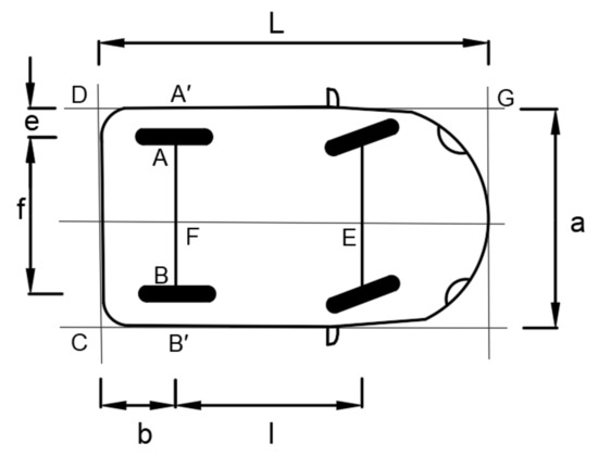
Figure 1.
Example of vehicle dynamics parameters.
3.3. Ackerman Model Turns to Analysis
The Ackerman–Jeantand steering system model (Ackerman–Jeantand) was proposed by Georg Lankensperger, a German carriage engineer, in 1817. The assumptions of the Ackerman–Jeantand model analysis are as follows: (1) there is no force or mass involved, and the car body is simplified as rigid; (2) the wheel undergoes pure rolling motion, without considering the sliding and sliding running state of the tire; (3) tire lateral deformation is proportional to the lateral force, without considering the nonlinearity of tire material and structure; and (4) the impact of vertical tire load changes as centrifugal force on the tire is not considered.
Veneri and others [19,20] have undertaken a great amount of research on the Ackerman steering principle and proved its applicability and reliability. In this paper, the parking speed of the vehicle in the underground parking lot is maintained at 5 km/h, and its steering process is a low-speed steady-state mode, which meets the Ackerman steering system model. All subsequent parking tracks are based on the assumption of the Ackerman steering system model.
3.4. A Single Parking Track
In this paper, we adopt the parking method of reversing into the parking space and driving out of the parking space. Its track is shown in Figure 2. The coordinate system is established with the short side of the top side of the parking space as the X-axis and the long side of the left side as the Y-axis. The initial parking position of the vehicle is perpendicular to the parking space. The right rear wheel B is taken as the vehicle reference point, and the horizontal and vertical distances of point B are u0 and v0. The process of parking is as follows: the vehicle turns left to the steering wheel at A1, and the minimum turning radius R that can be reached by the rear wheel is used as the track arc. The vehicle drives the P1 section around the center of the circle O1 at a low speed to the A2 point, and then reverses into the garage in the direction of the parking space on the Y axis in the positive direction and keeps the road running continuously in the process. The minimum turning radius R that can be reached by the rear wheels should be converted according to the minimum turning radius r of the vehicle.
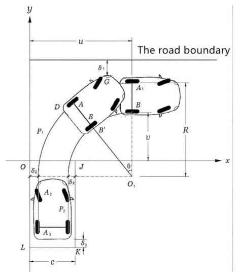
Figure 2.
Schematic diagram of one-stage vertical parking track.
In order to better determine the track of parking behavior and determine whether the obstacle can be avoided by the method of parking, the automatic track seeking algorithm is used to calculate several feature points of the vehicle. According to the kinematic model of parking, parking follows an arc motion, and the steering angle during parking is θ. Given that the initial position of point B is (u0,v0), coordinate values of other feature points can be deduced from geometric relations in Figure 2.
where, is the distance between A and D.
From the above expressions of A, B, D, and B’, it can be seen that if the initial position of the vehicle and the steering angle θ of the vehicle on the way to parking can be determined, the trajectory curve of the vehicle in the parking process can be drawn, and the applicability of the parking space can be judged according to the parking trajectory.
4. Parking Space Size Constraint Model
4.1. Spatial Constraint Feature Form
As the vehicle is subject to the above spatial constraints, the parking path trajectory of the vehicle is different from that of the barrier-free parking space, so it is necessary to measure the constraint collision that may occur in the process of vertical parking.
When a vehicle uses one-stage parking to park in a designated parking space in an open lane, three spatial collision constraints may occur with surrounding obstacles: the constrained collision between the G point of the left front of the vehicle and the lane boundary; the collision between the vehicle and the left and right side of the parking space O point, and J point boundary; the collision between the vehicle and the dimension line behind the parking space when entering the parking space along the Y axis direction. Only when the one-stage parking satisfies these three spatial constraints can it be an effective and comfortable parking operation.
4.2. The Constraint
By establishing the constraint model of the relationship between the collision point and the parking space boundary and the lane boundary in the process of parking, the comfort level, an abstract concept, can be transformed into a numerical value and presented intuitively. When the numerical result of the model is less than 0, it indicates that there is still space surplus between the collision-prone point and the constraint boundary at this position. The smaller the numerical value is, the larger the remaining space is and the higher the parking comfort is. When the numerical result of the model is greater than 0, it means that the collision-prone point at this position has collided with the constraint boundary. The larger the value is, the narrower the space is and the worse the parking comfort is. In this section, constraint models of the three positions most prone to collision are calculated by studying the constraint conditions of the collision-prone points.
4.2.1. Constraints on the Collision between the G Point and Road Boundary
As can be seen from Figure 2, parking movement is an arc length trajectory circle with O1 on the rear axle extension line as the center and the minimum turning radius of the rear wheel R as the length. When the vehicle body complies with the rigid body hypothesis in the simplified Ackerman steering model, the front G point also moves in concentric circles with the rear axle O1 point as the center and the distance between O1 and the G point as the radius, as shown in Figure 3.
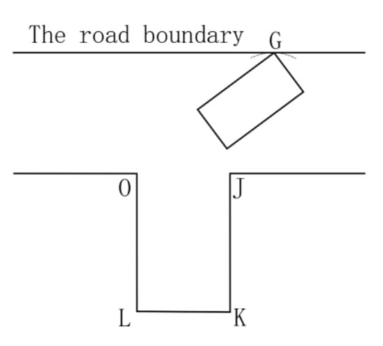
Figure 3.
Schematic diagram of the collision between the G point at the head and lane line.
According to the internal reference coordinate system of the car body, the dynamic coordinate value of G point changing with position can be derived:
where is the distance between points B and G.
The ordinate value of point G on the road boundary is W. To meet the spatial constraint of the collision point between the front and the lane, only the ordinate value of point G should always be smaller than the ordinate value of the lane, so:
Now, we substitute each coordinate point into the above equation.
To make the parameters more computable, the above equation is simplified. Since is small and negligible, then
Since the direction angle θ changes with the trajectory, it is necessary to eliminate and simplify θ, and when the maximum value of the equation on the left side is always less than zero, this constraint condition is proved to be valid. After adjusting both sides,
and .
In order to obtain the maximum value of the equation on the left, we find that when , we can take the maximum value of , and Equation (8) is also the maximum value. θ is a value from 0 to in the range of actual parking, which satisfies the maximum requirement and has a unique solution to make it maximum.
This constraint condition can be simplified as:
In Section 4, we need to compile an algorithm program based on the constraint equation. To facilitate the subsequent abbreviation and use of the constraint condition, the inequality on the left is denoted as an equation, and the equation on the left of the inequality is denoted as g(x).
4.2.2. Constraints on the Collision between the G Point and Road Boundary
In the process of entering the parking space, the vehicle is constrained by the dimensions of the three sides of the parking space. The collision of the dimensions of the right parking space is constrained by the outer contour point B’ of the right rear wheel and the vertex J of the parking space. However, when the turning radius of the vehicle is too large, a possible collision will occur with any point of the right parking space boundary OL. At the same time, when the car body goes back to the parking space, the rear contour line of the vehicle may collide with LK, and this distance can be controlled manually or by parking by wheels. Therefore, only the boundary collisions of the above two sizes are discussed and analyzed.
- ➀
- Constraint collision between the outer contour point B’ on the right side of the rear wheel and the vertex J of the parking space.
The width of the parking space is set as C. According to the analysis of the Ackerman steering model, when the vehicle enters the parking space along the extreme right angle during a one-stage parking operation, only the contour point B’ of the rear wheel will collide with the vertex J(c,0) of the parking space, as shown in Figure 4.
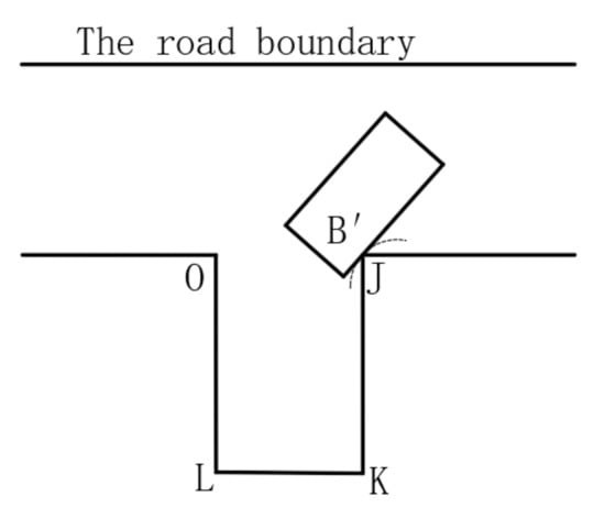
Figure 4.
Schematic diagram of collision with the J constraint on the right vertex of the parking space.
As can be seen from Figure 4, point B’ in the parking trajectory is a section of arc length with the vehicle’s instantaneous steering center O1(u0,v0 + F − R) as the center of the circle. Therefore, it only needs to ensure that the vertex J of the parking spot is always in the trajectory circle where O1B is located, so:
Similarly, the left-hand side of the inequality is f(x).
It should be noted that the minimum turning radius of the rear wheel of the vehicle is generally larger than the width of the lane, so the y-coordinate of the center of the instantaneous turning circle is generally negative. Therefore, when the vehicle completes the 90° rotation operation in advance in the lane of traffic, the constraint conditions above cannot be met.
- ➁
- Constraint collision between the left rear vertex D of the vehicle and the size line on the left side of the parking space.
As shown in Figure 5, the collision between the outer contour line of the vehicle and the left dimension line should meet two constraint conditions: (1) the constraint condition of point O of parking space exposure is satisfied; (2) a safe distance is kept from the size line on the left side after alignment.
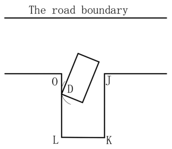
Figure 5.
Collision between the rear vertex and the dimension line on the left side of the parking space.
- (1)
- The driver enters the garage through the rearview mirror to judge whether the parking operation can be successfully completed by the two vertices O and J of the parking space exposure. Therefore, in order to avoid the spatial constraint of the parking space exposure O point, the distance between the instantaneous steering center O1 and O is always greater than the distance between O1 and D, namely
Coordinates of the left rear vertex D of the vehicle:
Substituting the coordinates of point D into Equation (13), and simplifying,
Similarly, the left-hand side of the inequality is m(x).
- (2)
- According to the provisions of “Code for Garage Building Design JGJ 100–2015”, after the vehicle enters the parking space and the car body is aligned at 90°, it keeps a safe distance from the size line of the parking space. Therefore, to determine whether this spatial constraint condition is satisfied, it should be considered that O1D does not touch the track in the X direction of the boundary dimension line when the vehicle steering angle reaches θ, namely:
Substituting all coordinate points into the above formula, we obtain:
In order to make the parameters easier to calculate, the above formula is simplified. Since is small and negligible, is made, and the maximum value of the above formula is obtained when . The simplified spatial constraint conditions are as follows:
Similarly, the left-hand side of the inequality is p(x).
5. Development of Automatic Calculation Program for Parking Comfort
Underground garage parking lots are characterized by a large number and close arrangement. Manual comfort testing for each parking lot is time-consuming and inefficient.
In four sections of this study, a parking parameter mathematical model of three factors of parking constraints was developed to quantify the concept of car parking comfort, and comfort parameters were put into constraint equations to determine whether a constraint equation was established. This program can obtain the relevant parameter information of each parking space and the location relationship between G, B’, and D collision points and the parking environment. It can process the constraint model data of each parking space in batches, score the deviation degree of the numerical model, and finally get the parking comfort score of each parking space.
Revit software is the BIM software with the largest market share in the construction industry at home and abroad. Meanwhile, it also provides a powerful secondary development interface. Therefore, in this paper, based on the BIM model of an underground garage, we use the C# programming language and carry out secondary program development of Revit to realize the rapid evaluation of the parking comfort of each parking space. See Figure 6 for specific development process.
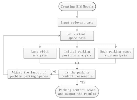
Figure 6.
Development flow chart of the quantitative analysis program for parking comfort.
In this paper, the “Element Instance” of the parking space diagram to be analyzed is obtained through the WPF user interaction interface. The location information of each parking space is matched, and rays are emitted in the designated directions around the location to capture the distance information of the obstacles hit by rays. The value of the constraint function is obtained by plugging it into the parking constraint model. According to the deviation degree of the constraint function value above and below point 0, the parking comfort degree of each parking space can be scored in combination with the built-in parking comfort scoring rules.
The main steps of program development are as follows:
- (1)
- Create a new project, set up the development environment, and design the program page (user interaction module), as shown in Figure 7.
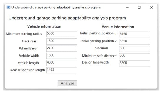 Figure 7. Program interface.
- (2)
- Obtain the coordinate point information of parking spaces and building environment information of the project.
The way to obtain the built environment information is through the ReferenceIntersector class, or ray algorithm, encapsulated in the RevitAPI assembly. ReferenceIntersector is a class for finding and returning elements that intersect rays created from target points and directions. By using this method, rays can be emitted from the target parking space and the coordinates of the intersection family with rays can be returned. By comparing the distance between the two coordinates, whether the building environment at the front of the parking space is open can be determined. The main algorithm is shown in Algorithm 1.
| Algorithm 1: Judge the position of obstacles in front of parking spaces. |
| The algorithm using Revit brings algorithm application RevitAPI and obtains all parking RevitAPIUI front obstacle distances Input: • array B[I] containing multiple parking family instances • number of parking family instances A Output: • array C[I] containing the distance between multiple parking family instances and obstacles in front of parking Spacesfor i←0 to A ParkXYZ←B[i].Location.XYZ if B[i].Y==1|| B[i].Y==−1 ObstacleXYZ← ReferenceIntersector(ElementFilter,FindReferenceTarget,View3D). FindNearest(ParkXYZ,ParkXYZ.Y).GetReference().GlobalPoint.XYZ end if if B[i].X==1|| B[i].X==−1 ObstacleXYZ← ReferenceIntersector(ElementFilter,FindReferenceTarget,View3D). FindNearest(ParkXYZ,ParkXYZ.X).GetReference().GlobalPoint.XYZ end if C[i]s←Line.CreateBound(ParkXYZ,ObstacleXYZ).Length end for |
- (3)
- Put relevant information into the constraint model equation described in the previous section to judge whether the parking spaces meet the constraints.
- (4)
- Integrate the comfort information of all parking spaces, highlight the parking spaces that are not up to the comfort standard, score the parking spaces in combination with the scoring system, output the relevant parking information, and determine the architectural environment reasons for the comfort level not being up to the standard.
6. Engineering Verification
The following figure shows the BIM model of the underground garage of a project in Shanghai. The construction area of the underground garage is 5956 square meters, the engineering design service life is 50 years, the seismic fortification intensity is 7 degrees, and the building fire resistance rating is level 1.
After detection by the parking adaptability analysis program, the program will highlight the parking spaces with poor comfort (see Figure 8) and output the information of the parking spaces that do not meet the requirements into Excel (see Table 1). It can be found that among the 474 common parking spaces in this parking area, there are 17 parking spaces with poor comfort scores. The main difficulty of the parking spaces is that the lane width is insufficient or limited when reverse parking, which leads to collisions with the road boundary when reversing around the minimum turning radius. Through the program checking calculation of this project example, it was also proved that the use of this program design method can quickly complete the analysis of hundreds of parking spaces, and greatly improve the efficiency of parking space planning and design and design quality.
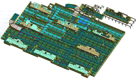
Figure 8.
Parking adaptability test results of an underground garage.

Table 1.
Value of the parking space constraint model with poor comfort.
7. Conclusions
In this paper, we put forward the concept of parking comfort, adopted the Ackerman steering model, considered the architectural environmental factors of parking spaces, established a constraint model in the parking process, and put forward a quantitative calculation and analysis method of parking comfort. In addition, using the secondary development technology of Revit, we developed a program to automatically calculate and detect the parking comfort of all parking spaces in the BIM model of underground garages, realizing the automatic calculation and discrimination of parking spaces, so as to put forward a fast, effective, and quantifiable calculation method of a parking comfort index for the design of parking spaces. We also examined an underground garage as a practical engineering case study. The feasibility and accuracy of the calculation model and program were thus verified.
Author Contributions
Methodology, C.L.; Writing—original draft, C.L.; Writing—review & editing, D.W. and C.L. All authors have read and agreed to the published version of the manuscript.
Funding
This research received no external funding.
Institutional Review Board Statement
Not applicable.
Informed Consent Statement
Not applicable.
Conflicts of Interest
The authors declare no conflict of interest.
References
- Zheng, C.; Li, L.; Chen, C. Discussion on Application of Intelligent Analysis of Parking Space based on BIM. Chongqing Archit. 2021, 7, 19–21. [Google Scholar]
- Xue, F. Research on problems in underground garage design. Informatiz. China Constr. 2017, 13, 69–71. [Google Scholar]
- Qiu, D.; Wu, B.; Gu, M.; Zhu, M. Hierarchical Control of Trajectory Planning and Trajectory Tracking for Autonomous Parallel Parking. IEEE Access 2021, 9, 94845–94861. [Google Scholar] [CrossRef]
- Li, H.; Guo, K.; Song, X.; Li, F. Trajectory planning of automatic parallel parking with multi-constraints based on Matlab. J. Cent. South Univ. Sci. Technol. 2013, 44, 101–107. [Google Scholar]
- Gao, Q.; Lu, Z.; Duan, C.; Xu, T. Research on Vehicle Vertical Parking Path Planning and Path Tracking. Automot. Eng. 2021, 43, 987–994+1012. [Google Scholar] [CrossRef]
- Ohama, Y.; Tanaka, K.; Yasuda, H.; Obata, K.; Fukumura, N. Improvements in Perpendicular Reverse Parking by Directing Drivers’ Preliminary Behavior. IEEE Access 2021, 9, 92003–92016. [Google Scholar] [CrossRef]
- Petrov, P.; Georgieva, V. Geometric path planning and tracking control with bounded steering angle for the parking problem of automatic vehicles. In Proceedings of the 4th International Conference on Materials Engineering And Nanotechnology (Icmen 2021), Bangkok, Thailand, 26–28 November 2021. [Google Scholar] [CrossRef]
- Song, J.; Dai, B.; Shan, E.; Sun, Z.; He, H. Trajectory planning approach of autonomous parallel parking with kinodynamic constraints. J. Cent. South Univ. Sci. Technol. 2009, 40, 135–141. [Google Scholar]
- Paromtchik, I.E. Steering and velocity commands for parking assistance. In Proceedings of the IASTED International Conference on Robotics and Applications, Marina Del Rey, CA, USA, 1–3 March 2004. [Google Scholar]
- Paromtchik, I.E.; Laugier, C. Autonomous Parallel Parking of Nonholonomic Vehicle. In Proceedings of the Conference on Intelligent Vehicles, Tokyo, Japan, 19–20 September 1996; pp. 13–18. [Google Scholar]
- Zhao, Y.; Collins, E.G. Robust automatic parallel parking in tight spaces via fuzzy logic. Robot. Auton. Syst. 2005, 51, 111–127. [Google Scholar] [CrossRef] [Green Version]
- Kim, D.; Chung, W.; Park, S. Practical motion planning for car-parking control in narrow environment. IET Control. Theory Appl. 2010, 4, 129–139. [Google Scholar] [CrossRef]
- Inoue, T.; Dao, M.Q.; Liu, K.Z. Development of an auto-parking system with physical limitations. In Proceedings of the SICE 2004 Annual Conference, Sapporo, Japan, 4–6 August 2004. [Google Scholar]
- Yang, H. Optimization of Parking Space in Commercial Complex. Master’s Thesis, Chongqing University, Chongqing, China, 2015. (In Chinese). [Google Scholar]
- Gu, J. The Study of Parking Space Planning Method Based on Drivers’ Behavior Characteristics. Master’s Thesis, Hefei University of Technology, Hefei, China, 2017. (In Chinese). [Google Scholar]
- Jin, J. The relationship between commercial underground parking space environment and human behavior psychology. J. Shandong Jiaotong Univ. 2011, 19, 82–86. [Google Scholar]
- Ma, X.; Zhou, C.; Gu, J. Effect of vertical parking space width and passage width on drivers’ parking behavior. Intell. City 2018, 4, 10–13. [Google Scholar] [CrossRef]
- Hashimoto, N.; Kato, S.; Tsugawa, S. A study on system for improving parking operation of elderly drivers -assistance and instruction. In Proceedings of the 2008 IEEE International Conference on Vehicular Electronics and Safety, Columbus, OH, USA, 22–24 September 2008. [Google Scholar]
- Veneri, M.; Massaro, M. The effect of Ackermann steering on the performance of race cars. Veh. Syst. Dyn. 2021, 59, 907–927. [Google Scholar] [CrossRef]
- Loffe, M.L. Ackermann Principle and its Implementation in Modern Cars. Mech. Eng. Mach. Sci. 2021, 9, 40–47. [Google Scholar] [CrossRef]
Publisher’s Note: MDPI stays neutral with regard to jurisdictional claims in published maps and institutional affiliations. |
© 2022 by the authors. Licensee MDPI, Basel, Switzerland. This article is an open access article distributed under the terms and conditions of the Creative Commons Attribution (CC BY) license (https://creativecommons.org/licenses/by/4.0/).