
Theory of Electrical Breakdown in a Nanocomposite Capacitor


Abstract
:1. Introduction
2. Methods
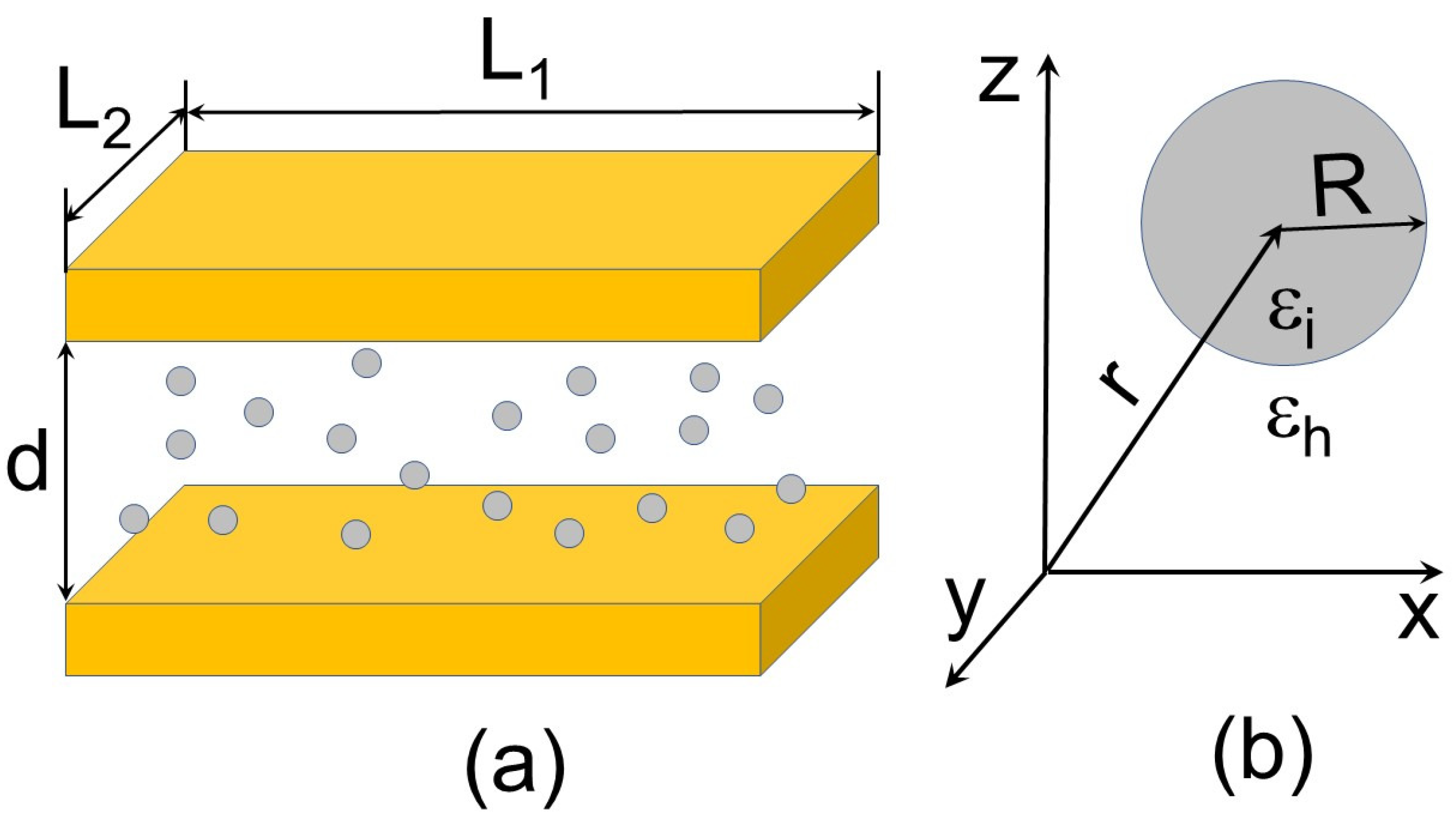
2.1. Model
2.2. Electrical Breakdown in Conventional Capacitors
2.3. Local Field in a Nanocomposite
3. Results
3.1. Breakdown Parameters in a Nanocomposite Capacitor
3.2. Maximum Energy Density
4. Comparison with Experiments and Discussion
5. Conclusions
Author Contributions
Funding
Institutional Review Board Statement
Informed Consent Statement
Data Availability Statement
Conflicts of Interest
References
- Li, H.; Liu, F.; Fan, B.; Ai, D.; Peng, Z.; Wang, Q. Nanostructured ferroelectric-polymer composites for capacitive energy storage. Small Methods 2018, 2, 1700399. [Google Scholar] [CrossRef]
- Cao, Y.; Irwin, P.C.; Younsi, K. The future of nanodielectrics in the electrical power industry. IEEE Trans. Dielectr. Electr. Insul. 2004, 11, 797–807. [Google Scholar]
- Dang, Z.-M.; Yuan, J.-K.; Zha, J.-W.; Zhou, T.; Li, S.-T.; Hu, G.-H. Fundamentals, processes and applications of high-permittivity polymer-matrix composites. Prog. Mater. Sci. 2012, 57, 660–723. [Google Scholar] [CrossRef]
- Dang, Z.-M.; Yuan, J.-K.; Yao, S.-H.; Liao, R.-J. Flexible nanodielectric materials with high permittivity for power energy storage. Adv. Mater. 2013, 25, 6334–6365. [Google Scholar] [CrossRef]
- Prateek Thakur, V.K.; Gupta, R.K. Recent progress on ferroelectric polymer-based nanocomposites for high energy density capacitors: Synthesis, dielectric properties, and future aspects. Chem. Rev. 2016, 116, 4260–4317. [Google Scholar] [CrossRef]
- Rajib, M.; Shuvo, M.A.I.; Karim, H.; Delfin, D.; Afrin, S.; Lin, Y. Temperature influence on dielectric energy storage of nanocomposites. Ceram. Int. 2015, 41, 1807–1813. [Google Scholar] [CrossRef]
- Kim, P.; Doss, N.M.; Tillotson, J.P.; Hotchkiss, P.J.; Pan, M.-J.; Marder, S.R.; Li, J.; Calame, J.P.; Perry, J.W. High energy density nanocomposites based on surface-modified BaTiO3 and a ferroelectric polymer. ACS Nano 2009, 3, 2581–2592. [Google Scholar] [CrossRef]
- Grabowski, C.A.; Fillery, S.P.; Koerner, H.; Tchoul, M.; Drummy, L.; Beier, C.W.; Brutchey, R.L.; Durstock, M.F.; Vaia, R.A. Dielectric performance of high permitivity nanocomposites: Impact of polystyrene grafting on BaTiO3 and TiO2. Nanocomposites 2016, 2, 117–124. [Google Scholar] [CrossRef] [Green Version]
- Smith, R.C.; Liang, C.; Landry, M.; Nelson, J.K.; Schadler, L.S. The mechanisms leading to the useful electrical properties of polymer nanodielectrics. IEEE Trans. Dielectr. Electr. Insul. 2008, 15, 187–196. [Google Scholar] [CrossRef]
- Dou, X.; Liu, X.; Zhang, Y.; Feng, H.; Chen, J.-F.; Du, S. Improved dielectric strength of barium titanate-polyvinylidene fluoride nanocomposite. Appl. Phys. Lett. 2009, 95, 132904. [Google Scholar] [CrossRef]
- Bi, K.; Bi, M.; Hao, Y.; Luo, W.; Cai, Z.; Wang, X.; Huang, Y. Ultrafine core-shell BaTiO3@SiO2 structures for nanocomposite capacitors with high energy density. Nano Energy 2018, 51, 513–523. [Google Scholar] [CrossRef]
- Zhou, Y.; Yuan, C.; Wang, S.; Zhu, Y.; Cheng, S.; Yang, X.; Yang, Y.; Hu, J.; He, J.; Li, Q. Interface-modulated nanocomposites based on polypropylene for high-temperature energy storage. Energy Storage Mater. 2020, 28, 255–263. [Google Scholar] [CrossRef]
- Cheng, L.; Liu, W.; Zhang, Z.; Zhou, Y.; Li, S. Enhanced breakdown strength and restrained dielectric loss of polypropylene/maleic anhydride grafted polypropylene/core-shell ZrO2@SiO2 nanocomposites. Polym. Compos. 2022, 43, 2175–2183. [Google Scholar] [CrossRef]
- Maxwell Garnett, J.C. Colours in metal glasses and in metallic films. Phil. Trans. R. Soc. A 1904, 203, 385–420. [Google Scholar]
- Markel, V.A. Introduction to the Maxwell Garnett approximation: Tutorial. J. Opt. Soc. Am. A 2016, 33, 1244–1256. [Google Scholar] [CrossRef] [PubMed] [Green Version]
- Bordo, V.; Ebel, T. How to determine the capacitance of a nanocomposite capacitor. AIP Adv. 2022, 12, 045107. [Google Scholar] [CrossRef]
- Forlani, F.; Minnaja, N. Thickness influence in breakdown phenomena of thin dielectric films. Phys. Stat. Sol. 1964, 4, 311–324. [Google Scholar] [CrossRef]
- Nordheim, L. Zur Theorie der thermischen Emission und der Reflexion von Elektronen an Metallen. Z. Phys. 1928, 46, 833–855. [Google Scholar] [CrossRef]
- Fowler, R.H.; Nordheim, L. Electron emission in intense electric fields. Proc. R. Soc. A 1928, 119, 173–181. [Google Scholar]
- Schmidlin, F.W. Enhanced tunneling through dielectric films due to ionic defects. J. Appl. Phys. 1966, 37, 2823–2832. [Google Scholar] [CrossRef]
- Nha, H.; Jhe, W. Cavity quantum electrodynamics between parallel dielectric surfaces. Phys. Rev. A 1996, 54, 3505–3513. [Google Scholar] [CrossRef] [PubMed]
- Stratton, J.A. Electromagnetic Theory; McGraw-Hill: New York, NY, USA, 1941; p. 206. [Google Scholar]
- Born, M.; Wolf, E. Principles of Optics, 6th ed.; Pergamon Press: Oxford, UK, 1980; p. 100. [Google Scholar]
- Bordo, V.G. Local field in finite-size metamaterials: Application to composites of dielectrics and metal nanoparticles. Phys. Rev. B 2018, 97, 115410. [Google Scholar] [CrossRef] [Green Version]
- Wylie, J.M.; Sipe, J.E. Quantum electrodynamics near an interface. Phys. Rev. A 1984, 30, 1185–1193. [Google Scholar] [CrossRef]
- Bordo, V.G. Self-excitation of surface plasmon polaritons. Phys. Rev. B 2016, 93, 155421. [Google Scholar] [CrossRef] [Green Version]
- Sipe, J.E. The ATR spectra of multipole surface plasmons. Surf. Sci. 1979, 84, 75–105. [Google Scholar] [CrossRef]
- Sipe, J.E. The dipole antenna problem in surface physics: A new approach. Surf. Sci. 1981, 105, 489–504. [Google Scholar] [CrossRef]
- Bordo, V.G. Dicke superradiance from a plasmonic nanocomposite slab. J. Opt. Soc. Am. B 2021, 38, 2104–2111. [Google Scholar] [CrossRef]
- Bajac, B.; Vukmirović, J.; Tripković, D.; Djurdjić, E.; Stanojev, J.; Cvejić, Ž.; Škorić, B.; Srdić, V.V. Structural characterization and dielectric properties of BaTiO3 thin films obtained by spin coating. Process. Appl. Ceram. 2014, 8, 219–224. [Google Scholar] [CrossRef]
- Wang, S.; Liu, L.; Zeng, Y.; Zhou, B.; Teng, K.; Ma, M.; Chen, L.; Xu, Z.J. Improving dielectric properties of poly(vinylidene fluoride) composites: Effects of surface functionalization of exfoliated graphene. Adhes. Sci. Technol. 2015, 29, 678–690. [Google Scholar] [CrossRef]
- Goswami, A.K. Dielectric properties of unsintered barium titanate. J. Appl. Phys. 1969, 40, 619–624. [Google Scholar] [CrossRef]
- Hoshina, T. Size effect of barium titanate: Fine particles and ceramics. J. Ceram. Soc. Jpn. 2013, 121, 156–161. [Google Scholar] [CrossRef] [Green Version]

Publisher’s Note: MDPI stays neutral with regard to jurisdictional claims in published maps and institutional affiliations. |
© 2022 by the authors. Licensee MDPI, Basel, Switzerland. This article is an open access article distributed under the terms and conditions of the Creative Commons Attribution (CC BY) license (https://creativecommons.org/licenses/by/4.0/).
Share and Cite
Bordo, V.; Ebel, T. Theory of Electrical Breakdown in a Nanocomposite Capacitor. Appl. Sci. 2022, 12, 5669. https://doi.org/10.3390/app12115669
Bordo V, Ebel T. Theory of Electrical Breakdown in a Nanocomposite Capacitor. Applied Sciences. 2022; 12(11):5669. https://doi.org/10.3390/app12115669
Chicago/Turabian StyleBordo, Vladimir, and Thomas Ebel. 2022. "Theory of Electrical Breakdown in a Nanocomposite Capacitor" Applied Sciences 12, no. 11: 5669. https://doi.org/10.3390/app12115669
APA StyleBordo, V., & Ebel, T. (2022). Theory of Electrical Breakdown in a Nanocomposite Capacitor. Applied Sciences, 12(11), 5669. https://doi.org/10.3390/app12115669