Article

Magnetic Field Effect on the Handedness of Electrodeposited Heusler Alloy

1
Department of Chemistry “Ugo Schiff”, University of Florence, Via della Lastruccia 3, 50019 Sesto Fiorentino, Italy
2
National Interuniversity Consortium of Materials Science and Technology (INSTM), Via G. Giusti 9, 50121 Firenze, Italy
3
Department of Physics, FIM, University of Modena, Via Campi 213/A, 41125 Modena, Italy
4
Department of Engineering “Enzo Ferrari” (DIEF), University of Modena, Via Vivarelli 10, 41125 Modena, Italy
*
Author to whom correspondence should be addressed.
Appl. Sci. 2022, 12(11), 5640; https://doi.org/10.3390/app12115640
Submission received: 9 May 2022 / Revised: 24 May 2022 / Accepted: 31 May 2022 / Published: 1 June 2022

Abstract

:
Magneto-electrochemistry (MEC) experiments were carried out in the electrodeposition of a ferromagnetic Heusler alloy. The electrodeposition was carried out in the absence (as a reference) and in the presence of a magnetic field that was applied perpendicularly to the electrode–solution interface. The obtained metallic deposit was characterized by SEM-EDS, XRF, and XRD techniques. The ferromagnetic properties are assessed on the basis of SQUID measurements. The experimental results indicate that the influence of the presence of the magnetic field induces differences in the electrochemical measurements and a macroscopic handedness (chirality) in the deposit, which is a function of magnet orientation. Eventually, the coercivity of the Heusler alloy that was obtained in the presence of the magnetic field was larger compared to that of the deposit that was obtained without a magnetic field.

1. Introduction

In magneto-electrochemistry (MEC), electrochemical experiments are carried out with the application of a magnetic field in the electrochemical cell. Synergic effects are observed upon changing the superimposition direction of the electric and magnetic fields, causing complex hydrodynamics conditions in the cell, as well as the emergence of unique electronic properties in both bulk reagents and electrodes [1]. From a historical point of view, Michael Faraday observed for the first time the effect of the magnetic field intensity and direction on electrochemical process [2]. Nonetheless, MEC experiments form a limited niche and rarely addressed the measurement procedure.
The synthesis of new compounds that allow the modulation of the magnetic field is a hot topic [3,4]. Fairly elegant and interesting papers are present in the literature which aim to assess the effect of a magnetic field on both bulk and interfacial properties in electrochemical systems. The interesting results report on the “chiral texture” that is observed in electrodeposited films grown under the influence of an applied magnetic field: metals (Cu, Ag, Fe, etc.); alloys; and conducting polymers (polyaniline, etc.). Such chiral structures are useful in technological applications such as enantio-selective recognition processes [5,6].
So far, most of the studies in the literature have used an external magnetic field to generate chiral structures or special hydrodynamic conditions. Of late, Naaman et al., discovered a revolutionary “chiral induced spin selectivity (CISS)” effect: the electron transmission through chiral systems depends on the spin, giving rise to a net magnetic moment (with the associated magnetic field) [7], and references therein cited. The idea was recently demonstrated via an innovative Hall device that serves as the working electrode in an electrochemical cell, and is able to give information on the correlation of spin selectivity and the electrochemical process without an externally applied magnetic field [8].
This article aims to explore the effect of applying a magnetic field during massive electrochemical deposition (the metallic deposit has a thickness in the 350 to 450 nm range) of a Heusler alloy. The Heusler alloy is a family of magnetic compounds with a face-centred cubic crystal structure and formula X2YZ, where X and Y are transition metals and Z is a p-block element [9,10]. The Heusler alloy is interesting for many applications from data storage [11] to spintronics [12]. In this work, we performed the electrodeposition of the Co-Fe-Sn system that was previously obtained galvanostatically [13,14] and potentiostatically [15] by other authors in the absence of an external magnetic field.

Magnetic Effect in Electrochemistry

The experimental results that were obtained in the field of magneto-electrochemistry can be rationalized based on classical electromagnetism laws. The electrostatic force acting on the ions of charge q , in solution, is given by Equation (1) and (2). The latter allow to rationalize the effect of the magnetic field on the electrolyte conductivity, featuring ion migration under a given applied electric field E. With the simultaneous presence of a magnetic field B, which yields a Lorentz type force, on the moving ion of charge q [15,16]:
F = q E
F = q E + v × B
where v is the speed of the ion in the electrolyte solution. Equation (2) represents the deviation of the motion of ions from a simple linear trajectory [17]. The Lorentz force is maximized when the current and magnetic field are perpendicular and minimized when they are parallel. On the whole, the observed experimental behaviour is addressed as the magneto-hydrodynamics (MHD) effect [18]. Further on, Equation (3) gives due reason to the force acting on a moving ion in a non-uniform magnetic field [1]:
F m a g = χ m B 2 c 2 μ 0 + χ m c 0 B B μ 0
In Equation (3) χ m is the molar magnetic susceptibility, μ 0 is the free space permeability, and c 0 is the bulk concentration of the magnetic species. This expression of F m a g consists of two terms: the first term of the right-hand side of Equation (3) is the paramagnetic gradient force (which depends on the gradient of the concentration); the second term in Equation (3) is the field gradient force (which can be significant even in the case of a uniform magnetic field: it can be found close to the rough surface of a ferromagnetic electrode). Note that Equations (1)–(3) do not account for any spin related effect, as well as any symmetry related effect, or spin-chirality interaction. Application of a magnetic field on the bulk electrolyte mass transport can be rationalized within such a classical based approach [19]. Indeed, the application of a magnetic field in the electro-deposition yields chiral patterns of either clockwise or anticlockwise handedness, depending on the magnetic field orientation with respect to the electrode surface [20]. The inhomogeneity due to the confinement of the electrode and the size of the magnet could generate vortexes all around the electrode, and even smaller vortices on the electrodeposited asperities [21]. For this reason, even when the current and magnetic field are nominally parallel, numerous works have found that the inherent inhomogeneity (e.g., edge effects) of electrodes and magnets can lead to local variations in both current and magnetic field, resulting in significant and complex convective flows [16]. Furthermore, X-ray diffraction (XRD) and scanning electron microscopy (SEM) analyses proved the occurrence of modifications in the deposited chemical composition, and in the surface roughness as well, of an electrodeposition process that was carried out in the presence of a magnetic field [22]. Similar results are observed in the electropolymerization of organic compounds too, where asymmetric induction is observed in the polyaniline electropolymerization under high magnetic fields [23]. The importance of these studies rests in the possible use of these materials as catalysts and sensors in the field of enantiorecognition [24,25,26,27,28,29,30,31,32].

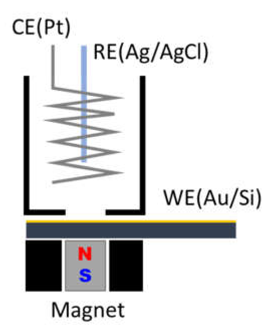
2. Materials and Methods
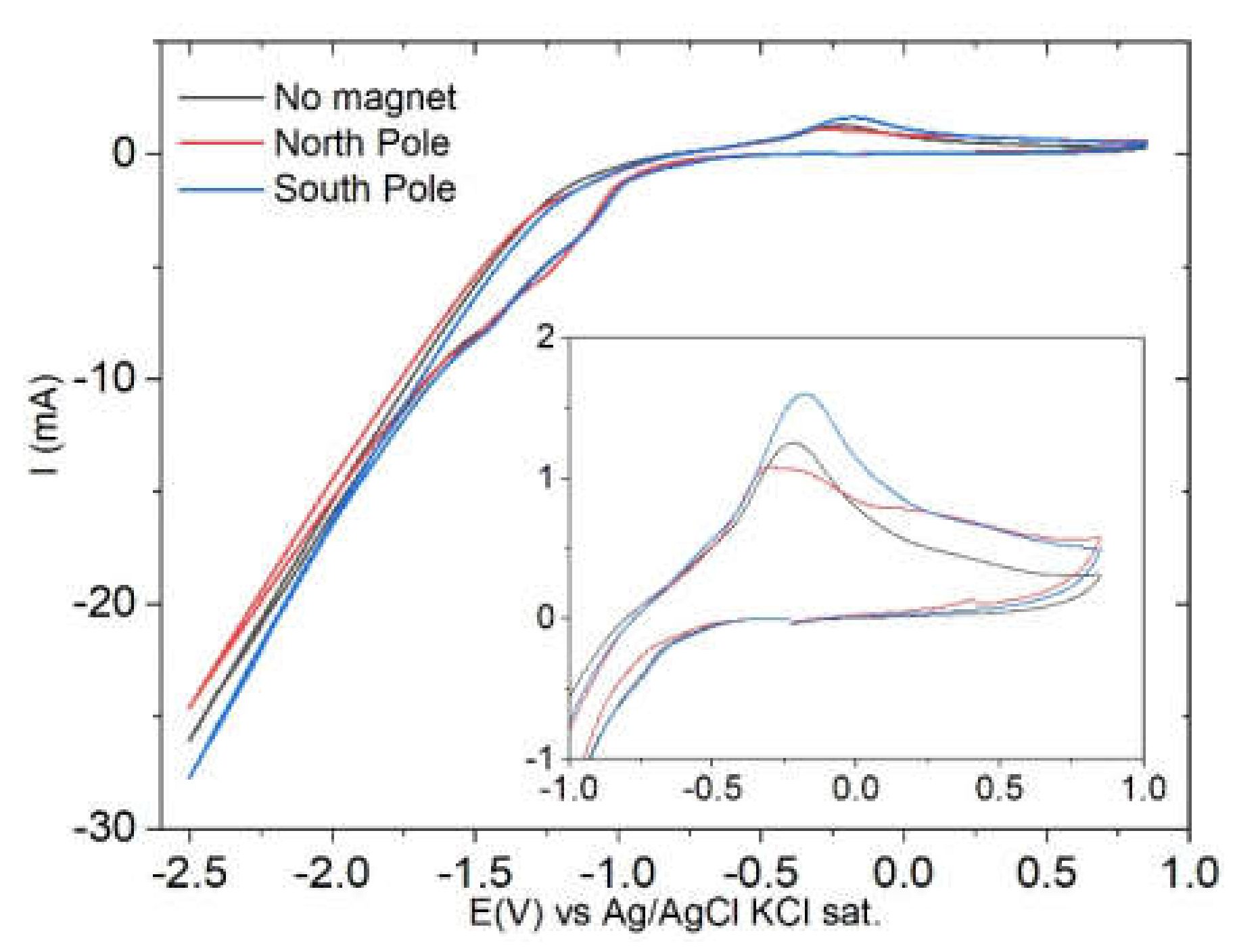
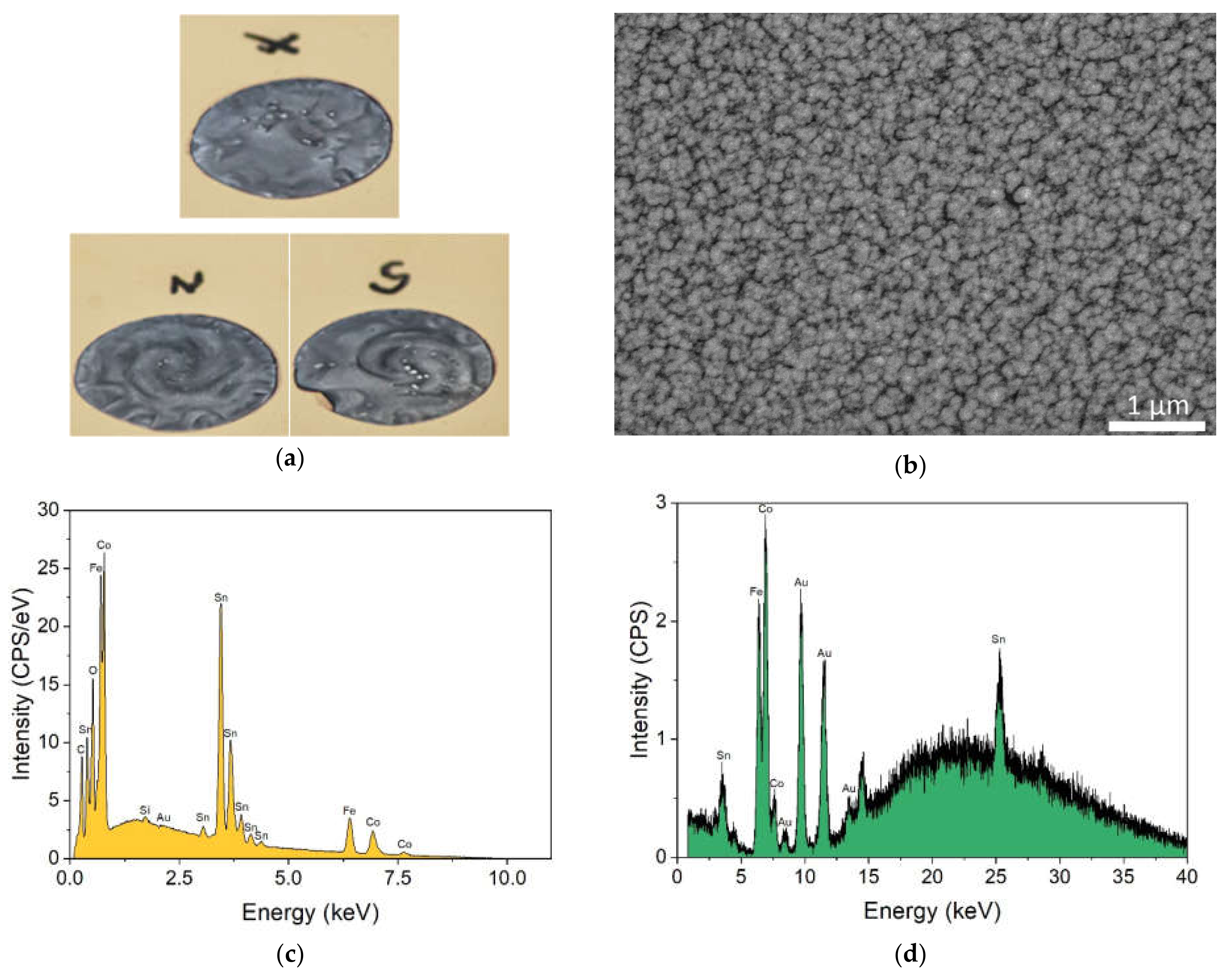
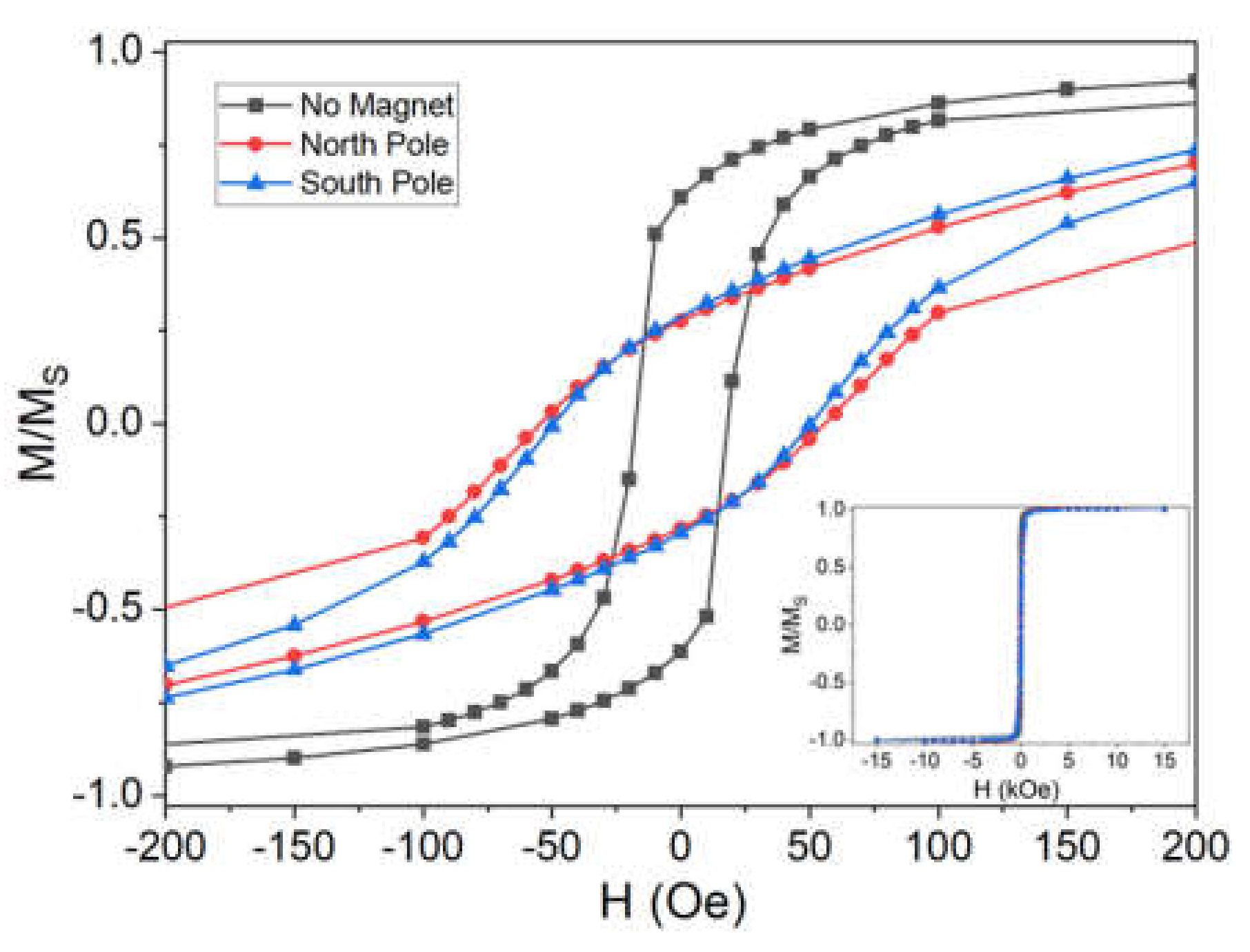
We chose to investigate Co2FeSn Heusler alloy that was prepared galvanostatically. To prepare the sample, the composition of the solution was based on the work of Watanabe et al. [15] which consisted of: CoSO4 75 mM; FeSO4 50 mM; SnSO4 8.3 mM; sodium D(+)-gluconate 120 g/L; tryptone (peptone from casein) 0.1 g/L; L(+)-ascorbic acid stabilizer 2 g/L; NaCl 0.3 M; and boric acid 0.3 M. Besides the metal precursors, gluconate is used as a complexing agent toward tin; ascorbic acid as a stabilizing agent; peptone as a brightener; NaCl as the supporting electrolyte; and boric acid as the buffer. We have found that the sequence of solution preparation is important in bringing all the components into the solution. Initially, the ascorbic acid solution was prepared with sodium gluconate, then the metals’ salts were added one by one starting with tin sulphate and waiting until the complete dissolution before proceeding with the next salt. The dissolution was facilitated by using an ultrasonic bath. Then, tryptone, NaCl, and boric acid were added in this order. Finally, the pH of the solution was raised to 7 using NaOH. The fresh solution has a burgundy colour but tends to age quickly producing a brown colour. The solution was kept at 60 °C during the measurements and depositions.
The electrochemical measurements were conducted with a three-electrode setup: the working electrode (WE) was a commercial (100) silicon wafer at 1 mm thick and coated with ≈ 100 nm of gold. The adhesion layer between Si and Au was made of ≈ 5 nm of Ti to avoid interferences during the magnetic measurements. The electrode was flame annealed before the measurements and depositions to rearrange the crystalline structure of gold from monocrystalline to (111) [33]. Ag/AgCl sat. KCl was used as a reference electrode (RE) and a platinum mesh as a counter electrode (CE).
The electrochemical cell (Figure 1) is a cylinder with a diameter of 2.2 cm and a height of 2.2 cm. On the bottom of the cell is a hole of 8.5 mm in diameter where the WE is in contact with the solution. The total amount of solution in the cell was ≈ 8 mL. There is a plastic support under the WE to house the magnet.
A D66-N52 magnet (K&J magnetics, Inc., Pipersville, PA, USA) was used for the measurements by placing it below the electrochemical cell. The magnet is 3/8″ in diameter and 3/8″ thick, NdFeB Grade N52, with a surface field of 6619 Gauss. This value is high enough ensuring to work in a magnetic field that is higher than the saturation magnetization of the electrodeposited compound (980 emu/cm3) [34].
Scanning electron microscopy (SEM-EDS) images and microanalysis were acquired using a Hitachi SU3800 that was equipped with an Ultim Max 40 Analytical Silicon Drift EDS Detector using an accelerating voltage of 10 kV.
XRF spectra were acquired with a Bowman BA-100 using 50 kV tube voltage, a 0.8 mA current tube, a 0.6 mm collimator diameter, and a 0.5 mm Al filter in air.
Spectra were collected using the larger collimator (10 mm) to achieve better counting statistics since no restrictions were related to sample geometry; the acquisition time was set to 60 s as a trade-off between accuracy and duration of the measurement session. Powder X-ray Diffraction (PXRD) patterns were recorded on a Bruker New D8 Advance DAVINCI diffractometer using Cu Kα radiation (λ =1.540 Å), a 0.6 mm Ni collimator and 0.02 mm Ni filter, a fast multichannel energy-discriminator detector, and a flat holder. Patterns were obtained by using a Bragg-Brentano configuration in the θ/2θ 30°–90° range.
Field-dependent direct current (DC) magnetic measurements were conducted on a Quantum Design MPMS SQUID magnetometer at 5 K, with the field oriented parallel to the plane of the sample.

3. Results

Cyclic voltammetry on the solution containing the metal ions was performed between 0.85 V and −2.5 V with a scan rate of 50 mV/s. The results, reported in Figure 2 indicate that the deposition of the metals occurs together with the hydrogen evolution starting from −1 V. An anodic peak assigned to the oxidation of the alloy is present at −0.2 V.
When we locate the south pole of the magnet below the electrode (i.e., the magnetic field is applied downward on the solution), both the peak related to the evolution of hydrogen and the anodic peak show higher currents (in absolute value) with respect to the measurement that was performed without the magnet. The opposite situation holds when the north pole of the magnet is placed below the electrode (i.e., the magnetic field is applied upward). The variation in the current intensity on varying the magnetic field configuration suggests that the presence of a chiral species (D(+)-gluconate) in solution combined with the presence of a magnetic field may lead to the CISS effect. A confirmation of this hypothesis would require carrying out the experiment in the presence of the opposite enantiomer (l(−)-gluconate); however, this is beyond the scope of this paper.
The Heusler alloy thick film samples were prepared in galvanostatic mode imposing a current density of 2.5 A/dm2, which produced the best deposition according to Duan and Kou [14]. During the galvanostatic deposition, the applied potential varied around the value of −1.9 V. The deposition process was carried out either in the absence of a magnet or in the presence of north and south magnetic fields. The value of the Lorentz force in our experimental setup is roughly FL = 125 Nm−3, considering that the magnetic field at a distance of 1 mm (the thickness of the silicon wafer) from the surface of the magnet was approximately B = 0.5 T and the current density j = 2.5 Adm−2. On the samples that were deposited under magnetic field, a chiral spiral structure developed Figure 3a): a left-handed spiral was present when the north pole of the magnet was under the electrode; on the other hand, a right-handed spiral appeared in the case of the south pole.
The samples were characterised morphologically and compositionally with SEM-EDS. No significative differences were detected in the three different samples. In Figure 3 SEM-EDS and XRF analysis of the sample without a magnet were reported by way of example. The SEM analysis (Figure 3b) shows the presence of growth nuclei with dimensions between 100 nm and 200 nm. The EDS analysis (Figure 3c) provides the composition of the coating: 29.8 wt% Co, 24.5 wt% Fe, and 45.7 wt% Sn were found, which correspond to a Co:Fe:Sn stoichiometric ratio of 2.0:1.7:1.5. A cobalt deficiency was found that was relative to the expected amount 2:1:1.
The composition that was found with EDS was used to obtain the thickness of the deposit from the XRF spectra (Figure 3d), following a procedure that was previously described in [35,36,37]. The mean thickness of the sample that was prepared without the magnet was 0.46 µm; the sample on the south pole of the magnet had a thickness of 0.36 µm, while the sample on the north pole was 0.34 µm.
The Au-Si substrate and the samples with the deposit were analysed with XRD (Figure 4). In the substrate, two strong peaks of Au (111) and (222) are present at 38.4° and 82.0°, and a broad and weak peak of the underlying Si (400) is also visible at approximately 69°. The samples that were prepared in the same electrochemical conditions under different magnetic configurations do not show any differences between them. Compared to the substrate, only one additional peak at 2 θ = 43.8° is observed. This corresponds to Co-Fe-Sn (110) [14,15]; on the contrary, the (211) reflection of Co-Fe-Sn that was expected at 2 θ = 82° is not observed, most probably because it was covered by the (222) reflection of the gold substrate. No reflections were observed at 2 θ = 30.4°, corresponding to an excess of Co3Sn2 as found by Duan and Kou [14]. At the same time, no additional signal of a possible excess of iron and tin was detected.
The magnetic properties of the samples were evaluated by SQUID measurements at 5 K. A closed view of the hysteresis loops that were normalized with respect to MS is reported in Figure 5, and from it we evaluate the coercivity of the samples. In this case, the samples obtained using the magnet produces values that are similar one to the other (north pole 110 Oe, South pole 100 Oe), while in the sample without magnet the HC is considerably lower (36 Oe). Based on these results, the coercivity is clearly larger when a magnetic field is applied. Coercivity is affected by both the content in the films and the number of defects (the higher the number of defects, the higher the coercivity). In this respect, these results suggest that the magnetic field influences the growth and the possible presence of an impurity phase.

4. Conclusions

In this work, the electrodeposition process of a Heusler type alloy in the presence of a magnetic field is shown to be characterized by a marked difference in both the deposit handedness (morphology). The presence of the magnetic field is able to induce handedness in the bulk deposit. This was proved by the SEM images which revealed spiral spatial patterns with opposite handedness for opposite magnetic field configuration. The obtained alloys showed ferromagnetic properties. Bulk ferromagnetic properties are characterized by an increase in the coercivity value between the deposit obtained without magnetic field application, with respect to the deposit obtained when applying the magnetic field. In this lab, we are currently involved in studying the mechanism underlying the observed handedness as a function of the applied magnetic field, as well as possible applications of the so-prepared chiral in both the sensor and spintronics field.

Author Contributions

Conceptualization, C.F.; investigation, W.G., M.V., F.P., M.B., M.S., L.S. and A.S.; data curation, W.G.; writing—original draft preparation, W.G. and C.F.; writing—review and editing, W.G. and C.F.; supervision, C.F.; project administration, C.F. and M.I.; funding acquisition, M.I. All authors have read and agreed to the published version of the manuscript.

Funding

This research was funded by the Regione Toscana POR CreO FESR 2014–2020—Azione 1.1.5 sub-azione a1—Bando 1 “Progetti Strategici di ricerca e sviluppo”, which made possible the projects “Innovativi processi di produzione a basso impatto ambientale di catene in acciaio e alluminio” (ACAL 4.0), CUP 3553.04032020.158000165_1385, CIPE D14E20006260009, and “Arte, Moda e arredo in un Processo Elettrochimico innovativo con controllo da Remoto 4.0—Circular Ecofriendly” (A.M.P.E.R.E.), CUP 3553.04032020.158000223_1538, CUP CIPE D14E20006370009. The authors also acknowledge the MIUR-Italy for “Progetto Dipartimenti di Eccellenza 2018–2022” allocated to the Department of Chemistry “Ugo Schiff” of the University of Firenze, Italy.

Institutional Review Board Statement

Not applicable.

Informed Consent Statement

Not applicable.

Data Availability Statement

Not applicable.

Acknowledgments

The authors acknowledge MatchLab Interdepartmental Research Unit, Università degli Studi di Firenze for the support.

Conflicts of Interest

The authors declare no conflict of interest.

References

  1. Coey, J.M.D.; Hinds, G. Magnetoelectrolysis—The effect of magnetic fields in electrochemistry. In Proceedings of the 5th International Pamir Conference, Ramatuelle, France, 16–20 September 2002; pp. 1–7. [Google Scholar]
  2. Fahidy, T.Z. Magnetoelectrolysis. J. Appl. Electrochem. 1983, 13, 553–563. [Google Scholar] [CrossRef]
  3. Zhang, Y.; Zhu, J.; Li, S.; Zhang, Z.; Wang, J.; Ren, Z. Magnetic properties and promising magnetocaloric performances in the antiferromagnetic GdFe2Si2 compound. Sci. China Mater. 2022, 65, 1345–1352. [Google Scholar] [CrossRef]
  4. Hu, L.; Cao, L.; Li, L.; Duan, J.; Liao, X.; Long, F.; Zhou, J.; Xiao, Y.; Zeng, Y.-J.; Zhou, S. Two-dimensional magneto-photoconductivity in non-van der Waals manganese selenide. Mater. Horizons 2021, 8, 1286–1296. [Google Scholar] [CrossRef] [PubMed]
  5. Bund, A.; Koehler, S.; Kuehnlein, H.H.; Plieth, W. Magnetic field effects in electrochemical reactions. Electrochim. Acta 2003, 49, 147–152. [Google Scholar] [CrossRef]
  6. Fahidy, T.Z. Characteristics of surfaces produced via magnetoelectrolytic deposition. Prog. Surf. Sci. 2001, 68, 155–188. [Google Scholar] [CrossRef]
  7. Naaman, R.; Waldeck, D.H. Chiral-Induced Spin Selectivity Effect. J. Phys. Chem. Lett. 2012, 3, 2178–2187. [Google Scholar] [CrossRef]
  8. Kumar, A.; Capua, E.; Kesharwani, M.K.; Martin, J.M.L.; Sitbon, E.; Waldeck, D.H.; Naaman, R. Chirality-induced spin polarization places symmetry constraints on biomolecular interactions. Proc. Natl. Acad. Sci. USA 2017, 114, 2474–2478. [Google Scholar] [CrossRef] [Green Version]
  9. Yin, M.; Hasier, J.; Nash, P. A review of phase equilibria in Heusler alloy systems containing Fe, Co or Ni. J. Mater. Sci. 2016, 51, 50–70. [Google Scholar] [CrossRef]
  10. Graf, T.; Parkin, S.S.P.; Felser, C. Heusler Compounds—A Material Class With Exceptional Properties. IEEE Trans. Magn. 2011, 47, 367–373. [Google Scholar] [CrossRef]
  11. Bai, Z.; Shen, L.; Han, G.; Feng, Y.P. Data storage: Review of heusler compounds. Spin 2012, 2, 1230006. [Google Scholar] [CrossRef] [Green Version]
  12. Elphick, K.; Frost, W.; Samiepour, M.; Kubota, T.; Takanashi, K.; Sukegawa, H.; Mitani, S.; Hirohata, A. Heusler alloys for spintronic devices: Review on recent development and future perspectives. Sci. Technol. Adv. Mater. 2021, 22, 235–271. [Google Scholar] [CrossRef] [PubMed]
  13. Chisholm, C.; Kuzmann, E.; El-Sharif, M.; Doyle, O.; Stichleutner, S.; Solymos, K.; Homonnay, Z.; Vértes, A. Preparation and characterisation of electrodeposited amorphous Sn–Co–Fe ternary alloys. Appl. Surf. Sci. 2007, 253, 4348–4355. [Google Scholar] [CrossRef]
  14. Duan, J.; Kou, X. Effect of Current Density on the Microstructure and Magnetic Properties of Electrodeposited Co2FeSn Heusler Alloy. J. Electrochem. Soc. 2013, 160, D471–D475. [Google Scholar] [CrossRef]
  15. Watanabe, N.; Sano, K.; Tasugi, N.; Yamaguchi, T.; Yamamoto, A.; Ueno, M.; Sumiyoshi, R.; Arakawa, T.; Koiwa, I. Preparation of Co2FeSn Heusler alloys by electrodeposition method. APL Mater. 2015, 3, 041804. [Google Scholar] [CrossRef]
  16. Monzon, L.M.A.; Coey, J.M.D. Magnetic fields in electrochemistry: The Lorentz force. A mini-review. Electrochem. Commun. 2014, 42, 38–41. [Google Scholar] [CrossRef]
  17. Yu, P.Y.; Cardona, M. Fundamentals of Semiconductors; Graduate Texts in Physics; Springer: Berlin/Heidelberg, Germany, 2010; ISBN 978-3-642-00709-5. [Google Scholar]
  18. Alfvén, H. Existence of Electromagnetic-Hydrodynamic Waves. Nature 1942, 150, 405–406. [Google Scholar] [CrossRef]
  19. Rhen, F.M.F.; Coey, J.M.D. Magnetic field effect on autocatalysis: Ag and Cu in concentrated nitric acid. J. Phys. Chem. B 2006, 110, 6274–6278. [Google Scholar] [CrossRef]
  20. Mhíocháin, T.R.N.; Coey, J.M.D. Chirality of electrodeposits grown in a magnetic field. Phys. Rev. E 2004, 69, 061404. [Google Scholar] [CrossRef] [Green Version]
  21. Murdoch, H.A.; Yin, D.; Hernández-Rivera, E.; Giri, A.K. Effect of applied magnetic field on microstructure of electrodeposited copper. Electrochem. Commun. 2018, 97, 11–15. [Google Scholar] [CrossRef]
  22. Ispas, A.; Matsushima, H.; Plieth, W.; Bund, A. Influence of a magnetic field on the electrodeposition of nickel–iron alloys. Electrochim. Acta 2007, 52, 2785–2795. [Google Scholar] [CrossRef]
  23. Mogi, I.; Watanabe, K. Electrocatalytic chirality on magneto-electropolymerized polyaniline electrodes. J. Solid State Electrochem. 2007, 11, 751–756. [Google Scholar] [CrossRef]
  24. Horvath, J.D.; Koritnik, A.; Kamakoti, P.; Sholl, D.S.; Gellman, A.J. Enantioselective Separation on a Naturally Chiral Surface. J. Am. Chem. Soc. 2004, 126, 14988–14994. [Google Scholar] [CrossRef]
  25. Ortega Lorenzo, M.; Baddeley, C.J.; Muryn, C.; Raval, R. Extended surface chirality from supramolecular assemblies of adsorbed chiral molecules. Nature 2000, 404, 376–379. [Google Scholar] [CrossRef]
  26. Horvath, J.D.; Gellman, A.J. Enantiospecific Desorption of Chiral Compounds from Chiral Cu(643) and Achiral Cu(111) Surfaces. J. Am. Chem. Soc. 2002, 124, 2384–2392. [Google Scholar] [CrossRef]
  27. Xie, Y.; Huber, C.O. Electrocatalysis and amperometric detection using an electrode made of copper oxide and carbon paste. Anal. Chem. 1991, 63, 1714–1719. [Google Scholar] [CrossRef]
  28. Switzer, J.A.; Kothari, H.M.; Poizot, P.; Nakanishi, S.; Bohannan, E.W. Enantiospecific electrodeposition of a chiral catalyst. Nature 2003, 425, 490–493. [Google Scholar] [CrossRef]
  29. Wattanakit, C.; Saint Côme, Y.B.; Lapeyre, V.; Bopp, P.A.; Heim, M.; Yadnum, S.; Nokbin, S.; Warakulwit, C.; Limtrakul, J.; Kuhn, A. Enantioselective recognition at mesoporous chiral metal surfaces. Nat. Commun. 2014, 5, 3325. [Google Scholar] [CrossRef]
  30. Morvillo, P.; Parenti, F.; Diana, R.; Fontanesi, C.; Mucci, A.; Tassinari, F.; Schenetti, L. A novel copolymer from benzodithiophene and alkylsulfanyl-bithiophene: Synthesis, characterization and application in polymer solar cells. Sol. Energy Mater. Sol. Cells 2012, 104, 45–52. [Google Scholar] [CrossRef]
  31. Gazzotti, M.; Arnaboldi, S.; Grecchi, S.; Giovanardi, R.; Cannio, M.; Pasquali, L.; Giacomino, A.; Abollino, O.; Fontanesi, C. Spin-dependent electrochemistry: Enantio-selectivity driven by chiral-induced spin selectivity effect. Electrochim. Acta 2018, 286, 271–278. [Google Scholar] [CrossRef]
  32. Innocenti, M.; Passaponti, M.; Giurlani, W.; Giacomino, A.; Pasquali, L.; Giovanardi, R.; Fontanesi, C. Spin dependent electrochemistry: Focus on chiral vs achiral charge transmission through 2D SAMs adsorbed on gold. J. Electroanal. Chem. 2020, 856, 113705. [Google Scholar] [CrossRef]
  33. Barth, J.V.; Brune, H.; Ertl, G.; Behm, R.J. Scanning tunneling microscopy observations on the reconstructed Au(111) surface: Atomic structure, long-range superstructure, rotational domains, and surface defects. Phys. Rev. B 1990, 42, 9307–9318. [Google Scholar] [CrossRef] [Green Version]
  34. University of Alabama. Heusler Database. Available online: http://heusleralloys.mint.ua.edu/ (accessed on 22 May 2022).
  35. Giurlani, W.; Berretti, E.; Innocenti, M.; Lavacchi, A. Measuring the Thickness of Metal Coatings: A Review of the Methods. Coatings 2020, 10, 1211. [Google Scholar] [CrossRef]
  36. Giurlani, W.; Berretti, E.; Innocenti, M.; Lavacchi, A. Coating Thickness Determination Using X-ray Fluorescence Spectroscopy: Monte Carlo Simulations as an Alternative to the Use of Standards. Coatings 2019, 9, 79. [Google Scholar] [CrossRef] [Green Version]
  37. Giurlani, W.; Berretti, E.; Lavacchi, A.; Innocenti, M. Thickness determination of metal multilayers by ED-XRF multivariate analysis using Monte Carlo simulated standards. Anal. Chim. Acta 2020, 1130, 72–79. [Google Scholar] [CrossRef]
Figure 1. Schematic view of the experimental setup.
Applsci 12 05640 g001
Figure 2. Cyclic voltammetry of the Heusler electroplating solution on the gold substrate in the absence and presence of the magnet under the electrode. Scan rate: 50 mV/s. A magnification of the anodic peach is reported in the inset.
Applsci 12 05640 g002
Figure 3. (a) Photos of the obtained films. The contrast was increased to make evident the opposite handedness of the samples obtained with the opposite magnetic field; (b) SEM, (c) EDS, and (d) XRF analysis of the deposit obtained without the magnet.
Applsci 12 05640 g003
Figure 4. XRD analysis of the samples obtained in absence and presence of the magnet under the electrode. The substrate diffractogram of the substrate is reported for comparison.
Applsci 12 05640 g004
Figure 5. Magnetic hysteresis loops of the CoFeSn alloys deposited in absence and presence of the magnet under the electrode. A magnification of the hysteresis is reported; the wide view of the analysis is presented in the inset.
Applsci 12 05640 g005
Publisher’s Note: MDPI stays neutral with regard to jurisdictional claims in published maps and institutional affiliations.

