
Optimization Design of RC Elevated Water Tanks under Seismic Loads


 ,
, 

Abstract
:1. Introduction
2. Optimization Problem Definition
2.1. Elevated Water Tanks Object of Optimization
2.2. Problem Definition
3. Optimization Method
4. Numerical Results
5. Concluding Remarks
Author Contributions
Funding
Institutional Review Board Statement
Informed Consent Statement
Data Availability Statement
Acknowledgments
Conflicts of Interest
References
- Steinbrugge, K.V.; Rodrigo, F.A. The Chilean earthquakes of May 1960: A structural engineering viewpoint. Bull. Seismol. Soc. Am. 1963, 53, 225–307. [Google Scholar] [CrossRef]
- Rai, D.C. Elevated tanks. Earthq. Spectra 2002, 18, 279–295. [Google Scholar] [CrossRef]
- Zhao, C.F.; Yu, N.; Mo, Y.L. Seismic fragility analysis of AP1000 SB considering fluid-structure interaction effects. Structures 2020, 23, 103–110. [Google Scholar] [CrossRef]
- Dilena, M.; Dell’Oste, M.P.; Gubana, A.; Morassi, A.; Polentarutti, F.; Puntel, E. Structural survey of old reinforced concrete elevated water tanks in an earthquake-prone area. Eng. Struct 2021, 234, 111947. [Google Scholar] [CrossRef]
- Housner, G.W. The dynamic behavior of water tanks. Bull. Seismol. Soc. Am. 1963, 53, 381–389. [Google Scholar] [CrossRef]
- Kangda, M.Z. An approach to finite element modeling of liquid storage tanks in ANSYS: A review. Innov. Infrastruct. Solut. 2021, 6, 226. [Google Scholar] [CrossRef]
- Zhou, J.W.; Zhao, M. Shaking table test of liquid storage tank with finite element analysis considering uplift effect. Struct. Eng. Mech. 2021, 77, 369–381. [Google Scholar] [CrossRef]
- Waghmare, M.V.; Madhekar, S.N.; Matsagar, V.A. Performance of RC elevated liquid storage tanks installed with semi-active pseudo-negative stiffness dampers. Struct. Control Health Monit. 2022, 29, e2924. [Google Scholar] [CrossRef]
- Ghateh, R.; Kianoush, M.R.; Pogorzelski, W. Response modification factor of elevated water tanks with reinforced concrete pedestal. Struct. Infrastruc. Eng. 2016, 12, 936–948. [Google Scholar] [CrossRef]
- Livaoglu, R. Soil interaction effects on sloshing response of the elevated tanks. Geomech. Eng. 2013, 5, 283–297. [Google Scholar] [CrossRef]
- Mansour, A.M.; Kassem, M.M.; Nazri, F.M. Seismic vulnerability assessment of elevated water tanks with variable staging pattern incorporating the fluid-structure interaction. Structures 2021, 34, 61–77. [Google Scholar] [CrossRef]
- El Ansary, A.M.; El Damatty, A.A.; Nassef, A.O. A coupled finite element genetic algorithm technique for optimum design of steel conical tanks. Thin. Walled. Struct. 2010, 48, 260–273. [Google Scholar] [CrossRef]
- Stanton, A.; Javadi, A.A. An automated approach for an optimised least cost solution of reinforced concrete reservoirs using site parameters. Eng. Struct. 2014, 60, 32–40. [Google Scholar] [CrossRef]
- Hernández, S.; Fontan, A.N.; Díaz, J.; Marcos, D. VTOP. An improved software for design optimization of prestressed concrete beams. Adv. Eng. Softw. 2010, 41, 415–421. [Google Scholar] [CrossRef]
- Carbonell, A.; González-Vidosa, F.; Yepes, V. Design of reinforced concrete road vaults by heuristic optimization. Adv. Eng. Softw. 2011, 42, 151–159. [Google Scholar] [CrossRef]
- Medeiros, G.F.; Kripka, M. Modified harmony search and its application to cost minimization of RC columns. Adv. Compt. Des. 2017, 2, 1–13. [Google Scholar] [CrossRef]
- Molina-Moreno, F.; García-Segura, T.; Martí, J.V.; Yepes, V. Optimization of buttressed earth-retaining walls using hybrid harmony search algorithms. Eng. Struct. 2017, 134, 205–216. [Google Scholar] [CrossRef]
- García-Segura, T.; Penadés-Plà, V.; Yepes, V. Sustainable bridge design by metamodel-assisted multi-objective optimization and decision-making under uncertainty. J. Clean. Prod. 2018, 202, 904–915. [Google Scholar] [CrossRef]
- García, J.; Martí, J.; Yepes, V. The Buttressed Walls Problem: An Application of a Hybrid Clustering Particle Swarm Optimization Algorithm. Mathematics 2020, 8, 862. [Google Scholar] [CrossRef]
- Taiyari, F.; Kharghani, M.; Hajihassani, M. Optimal design of pile wall retaining system during deep excavation using swarm intelligence technique. Structures 2020, 28, 1991–1999. [Google Scholar] [CrossRef]
- Negrín, I.A.; Chagoyén, E.L. Economic and environmental design optimisation of reinforced concrete frame buildings: A comparative study. Structures 2022, 38, 64–75. [Google Scholar] [CrossRef]
- Zhuang, X.; Zhou, S. The prediction of self-heating capacity of bacteria-based concrete using machine learning approaches. Comput. Mater Contin. 2019, 59, 57–77. [Google Scholar] [CrossRef] [Green Version]
- Ramezani, M.; Kim, Y.H.; Sun, Z. Modeling the mechanical properties of cementitious materials containing CNTs. Cem. Concr. Compos. 2019, 104, 103347. [Google Scholar] [CrossRef]
- Ramezani, M.; Kim, Y.H.; Sun, Z. Probabilistic model for flexural strength of carbon nanotube reinforced cement-based materials. Compos. Struct. 2020, 253, 112748. [Google Scholar] [CrossRef]
- Lopes Silva, M.A.; de Souza, S.R.; Souza, M.J.F.; de Franca, M.F. Hybrid metaheuristics and multi-agent systems for solving optimization problems: A review of frameworks and a comparative analysis. Appl. Soft. Comput. 2018, 71, 433–439. [Google Scholar] [CrossRef]
- Martínez, F.J.; González-Vidosa, F.; Hospitaler, A.; Yepes, V. Heuristic optimization of RC bridge piers with rectangular hollow sections. Comput. Struct. 2010, 88, 375–386. [Google Scholar] [CrossRef]
- Penadés-Plà, V.; García-Segura, T.; Yepes, V. Accelerated optimization method for low-embodied energy concrete box-girder bridge design. Eng. Struct. 2019, 179, 556–565. [Google Scholar] [CrossRef]
- Mathern, A.; Penadés-Plà, V.; Barros, J.A.; Yepes, V. Practical metamodel-assisted multi-objective design optimization for improved sustainability and buildability of wind turbine foundations. Struct. Multidiscipl. Optim. 2022, 65, 46. [Google Scholar] [CrossRef]
- Tu, J.; Zhang, Y.; Mei, G.; Xu, N. Numerical investigation of progressive slope failure induced by sublevel caving mining using the finite difference method and adaptive local remeshing. Appl. Sci. 2021, 11, 3812. [Google Scholar] [CrossRef]
- Zhou, S.; Zhu, H.; Yan, Z.; Ju, J.W.; Zhang, L. A micromechanical study of the breakage mechanism of microcapsules in concrete using PFC2D. Const. Build. Mater. 2016, 115, 452–463. [Google Scholar] [CrossRef]
- Eurocode 2. Design of Concrete Structures. Part 1–1: General Rules and Rules for Buildings; European Committee for Standardization: Brussels, Belgium, 2004. [Google Scholar]
- Ministerio Presidencia. Code of Structures; Ministerio Presidencia: Madrid, Spain, 2021. [Google Scholar]
- Eurocode 8. Design of Structures for Earthquake Resistance—Part 1: General Rules, Seismic Actions and Rules for Buildings; European Committee for Standardization: Brussels, Belgium, 2004. [Google Scholar]
- Ministerio de Fomento. Technical Building Code Part II. Basic Document SE-AE, Structural Safety. Building Actions; Ministerio de Fomento: Madrid, Spain, 2009.
- Eurocode 1. Basis of Design and Actions on Structures. Part 1: General Actions and Part 4: Silos and Tanks; European Committee for Standardization: Brussels, Belgium, 2003. [Google Scholar]
- Hansen, J.B. A General Formula for Bearing Capacity. Dan. Geotech. Inst. Bull. 1961, 11, 38–46. [Google Scholar]
- Hansen, J.B. A Revised and Extended Formula for Bearing Capacity. Dan. Geotech. Inst. Bull. 1970, 28, 5–11. [Google Scholar]
- Burland, J.B.; Burbidge, M.C. Settlement of foundations on sand and gravel. Proc. Inst. Civil. Eng. Civ. Eng. 1985, 78, 1325–1381. [Google Scholar] [CrossRef]
- Bonet, J.L.; Romero, M.L.; Miguel, P.F.; Fernández, M.A. A fast stress integration algorithm for reinforced concrete sections with axial loads and biaxial bending. Comput. Struct. 2004, 82, 213–225. [Google Scholar] [CrossRef]
- Hu, T.C.; Kahng, A.B.; Tsao, C.W.A. Old bachelor acceptance: A new class of nonmonotone threshold accepting methods. ORSA J. Comput. 1995, 7, 417–425. [Google Scholar] [CrossRef] [Green Version]
- Agur, Z.; Hassin, R.; Levy, S. Optimizing chemotherapy scheduling using local search heuristics. Oper. Res. 2006, 54, 829–846. [Google Scholar] [CrossRef] [Green Version]
- Luz, A.; Yepes, V.; González-Vidosa, F.; Martí, J.V. Design of open reinforced concrete abutments road bridges with hybrid stochastic hill climbing algorithms. Inf. Constr. 2015, 67, e114. [Google Scholar]
- Yepes, V.; Martí, J.V.; García-Segura, T.; González-Vidosa, F. Heuristics in optimal detailed design of precast road bridges. Arch. Civ. Mech. Eng. 2017, 17, 738–749. [Google Scholar] [CrossRef]
- Yepes, V.; Dasí-Gil, M.; Martínez-Muñoz, D.; López-Desfilís, V.J.; Martí, J.V. Heuristic techniques for the design of steel-concrete composite pedestrian bridges. Appl. Sci. 2019, 9, 3253. [Google Scholar] [CrossRef] [Green Version]
- Martínez-Muñoz, D.; Martí, J.V.; García, J.; Yepes, V. Embodied energy optimization of buttressed earth-retaining walls with hybrid simulated annealing. Appl. Sci. 2021, 11, 1800. [Google Scholar] [CrossRef]
- Martínez-Martín, F.J.; González-Vidosa, F.; Hospitaler, A.; Yepes, V. A parametric study of optimum tall piers for railway bridge viaducts. Struct. Eng. Mech. 2013, 45, 723–740. [Google Scholar] [CrossRef]


| Parameter | Value |
|---|---|
| Height of column formworks | 5.00 m |
| Internal friction angle of the sands | 35° |
| Standard penetration test (SPT) sands | 30 |
| Ground– footing friction angle | 30° |
| Specific weight of the ground | 20.00 kN/m3 |
| Unit | Cost (€/Unit) |
|---|---|
| kg steel reinforcement in columns (fyk = 500)s | 1.99 |
| kg steel reinforcement in footing (fyk = 500) | 1.07 |
| m2 formwork in footing | 18.19 |
| m2 external formwork in columns | 48.19 |
| m2 internal formwork in columns | 49.50 |
| m3 concrete pumped placing in column | 26.03 |
| m3 concrete not pumped placing in column | 27.34 |
| m3 concrete not pumped placing in footing | 12.74 |
| m3 excavation | 9.42 |
| m3 earth fill | 4.81 |
| Concrete Type | Water/Cement | Cement (kg) | Slump | Cost (€/m3) |
|---|---|---|---|---|
| C-25(1) | 0.65 | 250 | Flabby | 70.79 |
| C-25(2) | 0.60 | 275 | Flabby | 72.78 |
| C-25(3) | 0.60 | 300 | Flabby | 73.93 |
| C-25(4) | 0.60 | 325 | Flabby | 75.49 |
| C-25(5) | 0.60 | 350 | Flabby | 76.63 |
| C-25(6) | 0.65 | 250 | Plastic | 69.40 |
| C-25(7) | 0.60 | 275 | Plastic | 71.35 |
| C-25(8) | 0.60 | 300 | Plastic | 72.48 |
| C-25(9) | 0.60 | 325 | Plastic | 74.01 |
| C-25(10) | 0.60 | 350 | Plastic | 75.12 |
| C-30(1) | 0.65 | 250 | Flabby | 73.62 |
| C-30(2) | 0.60 | 275 | Flabby | 75.69 |
| C-30(3) | 0.60 | 300 | Flabby | 76.89 |
| C-30(4) | 0.60 | 325 | Flabby | 78.51 |
| C-30(5) | 0.60 | 350 | Flabby | 79.69 |
| C-30(6) | 0.55 | 300 | Flabby | 79.66 |
| C-30(7) | 0.50 | 300 | Flabby | 79.85 |
| C-30(8) | 0.50 | 325 | Flabby | 82.75 |
| C-30(9) | 0.65 | 250 | Plastic | 72.18 |
| C-30(10) | 0.60 | 275 | Plastic | 74.20 |
| C-30(11) | 0.60 | 300 | Plastic | 75.38 |
| C-30(12) | 0.60 | 325 | Plastic | 76.97 |
| C-30(13) | 0.60 | 350 | Plastic | 78.13 |
| C-30(14) | 0.55 | 300 | Plastic | 78.10 |
| C-30(15) | 0.50 | 300 | Plastic | 78.29 |
| C-30(16) | 0.50 | 325 | Plastic | 81.13 |
| Concrete Type | Water/Cement | Cement (kg) | Slump | Cost (€/m3) |
|---|---|---|---|---|
| C-35(1) | 0.65 | 250 | Flabby | 76.45 |
| C-35(2) | 0.60 | 275 | Flabby | 78.60 |
| C-35(3) | 0.60 | 300 | Flabby | 79.85 |
| C-35(4) | 0.60 | 325 | Flabby | 81.53 |
| C-35(5) | 0.60 | 350 | Flabby | 82.76 |
| C-35(6) | 0.55 | 300 | Flabby | 82.80 |
| C-35(7) | 0.50 | 300 | Flabby | 82.92 |
| C-35(8) | 0.50 | 325 | Flabby | 85.93 |
| C-35(9) | 0.45 | 350 | Flabby | 88.72 |
| C-35(10) | 0.65 | 250 | Plastic | 74.95 |
| C-35(11) | 0.60 | 275 | Plastic | 77.06 |
| C-35(12) | 0.60 | 300 | Plastic | 78.28 |
| C-35(13) | 0.60 | 325 | Plastic | 79.93 |
| C-35(14) | 0.60 | 350 | Plastic | 81.13 |
| C-35(15) | 0.55 | 300 | Plastic | 81.20 |
| C-35(16) | 0.50 | 300 | Plastic | 81.30 |
| C-35(17) | 0.50 | 325 | Plastic | 84.25 |
| C-35(18) | 0.45 | 350 | Plastic | 86.98 |
| C-40(1) | 0.50 | 300 | Flabby | 85.99 |
| C-40(2) | 0.50 | 325 | Flabby | 89.12 |
| C-40(3) | 0.45 | 350 | Flabby | 92.00 |
| C-40(4) | 0.50 | 300 | Plastic | 84.31 |
| C-40(5) | 0.50 | 325 | Plastic | 87.37 |
| C-40(6) | 0.45 | 350 | Plastic | 90.20 |
| C-45(1) | 0.50 | 300 | Flabby | 89.07 |
| C-45(2) | 0.50 | 325 | Flabby | 92.30 |
| C-45(3) | 0.45 | 350 | Flabby | 92.00 |
| C-45(4) | 0.50 | 300 | Plastic | 87.32 |
| C-45(5) | 0.50 | 325 | Plastic | 90.49 |
| C-45(6) | 0.45 | 350 | Plastic | 93.42 |
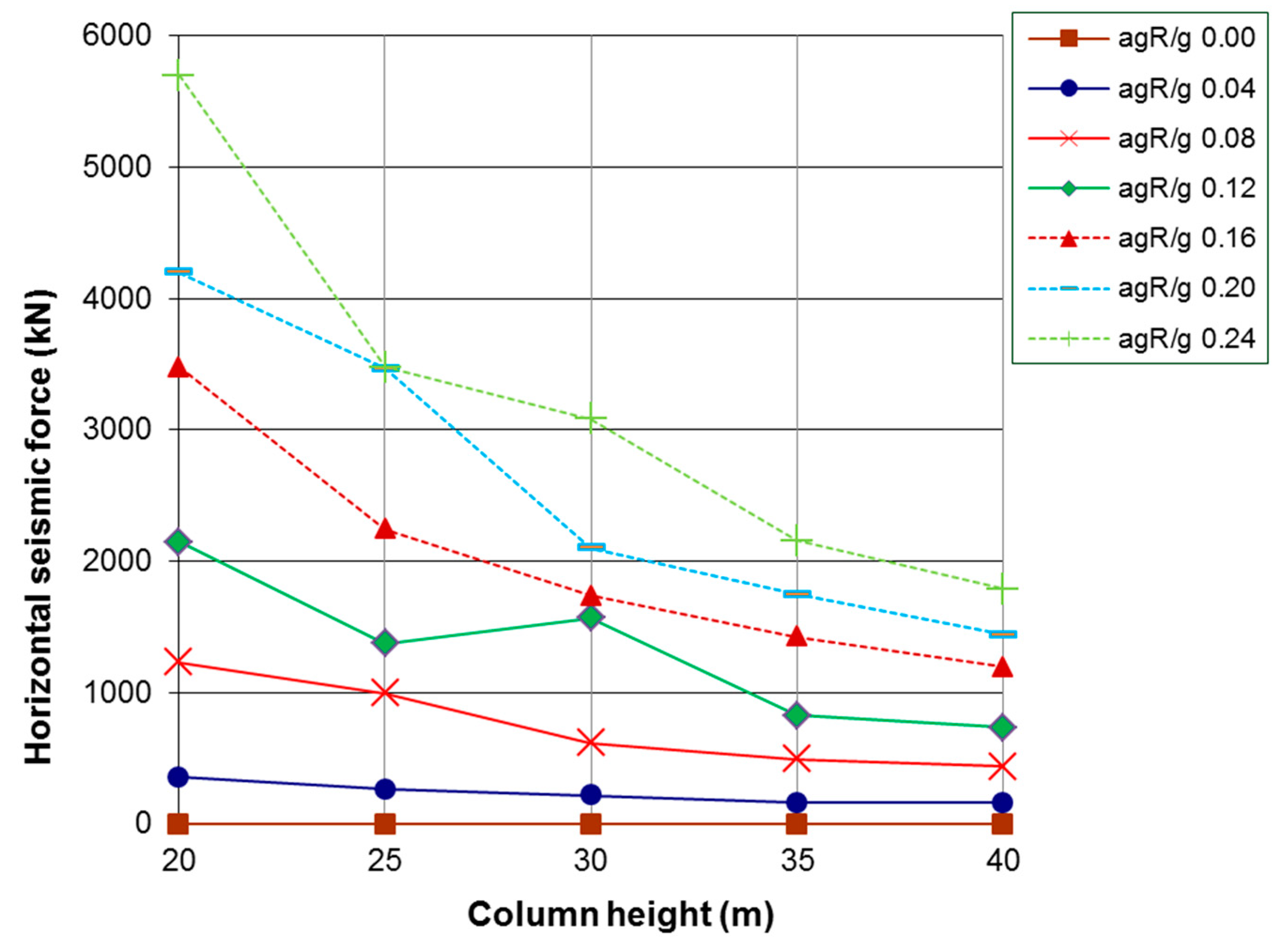
| Column Height (m) | agR/g | Euroc. 8 (kN) | Housner (kN) |
|---|---|---|---|
| 20 | 0.00 | 0.00 | 0.00 |
| 20 | 0.04 | 341.90 | 359.16 |
| 20 | 0.08 | 1232.35 | 1210.01 |
| 20 | 0.12 | 2144.68 | 2055.94 |
| 20 | 0.16 | 3479.77 | 3253.73 |
| 20 | 0.20 | 4198.74 | 3923.55 |
| 20 | 0.24 | 5702.18 | 5252.09 |
| 25 | 0.00 | 0.00 | 0.00 |
| 25 | 0.04 | 249.65 | 261.80 |
| 25 | 0.08 | 980.62 | 996.25 |
| 25 | 0.12 | 1344.01 | 1376.53 |
| 25 | 0.16 | 2245.38 | 2209.03 |
| 25 | 0.20 | 3468.79 | 3305.40 |
| 25 | 0.24 | 3477.36 | 3367.75 |
| 30 | 0.00 | 0.00 | 0.00 |
| 30 | 0.04 | 171.02 | 219.44 |
| 30 | 0.08 | 602.54 | 617.07 |
| 30 | 0.12 | 1568.58 | 1568.41 |
| 30 | 0.16 | 1694.09 | 1739.40 |
| 30 | 0.20 | 2049.89 | 2101.60 |
| 30 | 0.24 | 3082.29 | 3033.61 |
| 35 | 0.00 | 0.00 | 0.00 |
| 35 | 0.04 | 110.95 | 161.97 |
| 35 | 0.08 | 434.30 | 494.77 |
| 35 | 0.12 | 824.62 | 824.61 |
| 35 | 0.16 | 1356.35 | 1426.94 |
| 35 | 0.20 | 1661.61 | 1746.68 |
| 35 | 0.24 | 2063.15 | 2155.73 |
| 40 | 0.00 | 0.00 | 0.00 |
| 40 | 0.04 | 108.76 | 159.40 |
| 40 | 0.08 | 345.11 | 440.62 |
| 40 | 0.12 | 666.97 | 732.58 |
| 40 | 0.16 | 1153.28 | 1194.16 |
| 40 | 0.20 | 1390.90 | 1442.49 |
| 40 | 0.24 | 1707.13 | 1790.73 |
Publisher’s Note: MDPI stays neutral with regard to jurisdictional claims in published maps and institutional affiliations. |
© 2022 by the authors. Licensee MDPI, Basel, Switzerland. This article is an open access article distributed under the terms and conditions of the Creative Commons Attribution (CC BY) license (https://creativecommons.org/licenses/by/4.0/).
Share and Cite
Martínez-Martín, F.J.; Yepes, V.; González-Vidosa, F.; Hospitaler, A.; Alcalá, J. Optimization Design of RC Elevated Water Tanks under Seismic Loads. Appl. Sci. 2022, 12, 5635. https://doi.org/10.3390/app12115635
Martínez-Martín FJ, Yepes V, González-Vidosa F, Hospitaler A, Alcalá J. Optimization Design of RC Elevated Water Tanks under Seismic Loads. Applied Sciences. 2022; 12(11):5635. https://doi.org/10.3390/app12115635
Chicago/Turabian StyleMartínez-Martín, Francisco J., Víctor Yepes, Fernando González-Vidosa, Antonio Hospitaler, and Julián Alcalá. 2022. "Optimization Design of RC Elevated Water Tanks under Seismic Loads" Applied Sciences 12, no. 11: 5635. https://doi.org/10.3390/app12115635
APA StyleMartínez-Martín, F. J., Yepes, V., González-Vidosa, F., Hospitaler, A., & Alcalá, J. (2022). Optimization Design of RC Elevated Water Tanks under Seismic Loads. Applied Sciences, 12(11), 5635. https://doi.org/10.3390/app12115635