Article

An Improved Vector Control Strategy for Switched Reluctance Motor Drive Based on the Two-Degree-of-Freedom Internal Model Control

College of Marine Electrical Engineering, Dalian Maritime University, Dalian 116000, China
*
Author to whom correspondence should be addressed.
Appl. Sci. 2022, 12(11), 5407; https://doi.org/10.3390/app12115407
Submission received: 1 May 2022 / Revised: 24 May 2022 / Accepted: 24 May 2022 / Published: 26 May 2022
(This article belongs to the Section Energy Science and Technology)

Abstract

:
The unipolar sinusoidal current excited control strategy of the switched reluctance motor (SRM) has been widely attended for its wide driving area and acceptable torque ripple. However, due to the SRM’s time-varying, non-linear, and high coupling features, the traditional vector control strategies are unable to provide excellent current control performance. In this paper, a novel vector control method based on a two-degree-of-freedom internal model control (2DOF IMC) is proposed. The main objectives of this article are to improve the control precision and to enhance the system’s robustness. Firstly, considering the non-linear characteristics of the system in the rotating reference frame, a 2DOF IMC controller based on a simplified SRM model is designed and the stability analysis of the controller is implemented. Since the time-varying disturbance cannot be effectively eliminated using the 2DOF IMC with constant filter parameters, a simple adaptive disturbance observer (ADO) is incorporated into the inner-loop system to online estimate and eliminate these disturbances. Moreover, a stability analysis based on Lyapunov theory is also presented, and the ADO’s stability and convergence are guaranteed by tuning the adaption gain law. Finally, the effectiveness of the proposed control strategy is demonstrated by experiments, and the results illustrate that the proposed method can effectively improve the control and disturbance rejection performance of the SRM drives.

1. Introduction

Switched reluctance motors (SRMs) have received much attention due to the robust structure, large start-up torque, and high reliability under harsh environments, and have been employed in electric vehicles, wind power generation, the textile industry, etc. [1,2,3]. However, the torque ripple caused by the inherent structure and power supply mode limits its wide application in the industrial field [4,5].
Some advanced control strategies such as torque sharing functions (TSFs) [6,7], direct torque control (DTC) [8,9], direct instantaneous torque control (DITC) [10,11], and model predictive control (MPC) [12] are effective in reducing the torque ripple. In these strategies, improving the tracking accuracy of the controller is regarded as an effective method of suppressing the torque ripple [13]. However, during the implementation of these methods, there are still some problems that need to be overcome. On one hand, the precision torque model is difficult to obtain, which directly affects the performance of torque ripple suppression. On the other hand, these techniques need to simultaneously optimize the turn-on angle, turn-off angle, and chopping level, which undoubtedly increases the difficulties of the parameter tuning.
Different from these methods, unipolar current vector control (CVC) is a preferable scheme with satisfactory torque performance and can avoid complex torque model identification [14,15]. Such advantages are drawing increasing attention from the electric machinery community [16,17]. In [14], the current vector control strategy based on a hysteresis controller is applied in SRM to achieve the d q 0 -axes current regulation. On this basis, the maximum torque per ampere (MTPA) control scheme is adopted to further reduce negative torque. Similarly, in [15], the hysteresis controller is also adopted in the current loop based on the current vector control. The difference is that the hysteresis controllers are used to determine the voltage space vector applied in the next control period. In addition, to further suppress the torque ripple, a third harmonic current is injected into the reference zero-sequence current. The effectiveness of this method has been verified by experimental results. However, due to variable switching frequencies, the hysteresis controller leads to high electromagnetic interference and current ripple [5]. In [16], based on vector control, a conventional PI controller with a fixed switching frequency is used to track the reference current in the rotating reference frame. Moreover, in this method, the regulation range of the rotor speed is extended by using a space vector modulation (SVM) technology. Although a PI controller can provide a fixed switching frequency and zero steady-state error, it is still difficult to achieve a satisfactory control effect. The main reason is that there is a highly coupled relationship between different inputs of the SRM’s driver in the rotating reference frame. In addition, the disturbance suppression performance of the system cannot be guaranteed by using a conventional PI controller. In [17], considering the coupling relationship, an improved current regulation scheme is proposed, which consists of a PI, decoupling, and a feed-forward controller. According to the motor model in the rotating reference frame, the values of the transient and coupling terms are compensated in the control system to enhance the control performance. Despite the good tracking performance that can be obtained by using this method when the parameters of the model are accurate, thanks to the non-linear characteristic of the SRM caused by magnetic saturation and mutual inductance, the SRM is difficult to be precisely described by the analytical expression in the rotating reference frame.
As a controller with good robustness and no requirement for an accurate model, internal model control (IMC) has been widely applied to the motor driving system [18,19,20]. In [21], the IMC theory is used to design a current controller combining the support vector machine generalized inverse (SVMGI) for a permanent magnet synchronous motor (PMSM). Strong robustness and good dynamic performance are obtained. In [22], a novel decoupling control scheme consisting of an inverse system method and IMC is implemented on a PMSM. Compared with the conventional vector control scheme, the novel control method has better control accuracy and dynamic performance. In addition, the IMC is also applied in the induction motor driver system. In [23,24], based on the IMC, two improved current controllers for the vector control are designed to optimize the current control performance of induction motor drives. The experimental results verify the effectiveness of both control methods. Similarly, IMC is also an eligible candidate to handle the SRMs with the characteristics of non-linearity. However, for the conventional IMC, the set-point tracking and interference suppression performance is often unable to be simultaneously satisfied by adjusting a single filter parameter. For this reason, a two-degree-of-freedom internal model control (2DOF IMC) structure is proposed to deal with the aforementioned shortcoming, which can separate the set-point tracking response and external interference suppression characteristics of the system [25,26]. However, such good robustness cannot be guaranteed by the invariable filter parameter of 2DOF IMC for the SRM system. The reason is that the SRM system suffers from disturbance with time-varying characteristics, including model mismatch, parameter variation, and other unstructured dynamic uncertainties. Furthermore, different from other motors, the existence of the 0-axis current regulation increases the complexity of the controller design. Therefore, the 2DOF IMC controller used for the SRM system needs to be further developed to achieve a more accurate current regulation.
The purpose of this study is to develop a high-performance current control strategy for the SRM drive based on a 2DOF IMC strategy. The main contributions and features of this paper are summarized as follows:
(1)
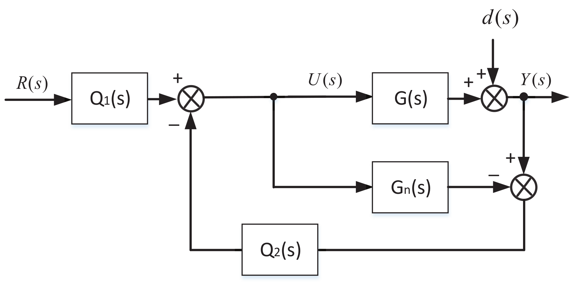
A novel 2DOF IMC controller is reported in this paper based on the SRM model in the rotating reference frame, which considers the coupling relationship between different axes. The proposed controller can provide good control performance by using only two adjustment parameters, and the good performance of the set-point tracking and disturbance rejection of the controller can be guaranteed simultaneously.
(2)
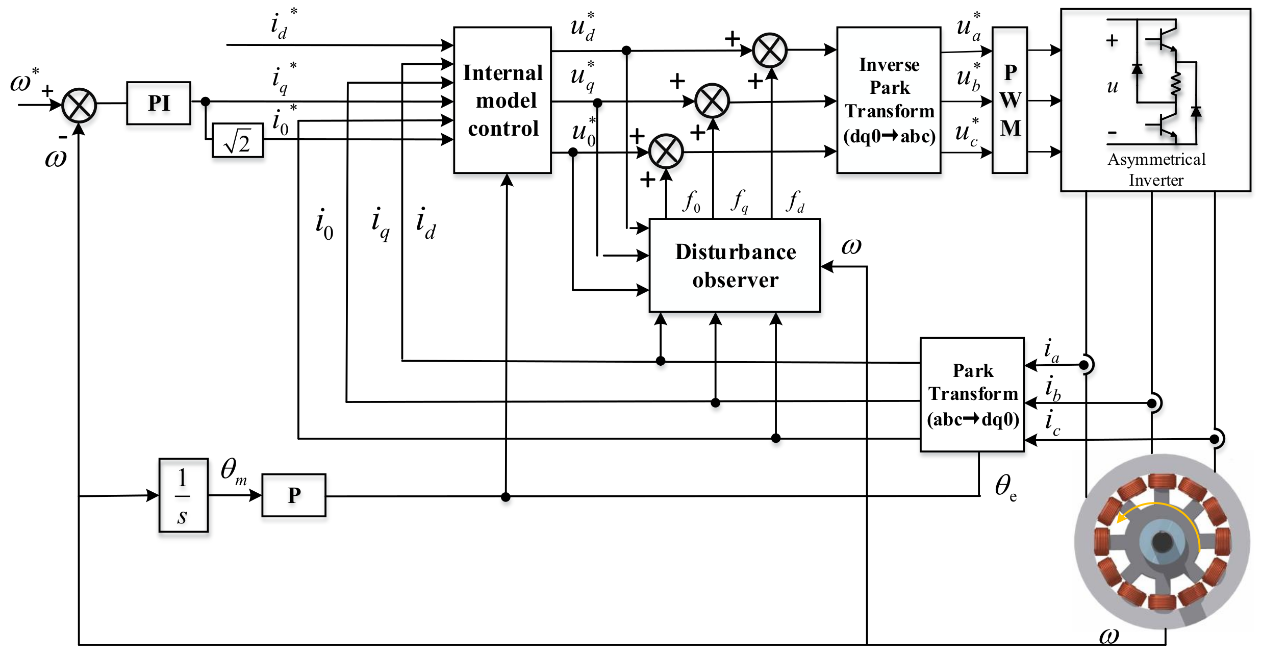
Secondly, an adaptive disturbance observer (ADO) is introduced to eliminate the time-variable disturbance. Furthermore, a stability analysis is carried out according to the Lyapunov theory, and a guideline in selecting the ADO gains is given.
(3)
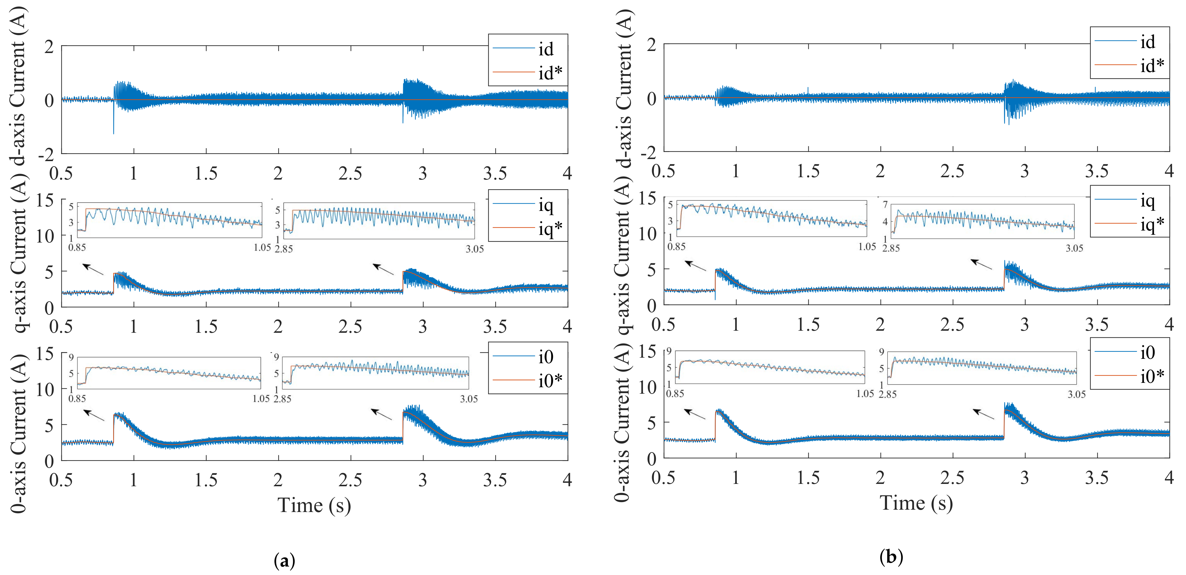
Finally, the experimental results demonstrate that the proposed control system can provide good tracking and disturbance rejection performance. On this basis, the torque ripple can be effectively suppressed by such good current control performance.
This paper is organized as follows. Section 1 introduces the SRM model in the three-phase and rotating reference frame. The control structure, design procedure, and ability analysis of the proposed 2DOF IMC controller are also described in Section 1. Section 2 illustrates the design procedure of the ADO and the stability analysis. Section 3 presents the experimental results. Section 4 concludes this paper.

2. 2DOF IMC for SRM

2.1. Mathematical Model of the SRM

Neglecting the magnetic saturation and mutual inductance, the self-inductance can be described by the Fourier series with DC and fundamental harmonic components:
L a = L d c + L a c cos θ e L b = L d c + L a c cos ( θ e 2 / 3 π ) L c = L d c + L a c cos ( θ e + 2 / 3 π )
where L a , L b and L c are the A-, B- and C-phase self-inductance; L d c and L a c are the coefficients of DC and fundamental harmonic component. The θ e is the electrical rotor position, and the relationship between θ e and mechanical angle θ m can be expressed as:
θ e = P θ m
where the P is the number of rotor poles.
The voltage balance equation of SRMs in the three-phase reference frame can be described as:
u a u b u c = R i a i b i c + p L a 0 0 0 L b 0 0 0 L c i a i b i c
where u a , u b and u c are A-, B- and C-phase voltage, i a , i b and i c are A-, B- and C-phase current, and R and p are the phase winding resistance and differential operator.
By using Park’s transformation, the model in the rotating reference frame can be further obtained, and it can be denoted as:
u d u q u 0 = R i d i q i 0 + ω e L a c sin 3 θ e L d c L a c cos 3 θ e 0 L d c L a c cos 3 θ e L a c sin 3 θ e 2 2 L a c 0 0 0 i d i q i 0 + L d c + 1 2 L a c cos 3 θ e 1 2 L a c sin 3 θ e 2 2 L a c 1 2 L a c sin 3 θ e L d c 1 2 L a c cos 3 θ e 0 2 2 L a c 0 L d c p i d i q i 0
where u d , u q and u 0 are the d-, q- and 0-axis voltage; i d , i q and i 0 are the d-, q- and 0-axis current. The ω e is the electrical rotor speed.
The instantaneous torque T e in the rotating reference frame is given as:
T e = 2 P 2 L a c i 0 i q P 4 L a c ( i d 2 + i q 2 ) sin ( 3 θ e + 2 β ) )
where the β is the advanced angle.
From (5), it is obvious the second term makes no contribution to the average torque, and it is generally treated as the torque ripple. Hence, in this paper, to reduce the ripple term, the i d = 0 strategy is adopted and the β = π 2 is selected. Then, the T e is simplified as:
T e = 2 P 2 L a c i 0 i q

2.2. Design of the 2DOF IMC Current Regulator

In this subsection, according to the characteristics of SRMs, a 2DOF IMC controller is designed. Then, the stability analysis and parameter tuning of the controller are given. Figure 1 depicts the block diagram of the 2DOF IMC based on vector control. The 2DOF internal model control is used for the current loop and the traditional PI controller is adopted for the speed loop.
In Figure 2, the structure of the 2DOF IMC is displayed. The 2DOF IMC can be regarded as a special feedback structure consisting of a set-point controller Q 1 ( s ) , disturbance rejection controller Q 2 ( s ) , plant G ( s ) and process model G n ( s ) . In the figure, the R ( s ) , U ( s ) , Y ( s ) , d ( s ) are the reference input, process output, system output and external interference signal, respectively. The input and output relationship of a 2DOF IMC can be described as:
Y ( s ) = R ( s ) G ( s ) Q 1 ( s ) + d ( s ) ( 1 Q 2 ( s ) G n ( s ) ) 1 + Q 2 ( s ) ( G ( s ) G n ( s ) )
If the corresponding process model G n ( s ) is perfect, i.e., G ( s ) = G n ( s ) , then
Y ( s ) = R ( s ) Q 1 ( s ) G n ( s ) + d ( s ) ( 1 Q 2 ( s ) G n ( s ) )
From (8), the set-point tracking and disturbance rejection are decoupled and independently adjusted by the Q 1 ( s ) , Q 2 ( s ) , respectively.
Based on the above assumptions, if Q 1 ( s ) = Q 2 ( s ) = G n 1 ( s ) can be realized, then Y ( s ) = R ( s ) can be obtained. It means that the system is characterized by strong robustness. However, in practical application, this is difficult to achieve. Hence, in this paper, the controllers Q 1 ( s ) and Q 2 ( s ) are supplemented with low-pass filters f 1 ( s ) , f 2 ( s ) , which can be further expressed as:
Q 1 ( s ) = G n 1 ( s ) f 1 ( s ) Q 2 ( s ) = G n 1 ( s ) f 2 ( s )
where the f 1 ( s ) and f 2 ( s ) are designed as:
f 1 ( s ) = 1 1 + λ 1 s f 2 ( s ) = 1 1 + λ 2 s
where the filter parameters λ 1 and λ 2 should satisfy λ 1 > 0 and λ 2 > 0 , respectively.
By simplifying the structure in Figure 2, the 2DOF IMC can be equivalent to the traditional feedback structure, shown in Figure 3, and the corresponding IMC controllers T ( s ) and F ( s ) can be developed as:
T ( s ) = Q 1 ( s ) Q 2 ( s ) = 1 + λ 2 s 1 + λ 1 s F ( s ) = Q 2 1 Q 2 G n ( s )
Based on the above design process, a 2DOF IMC controller for the SRM is constructed. To simplify the design of the controller, the average model is chosen as process model G n , as illustrated in the following equation.
u d u q u 0 = R i d i q i 0 + ω e 0 L d c 0 L d c 0 2 2 L a c 0 0 0 i d i q i 0 + L d c 0 2 2 L a c 0 L d c 0 2 2 L a c 0 L d c p i d i q i 0
For the current loop system, the SRM can be described as a three-input and three-output system. According to (12) and using the Laplace transform, the system can be equivalent to:
Y ( s ) = G ( s ) U ( s )
where:
U ( s ) = u d ( s ) u q ( s ) u 0 ( s ) T Y ( s ) = i d ( s ) i q ( s ) i 0 ( s ) T G n ( s ) = R + L d c s L d c ω e 2 2 L a c s L d c ω e R + L d c s 2 2 L a c ω e 2 2 L a c s 0 R + L d c s 1 .
Substituting (13) into (11), the controllers T ( s ) and F ( s ) for the SRM system can be deduced.
T ( s ) = Q 1 ( s ) Q 2 ( s ) = 1 + λ 2 s 1 + λ 1 s F ( s ) = 1 λ 2 R s + L d c L d c ω e s 2 2 L a c L d c ω e s R s + L d s 2 L a c ω e 2 s 2 2 L a c 0 R s + L d c

2.3. Stability Analysis and Parameter Tuning

For the closed-loop system, the necessary and sufficient condition for stabilization is:
| F ( j ω ) G n ( j ω ) | l ¯ m ( j w ) < 1 ω
where l ¯ m ( j ω ) is the upper limit of the model error and F ( j ω ) G ( j ω ) = 1 λ 2 ( j ω ) . Then,
l ¯ m ( j ω ) < λ 2 ( j ω ) ω
For a certain modeling error upper bound l ¯ m , if the inequality condition (17) can be satisfied [23], the stability of the system can be guaranteed. Furthermore, the larger λ 2 , the greater the allowed range of error between the model and process model. As a result, the selection of the parameter λ 2 not only determines system stability but also affects the control performance.
According to (15), the set-point tracking of the 2DOF IMC is affected by λ 1 and λ 2 , while only λ 2 determines disturbance rejection. As a result, in this paper, the λ 2 is adjusted firstly, and then the λ 1 is determined.
With reference to [25], the λ 2 is set to be less than λ 1 , and the relationship of both parameters is given:
λ 2 = γ λ 1
where 0 γ 1 , and then the controller T ( s ) can be written as:
T ( s ) = 1 + γ λ 1 1 + λ 1
It should be noted that, on the one hand, due to adopting an average model, the uncertainties of the model with rotor position are neglected in the 2DOF IMC controller. On the other hand, the parameter variations, inductance harmonics, and other uncertainties caused by the magnetic saturation are also not considered. These time-variable uncertainties can not be perfectly eliminated by constant filter parameters, which will affect the control performance. Hence, a disturbance observer controller is introduced to estimate and eliminate these uncertainties in real time.

3. 2DOF IMC Strategy for SRMs Based on ADO

In this section, based on the average model of SRMs (in (13)), a simple ADO is constructed. Using the ADO, the disturbances are predicted based on the steepest descent technique and compensate the 2DOF IMC controller in the next control period. Then, the stability analysis of the ADO is implemented based on Lyapunov theory, and on the basis of this, a selection guideline for the ADO parameter is provided.
Figure 4 shows the structure diagram of the 2DOF IMC ADO scheme based on vector control. It can be seen that the ADO is incorporated into the current loop and used to estimate the disturbance.

3.1. Design of the ADO

Considering the parameter variation and unknown uncertainties, the system model can be further described by the following equation based on (13).
u d u q u 0 = R i d i q i 0 + ω e 0 L d c 0 L d c 0 2 2 L a c 0 0 0 i d i q i 0 + L d c 0 2 2 L a c 0 L d c 0 2 2 L a c 0 L d c p ( i d i q i 0 ) + f d f q f 0
where the disturbances f d , f q and f 0 are given by:
f d = Δ R + Δ L d c p ( i d ) + Δ L a c p ( i 0 ) + ϵ d f q = Δ R + Δ L a c ω e i 0 + Δ L d c p ( i q ) + ϵ q f 0 = Δ R + 1 2 Δ L a c i 0 + 1 2 Δ L a c p ( i d ) + Δ L d c p ( i 0 ) + ϵ 0
In this equation, the Δ R , Δ L a c and Δ L d c represent the uncertainties of R, L a c and L d c . ϵ d , ϵ q , ϵ 0 are the d-, q- and 0-axis uncertainties caused by the unmodeled dynamics.
Based on (20), an ADO is designed to estimate the uncertain disturbances f d , f q , f 0 . Firstly, the discrete-time state-space model of ADO is given:
x ( k + 1 ) = A x ( k ) + B ( u ( k ) f ( k ) )
where:
x ( k ) = i d ( k ) i q ( k ) i 0 ( k ) T u ( k ) = u d ( k ) u q ( k ) u 0 ( k ) T f ( k ) = f d ( k ) f q ( k ) f 0 ( k ) T A = 1 2 L d c R T s 2 L d c 2 L a c 2 2 L d c 2 T s ω e 2 L d c 2 L a c 2 2 L a c R T s ω e 2 L d c 2 L a c 2 T s ω e 1 R T s L d c L a c T s ω e L d c L a c R T s 2 L d c 2 L a c 2 L d c L a c T s ω e 2 L d c 2 L a c 2 1 2 L d c R T s 2 L d c 2 L a c 2 B = 2 L d c T s 2 L d c 2 L a c 2 0 2 L a c T s 2 L d c 2 L a c 2 0 T s L d c 0 L a c T s 2 L d c 2 L a c 2 0 2 L d c T s 2 L d c 2 L a c 2
where k is kth instant and T s is the control period. Based on (22), the adaption observer can be designed as:
x ^ ( k + 1 ) = A x ^ ( k ) + B ( u ( k ) f ^ ( k ) )
where the x ^ , f ^ are the observed values of x , f . The errors e between the actual and observer values of the state variable x can be defined as:
e ( k ) = e d ( k ) e q ( k ) e 0 ( k ) = i d ( k ) i ^ d ( k ) i q ( k ) i ^ q ( k ) i 0 ( k ) i ^ 0 ( k )
Moreover, a quadratic error function E ( k ) = 1 2 e 2 ( k ) is used to assess the performance of ADO. Hence, in this paper, to minimize the E ( k ) , the steepest descent method is adopted [27], and the Jacobian matrix J can be given as:
J = E ( k ) f ^ ( k ) = B e ( k )
Then, the estimated value at the next control period can be obtained:
f ^ ( k + 1 ) = f ^ ( k ) + f ^ ( k ) = f ^ ( k ) μ B e ( k )
where μ is the adaption gain, and f ^ = f ^ ( k ) f ^ ( k 1 ) . As the SRM system has a natural dynamic characteristic of bounded-input bounded-output stability, the output f ^ ( k ) of ADO should also be bounded within certain limits.

3.2. Stability Analysis and Parameter Tuning for the ADO

To guarantee the stability of the proposed ADO, a discrete-time Lyapunov function is selected as:
V ( k ) = 1 2 e ( k ) e ( k ) T
According to the Lyapunov convergence criterion, if the following condition (28) is satisfied, the observed system is Lyapunov-stable.
V ( k ) V ( k ) < 0
where:
V ( k ) = V ( k + 1 ) V ( k ) = 1 2 ( e ( k + 1 ) T e ( k + 1 ) e ( k ) T e ( k ) )
Since V ( k ) > 0 , the V ( k ) < 0 should be satisfied. Assuming that the observed disturbance is naturally continuous, with a bandwidth significantly less than the observation period, the change value e ( k ) can be calculated by combining (22) and (23) with the adaptation law in (26).
e ( k ) = e ( k + 1 ) e ( k ) = μ B B T e ( k )
Substituting (30) into (29), the following equation can be deduced:
V ( k ) = 1 2 e ( k ) T μ B B T ( 2 I 3 × 3 μ B B T ) e ( k )
where I 3 × 3 is a unit matrix. As the μ is a positive value, the ( 2 I 3 × 3 μ B B T ) should be a positive definite matrix. Therefore, by combining (22), the range of the μ can be obtained, as shown in (32).
0 < μ < 2 L d c 2 + L a c 2 + 2 L a c L d c T s 2
As a consequence, the suggested observer’s stability may be ensured when μ matches the criterion in (32).

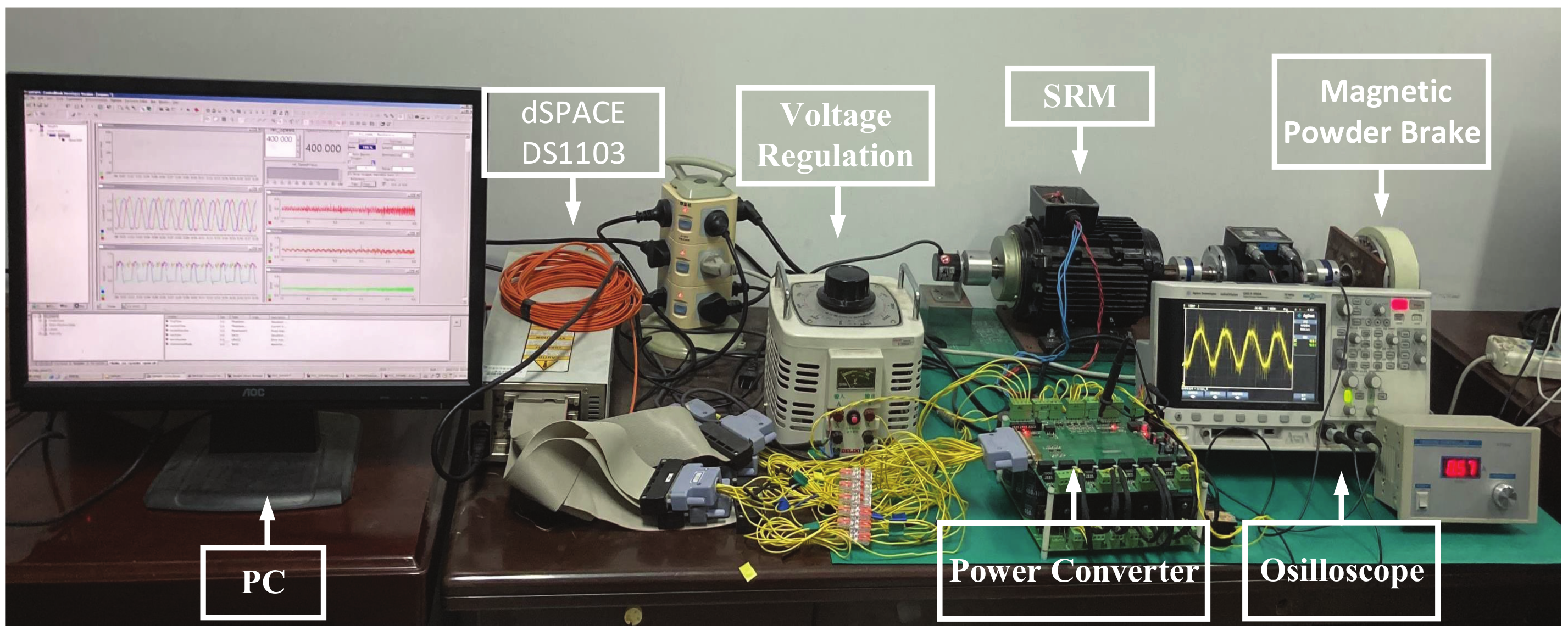
4. Experimental Verification

To verify the effectiveness of the proposed method, comparative experiments of the method in [14] and the proposed 2DOF IMC ADO scheme are carried out by using an SRM platform. The platform is shown in Figure 5, consisting of an SRM, a power converter, a dSPACE DS-1103 controller board, an oscilloscope, etc. The detailed parameters of the test 1.5 kW 3-phase 12/8 SRM are listed in Table 1. The dSPACE DS-1103 controller board is employed to execute both control schemes. The asymmetric half-bridge converter is adopted to drive the SRM, and the PWM frequency is 10 kHz. A magnetic powder brake is coupled to the shaft of the SRM to simulate the load torque. The Hall effect sensors and incremental encoder are used to measure the phase current and rotor position, respectively. The parameters are used in the SRM driver as follows: L d c = 0.075 H , L a c = 0.069 H , R = 0.9 Ω , P = 8 , λ 2 = 0.003 , γ = 0.7 .

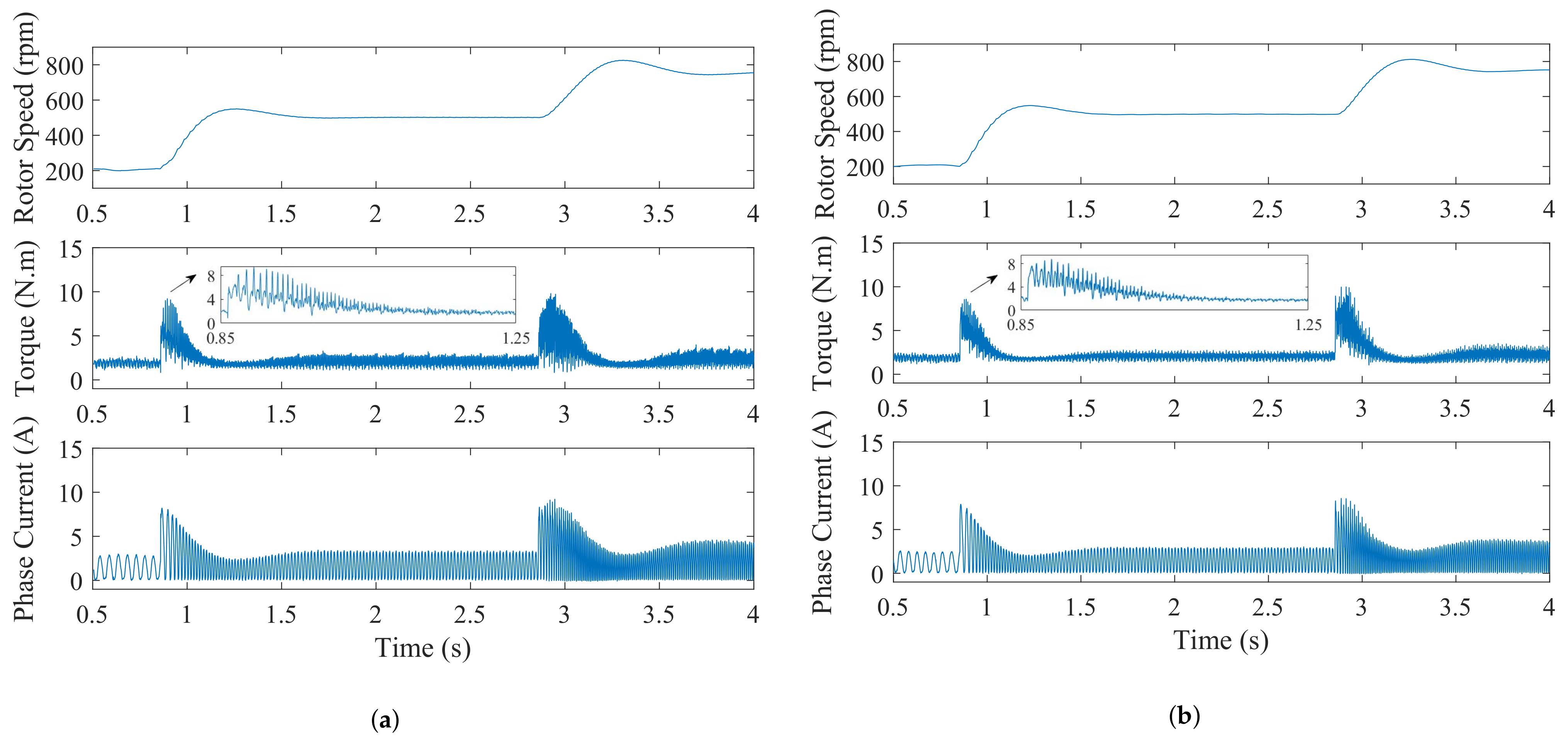
4.1. Experimental Results with Rotor Speed Change

The experimental results of the approach in [14] and the proposed 2DOF IMC ADO method under a 2 N · m load are presented, where the rotor speed step commands are 200 r/min, 500 r/min and 750 r/min, respectively. Figure 6 shows the comparative results of the d q 0 -axes currents, and Figure 7 shows the measured rotor speed, total torque and A-phase current of the two methods, where i d * , i q * , i 0 * are the reference current of i d , i q , i 0 .
When the reference rotor speed steps from 200 rpm to 500 rpm at 0.86 s, the regulation time of Nakao’s method is 0.4 s (d-axis), 0.1s (q-axis) and 0.02 s (0-axis), respectively, as shown in Figure 6a. However, it is improved to 0.2 s (d-axis), 0.06 s (q-axis) and 0.01 s (0-axis) by using the proposed method, as shown in Figure 6b. When the reference rotor speed steps from 500 rpm to 750 rpm at 2.86 s, compared with Nakao’s method, the same conclusion can be drawn that the proposed 2DOF IMC ADO method has a better dynamic response speed.
In addition, it can also be observed from Figure 6 that, with the increase in the reference rotor speed, the d-axis current fluctuation becomes large. For the method in [14], the maximum overshoot and fluctuation of the d-axis current are up to 1.4 A and 1.6 A, respectively. By contrast, the smaller maximum overshoot and fluctuation of the d-axis current based on the proposed method can be observed in Figure 6b, which is only 1 A and 1.5 A. Furthermore, under the steady-state condition, it is clear that the 2DOF IMC ADO scheme results in an improvement in tracking the performance of the d q 0 -axes current (Figure 6). This is because the SRM’s non-linearity and coupling characteristic between different axes can be fully considered in the proposed 2DOF IMC ADO method. Additionally, the introduction of the SRM model can also provide a quick response capability for the proposed method, which is not commonly found in the method in [14]. Due to the quick current response and good tracking capability of the proposed method, better torque ripple minimization performance can be also seen in Figure 7. As Figure 7 reveals, when the command speed changes at 0.86 s, the T e regulation time of Nakao’s method is 0.3 s, and a large torque ripple up to 8.5 N · m can be observed. However, under the same parameters of the speed-loop controller, the torque regulation time of the proposed method is only 0.2 s, and the torque ripple is reduced. After 2.85 s, the output torque has a shorter regulation time than the method in [14], and the good torque ripple suppressed performance is presented in Figure 7b.
To further evaluate the torque ripple, a quantitative analysis is applied by introducing the percentages of the torque ripple T r . The T r can be obtained by:
T r = T m a x T m i n T a v g × 100 %
where the T m a x , T m i n , T a v g are the maximum value, minimal value and average value of total torque in one electric angle period. The torque ripple percentages T r of both methods are summarized in Table 2.
The T r findings in Table 2 show that, compared with the technique in [14], the torque ripple percentages of the suggested method are lower, decreasing by 4.9%, 10.35% and 6.7%, respectively. The results indicate that better d q 0 -axes current tracking performance brings a smoother output torque, which is consistent with (6). Based on the experimental results and analysis above, it can be found that, by using the proposed method, the dynamic and steady-state performance of the d q 0 -axes current controllers are improved at the different operating speeds. In addition, the 2DOF IMC ADO scheme provides an improvement in torque ripple reduction for the SRM system.

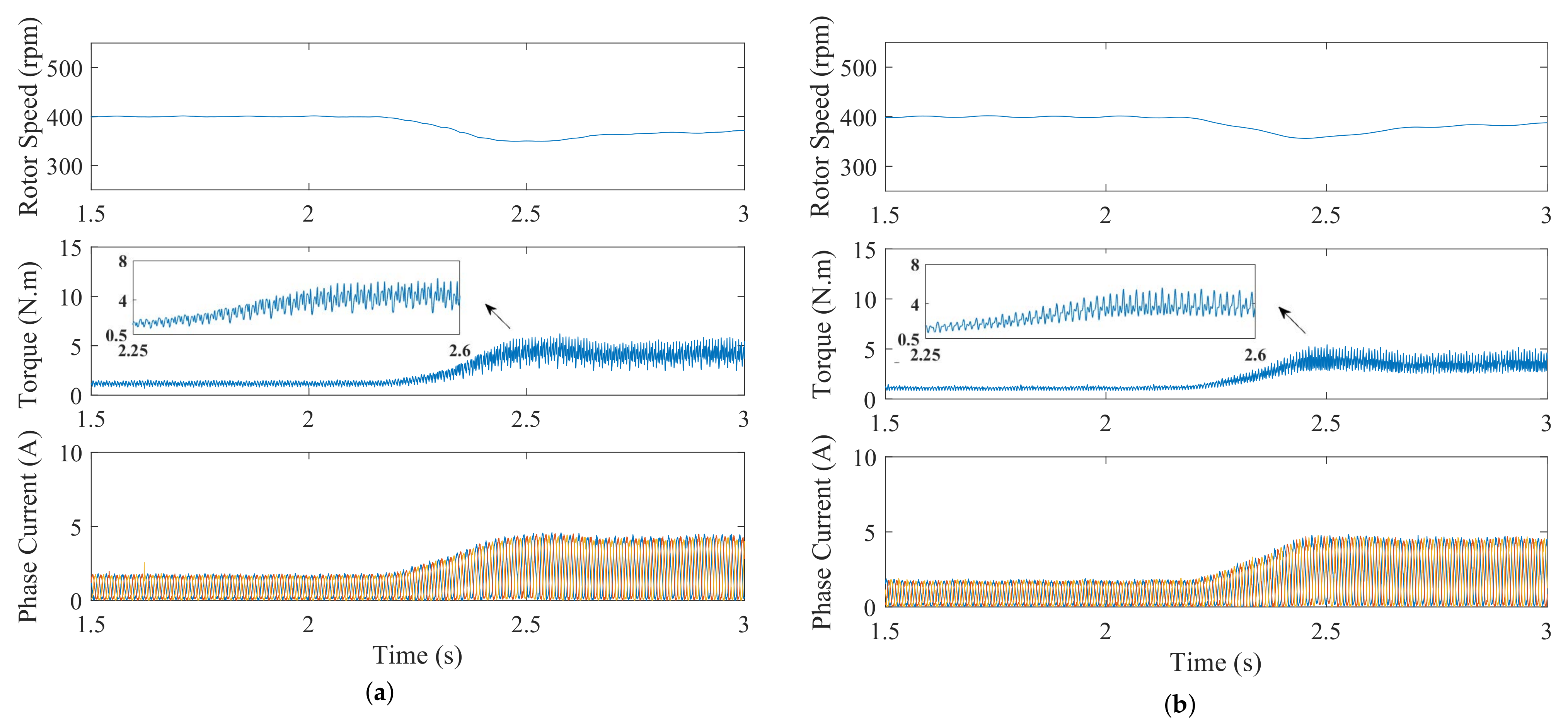
4.2. The Experimental Result with Load Torque Change

Figure 8 and Figure 9 illustrate the experimental results for the method in [14] and the 2DOF IMC ADO method when the SRM operates at 400 r/min with 1 N · m load. When the time is 2.3 s, the load torque varies from 1 N·m to 4 N·m. Figure 8 displays the experimental results of d q 0 -axes currents, where i d * , i q * , i 0 * are the reference current of i d , i q , i 0 . Figure 9 shows the experimental results of the rotor speed, total torque and phase current.
It can be seen from Figure 8b that the d-axis current fluctuations of both methods increase when the load torque changes at 2.3 s. The method in [14] results in a i d fluctuation of 1.25 A; in contrast, it is only 0.93 A in the case of the 2DOF IMC ADO method. Moreover, compared to Figure 8a,b, it is obvious that a significant improvement is obtained in the current tracking performance by using the proposed 2DOF IMC ADO method. Similar to the above analysis, by considering the SRM characteristics, the proposed method can achieve good control performance and a fast response under a step-torque load case, as shown in Figure 9. In addition, as the ADO can eliminate the disturbance from the variable load torque, the robustness is further enhanced, which can be observed in Figure 8 and Figure 9. With the good current control performance, good torque ripple suppression can be achieved by using the proposed method in Figure 9. Furthermore, it can be seen that when the load torque steps, a shorter regulation time and smaller ripple of the proposed method can be found, as in Figure 9, which is also consistent with the above analysis.
Table 3 lists the results of the T r for both methods. Obviously, in terms of torque ripple suppression, the proposed 2DOF IMC ADO approach outperforms the method in [14], and the T r is reduced by 8.25% and 18%. The above-compared results indicate that the proposed method can achieve good tracking and disturbance rejection performance at a step load torque condition.

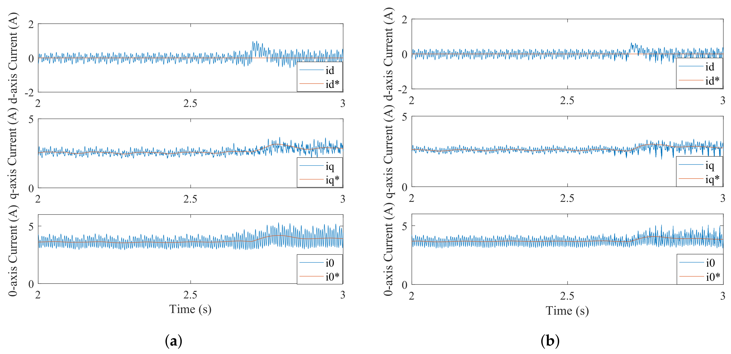
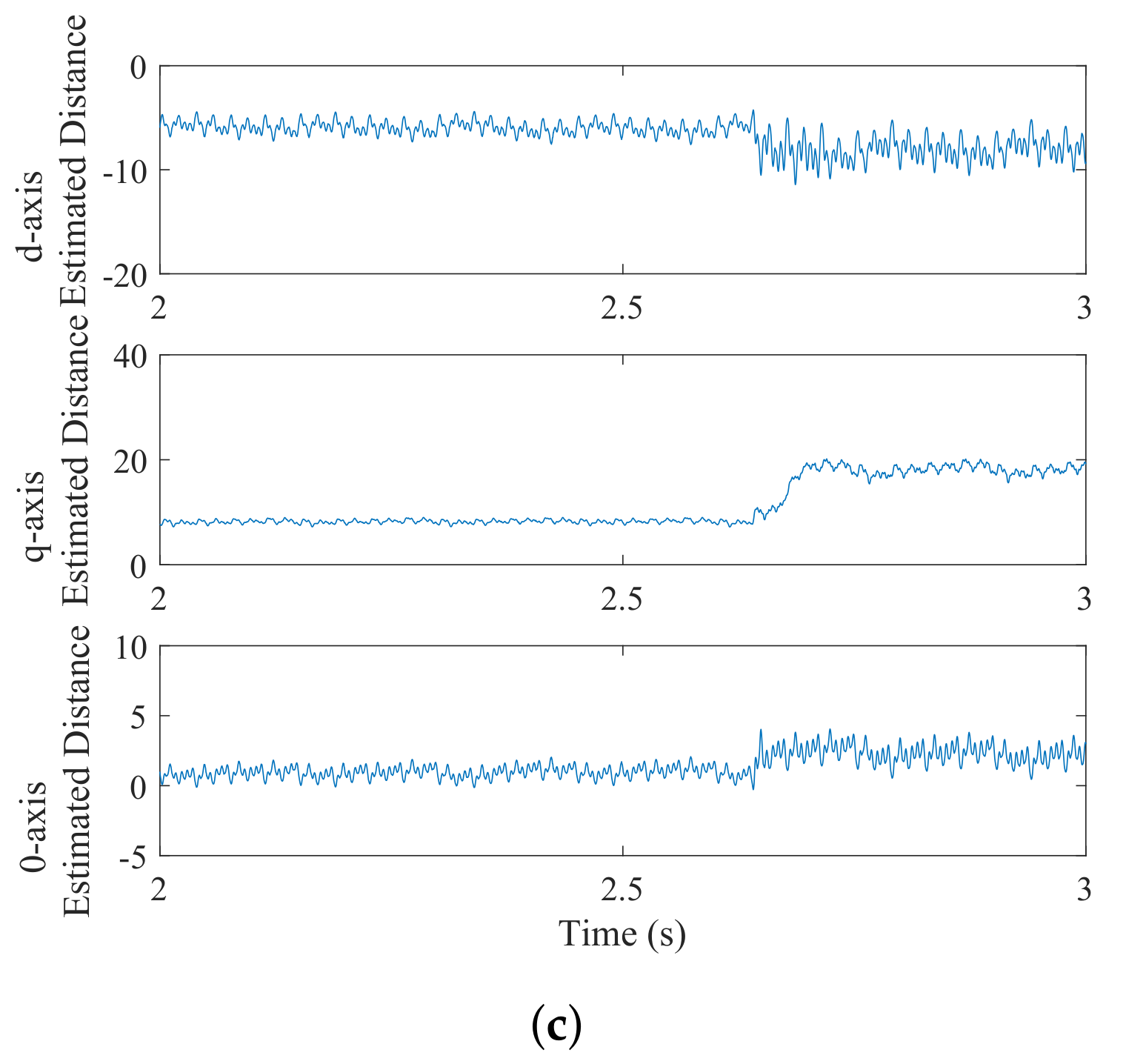
4.3. Experimental Results with Parameter Variation

The experimental results of the 2DOF IMC method and 2DOF IMC ADO method are given at 400 r/min and 3 N · m under the inductance mismatch. Figure 10a,b shows the d q 0 a x e s currents experimental results of both methods, where i d * , i q * , i 0 * are the reference current of i d , i q , i 0 . When the time is 2.7 s, the values of L d c and L a c are changed to 0.5 times the initial values. It can be seen from Figure 10a,b that after 2.7 s, due to the inaccurate inductance parameters, the d q 0 -axes current fluctuations of both methods begin to increase in varying degrees, which are the natural result of the poor relative stability under parameter variation. It is noted that when the inductance parameters start to vary at 2.7 s, the overshoot of the d-axis current based on both methods is 1.05 A and 0.64 A, respectively. In addition, the regulation time of the method in [14] is 0.105 s (d-axis), 0.12 s (q-axis) and 0.15 s (0-axis). By contrast, the d q 0 -axes current of the 2DOF IMC ADO method can achieve the steady state in 0.08 s, 0.11 s and 0.146 s, respectively. Additionally, the d q 0 -axes current fluctuations of the proposed method are smaller than that of the 2DOF IMC method in most instances. The reason is that the disturbances caused by parameter mismatch are quickly modified by the proposed ADO. The compensation of the ADO not only guarantees good current tracking performance but also enhances the system’s disturbance rejection capabilities (Figure 10). The curves of the estimated disturbance voltages are given in Figure 10c. Although the ADO is also affected by the parameter mismatch, the ADO can quickly converge to real values.
Based on the experimental results and analysis, it can be confirmed that by combining the ADO, the 2DOF IMC ADO method can effectively estimate the disturbance caused by parameter mismatches to achieve good current control performance and strong robustness.

5. Conclusions

This paper reports on a novel 2DOF IMC strategy of unipolar current excited vector control applied to the SRM driver. A 2DOF IMC controller has been realized to improve the tracking performance of the current controller. Then, to solve the problem whereby the 2DOF IMC cannot deal with the time-varying disturbance, an ADO is embedded in the control system. In addition, the adaptive gain μ of the ADO is tuned to ensure the stability and convergence of the system. The effectiveness and feasibility are verified by contrast experiments.
The main features and advantages of the proposed scheme can be summarized as follows:
(1)
The 2DOF IMC ADO can effectively reduce the current tracking errors and quickly converge to stable conditions when the system is affected by different disturbances.
(2)
With the improvement in the control precision for the current controller, the proposed 2DOF IMC ADO scheme also delivers good performance in torque ripple suppression.
(3)
The regulation performance of the 2DOF IMC ADO controller can be guaranteed even with inaccurate model parameters.

Author Contributions

Conceptualization, D.L. and G.W.; methodology, D.L.; software, D.L. and J.L.; validation, D.L. and J.L.; formal analysis, D.L. and J.L.; investigation, J.L.; resources, Y.F.; data curation, J.L.; writing—original draft preparation, D.L.; writing—review and editing, J.L. and G.W.; visualization, Y.F.; supervision, D.M.; project administration, G.W.; funding acquisition, D.M. All authors have read and agreed to the published version of the manuscript.

Funding

This work was funded by the Fundamental Research Funds for the Central Universities under Grant 3132021106.

Data Availability Statement

Not applicable.

Conflicts of Interest

The authors declare no conflict of interest.

References

  1. Lawrenson, P. Switched-reluctance motor drives. IEEE Rev. 1983, 29, 144–147. [Google Scholar] [CrossRef]
  2. Chen, H.; Liu, C.; Chen, Z. Simulation and implementation of wind turbine based on switched reluctance motor drive. In Proceedings of the 2012 3rd IEEE International Symposium on Power Electronics for Distributed Generation Systems (PEDG), Aalborg, Denmark, 25–28 June 2012. [Google Scholar]
  3. Valdivia, V.; Todd, R.; Bryan, F.J.; Barrado, A. Behavioral modeling of a switched reluctance generator for aircraft power systems. IEEE Trans. Ind. Electron. 2014, 61, 2690–2699. [Google Scholar] [CrossRef]
  4. Liu, J.; Wang, G.; Sun, L.; Liu, D.; Fan, Y. A Novel Method to Obtain the Flux-Linkage Characteristics of Switched Reluctance Motors. IEEE Trans. Magn. 2021, 57, 8205011. [Google Scholar] [CrossRef]
  5. Valenciagarcia, D.F.; Tarvirdilu-Asl, R.; Garcia, C.; Rodriguez, J.; Emadi, A. A review of predictive control techniques for switched reluctance machine drives. Part I: Fundamentals and current control. IEEE Trans. Energy Convers. 2020, 36, 1313–1322. [Google Scholar]
  6. Ye, J.; Bilgin, B.; Emadi, A. An offline torque sharing function for torque ripple reduction in switched reluctance motor drives. IEEE Trans. Energy Convers. 2015, 30, 726–735. [Google Scholar] [CrossRef]
  7. Xia, Z.; Bilgin, B.; Nalakath, S.; Emadi, A. A new torque sharing function method for switched reluctance machines with lower current tracking error. IEEE Trans. Ind. Electron. 2020, 68, 10612–10622. [Google Scholar] [CrossRef]
  8. Sun, X.; Diao, K.; Yang, Z.; Lei, G.; Zhu, J. Direct torque control based on a fast modeling method for a segmented-rotor switched reluctance motor in hev application. IEEE J. Emerg. Sel. Top. Power Electron. 2021, 9, 232–241. [Google Scholar] [CrossRef]
  9. Ning, Y.; Xin, C.; Deng, Z.Q. Direct torque control for switched reluctance motor to obtain high torque-ampere ratio. IEEE Trans. Ind. Electron. 2018, 66, 5144–5152. [Google Scholar]
  10. Wang, S.; Hu, Z.; Cui, X. Research on novel direct instantaneous torque control strategy for switched reluctance motor. IEEE Access 2020, 66910–66916. [Google Scholar] [CrossRef]
  11. Sun, X.; Feng, L.; Diao, K.; Yang, Z. An Improved Direct Instantaneous Torque Control Based on Adaptive Terminal Sliding Mode for a Segmented-Rotor SRM. IEEE Trans. Ind. Electron. 2020, 68, 10569–10579. [Google Scholar] [CrossRef]
  12. Li, X.; Shamsi, P. Model Predictive Current Control of Switched Reluctance Motors With Inductance Auto-Calibration. IEEE Trans. Ind. Electron. 2016, 3934–3941. [Google Scholar] [CrossRef]
  13. Mademlis, C.; Kioskeridis, I. Gain-Scheduling Regulator for High-Performance Position Control of Switched Reluctance Motor Drives. IEEE Trans. Ind. Electron. 2010, 57, 2922–2931. [Google Scholar] [CrossRef]
  14. Nakao, N.; Akatsu, K. Vector control specialized for switched reluctance motor drives. IEEJ Trans. Ind. Appl. 2015, 194, 24–36. [Google Scholar]
  15. Kuai, S.; Zhang, H.; Xi, X.; Li, K. Unipolar sinusoidal excited switched reluctance motor control based on voltage space vector. IET Electr. Power Appl. 2019, 13, 670–675. [Google Scholar] [CrossRef]
  16. Zhu, Z.Q.; Lee, B.; Xu, L. Integrated field and armature current control strategy for variable flux reluctance machine using open winding. In Proceedings of the 2015 Tenth International Conference on Ecological Vehicles and Renewable Energies (EVER), Monte Carlo, Monaco, 31 March–2 April 2015. [Google Scholar]
  17. Nakao, N.; Kan, A. Vector control for switched reluctance motor drives using an improved current controller. In Proceedings of the 2014 IEEE Energy Conversion Congress and Exposition (ECCE), Pittsburgh, PA, USA, 14–18 September 2014; pp. 1379–1386. [Google Scholar]
  18. Saxena, S.; Hote, Y. Advances in Internal Model Control Technique: A Review and Future Prospects. IETE Tech. Rev. 2012, 29, 461–472. [Google Scholar] [CrossRef]
  19. Li, P.; Zhu, G.; Zhang, M. Linear active disturbance rejection control for servo motor systems with input delay via internal model control rules. IEEE Trans. Ind. Electron. 2021, 68, 1077–1086. [Google Scholar] [CrossRef]
  20. Sun, X.; Long, C.; Jiang, H.; Yang, Z.; Chen, J.; Zhang, W. High-performance control for a bearingless permanent-magnet synchronous motor using neural network inverse scheme plus internal model controllers. IEEE Trans. Ind. Electron. 2016, 63, 3479–3488. [Google Scholar] [CrossRef]
  21. Liu, G.; Chen, L.; Zhao, W.; Jiang, Y.; Qu, L. Internal model control of permanent magnet synchronous motor using support vector machine generalized inverse. IEEE Trans. Ind. Inform. 2013, 9, 890–898. [Google Scholar] [CrossRef]
  22. Sun, X.; Zhou, S.; Long, C.; Yang, Z. Internal model control for a bearingless permanent magnet synchronous motor based on inverse system method. IEEE Trans. Energy Convers. 2016, 31, 1539–1548. [Google Scholar] [CrossRef]
  23. Zhu, Q.; Yin, Z.; Zhang, Y.; Niu, J.; Li, Y.; Zhong, Y. Research on two-degree-of-freedom internal model control strategy for induction motor based on immune algorithm. IEEE Trans. Ind. Electron. 2015, 63, 1981–1992. [Google Scholar] [CrossRef]
  24. Yin, Z.; Bai, C.; Du, N.; Du, C.; Liu, J. Research on internal model control of induction motors based on luenberger disturbance observer. IEEE Trans. Power Electron. 2021, 36, 8155–8170. [Google Scholar] [CrossRef]
  25. Wu, S.; Li, Z.; Zhang, R. An improved 2-degree-of-freedom internal model proportional–integral–derivative controller design for stable time-delay processes. Meas. Control. 2020, 53, 841–849. [Google Scholar] [CrossRef] [Green Version]
  26. Juwari; Chin, S.Y.; Samad, N.; Aziz, B. Two-degree-of-freedom internal model control for parallel cascade scheme. In Proceedings of the 2008 International Symposium on Information Technology, Kuala Lumpur, Malaysia, 26–28 August 2008. [Google Scholar]
  27. Xu, H.; Zhang, Q. Comparison of convergence of the modified and relaxed hybrid steepest-descent methods for variational inequalities under different conditions. In Proceedings of the Third International Joint Conference on Computational Science Optimization, Huangshan, China, 28–31 May 2010. [Google Scholar]
Figure 1. Structure diagram of SRM control system based on the 2DOF IMC.
Applsci 12 05407 g001
Figure 2. Principle block diagram of the 2DOF IMC.
Applsci 12 05407 g002
Figure 3. Simplified block diagram of the 2DOF-IMC.
Applsci 12 05407 g003
Figure 4. The structure diagram of the 2DOF IMC ADO scheme.
Applsci 12 05407 g004
Figure 5. Experimental platform.
Applsci 12 05407 g005
Figure 6. Experimental results of the d q 0 -axes current when the speed changes. (a) Method in [14]. (b) 2DOF IMC ADO method.
Applsci 12 05407 g006
Figure 7. Experimental results of the rotor speed, total torque and phase current when the speed changes. (a) Method in [14]. (b) 2DOF IMC ADO method.
Applsci 12 05407 g007
Figure 8. Experimental results of the d q 0 -axes currents with the load torque change. (a) Method in [14]. (b) 2 DOF IMC ADO method.
Applsci 12 05407 g008
Figure 9. Experimental results of the rotor speed, total torque and phase current with the load torque change. (a) Method in [14]. (b) 2DOF IMC ADO method.
Applsci 12 05407 g009
Figure 10. Experimental results of the d q 0 -axes currents at 400 r/min at 0.5 L 0 and 0.5 L 1 . (a) 2DOF IMC method. (b) 2DOF IMC ADO method. (c) Estimated disturbances.
Applsci 12 05407 g010aApplsci 12 05407 g010b
Table 1. Motor prototype parameters.
ParametersValue
Phase3
Stator/rotor poles12/8
Rated power1.5 kW
Rated torque9.5 N · m
Speed range100–1500 r/min
Maximum flux linkage0.986 Wb
Stator resistance0.9 Ω
Rated voltage220 V
Table 2. The torque ripple percentages for both methods when the reference speed changes.
MethodSpeed (rpm)Load Torque (N · m) T r
Reference [14]200252.2%
500265.1%
7502100.8%
2DOF IMC ADO200247.3%
500254.75 %
750294.1 %
Table 3. The torque ripple percentages for both methods when the load torque changes.
MethodSpeed (rpm)Load Torque (N · m) T r
Reference [14]400165.01%
400485.73%
IMC ADO400156.49%
400467.73%
Publisher’s Note: MDPI stays neutral with regard to jurisdictional claims in published maps and institutional affiliations.

