Article

Design and Mechanical Performance of a Fiber-Constrained Annular Flexible Actuator for Direct Ventricular Assist Devices

School of Mechanical and Electrical Engineering, Central South University, Changsha 410000, Hunan, China
*
Authors to whom correspondence should be addressed.
Appl. Sci. 2022, 12(11), 5405; https://doi.org/10.3390/app12115405
Submission received: 27 April 2022 / Revised: 20 May 2022 / Accepted: 21 May 2022 / Published: 26 May 2022
(This article belongs to the Special Issue AI Applications in the Industrial Technologies)

Abstract

:
With the development of various new intelligent materials, pneumatic artificial muscles are becoming widely used as actuators in industry, with their advantages of having a simple and compact structure, smooth action, fast response and movement closer to natural biological muscle movement. This paper introduced the concept of a fiber-constrained flexible actuator for direct ventricular assist devices. The structural parameters of the actuator were initially determined based on the morphology of the human heart; the model of the flexible body with fibers and strain limiting layer was then constructed using SOLIDWORKS; then, the model was imported into the ABAQUS finite element analysis software for simulation in order to determine the feasibility of the structural solution; finally, the structural parameters of the actuator were optimized based on the simulation results. In order to investigate whether the actuator could cause damage to myocardial tissue when squeezing the heart, the actuator was tested for the displacement and the output force. The results showed that fiber-constrained direct ventricular assist devices did not damage the myocardium while assisting the heart to pump blood; moreover, their blood output could meet the requirements of both types of heart failure patients. The annular flexible actuator can provide effective compression of the ventricle and twist at an angle during inflation. This twist adapts to the torsional requirements of the heart, and reduces sliding friction between the device and the heart surface, thereby reducing myocardial damage.

1. Introduction

The direct heart assist device allows the heart to pump more blood by squeezing the ventricles or aorta. Since there is no direct contact with blood, the direct ventricular assist device avoids many biocompatibility issues and reduces the risk of infection and medication for patients. Early direct ventricular assist devices were limited by the lack of flexibility, dexterity and biocompatibility of their rigid and semi-rigid materials, which made clinical application of direct ventricular assist devices difficult, for example, due to high implantation trauma, destruction of myocardial cells and difficulty in adjusting the fit. These devices included a cup-shaped epicardial compression device for CPR designed by Anstadt [1], and a non-blood contact pneumatic ventricular assist device designed by Shunjie Wu [2] and Ming Yang [3]. In 2017, Roche et al. designed a non-blood contact ventricular assist device, the soft robotic sleeve [4], which is made of multiple artificially customized soft inflatable muscles moulded in silicone, and could be controlled by inflating and deflating the left and right sides separately. The fully flexible design of this direct ventricular assist device, which can also accommodate cardiac torsion, provided a new idea and demonstration for the design of a fully flexible direct ventricular assist device.
Pneumatic artificial muscles are manufactured by using flexible materials, and their good safety and suppleness compensate for the lack of rigid materials. There are two main types of pneumatic artificial muscle structures available: fluid elastic actuators (FEA) and fiber-constrained actuators [5]. In recent years, several design types of fiber-constrained actuators have been derived from the updated designs of researchers in various countries. The fiber winding angle has been extensively studied as an important design parameter for fiber-constrained actuators, and the actuator’s action pattern is directly related to its fiber winding angle. Toshiba has developed a three-degrees-of-freedom FMA [6] (Flexible Micro actuator), which limited the deformation of the air chamber by varying the angle between the direction of the fibers and the circumference, thus achieving three degrees of freedom in extension, bending and torsion. However, few researchers have investigated the feasibility of a fiber-constrained actuator as a drive unit for direct ventricular assist devices. Fiber-constrained flexible actuators enable multi-degree-of-freedom movements, and have the right flexibility to meet the requirements of direct ventricular assist devices for their actuators. However, few researchers have investigated the feasibility of fiber-constrained flexible drives as direct ventricular assist device drive units. The first aim of this study was to design a fiber-constrained flexible actuator, taking into account the specific location of the heart within the thoracic cavity, the peripheral environment and other physiological characteristics.
In addition, several researchers have investigated the effect of the drive’s structural parameters on the performance of flexible actuators. Y. Elsayed et al. [7] analyzed the effect of balloon wall thickness, cross-sectional area and length on the deformation effect of the actuator, and optimized the design of the actuator in terms of bending angle, maximum stress generated and radial expansion rate of the actuator. It showed that the structural parameters of the actuator were important factors affecting its performance. The second aim of this study was to investigate the structural parameters of a fiber-constrained flexible actuator for direct ventricular assist devices, including the effect of fiber spacing, interventricular septum side chamber rounding angle, actuator cross-sectional width and fiber inclination on the bending angle and deformation effect of the actuator, in order to optimize the structural parameters of the actuator based on the results, and to determine the most suitable structural parameters for the actuator of the direct ventricular assist device.
The direct ventricular assist device actuator studied in this paper uses a fiber-constrained flexible actuator, which can squeeze the heart while only sticking to the heart, and thus avoids squeezing organs around the heart. On the other hand, it can produce a twisting effect while squeezing the heart, which to some extent adapts to the requirements of heart twisting. In addition, the direct ventricular assist device driver was made of fully flexible material, which minimizes damage to the heart during auxiliary compression. Therefore, the research of this paper has certain application significance.

2. Materials and Methods

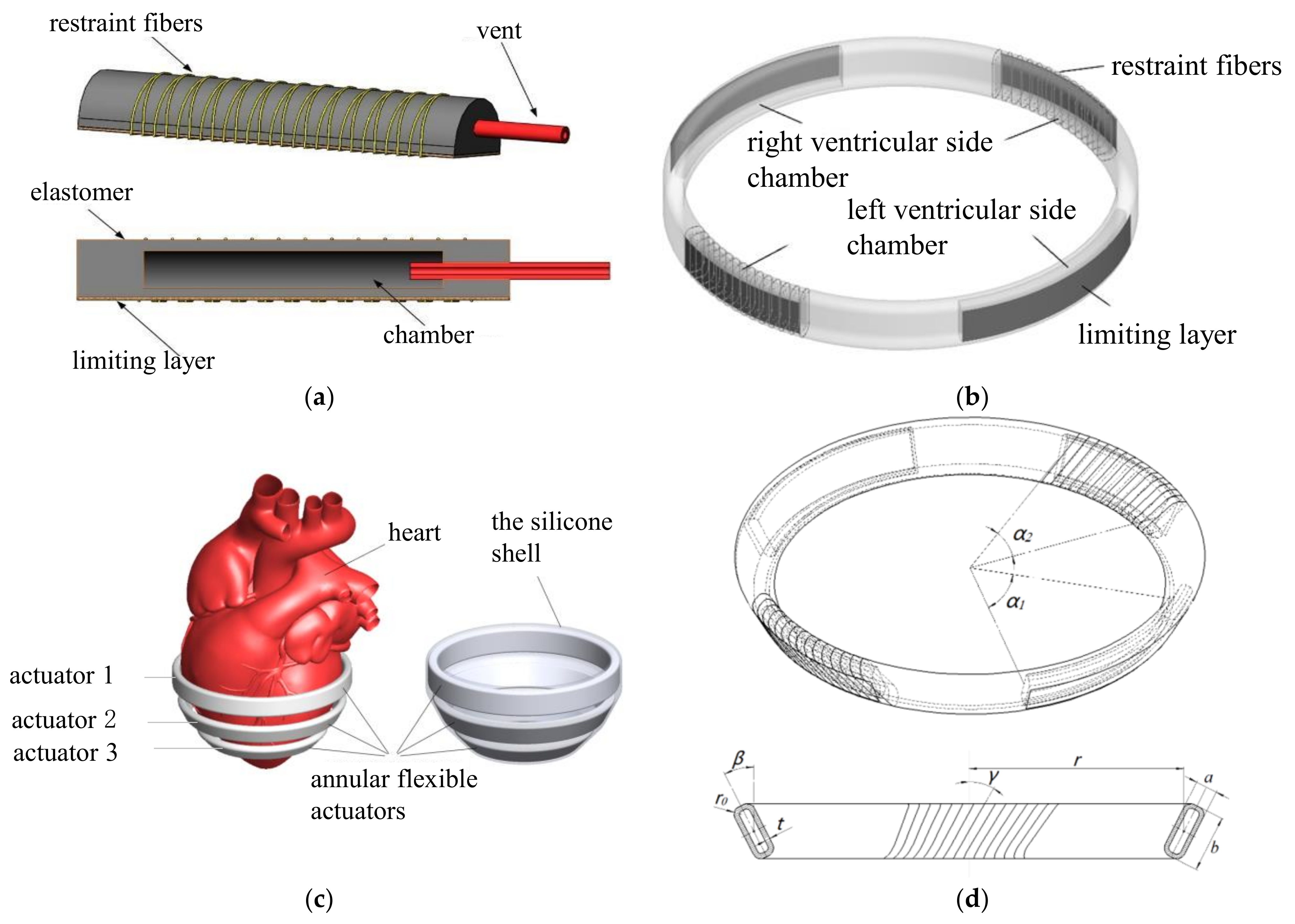
2.1. Structural Design of Fiber-Constrained Flexible Actuator

The fiber-constrained actuator generally consisted of an elastomer (with an embedded chamber), a strain limiting layer and a restraining fiber (Figure 1a). The elastomer deformed under a certain pressure to complete the bending movement by limiting the deformation of the actuator surface through the strain limiting layer. The restraint fiber limited the radial expansion of the elastomer, making the actuator efficient in changing the pressure into the bending deformation of the actuator, and thereby reducing its expansion volume. More complex movements of the actuator could be achieved by varying the density and angle of the restraining fibers.
A fiber-constrained annular flexible actuator (Figure 1b) was designed based on the fiber-constrained flexible actuator drive principle. In this actuator, the left and right ventricular side chambers were used to squeeze the left and right ventricles, and a strain limiting layer was attached to the outside. The ventricular septal side chamber was used to adjust the deformation of the annular actuator, and the strain-limiting layer was attached to the outside of the chamber, while the constraint fibers were wound around it. Then, this actuator was arranged around the heart and secured with a silicone shell in order to obtain a fiber-constrained direct ventricular assist device (Figure 1c).
According to the shape and size of human heart and the existing research theories of fiber-constrained actuators, the structures and parameters of three kinds of the annular flexible actuator were determined (Figure 1d).
Figure 1. Structural design of fiber-constrained flexible actuator. (a) Fiber-constrained flexible actuator; (b) fiber-constrained annular flexible actuator; (c) arrangement of fiber-constrained annular flexible actuators and direct ventricular assist devices; (d) structural parameters of the fiber-constrained annular flexible actuator, where α1 is the ventricular balloon circumferential angle, α2 is the septal balloon circumferential angle, r is the actuator radius, a is the cross-sectional width, b is the section length, t is the balloon wall thickness, r0 is the balloon circumferential radius, β is the actuator inclination angle, γ is the fiber inclination angle and ρ is the fiber spacing.
Applsci 12 05405 g001
Some studies showed that when the same pressure was applied to the fiber-constrained pneumatic flexible actuator, the thinner the balloon wall was, the larger the bending angle became. In order to ensure the strength of the flexible actuator, the wall thickness of the chamber t = 1 mm was selected. In this study, the radius r1 of actuator 1 and the angle α1-1 of the ventricular chamber satisfied the following relationship (Equation (1)):
2 r 1 sin ( α 1 1 2 ) = h 1 2 δ
where h1 is the length of the ventricular septum at the point where it is wrapped by the annular flexible actuator 1 as h1 = 57 mm, and δ is the thickness of the left ventricular wall as δ = 9 mm.
The calculation showed that α1-1 = 58°. As the left ventricle resembled a cone, actuator 2 and actuator 3 were reduced in equal proportions, and their lateral ventricular chamber rounding angle were rounded at the same angles α1-2 and α1-3 as α1-1, such that α1-2 = α1-3 = α1-1 = α1 = 58°.
The three annular flexible actuators dimension parameters are shown in Table 1; the other parameters (fiber spacing, fiber inclination, interventricular septum side balloon rounding angle, actuator cross-sectional width) were to be optimized in Section 2.2.

2.2. Preliminary Optimization Parameters for Fiber-Constrained Flexible Actuators

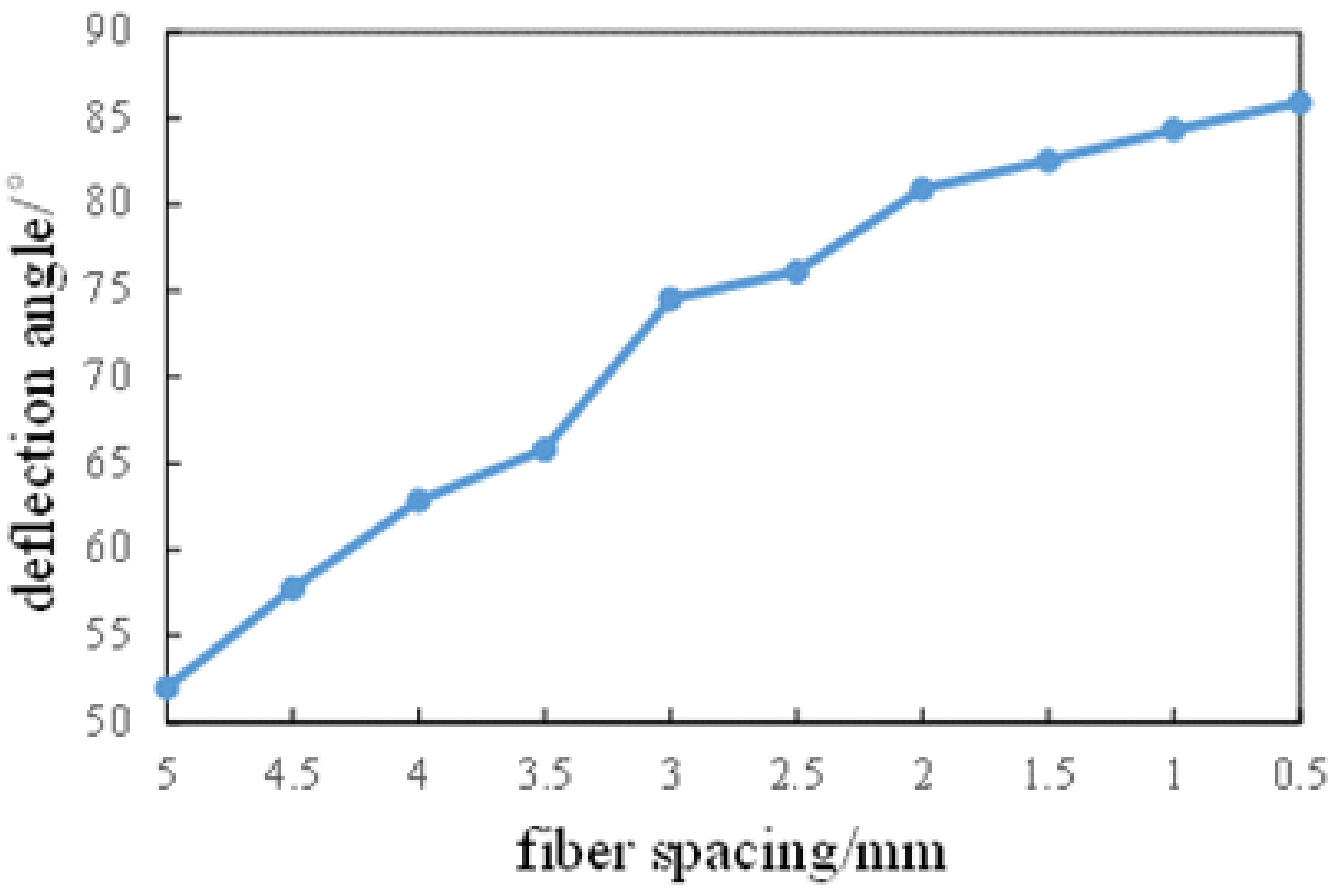
2.2.1. Preliminary Selection of the Fiber-Constrained Annular Flexible Actuator Fiber Spacing

It has been shown that the fiber spacing affects the radial expansion and bending angle of flexible actuators with semi-circular cross-sections. In order to analyze the effect of fiber spacing on the deformation of the rectangular flexible actuator, the strip flexible actuator equivalent to the annular flexible actuator chamber was established, and the fiber spacing was defined as 5 mm, 4.5 mm, 4 mm, 3.5 mm, 3 mm, 2.5 mm, 2 mm, 1.5 mm, 1 mm and 0.5 mm.

2.2.2. Preliminary Selection of the Fiber-Constrained Annular Flexible Actuator Fiber Inclination

Previous research has shown that fiber inclination has a significant effect on the bending and twisting of flexible actuators. In order to investigate the effect of fiber inclination on the deformation of the flexible actuator, fibers with inclination angles of 0°, 15°, 30°, 45° and 60° were bound to the above strip of flexible actuator on the basis of the fiber spacing setting being at 2 mm; the deformation of the flexible actuator under different fiber inclination angles was then obtained.

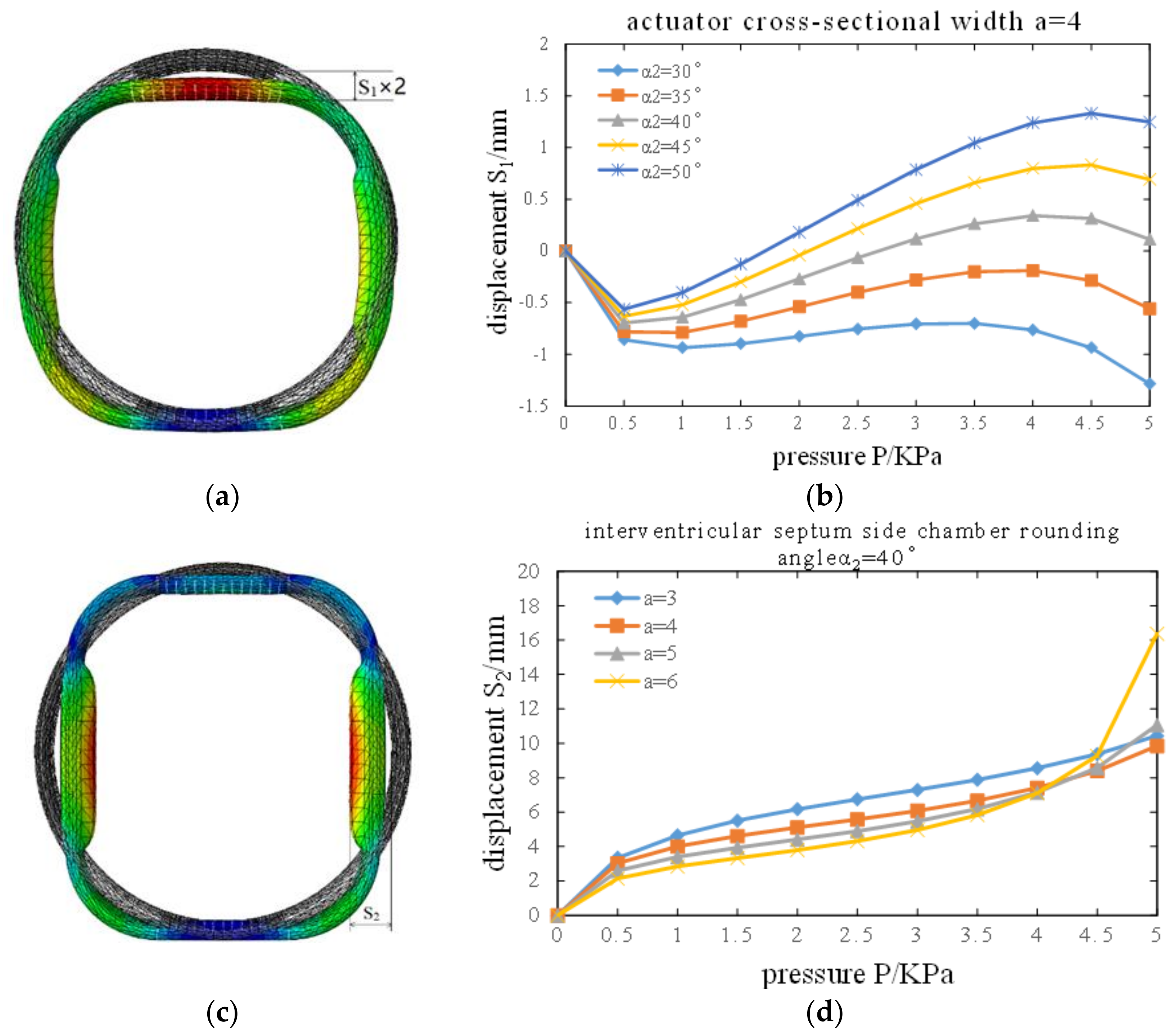
2.2.3. Preliminary Selection of the Fiber-Constrained Annular Flexible Actuator Interventricular Septum-Side Chamber Rounding Angle

During the expansion and deformation of the ventricular side chamber, the septal side chamber of the annular flexible actuator must meet two conditions in order to keep the septal side of the annular flexible actuator from being stretched, while not overly compressing the septal myocardium: (1) the septal side chamber should be as close to the heart as possible; (2) the inward displacement of the septal side chamber should not be too large in order to prevent damage to the septal myocardium. Among the many structural parameters of the flexible actuator, the factor that had a greater influence on the above two conditions was the septal chamber rounding angle.
In this paper, actuator 1 was used to investigate the effect on septal-side chamber displacement when the septal chamber rounding angle was 30°, 35°, 40°, 45° and 50°, so that a reasonable case could be judged and selected.

2.2.4. Preliminary Selection of the Fiber-Constrained Annular Flexible Actuator Cross-Sectional Width

The actuator cross-sectional width was critical to the control of output force and volume of the annular flexible actuator. Too large a cross-sectional width results in a large actuator volume, while too small a cross-sectional width results in a large output force, in order for the actuator to achieve the required displacement. In this study, we investigated the effect of actuator 1 on septal-side chamber displacement when the cross-sectional width of the actuator was 3 mm, 4 mm, 5 mm and 6 mm, in order to determine and select a reasonable size for the cross-sectional width.

2.3. Materials

The material used for the construction of the flexible system of the fiber-constrained flexible actuator designed in this study is Ecoflex00-30 silicone from Smooth-On, whose material performance parameters are shown in Table 2.
The constraint fiber was Kevlar, a material with high strength, wear resistance and extremely high tear resistance. Its parameters are as follows: strength is 3.6 Gpa, elongation modulus is 131 Gpa, elongation at break is 2.8% and axial elongation coefficient is −2 × 10⁻⁶/K.
The strain limiting layer was made of glass fiber fabric, which has good permeability and good compatibility with silicone, preventing the flexible actuator chamber from separating from the silicone when it expands and deforms.
ABAQUS has excellent simulation capabilities for non-linear finite element analysis [8]. The finite element analysis in this paper was done in the ABAQUS/Standard module. For hyper-elastic materials such as silica, description methods could usually be divided into two main categories: phenomenological models, such as the Ogden model [9] and the Yeoh model [10], and intrinsic models based on thermodynamic statistics, such as the Arruda-Boyce model [11]. The latter was not suitable for modelling flexible actuators, which required more complex models in order to capture the material properties in multiple experimental tests [12]. In this paper, the Ogden model was used to describe the material properties of Ecoflex00-30. Its strain energy could be expressed as Equation (2):
U = i = 1 N 2 μ i α i 2 λ 1 α 1 + λ 2 α 2 + λ 3 α 3 3 + i = 1 N 1 D J 1 2 i
where μi and αi are material constants, N is the number of terms in the function; λi is the principal elongation, Di is the volume deformation coefficient and J is the ratio of deformed volume to undeformed volume.
Considering silica gel as an incompressible material in this study, the principal elongations λ1, λ2 and λ3 satisfy Equation (3):
λ 1 λ 2 λ 3 = 1
This material property was investigated by Yahya Elsayed et al., whose 3rd order Ogden model coefficients [10] are shown in Table 3.
In this study, Kevlar was described using a linear elastic material model with a Young’s modulus of 31,067 MPa, a Poisson’s ratio of 0.36, a circular cross-sectional shape and a radius r set at 0.08 mm.
The strain limiting layer was a glass fiber layer, and was treated as an elastomer. The strain limiting layer was described using a shell elastic material model, with a Young’s modulus of 73,100 Mpa and a Poisson’s ratio of 0.22.
Table 2. Ecoflex00-30 material parameters.
ParametersEcoflex00-30
Forming stiffness00-30 HA
density1.07 g/cm3
Young’s modulus68.9 Kpa
Poisson’s ratio0.499
Tensile strength1378 Kpa
Fracture strain900%
Forming shrinkage3000 cps
Table 3. The third-order Ogden model coefficients of Ecoflex00-30.
μαD
2.4361 × 10−21.71393.2587
6.6703 × 10−57.06790
4.5381 × 10⁻⁴−3.36590

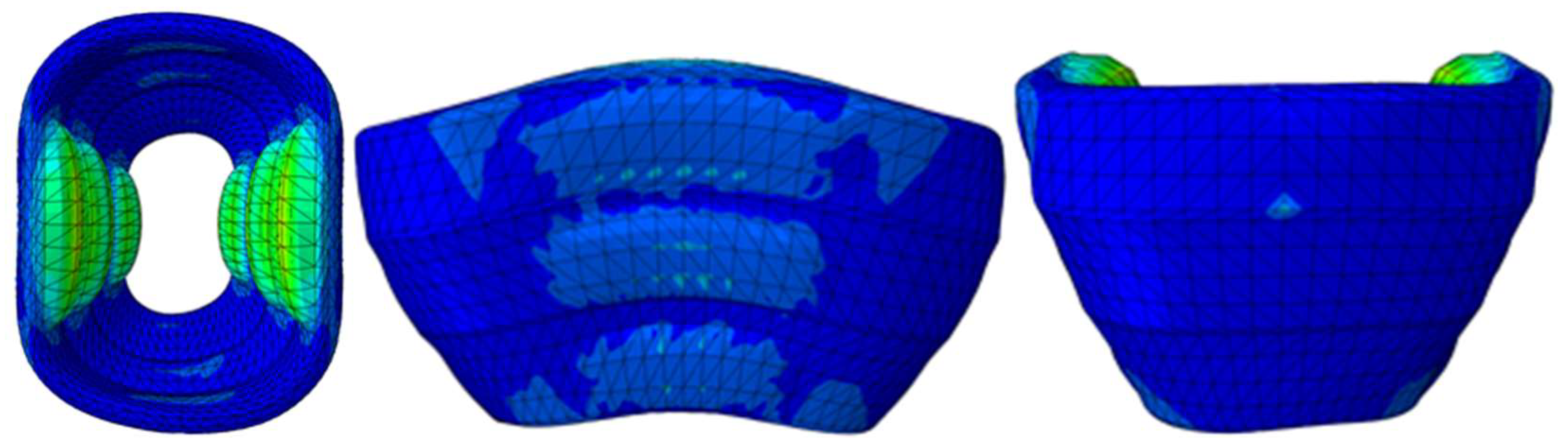
2.4. Finite Element Simulation Analysis of Fiber-Constrained Annular Flexible Actuator

In this study, SOLIDWORKS was used to construct a 3D model and imported into ABAQUS finite element simulation software, in order to carry out finite element simulation analysis of the fiber-constrained annular flexible actuator to verify whether the structure met the requirements.
The flexible actuator designed in this study was used to squeeze the heart, so it needed to have a fast response speed, and the agility of the flexible actuator (the ability to perform complex movements and execute quickly) was related to its radius of curvature. This study used the bending angle of the flexible actuator to characterize the radius of curvature as a performance indicator for the actuator. ABAQUS was used to perform a finite element analysis of the flexible actuator, with the load air pressure set at 5 Kpa, in order to observe the effect of fiber spacing and fiber inclination on the flexural capacity of the actuator.
The displacement of the chamber as it expanded determined the volume of blood expelled when the flexible actuator squeezed the heart, and whether it will cause excessive compression of the heart. It was defined as the distance between the center points of the chamber before and after the gas was introduced, with the septal-side chamber displacement denoted by S1 and the ventricular side chamber displacement denoted by S2. ABAQUS was used for the finite element analysis of the flexible actuator. The load air pressure was set to 0 Kpa, 1 Kpa, 2 Kpa, 3 Kpa, 4 Kpa and 5 Kpa; the load air pressure and its corresponding septal-side chamber displacements at different septal chamber rounding angles and ventricular-side chamber displacements at different section widths were collected.

2.5. Mechanical Performance Test Experiment of the Fiber-Constrained Annular Flexible Actuator

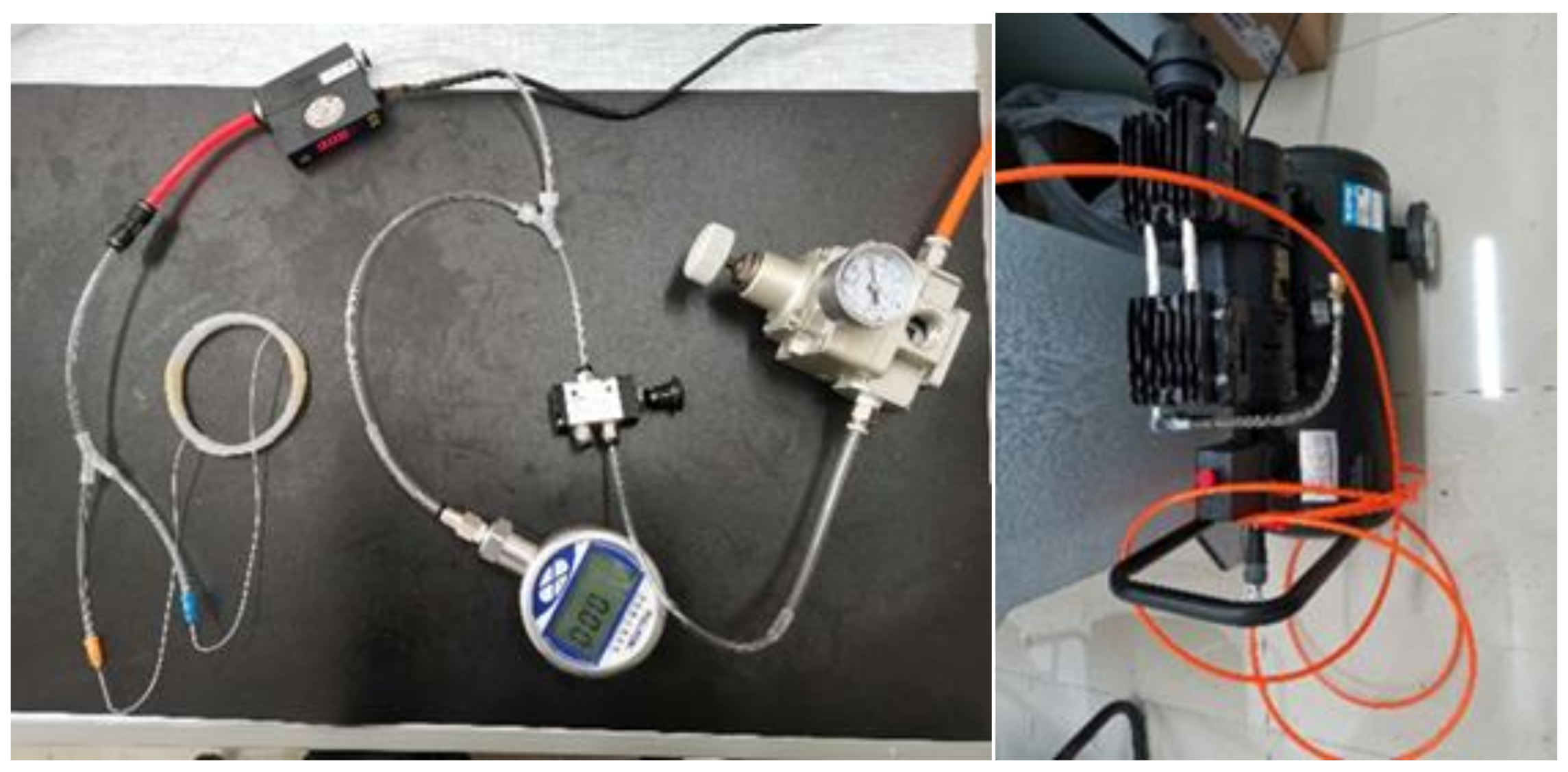
2.5.1. A Pneumatic Experiment Platform Was Built

In this study, the mechanical properties of fiber-constrained annular flexible actuators were tested, including displacement tests and output force tests. The fiber-constrained annular flexible actuator was a pneumatic device for which a pneumatic control circuit was required for mechanical performance testing (Figure 2). The compressed gas was generated by an air pump, and its output pressure was controlled by a pressure control valve which passed the output gas of the required pressure into the two inlet holes of the annular flexible actuator, thus enabling inflation of the actuator balloon.

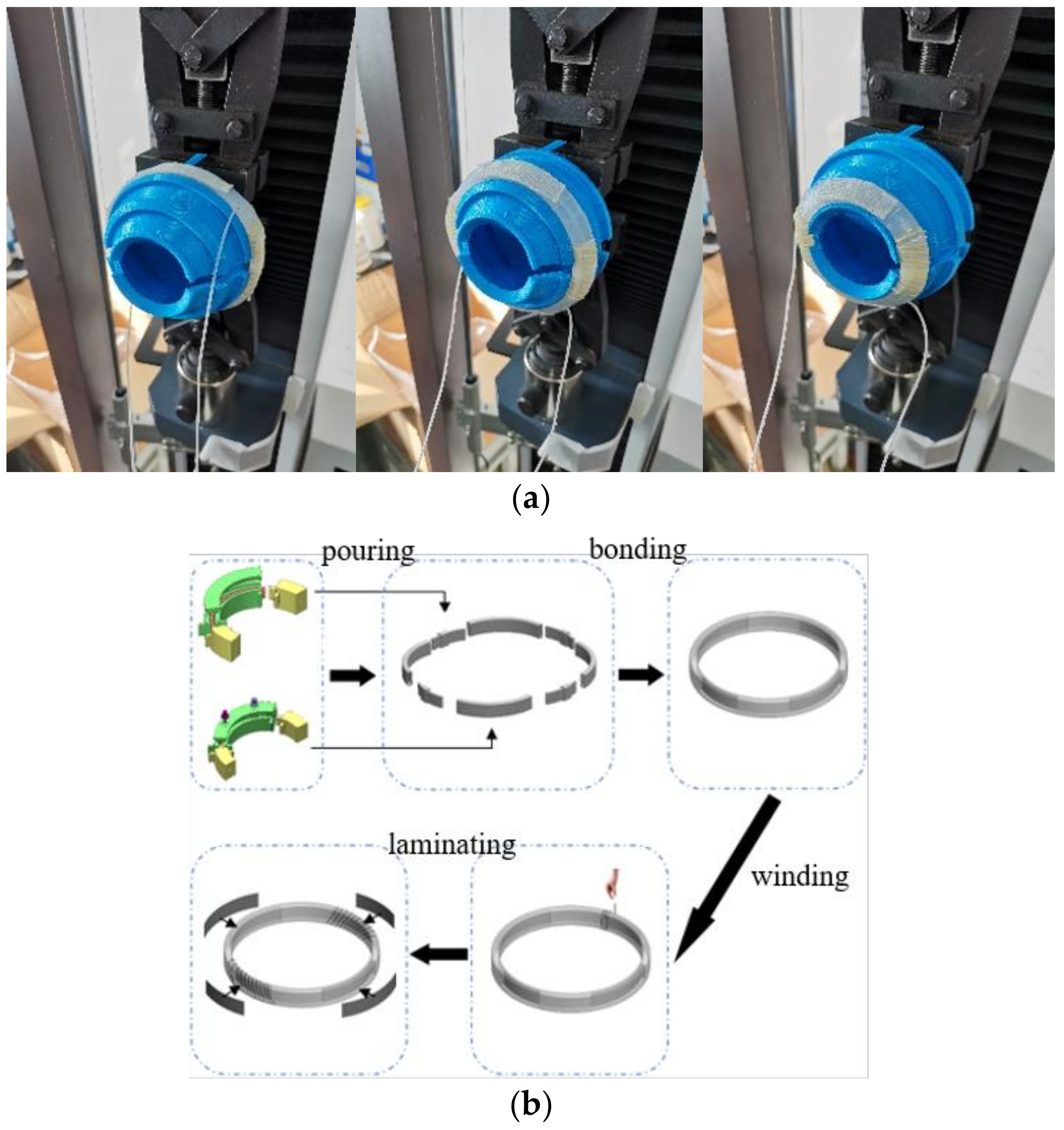
2.5.2. Fabrication of the Fiber-Constrained Annular Flexible Actuator

The flexible actuator in this study was made using mould casting, and the mould was made using 3D printing. The process was to mix the two types of silicone, A and B, at a ratio of 1:1 in a test tube; then, to centrifuge the mixture at 2000 r/min in order to defoam for one minute; then to pour the material into a pre-designed mould; and then place the mould into a vacuum chamber in order to defoam at 80 psi for 3 min. After defoaming, the mould was removed and assembled intact; then, the cast liquid silicone was cured at 70 °C for 30 min or at room temperature for more than 4 h [13], after which the cured chamber was bonded to the airway section with the same material; after, a period of curing was performed in order to form the main part of the fiber-constrained annular flexible actuator silicone rubber. After the main part was made, the Kevlar fibers were wrapped around the outside of the ventricular septum-side chamber, and the fibers were wrapped at an angle of 30°. The glass fiber fabric was then cut into squares of the same cross-sectional dimensions as the septal-side chambers and the right and left ventricular chambers, and the fabric was glued to the outside of the chambers with the formulated Ecoflex00-30 silicone rubber, resulting in the required three fiber-constrained annular flexible actuators.

2.5.3. Mechanical Performance Tests

In the displacement test, a pen was first used to mark the position of the center of the ventricular-side chamber of the fiber-constrained annular flexible actuator; then, a straightedge was placed under the annular flexible actuator, and a camera was placed above it to record the displacement at the middle mark of the ventricular side chamber during the pressurization of the annular flexible actuator. Air pressure from 0 Kpa to 5 Kpa was input into the actuator, and the displacements of the lateral ventricular chamber were recorded at different air pressures. In the output force test, the fiber-constrained annular flexible actuators were supported using the designed annular fixture (Figure 3a).The fixture was first clamped with the mechanics tester, then the annular flexible actuator was placed over the fixture in the corresponding position for each actuator. The fixture position was adjusted in order to ensure that there was no gap and no initial tension between the annular flexible actuator and the fixture. Finally, the two pneumatic inputs of the actuator were connected to the pneumatic control circuit that was built. Air pressure from 0 Kpa to 12 Kpa was input into the actuator, and the values of the output force were recorded at different air pressures.

2.6. Statistical Analysis

Statistical analysis was performed using single factor analysis of variance with SPSS software. A p value < 0.05 was considered statistically significant.

3. Results

3.1. Optimization of Structural Parameters for Fiber-Constrained Annular Flexible Actuators

The relationship between fiber spacing and deflection angle (Figure 4) was that as the fiber spacing decreased, the deflection angle simultaneously increased and gradually stabilized. When the fiber spacing was less than 2 mm, the increase in deflection angle was small, indicating that when the fiber spacing was less than 2 mm, the change in fiber winding density had little effect on the bending deformation of the flexible actuator. It has been shown that the higher the deflection angle of the actuator was, the higher the response rate of the actuator was. In order to facilitate the construction of the 3D model, the fiber spacing was set to 2 mm in the subsequent simulation; the spacing could be set to any value between 0 mm and 2 mm in the production of the real object.
The deformations of the actuator at different fiber inclination angles (Figure 5) were as follows: fiber winding at an inclination resulted in torsional deformation of the flexible actuator in the form of strips of sheets. As the fiber inclination increased, the deformation of the flexible actuator became pronounced in torsional and radial expansion, and the degree of bending decreased. In this study, since normal human epicardial myocardial fibers run in a negative left-handed spiral at 60°, the inclination of the fibers was set to 30°, which was exactly the same as the epicardial myocardium fibers. When the flexible actuator was inflated and expanded, the chamber wall was not stretched in the direction of the fibers due to the fiber restraint, which avoided strain on the myocardium as a result of deformation of the flexible actuator; therefore, the fiber inclination angle was set to 30° in this study.
Figure 4. Relationship between fiber spacing and deflection angle.
Applsci 12 05405 g004
The results of the actuator displacements at different septal-side chamber rounding angles (Figure 6a,b) showed that for the annular flexible actuator with α2 = 40°, the septal-side chamber displacement basically floated around 0 mm during pressurization to 5 Kpa, and the fluctuation was minimal. At the start of pressurization, the septal-side chamber of all the annular flexible actuators tested expanded outwards to varying degrees, but all were controlled to within 1 mm. When the pressure was increased to 0.5 Kpa, the septal-side chamber began to squeeze towards the heart, but for the α2 = 30° and α2 = 35° flexible actuators, the septal-side chamber displacement was always negative throughout the pressurization process. However, for the α2 = 45° and α2 = 50° flexible actuators, the displacement of the septal-side chamber was too large compared to the α2 = 40° annular flexible actuators, which was more likely to cause compression of the septum and damage to the myocardium; therefore, the septal-chamber angle of the annular flexible actuators was set to α2 = 40° in this study.
The results of the ventricular lateral-chamber displacements (Figure 6c,d) for different actuator cross-sectional widths showed that the ventricular lateral-chamber displacements of the four annular flexible actuators were close to a linear relationship with the pressure, when P < 4 Kpa. Under the same pressure, the larger the flexible actuator cross-sectional width, the smaller the ventricular lateral-chamber-squeeze displacement. When P > 4 Kpa, the uniform increase in pressure, the growth rate of ventricular side balloon displacement of a = 6 mm flexible actuator suddenly increased, and its deformation state began to become unstable, which would be very unfriendly to aerodynamic control in actual operation. For the choice of the other three annular flexible actuators, it was empirically clear that when the input pressure is consistent, the larger the output displacement was, the smaller the output force became. For the selection of the cross-sectional width of this kind of annular flexible actuator, the factors to be considered include volume and output force. The goal was to reduce the volume as much as possible under the condition that the output force was sufficient. As shown in the figure, the annular flexible actuator with a = 4 mm had a higher output force compared to the a = 3 mm annular flexible actuator, and a smaller size compared to the a = 6 mm annular flexible actuator. These data suggested that the annular flexible actuator cross-sectional width was set to a = 4 mm in this study.
Figure 6. Optimization results for the structural parameters of fiber-constrained annular flexible actuators. (a) Circumferential flexible actuator ventricular-side balloon displacement S1; (b) displacement of the actuator under different septal-side balloon rounding angles; (c) circumferential flexible actuator ventricular-side balloon displacement S2; (d) lateral ventricular balloon displacement at different actuator section widths.
Applsci 12 05405 g006

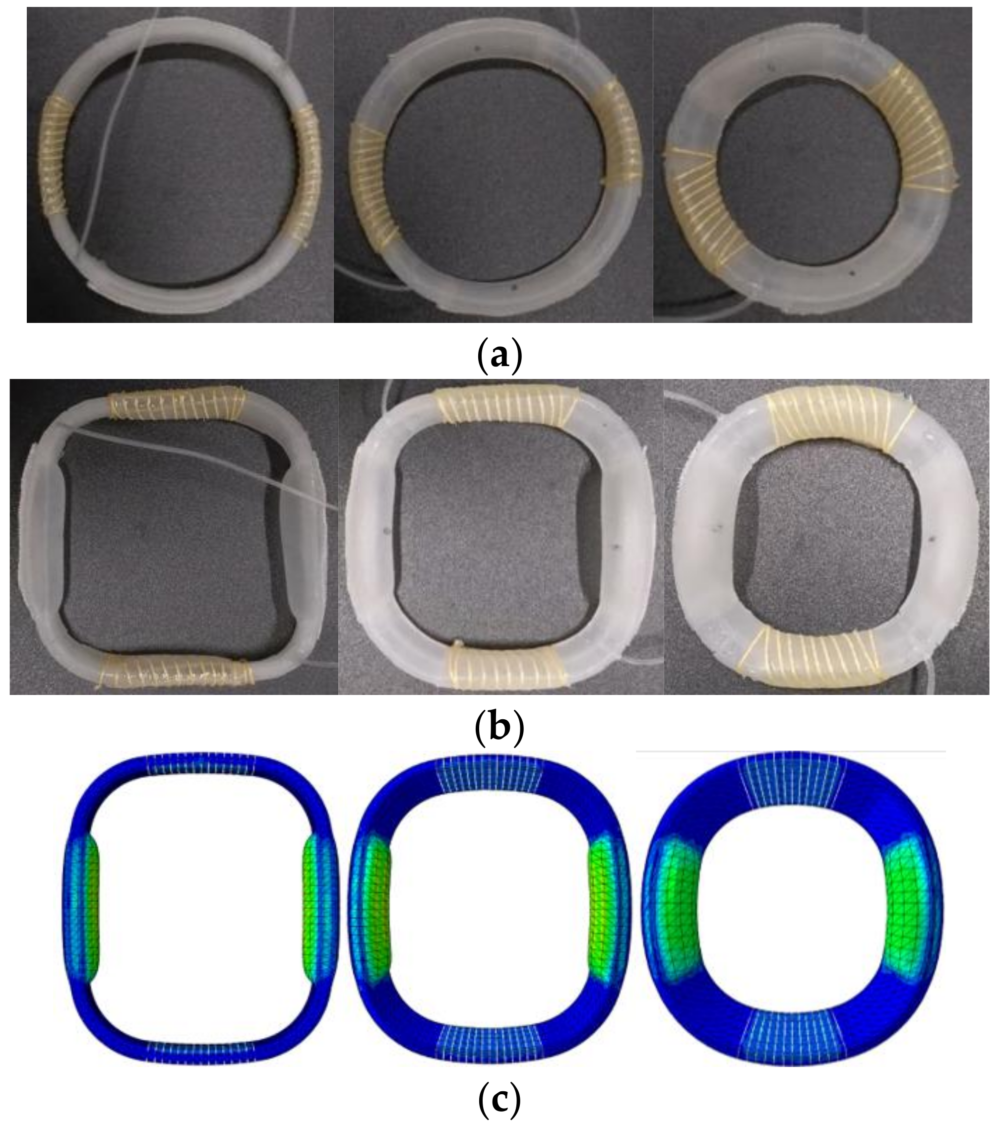
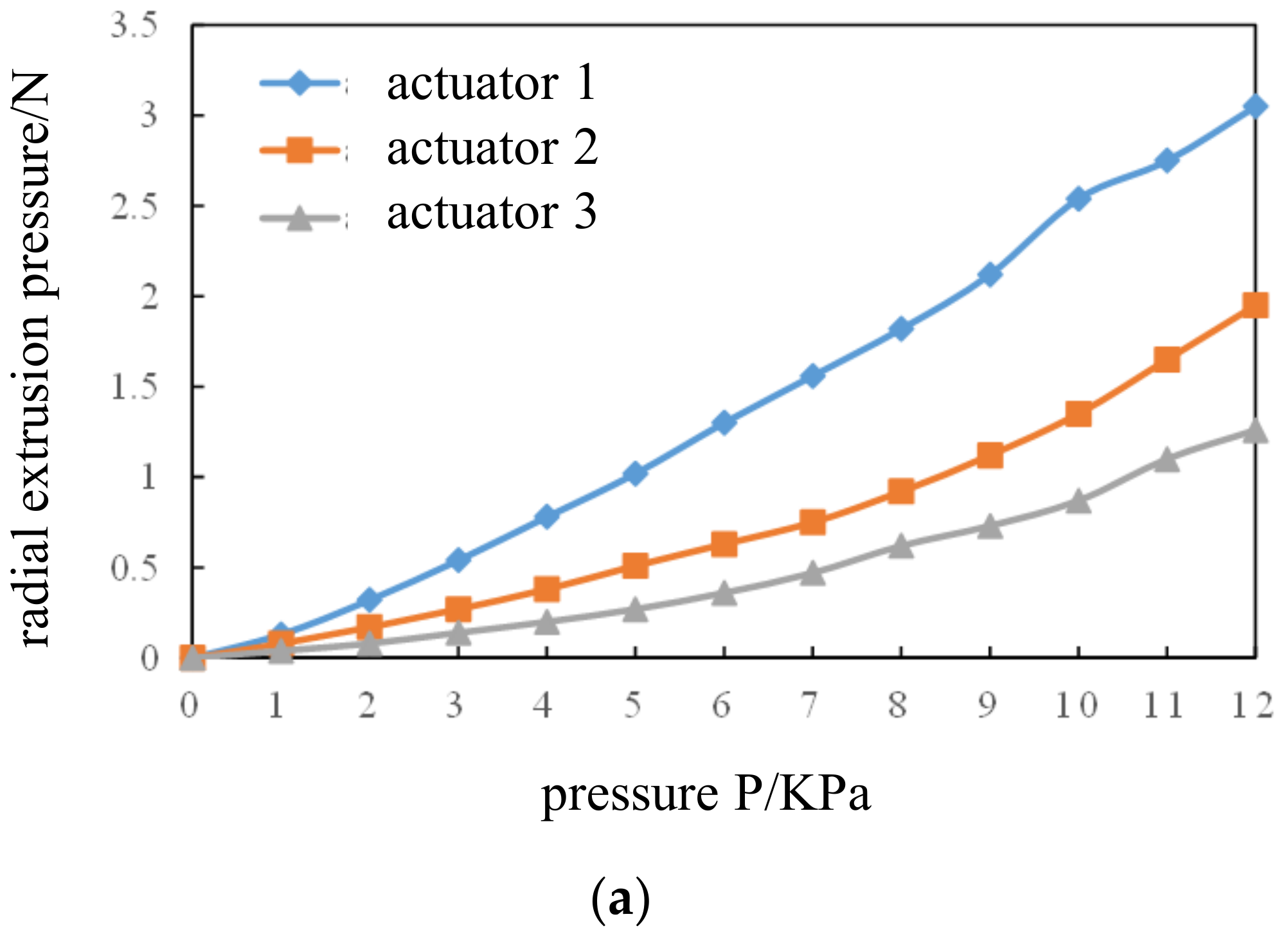
3.2. Displacement and Output Force Testing of Fiber-Constrained Annular Flexible Actuators

From the air pressure-displacement line diagram of the ventricular side of the actuator (Figure 7a,b), we found that the experimental displacement of the ventricular side of the chamber of the three fiber-constrained annular flexible actuators was basically consistent with the finite element simulation results (Figure 7c), indicating that this fiber-constrained annular flexible actuator could achieve the theoretical chamber expansion effect. As can be seen from the actuator air pressure-output force line graph (Figure 8), the input pressure and output extrusion pressure of the three actuators basically present a linear relationship; the output radial extrusion pressure under the same input pressure is actuator 1 > actuator 2 > actuator 3. However, even if a 12-kiloPascal air pressure was applied to actuator 1, actuator 2 and actuator 3, the maximum output pressure was only 3.05 N, 1.95 N and 1.26 N, which was far less than the minimum values of 77.8 N, 70 N and 50.6 N, respectively, for the maximum squeezing pressures that a normal heart could withstand [14]; it was also far less than the minimum values of 35.7 N, 32.2 N and 23.3 N, respectively, for the maximum squeezing pressures that a heart with myocardial infarction could withstand [14], such that this fiber-constrained annular flexible actuator did not cause myocardial damage when squeezing the heart.

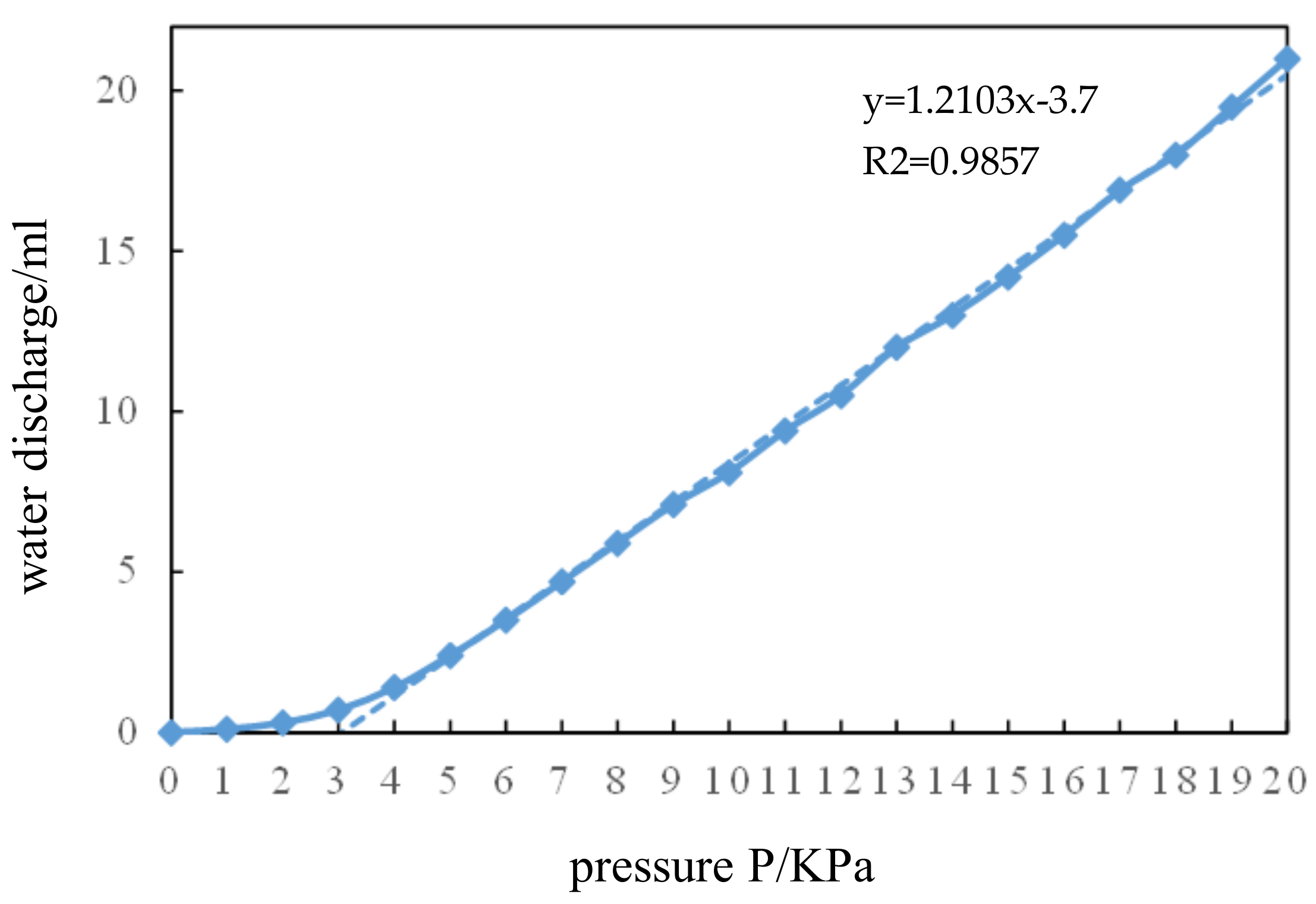
3.3. Direct Ventricular Assist Device Performance Testing

Three designed fiber-constrained annular flexible actuators were fixed together with a silicone shell and assembled into a complete direct ventricular assist device. The simulation results (Figure 9) showed that the chamber of the fiber-constrained pneumatic flexible direct ventricular assist device could achieve the desired effect of squeezing the ventricle when it expanded and flexed spontaneously towards the ventricular side. At the same time, the lateral septal chamber did not show significant radial expansion, which improved the lateral septal dilatation. Studies have shown that the contraction of the ventricles is the main power source for the heart to pump blood, and that the peak radial displacement of a normal young heart in the process of contraction was 5.39 ± 1.05 mm [15]. The air pressure-displacement relationship of the device was close to linear when assisting the heart in pumping blood (Figure 10), and the pressure range required to achieve normal radial displacement was approximately 10.6–16.38 Kpa. The discharge of the device increased slowly with increasing air pressure, and then linearly with air pressure (Figure 11). The direct ventricular assist device has a discharge of 12.83–19.82 mL within the above range of auxiliary pressure, which satisfied the requirements of two types of heart failure patients to achieve normal pumping volumes (heart failure with reduced ejection fraction: required assisted pumping volume >14.5 mL; heart failure with preserved ejection fraction: required assisted pumping volume between 0 mL and 14.5 mL).

4. Discussion

The materials used in this study for the fiber-constrained annular flexible actuator were all flexible; this allowed for an overall fully flexible design of the direct ventricular assist device while making the device lighter in weight than conventional direct ventricular assist devices, greatly reducing its size and making it less difficult to implant surgically. In the optimization of the structure of the fiber-constrained annular flexible actuator, a fiber inclination of 30° allowed the device to fit snugly into the heart during assisted compression, ensuring the stability of the output force and avoiding compression of internal organs outside the heart.
The direct ventricular assist device studied in this paper is pneumatically driven, thus the range of auxiliary pressure needs to be determined. In this paper, the relationship between displacement and driving pressure of fiber-constrained annular flexible actuators was studied. The displacement and pressure of three kinds of fiber-constrained annular flexible actuators were approximately linear. The slopes of the linear regression equation of the three actuators were 0.6369, 0.5406 and 0.42265, respectively, which indicated that under the same displacement, the relation of driving pressure was actuator 3 > actuator 2 > actuator 1. The strain and displacement of each part of the human ventricle have different peak values. According to the 17-segment division method of the American Heart Association [16], the lateral displacement peaks of the three driver positions are 9.43 ± 2.68 mm, 7.12 ± 1.98 mm and 4.91 ± 2.25 mm, respectively. The pressure ranges required by the three actuators to assist the heart in achieving lateral displacement were 14.81 ± 4.21 Kpa, 13.17 ± 3.66 Kpa and 11.51 ± 5.28 Kpa, respectively, and the normal pressure range of the device was 10.6~16.38 Kpa.
The direct ventricular assist device in this study helps the heart pump blood by squeezing it, so it is very necessary to study its pumping effect. Normal left ventricular stroke volume is 72.5~101.5 mL. When a patient has heart failure, with a declining ejection fraction and a stroke volume of less than 58 mL, the device needs to pump at least 14.5 mL more blood to get the heart pumping properly. In patients with heart failure reserved for ejection fraction, where the volume of each stroke is 58 to 72.5 mL, the device needs to assist the heart to pump at least 0 to 14.5 mL more blood in order to achieve normal pumping volume. The displacement of the device in the normal auxiliary pressure range was 12.83 to 19.82 mL, which can meet the requirements of two types of heart failure patients in order to achieve normal pumping volume.
The advantages of flexible actuator movements that were closer to natural bio-muscular movements made them of great research interest. However, as the core driving component of direct ventricular assist devices, flexible actuators have wide application prospects in direct ventricular assist devices. With the emergence of new materials and the development of driving methods, the design of flexible actuators should also become more diversified. For the fiber-constrained annular flexible actuators used in this study, it is also possible in the future to try to change the chamber distribution, muscle arrangement and fiber inclination, in order to achieve a more ideal and personalized assistance effect.

5. Conclusions

To address the current problems of infection, hemolysis and rejection in cardiac mechanical devices, and the shortcomings of early direct ventricular assist devices, a fiber-constrained annular flexible actuator was designed that could be used as a drive unit for direct ventricular assist devices, in consideration of the current research in pneumatic flexible actuators. The annular flexible actuator can provide effective compression of the ventricle, and twists at an angle (from the base of the heart towards the apex) during inflation. This twist adapts to the torsional requirements of the heart, and reduces sliding friction between the device and the heart surface, thereby reducing myocardial damage. In summary, this study may provide new ideas for the design of fully flexible direct ventricular assist devices.

Author Contributions

Writing—review: Z.Y.; data curation/methodology/software/validation/writing: C.M.; methodology/software/validation/writing: K.X.; writing—review: X.T.; validation/writing: Y.F. All authors have read and agreed to the published version of the manuscript.

Funding

This research was supported by the National Natural Science Foundation of Changsha (Grant No. kq2202074), the Natural Science Foundation of Hunan Province (Grant No. 2022JJ30696).

Institutional Review Board Statement

Not applicable.

Informed Consent Statement

Not applicable.

Data Availability Statement

Not applicable.

Conflicts of Interest

The authors declare no conflict of interest.

References

  1. Anstadt, G.L.; Schiff, P.; Baue, A.E. Prolonged circulatory support by direct mechanical ventricular assistance. ASAIO J. 1966, 12, 72–79. [Google Scholar]
  2. Wu, S.; Yang, M.; Huang, H.; Li, H. Design and in vitro testing of a non-blood contact pneumatic ventricular assist device. Chin. J. Med. Instrum. 2011, 35, 398–401. [Google Scholar]
  3. Liao, H.; Yang, M.; Zhuang, X.; Huang, H. ECG QRS wave detection and ventricular assist device control system design. J. Biomed. Eng. 2013, 30, 617–622. [Google Scholar]
  4. Roche, E.T.; Horvath, M.A.; Wamala, I.; Alazmani, A.; Song, S.; Whyte, W.; Machaidze, Z.; Payne, C.J.; Weaver, J.C.; Fishbein, G.; et al. Soft robotic sleeve supports heart function. Sci. Transl. Med. 2017, 9, eaaf3925. [Google Scholar] [CrossRef] [PubMed] [Green Version]
  5. Firouzeh, A.; Salerno, M.; Paik, J. Soft pneumatic actuator with adjustable stiffness layers for multi-dof actuation. In Proceedings of the IEEE/RSJ International Conference on Intelligent Robots and Systems (IROS), Hamburg, Germany, 28 September 2015–2 October 2015. [Google Scholar]
  6. Suzumori, K.; Iikura, S.; Tanaka, H. Flexible microactuator for miniature robots. In Proceedings of the an Investigation of Micro Structures, Sensors, Actuators, Machines and Robots, Nara, Japan, 30 January 1991; pp. 204–209. [Google Scholar]
  7. Elsayed, Y.; Lekakou, C.; Geng, T.; Saaj, C.M. Design optimization of soft silicone pneumatic actuators using finite element analysis. In Proceedings of the IEEE/ASME International Conference on Advanced Intelligent Mechatronics, Besancon, France, 8–11 July 2014. [Google Scholar]
  8. Wei, Q. ABAQUS 6.14 Super Learning Manual; People’s Posts and Telecommunications Press: Beijing, China, 2016. [Google Scholar]
  9. Polygerinos, P.; Wang, Z.; Overvelde, J.T.B.; Galloway, K.C.; Wood, R.J.; Bertoldi, K.; Walsh, C.J. Modeling of soft fiber-reinforced bending actuators. IEEE Trans. Robot. 2015, 31, 778–789. [Google Scholar] [CrossRef] [Green Version]
  10. Elsayed, Y.; Vincensi, A.; Lekakou, C.; Geng, T.; Saaj, C.M.; Ranzani, T.; Cianchetti, M.; Menciassi, A. Finite Element Analysis and Design Optimisation of a Pneumatically Actuating Silicone Module for Robotic Surgery Applications. Soft Robot 2014, 1, 255–262. [Google Scholar] [CrossRef] [Green Version]
  11. Arruda, E.M.; Boyce, M.C. A three-dimensional constitutive model for the large stretch behavior of rubber elastic materials. J. Mech. Phys. Solids 1993, 41, 389–412. [Google Scholar] [CrossRef] [Green Version]
  12. Moseley, P.; Florez, J.M.; Sonar, H.A.; Agarwal, G.; Curtin, W.; Paik, J. Modeling, Design, and Development of Soft Pneumatic Actuators with Finite Element Method. Adv. Eng. Mater. 2016, 18, 978–988. [Google Scholar] [CrossRef]
  13. Sun, Y.; Song, Y.S.; Paik, J. Characterization of silicone rubber based soft pneumatic actuators. In Proceedings of the IEEE/RSJ International Conference on Intelligent Robots and Systems, Tokyo, Japan, 3–8 November 2013. [Google Scholar]
  14. Shishido, T.; Sugimachi, M.; Kawaguchi, O. Special communication. Am. J. Physiol. Heart Circ. Physiol. 1998, 274, 1404–1415. [Google Scholar] [CrossRef] [PubMed]
  15. Li, M.; Xi, X.; Cheng, L.; Li, J.; Dong, W.; Chen, Y.; Zhi, G. MRI study of left ventricular long-axis myocardial strain characteristics in normal young people. Chin. J. Med. Imaging 2018, 26, 258–263. [Google Scholar]
  16. Cerqueira, M.D.; Weissman, N.J.; Dilsizian, V.; Jacobs, A.K.; Kaul, S.; Laskey, W.K.; Pennell, D.J.; Rumberger, J.A.; Ryan, T.; Verani, M.S.; et al. Standardized myocardial segmentation and nomenclature for tomographic imaging of the heart: A statement for healthcare professionals from the Cardiac Imaging Committee of the Council on Clinical Cardiology of the American Heart Association. J. Nucl. Cardiol. 2002, 105, 240–245. [Google Scholar] [CrossRef] [PubMed]
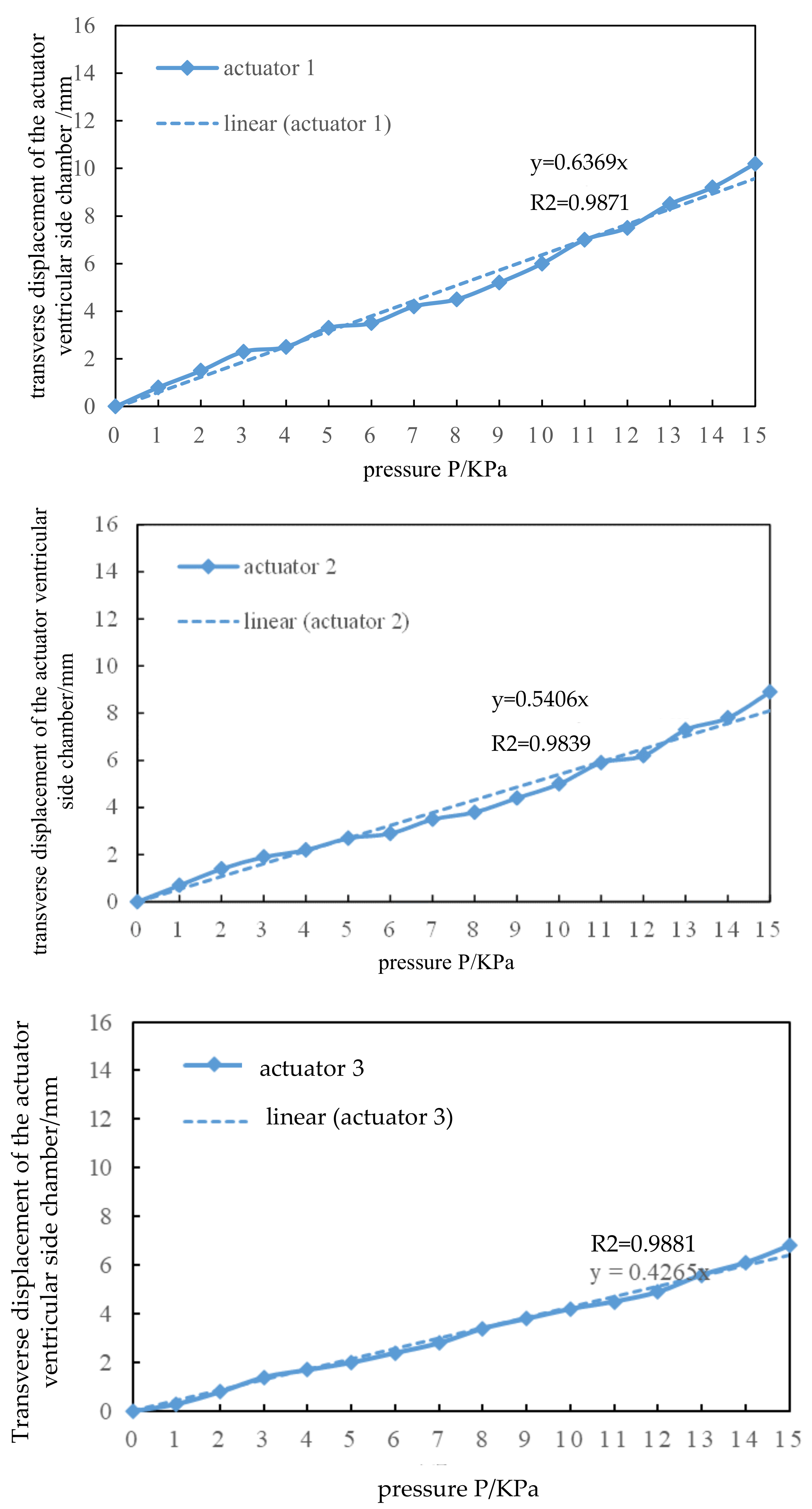
Figure 2. Pneumatic control platform for fiber-constrained annular flexible actuators.
Applsci 12 05405 g002
Figure 3. Mechanical performance test experiment of the fiber-constrained annular flexible actuator. (a) Three actuators support situations; (b) fiber-constrained annular flexible actuator fabrication process.
Applsci 12 05405 g003
Figure 5. Bending and twisting of the actuator at different fiber inclinations. (a) Fiber inclination γ = 0°; (b) fiber inclination γ = 15°; (c) fiber inclination γ = 30°; (d) fiber inclination γ = 45°; (e) fiber inclination γ = 60°.
Applsci 12 05405 g005
Figure 7. Performance testing of fiber-constrained annular flexible actuators. (a) Fiber-constrained annular flexible actuator in uninflated form; (b) fiber-constrained annular flexible actuator in inflated form; (c) simulated deformation effect of fiber-constrained annular flexible actuator.
Applsci 12 05405 g007
Figure 8. Experimental results of fiber-constrained annular flexible actuators. (a) Pressure-displacement experiment and simulation results; (b) relationship between air pressure and extrusion pressure of the three actuators.
Applsci 12 05405 g008aApplsci 12 05405 g008b
Figure 9. Deformation simulation with direct ventricular assist device.
Applsci 12 05405 g009
Figure 10. Relationship between lateral displacement and pressure of ventricular side chamber in direct ventricular assist devices. (R2 = 0.9871, R2 = 0.9839, R2 = 0.9881).
Applsci 12 05405 g010
Figure 11. Relationship between pressure input and water discharge in direct ventricular assist devices. (R2 = 0.9857).
Applsci 12 05405 g011
Table 1. Preliminary determination of the structural parameters of the fiber-constrained annular flexible actuator.
ParametersActuator 1Actuator 2Actuator 3
Ventricular chamber rounding angle α1585858
Actuator radius r/mm403626
Cross-sectional length b/mm111111
Airbag wall thickness t/mm111
Airbag corner radius r0/mm111
Actuator inclination β/°02743.2
Publisher’s Note: MDPI stays neutral with regard to jurisdictional claims in published maps and institutional affiliations.

