Article

Bionic Design of the Vertical Bracket of Wide Angle Auroral Imager by Additive Manufacturing

1
Key Laboratory of Engineering Bionics, Ministry of Education, Jilin University, Changchun 130022, China
2
Changchun Institute of Optics, Fine Mechanics and Physics, Chinese Academy of Sciences, Changchun 130022, China
3
Department of Mechanics, School of Mechanical and Aerospace Engineering, Jilin University, Changchun 130022, China
4
China Key Laboratory for Cross-Scale Micro and Nano Manufacturing, Ministry of Education, Changchun University of Science and Technology, Changchun 130012, China
5
State Key Laboratory of Automotive Simulation and Control, Jilin University, Changchun 130022, China
*
Authors to whom correspondence should be addressed.
Appl. Sci. 2022, 12(10), 5274; https://doi.org/10.3390/app12105274
Submission received: 23 April 2022 / Revised: 14 May 2022 / Accepted: 18 May 2022 / Published: 23 May 2022
(This article belongs to the Topic Additive Manufacturing)

Abstract

:
In the aerospace field, lightweight design is a never-ending pursuit. By integrating structural bionics and structural optimization, the vertical bracket of a wide angle auroral imager is designed and manufactured by additive manufacturing technology in this work. Initially, the classical topology optimization is utilized for the vertical bracket to find the optimal material layout and primary load carrying paths. Drawing on the width-to-diameter ratio and the bone mineral density distribution of human femur, the vertical support is designed as a bionic structure with a solid middle section and thin wall in other parts. Afterwards, size optimization is maintained for the bionic design model to obtain the optimal model. The simulation results show that the three-way eigenfrequencies of bionic optimized structure are 320 Hz, 303 Hz, and 765 Hz, respectively, which are closely approximate to the original structure. However, the mass of bionic optimized structure is reduced by 23%. Benefiting from Selective laser melting, the complex optimized design can be rapidly manufactured. The three-way eigenfrequencies of the optimized structure measured by the 0.2 g sweep tests are 307 Hz, 292 Hz, and 736 Hz, respectively. The vibration test of bionic optimized structure verifies the accuracy of the simulation results. This study indicates that the combination of structural bionics and structural optimization provides a powerful tool kit to the design of similar support structure for space applications.

1. Introduction

Light-weighting design is an extensively explored and utilized concept in aircraft, aerospace and mechanical engineering, especially in aerospace applications. In the least-weight and performance design, structural optimization is an effective method. Structural optimization is usually divided into three major ingredients: size optimization, shape optimization, and topology optimization [1,2,3]. The basic idea of topology optimization is to look for an optimal material layout in a given design domain with certain boundary conditions and constraints. Compared with size optimization and shape optimization, topology optimization has more degrees of freedom, allows for larger design space, and is one of the most promising structural optimizations [4,5,6]. It is usually used as a tool for finding efficient design concepts at the early design stage, whereas sizing and shape optimization are tools for detailed design at a later stage [7,8,9]. Recently, widely used in aircraft and aerospace field, optimization technology, particularly topology optimization, has become a highly effective tool to create innovative designs characterized by improved performance and reduced weights [10]. However, the results of topology optimization tend to be complicated and non-manufacturable. Therefore, the complexity of optimization results has become an obstacle to process and manufacture.
The research objective of aurora detection is the dynamic changes of auroral radiation, which is very beneficial to prevent catastrophic space weather. In 1967, the world’s first ultraviolet airglow spectrometer (UAS) was carried on the ogo-4 satellite launched by the United States, which opened the prelude of human space Aurora detection. In the following decades, countries have carried out the research and development of space-based ultraviolet imaging spectrometers, and obtained a large number of observation data. In November 2017, as the first space Aurora detector of China, the wide-angle Aurora imager (WAI) was launched on FengYun-3 D satellite, which filled the gap in the field of Aurora Observation in the far ultraviolet band. Generally, the structure of the wide-angle imager is designed according to the overall design requirements and experience, and the lightweight requirements are met by local hole removal and reinforcement. With the increasingly complex aerospace environment and increasingly harsh design conditions, traditional design methods are facing severe challenges [11,12,13].
Structural bionics sets up a bridge between biological structures and engineering structures. Drawing inspiration from the mechanical characteristics and special structures of organisms, structure behavior of existing engineered products can be improved. Researchers have conducted in-depth research on the practice of different organisms in nature in engineering [14]. Jiao et al. took the reed stalks and bamboos with hollow stem node structures in nature as bionic prototypes. The structural characteristics of the stalk were extracted, and the design of the bionic tower was carried out. The results of finite element analysis and experimental verification shown that the structural rigidity and structural strength of the bionic tower and the prototype tower were improved [15]. Liu et al. took Wang Lian as the bionic prototype to analyze the morphological characteristics and distribution rules of the leaf vein branch structure. They carried out a structural optimization bionic design for the distribution form of the internal ribs of the aircraft cover. The simulation results showed that the bionic type reduced the mass of the prototype cover plate and improved the specific strength, structural efficiency, and static performance [16]. Maier et al. presented a new method of abstraction and specialization of natural microstructure for lightweight components by using topology technology. The combination of bionics in machinery provided a new theory and method of structural design for the design process [17].
As the only rigid support component, the skeleton of animal lower limbs has certain strength and stiffness in the process of movement [18]. At present, studies have been carried out on the long bone of lower limbs, from many aspects, such as the microstructure of bone [19,20], the movement form of organism [21,22,23], the morphological and structural characteristics of bone [24], the change of geometric properties of bone section, finite element simulation analysis, and so on [25,26,27]. The above research was mainly aimed at the biological characteristics of the long bones of the lower limb, but the research on the optimization of aerospace support structure design combined with relevant characteristics had not been carried out yet.
The emergence of additive manufacturing technology provides convenience for the preparation of complex structure. After more than 30 years of academic research and practical applications, AM had developed Stereolithography (SLA), Selective Laser Sintering (SLS), Selective Laser Melting (SLM), Fused Deposition Forming (Fused Deposition Modeling, FDM), and other technologies [28,29]. The formable structural parts by AM range from micro-nano components to large-scale structural parts of several meters [30,31,32]. Additive manufacturing (AM) offers potential solutions when conventional manufacturing reaches its technological limits, including a high degree of design freedom, lightweight design, functional integration, and rapid prototyping. AM can solve a range of problems and improve production by customization, rapid prototyping, and geometrical freedom [33]. AM can be implemented not only for prototyping but also production using different optimization approaches in design, including topology optimization, support optimization and selection of part orientation, and part consolidation. Xu et al. presented an electrothermal response optimization method of nozzle structure for multi-material RP based on fuzzy adaptive control (FAC). It eliminated the drawbacks of array nozzle clogging, stringing, and melt sagging, particularly in multi-material RP, by focusing on the electrothermal response so as to adaptively distribute thermal more accurate, rapid, and balanced [34]. Linares et al. showcased a DOE methodology to optimize the SLM parameters to achieve fatigue performance as great as that of solid 17-4Ph stainless steel [35]. Jiang et al. used the Taguchi method to optimize the printing factors to obtain the highest tensile strength of the printed PEEK object. The annealing effect on printed PEEK object and crystallinity were also investigated [36]. AM breaks through the shackles of traditional manufacturing technology with its powerful personalized manufacturing capabilities. Accordingly, it provides a solution for fabrication of structures derived from topology optimization and structural bionics.
Here we introduce a new approach to design the vertical bracket of the wide angle auroral imager by a novel combination of structural bionics and structural optimization. Firstly, topology optimization is performed for the vertical support to find the optimal material layout and primary load carrying paths. Then, we study the morphological characteristics of femur and define the overall dimension of vertical bracket with reference to the width-to-diameter ratio of human femur. Next, the internal structure of the vertical bracket is designed on the basis of the distribution of bone mineral density. This provides fast, efficient way to determine the general shape and specific dimensions of the vertical bracket. Further, size optimization is utilized to obtain the optimal model. Thanks to Selective laser melting (SLM), the bionic optimized design can be rapidly manufactured. Finally, the superiority of the bionic optimization method is proved by the results of simulation analysis and vibration test. The rest of this paper is organized as follows. In Section 2, the original structure design of the vertical bracket is accomplished. In Section 3, the bionic optimization design of the vertical bracket has been performed, including topology optimization, bionic structure design and size optimization. In Section 4, mechanical analysis of the original structure design and the bionic optimization of the vertical bracket are completed and the simulation results are contrasted. In Section 5, the additive manufacturing process and experimental verification of the vertical bracket are introduced in detail. The conclusion is given in Section 6.

2. Original Structure Design of the Vertical Bracket of Wide Angle Auroral Imager

Generally, the vertical bracket of the wide-angle imager needs to be specifically designed based on experience according to the overall design input. The tracking shafting of the wide-angle imager is composed of two independent shafting: the fixed shafting and the drive shafting. The top of the vertical bracket needs to provide installation interfaces for them respectively. A rotatable imaging system is installed in the middle of the tracking shaft system, and the vertical bracket needs to provide enough space for the imaging system. The bottom surface of the vertical bracket is the interface surface between the vertical bracket and the satellite platform, with 12 screw holes evenly distributed. Therefore, the upper part of the vertical support adopts U-shaped structure, and the lower part adopts cone-shaped structure, which is reinforced with inclined stiffeners to improve the stability. A plurality of ring stiffeners and cylindrical stiffeners are set on the cone to further improve the structural rigidity. At the same time, multiple lightweight holes are reasonably set on the conical surface, inclined stiffeners, and other parts to reduce the weight of the structure. The original design of the vertical bracket and its boundary dimensions is shown in Figure 1.

3. Bionic Optimization Design of the Vertical Bracket of Wide Angle Auroral Imager

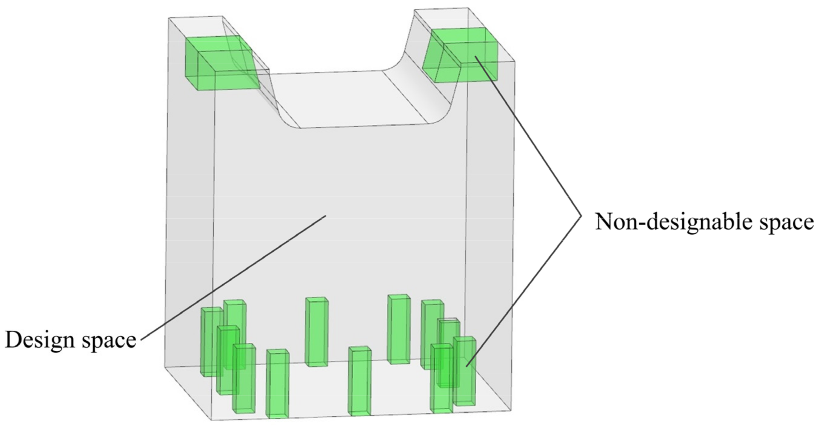
3.1. Topology Optimization Design of the Vertical Bracket

A preliminary optimization model is obtained by topology optimization. The topology-optimized design space is defined according to the original design of the vertical support. Moreover, the structural features of the holes connected with shafting and the satellite platform are the non-design space, as shown in Figure 2.
The minimization of the global compliance C is chosen as the objective function in the topology optimization procedure. The volume fraction of the solid material V ¯ is restricted, whose upper bound is set to be 0.3. In summary, the topology optimization design problem can be formulated as follows:
Find:
x = x i   i = 1 , 2 , , n
Minimize:
C = U T K U
Subject to:
K U = F V = i = 1 n x i ν i V ¯ 0 < x min x i 1 , i = 1 , 2 , 3 , , n
where, x i denotes the pseudo-density of the i -th element and n is the number of elements in the design domain. As the objective function, C represents the overall compliance of the structure. U represents the global displacement, K represents the global stiffness matrix, F represents the external load of the structure, ν i is the volume of the i -th element, V ¯ represents the volume fraction constraint, and V is the total volume of the design domain with the upper bound [37]. Under the constraint of 30% volume fraction, classical topology optimization is performed to obtain a lightweight and high-performance initial design. The optimized structural configuration of the vertical bracket of wide angle auroral imager is illustrated in Figure 3a. Based on the optimal material distribution obtained by topology optimization, the following principles should be considered: the redesign model should be approximate to the result of topology optimization; At the same time, the assembly process should be considered. For example, bolts should ensure sufficient operating space.

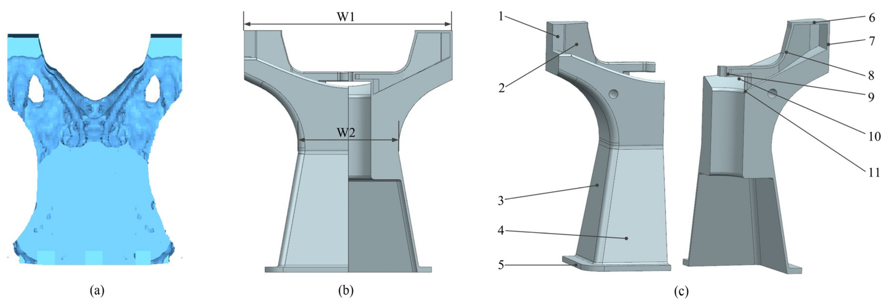
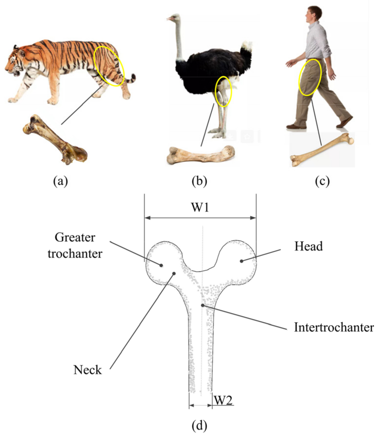
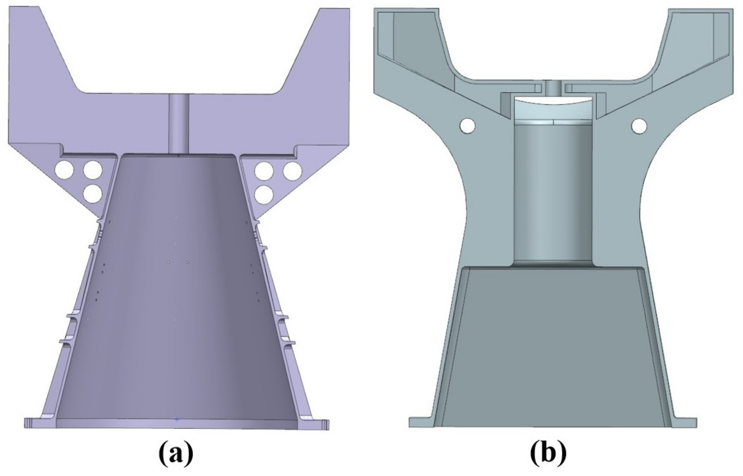
3.2. Bionic Optimization Design of the Vertical Bracket

As the only rigid support component, the lower extremity skeleton plays a bearing role during the movement process. Its strength and rigidity keep the external shape of the organism unchanged. Three typical lower limb bones including tiger, ostrich, and human are selected for research as shown in the Figure 4. Tigers, as a mammal with huge body and developed limbs, have developed lower limb bones, which are used for running and jumping (as shown in Figure 4a). The ostrich is the largest bird in the world and the only two-toed bird. Its lower limb bones are extremely load-bearing (as shown in Figure 4b). Humans are the most advanced mammals. Compared with other animals, humans have more developed lower limb bones, which are conducive to supporting body weight and completing other activities (as shown in Figure 4c).
The characteristics of these three long bones have been discovered, including (1) the top of the bone is convex at both ends and concave in the middle; (2) the top is wide and the middle part is long and narrow; and (3) all are long bones with large width-to-diameter ratio. Further research on the lower limb bones finds that although there are great differences in the body size among different groups of animals, the morphology of bone shows a certain regularity. The structures of the head and greater trochanter of the lower limb bones in humans, tigers, and ostriches are basically symmetrical, and the relative heights are almost the same.
According to the simplified diagram of human femur in Figure 4d, it can be seen that the topological structure of the vertical support is similar to the femur, which is also a symmetrical structure. The two top ends of the vertical support are convex and present a structural form of wide on the top and narrow in the middle. Taking the human femur as the reference object, the topology optimization model is further designed. Generally, the width-to-diameter ratio of the femur in adult males is 0.58–0.61 [38]. Since the width of the upper structure W1 is determined to be 460 mm, by the position of shafting system and the imaging system. The width-to-diameter ratio 0.58 is chosen, the length of the middle section W2 can be determined to be 266 mm, the size of the satellite is also determined due to it is connected to the bottom structure of the satellite. Then conical transition is adopted from the m.iddle to the bottom of the structure. It can be said that the general shape of the redesign model can be determined through the results of topology optimization. Further, the overall dimension of the redesign model can be determined through the width-to-diameter ratio of the femur, as shown in Figure 3b.
Further, the study finds that the distribution of the bone density of the femur is related to the force. Intertrochanter is located at the junction of femoral body and femoral neck, which is the part bearing the largest shear force and stress. Correspondingly, the bone density of intertrochanter is also the largest. Bone density at greater trochanter and head is lower than in the intertrochanteric region, while the lower end of the femoral body has the lowest bone density [39,40,41]. Therefore, the middle position of the vertical support is designed as a solid structure, and the upper and lower ends are designed as hollow thin-plate structures as shown in Figure 3c. As the main bearing structure, the solid structure in the middle section is designed to provide strong support for the imaging system, and the hollow thin-walled structure in the upper and lower sections is designed to minimize the structural quality. It ensures not only the lightweight of the structure, but also the rigidity of the structure.

3.3. Size Optimization

In order to obtain the optimal model, size optimization has carried on for the bionic design model of the vertical bracket. Due to the good symmetry in geometric morphology, quarter of the vertical bracket is considered as the design object. Thicknesses of 11 zones ( t i ), as shown in Figure 3c, are considered as the design variables in the size optimization. The initial values and the lower and upper bounds of all design variables are listed in Table 1. It should be mentioned that the increment of all design variables is 0.5 mm.
To reduce the structural weight as much as possible, the structural mass m is chosen as the objective function in the size optimization procedure. U represents the global displacement, K represents the global stiffness matrix, and F represents the external load of the structure. The first-order fundamental frequency f e of the bionic model should not be less than that of the original design. As for the performance constraints, the first-order fundamental frequency f e is restricted [42]. In summary, the optimal design problem may be expressed as:
Find:
t = t i , i = 1 , 2 , 3 , , 11
Minimize:
m
Subject to:
K U = F f e f e ¯ t i ¯ t i t i ¯
Table 1. Design variables in size optimization.
Zone1234567891011
Lower bound  t i ¯   (mm)111110111111
Initial value (mm)225510111111
Upper bound  t i ¯   (mm)1010151520101010101010
Optimized value (mm)4.54.54415554.56.54.54
It can be seen from the sectional profiles of the original design and the optimized design (as shown in Figure 5) that since a rotatable imaging system is installed in the middle of the tracking axis system, the upper part of the two design schemes adopts U-shaped structure, which is convenient for the rotation of the imaging system. The upper part of the original design adopts solid structure, the lower part adopts conical structure, and inclined stiffeners are used to strengthen the structural stiffness. The optimized design draws inspiration from the femur and refers to the shape of the femur. The upper structure is convex at both ends and concave in the middle. The upper and lower parts are wide and the middle is narrow. Further, according to the distribution of femur bone density, it is determined that the middle part is a solid structure, and the upper and lower parts are thin-walled structure. Then, the optimal size of each section is determined by size optimization, and the optimal design scheme is obtained. A comparison of the original and optimized designs is illustrated in Table 2. The mass of the original structure and the bionic optimized structure are 11.2 kg and 8.6 kg, respectively. Benefiting from structural optimization and bionic optimization design, the mass of the vertical bracket is reduced by 23% compared with the original design.
Table 2. Comparison of original and optimized designs.
DesignOriginal DesignFinal Design
Mass (kg)11.28.6

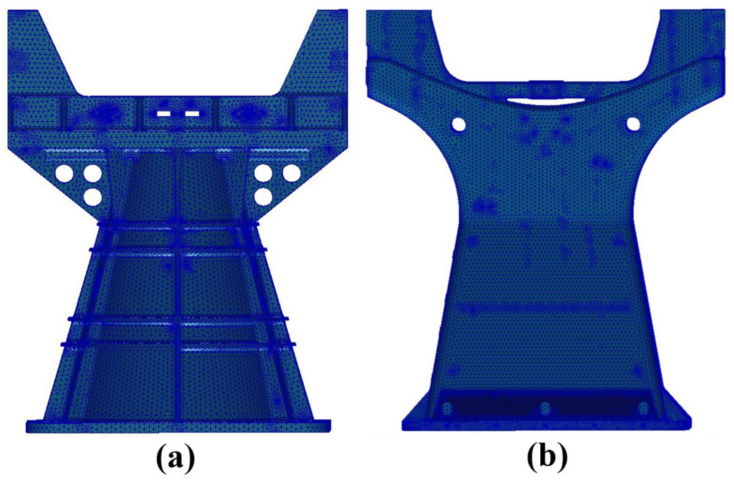
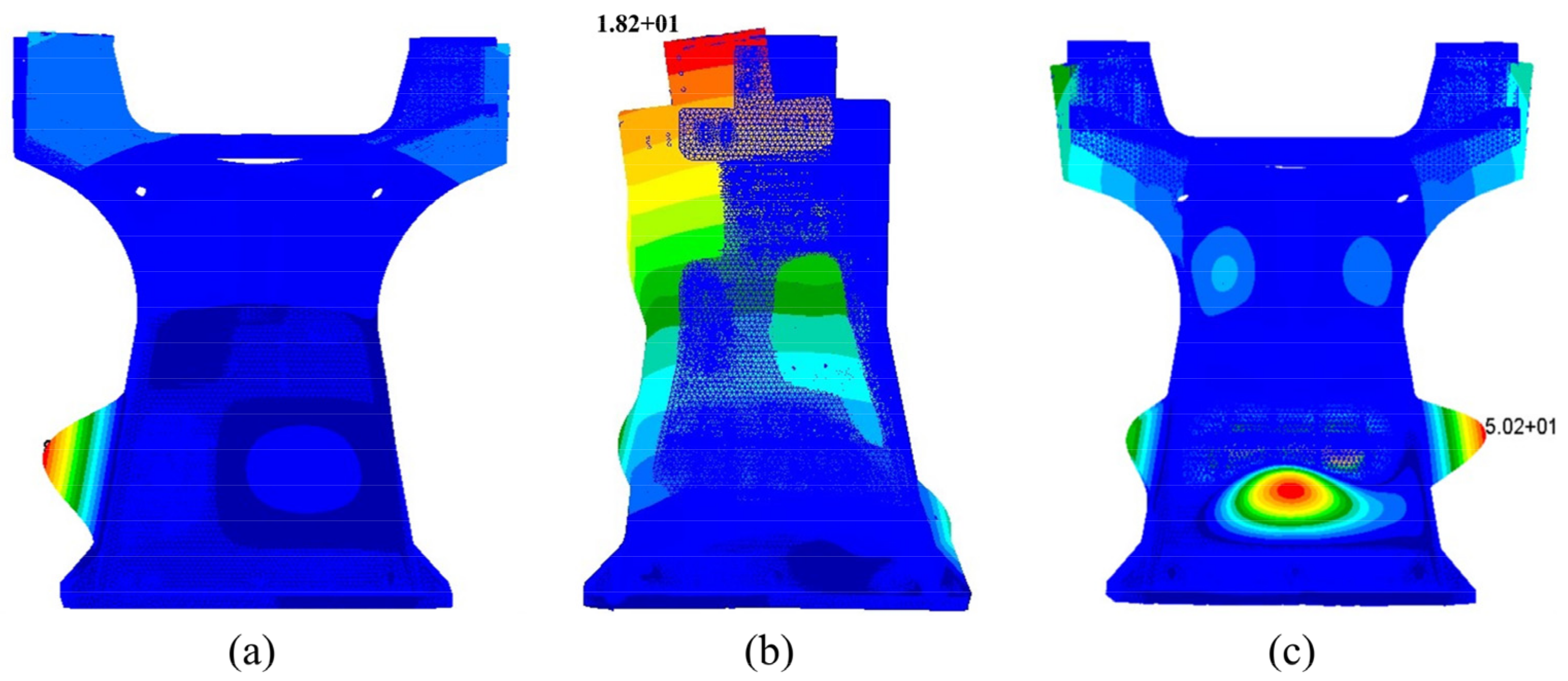
4. Mechanical Analysis

To verify the validity of the optimized design, finite element modeling of the original design and the bionic optimization design have been completed as shown in Figure 6. MSC/patran is used to model the vertical bracket, ignoring or simplifying some subtle features that have little influence on the deformation and stress distribution of the whole structure. In order to ensure the calculation accuracy, the mesh size of 5 mm is selected for modeling. The original design and the bionic optimization design are modeled as solid units.
The selection of aerospace materials is crucial in aerospace component and system design cycles. The most common aerospace materials are aluminum alloy, carbon fiber, and titanium alloy. Due to the high specific strength, corrosion resistance, low temperature resistance, and good thermal conductivity, titanium alloy is used to manufacture the vertical bracket.
The 12 screw holes of the vertical bracket connected to the satellite plane are fully constrained. Modal analysis is performed on the finite element model for the empirical design model and optimal design model. The eigenfrequencies in the three directions are shown in Table 3. Its first three natural frequencies and vibration modes for the vertical bracket are presented in Figure 7. It can be seen that the first three natural frequencies of the original structure are closely approximate to the bionic optimized structure. But the mass of bionic optimized structure is far less than the original structure, mass ratio reaches 23%.
Table 3. Eigenfrequencies of the vertical bracket for experience and bionic optimization method.
X DirectionY DirectionZ Direction
Eigenfrequency of the original structure/Hz328300786
Eigenfrequency of the bionic optimized structure/Hz320303765

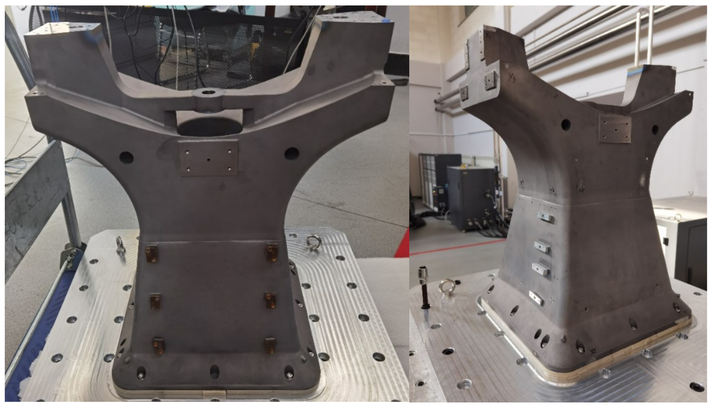
5. Manufacture and Experiments of the Vertical Bracket of Wide Angle Auroral Imager

5.1. Additive Manufacturing
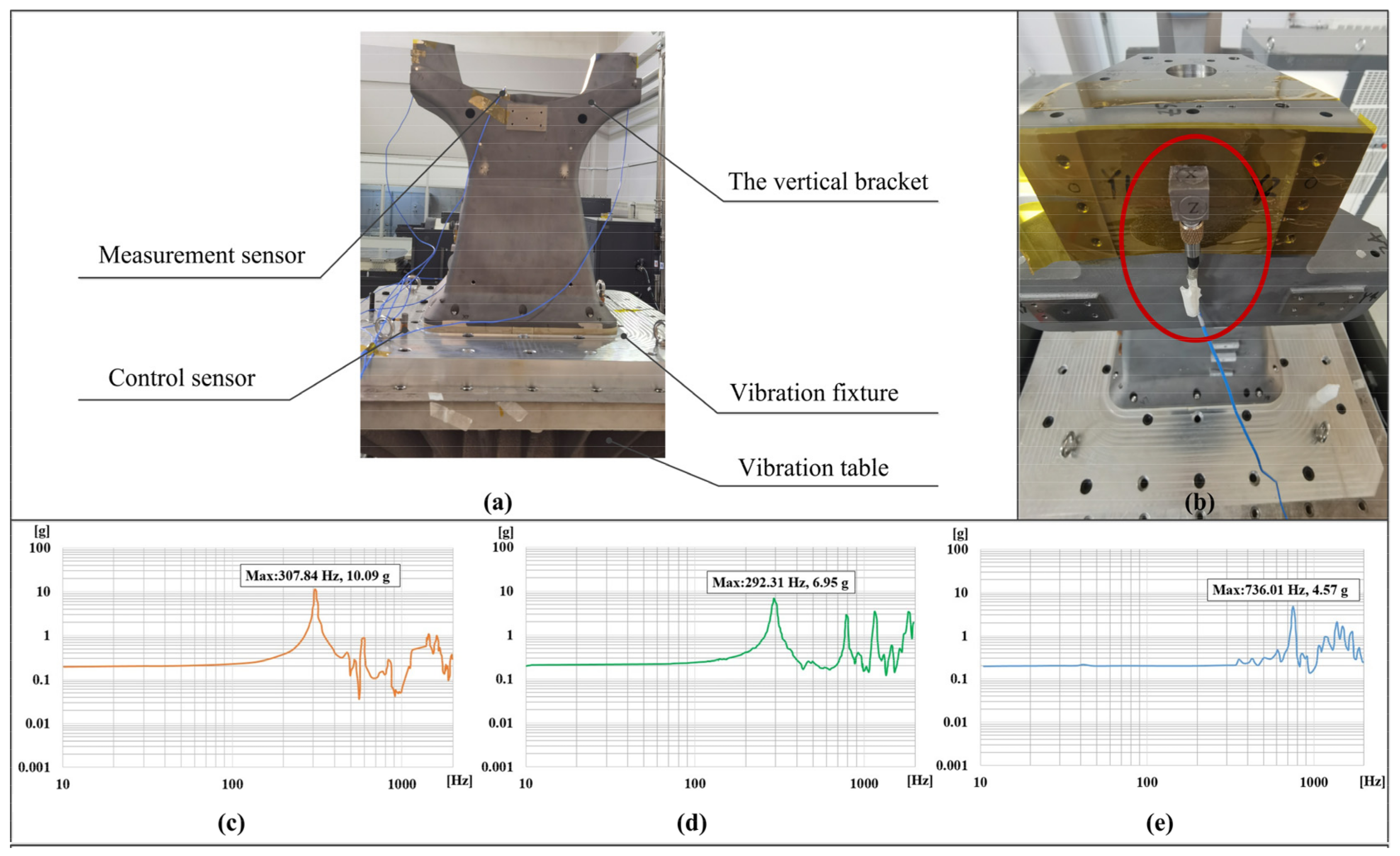
The final optimal design model of the vertical bracket is additively manufactured with titanium alloy powder, by using the BLT-S600 platform, an advanced SLM platform from Xi’an Bright Laser Technologies Co., Ltd. (BLT, Xi’an, China). The maximum dimension of BLT-S600 equipment is 600 mm × 600 mm × 600 mm, which can meet the requirements of the outer envelope of the vertical bracket. The laser power is 500 W × 4, the laser wavelength is 1060 nm–1080 nm, the maximum scanning speed is 7 m/s, and the forming accuracy of parts can be controlled within 0.2 mm. The printed model used in additive manufacturing is presented in Figure 8.

5.2. Experiments

To verify the stiffness of the structure and the accuracy of simulation result, 0.2 g sweep tests from 5–2000 Hz in three directions are selected, as shown in Figure 9a. Seven three-way sensors are arranged on the vertical bracket as shown in Figure 9b, including five measurement sensors and two control sensors, to record the response changes during the vibration test. Furthermore, the swept test curves are shown in Figure 9c–e. The comparison between the test results and the simulation results is shown in Table 4. From the first obvious peak of the sweep frequency curve, it can be determined that the three-way eigenfrequencies of the vertical bracket are 307 Hz, 292 Hz, and 736 Hz, respectively. The simulation analysis results in the same working conditions show that the eigenfrequencies in the three directions are 320 Hz, 303 Hz, and 765 Hz, respectively. The error rates of simulation and experimental results in the three directions are 4.2%, 3.7%, and 3.9%, respectively. The maximum error is 4.2%, which indicates that the accuracy of the simulation analysis results is high. The maximum error rate of simulation and experimental results in the three directions is 4.2%. The results of vibration test demonstrate that the stiffness of the structure is adequate. This optimal design scheme is viable and the performance is reliable.

6. Conclusions

In this work, we have designed the vertical bracket for wide angle auroral imager by integrating structural bionics and structural optimization and then manufactured by SLM. We have applied, for the first time, the morphological characteristics of femur to the design of aerospace supporting structure. The upper structure is convex at both ends and concave in the middle. The upper and lower parts are wide and the middle is narrow. The middle width of the vertical support is determined on the basis of the width-to-diameter ratio. According to the bone mineral density distribution of femur, the middle position of the vertical support is designed as a solid structure, and the upper and lower ends are designed as hollow thin-plate structures to meet the requirement of lightweight and structural stiffness. Structural optimization is applied in two stages of vertical support bracket design. Topology optimization is used in the conceptual design stage to find the optimal structural distribution and obtain the preliminary model of the structure. After structural bionics design, size optimization is employed to obtain the optimal structural model. Further, the feasibility of the bionic optimized design is verified by simulation analysis and experiment. Compared with the simulation analysis of the original design and the structural bionic optimized design, the first three-way eigenfrequencies of bionic optimized structure are 320 Hz, 303 Hz, and 765 Hz, which are closely approximate to the original structure. But the mass of bionic optimized structure is 8.6 kg, which is far less than the original structure. The mass ratio reaches 23%. Benefiting from SLM, the complex optimized design can be rapidly manufactured. The vibration test of the bionic optimized structure indicates the eigenfrequencies of the vertical bracket are 309 Hz, 292 Hz, and 736 Hz, respectively. The maximum error rate of simulation and experimental results in the three directions is 4.2%. This combination of structural bionics and structural optimization forms a novel approach to design support structures in the Aerospace field. This work indicates that the combination of structural optimization, structural bionic, and additive manufacturing technology provides a powerful tool kit to the design of support structures.

Author Contributions

All authors contributed to the study conception and design. Data collection, three-dimensional model, and analysis were performed by R.L., S.H., R.X. and H.W. The first draft of the manuscript was written by H.L. and all authors commented on previous versions of the manuscript. All authors have read and agreed to the published version of the manuscript.

Funding

This research is funded by the National Natural Science Foundation of China (No. 51975246), Science and Technology Development Program of Jilin Province (YDZJ202101ZYTS134), Jilin Scientific and Technological Development Program (20200404149YY), the Ascl-zytsxm (202013), the Open Project Program of Key Laboratory for Cross-Scale Micro and Nano Manufacturing, Minstry of Education, Changchun University of Science and Technology (CMNM-KF202109), the Interdisciplinary Research Fund for Doctoral Postgraduates of Jilin University (No. 101832020DJX052), and the Interdisciplinary Cultivation Project for Young Teachers and Students (No. 415010300078).

Institutional Review Board Statement

Not applicable.

Informed Consent Statement

Not applicable.

Conflicts of Interest

The authors declare no conflict of interest.

References

  1. Chintapalli, S.; Elsayed, M.S.A.; Sedaghati, R.; Abdo, M. The development of a preliminary structural design optimization method of an aircraft wing-box skin-stringer panels. Aerosp. Sci. Technol. 2010, 14, 188–198. [Google Scholar] [CrossRef]
  2. Zuo, K.T.; Chen, L.P.; Zhang, Y.Q.; Yang, J.Z. Manufacturing- and machining-based topology optimization. Int. J. Adv. Manuf. Technol. 2006, 27, 531–536. [Google Scholar] [CrossRef]
  3. Luo, J.; Gea, H.C. Optimal stiffener design for interior sound reduction using a topology optimization based approach. Vib. Acoust. 2003, 125, 267–273. [Google Scholar] [CrossRef]
  4. Wang, B.; Hao, P.; Li, G.; Tian, K.; Du, K.F.; Wang, X.J.; Zhang, X.; Tang, X.H. Two-stage size-layout optimization of axially compressed stiffened panels. Struct. Multidiscip. Optim. 2014, 50, 313–327. [Google Scholar] [CrossRef]
  5. Lu, H.S.; Horst, P. Multilevel optimization in aircraft structural design evaluation. Comput. Struct. 2008, 86, 104–118. [Google Scholar]
  6. Liu, J.K.; Ma, Y.S.; Qureshi, A.J.; Ahmad, R. Light-weight shape and topology optimization with hybrid deposition path planning for FDM parts. Int. J. Adv. Manuf. Technol. 2018, 97, 1123–1135. [Google Scholar] [CrossRef]
  7. Yldz, A.R.; Klarpa, U.A.; Demirci, E.; Doğan, M. Topography and topology optimization of diesel engine components for light weight design in the automotive industry. Mater. Test. 2019, 61, 27–34. [Google Scholar] [CrossRef]
  8. Dbouk, T. A review about the engineering design of optimal heat transfer systems using topology optimization. Appl. Therm. Eng. 2017, 112, 841–854. [Google Scholar] [CrossRef]
  9. Boccini, E.; Furferi, R.; Governi, L.; Meli, E.; Ridolfi, A.; Rindi, A.; Volpe, Y. Toward the integration of lattice structure-based topology optimization and additive manufacturing for the design of turbomachinery components. Adv. Mech. Eng. 2019, 11, 1687814019859789. [Google Scholar] [CrossRef] [Green Version]
  10. Remouchamps, A.; Bruyneel, M.; Fleury, C.; Grihon, S. Application of a bi-level scheme including topology optimization to the design of an aircraft pylon. Struct. Multidiscip. Optim. 2011, 44, 739–750. [Google Scholar] [CrossRef] [Green Version]
  11. Carruthers, G.R. Apollo 16 Far Ultraviolet Imagery of the Polar Auroras, Tropical Airglow Belt, and General Airglow. J. Geophys. Res. 1976, 81, 483–496. [Google Scholar] [CrossRef]
  12. Zhang, X.X.; Chen, B.; He, F.; Song, K.-F.; He, L.-P.; Liu, S.-J.; Guo, Q.-F.; Li, J.-W.; Wang, X.-D.; Zhang, H.-J.; et al. Wide-field auroral imager onboard the Fengyun satellite. Light Sci. Appl. 2019, 8, 494–505. [Google Scholar] [CrossRef] [Green Version]
  13. Liu, T.B.; Rajadhyaksha, M.; Dickensheets, D.L. MEMS-in-the-lens architecture for a miniature high-NA laser scanning microscope. Light Sci. Appl. 2019, 8, 527–537. [Google Scholar] [CrossRef] [Green Version]
  14. Zhao, L.; Ma, J.; Wang, T.; Xing, D. Lightweight Design of Mechanical Structures based on Structural Bionic Methodology. J. Bionic Eng. 2010, 7, S224–S231. [Google Scholar] [CrossRef]
  15. Jiao, H.; Zhang, Y.; Chen, W. The Lightweight Design of Low RCS Pylon Based on Structural Bionics. J. Bionic Eng. 2010, 7, 182–190. [Google Scholar] [CrossRef]
  16. Liu, L.B.; Chen, W.Y. Bionic design of aircraft cover plate structure based on leaf vein branch structure. J. Beijing Univ. Aeronaut. Astronaut. 2013, 39, 1596–1600. [Google Scholar]
  17. Maier, M.; Siegel, D.; Thoben, K.D.; Niebuhr, N.; Hamml, C. Transfer of natural micro structures to bionic lightweight design proposals. J. Bionic Eng. 2013, 10, 469–478. [Google Scholar] [CrossRef]
  18. Harcharan, S.R. Basic Biomechanics of the Musculoskeletal System. Am. J. Phys. Med. Rehabil. 1989, 68, 302. [Google Scholar]
  19. Nair, A.K.; Gautieri, A.; Chang, S.W.; Buehler, M.J. Molecular mechanics of mineralized collagen fibrils in bone. Nat. Commun. 2013, 4, 1724. [Google Scholar] [CrossRef] [Green Version]
  20. Malluche, H.H.; Porter, D.S.; David, P. Evaluating bone quality in patients with chronic kidney disease. Nat. Rev. Nephrol. 2013, 9, 671–680. [Google Scholar] [CrossRef] [Green Version]
  21. Ma, T.; Li, S.C.; Zheng, Q.Y. Effects of different exercise modes on bone mineral density and biomechanical indexes of growing rats. Zhejiang Sports Sci. 2009, 31, 97–101. [Google Scholar]
  22. Reilly, S.M. Locomotion in the quail (Coturnix japonica): The kinematics of walking and increasing speed. J. Morphol. 2000, 243, 173–185. [Google Scholar] [CrossRef]
  23. Yang, P.F.; Sanno, M.; Ganse, B.; Koy, T.; Brüggemann, G.P.; Müller, L.P.; Rittweger, J. Torsion and antero-posterior bending in the in vivo human tibia loading regimes during walking and running. PLoS ONE 2014, 9, e94525. [Google Scholar] [CrossRef] [Green Version]
  24. Gosman, J.H.; Hubbell, Z.R.; Shaw, C.N.; Ryan, T.M. Development of Cortical Bone Geometry in the Human Femoral and Tibial Diaphysis. Anat. Rec. Adv. Integr. Anat. Evol. Biol. 2013, 296, 774–787. [Google Scholar] [CrossRef]
  25. Michael, D.; Alexis, W.C.; Christiansen, P.; Hutchinson, J.R.; Shefelbine, S. Three-dimensional geometric analysis of felid limb bone allometry. PLoS ONE 2009, 4, e4742. [Google Scholar]
  26. Michael, D.; Yen, S.C.W.; Kłosowski, M.M.; Farke, A.A.; Hutchinson, J.R.; Shefelbine, S.J. Whole-bone scaling of the avian pelvic limb. J. Anat. 2012, 221, 21–29. [Google Scholar]
  27. Brassey, C.A.; Margetts, L.; Kitchener, A.C.; Withers, P.J.; Manning, P.L.; Sellers, W.I. Finite element modelling versus classic beam theory: Comparing methods for stress estimation in a morphologically diverse sample of vertebrate long bones. J. R. Soc. Interface 2013, 10, 142. [Google Scholar] [CrossRef] [Green Version]
  28. Kim, M.; Jacob, Z.; Rho, J. Recent advances in 2D, 3D and higher-order topological photonics. Light Sci. Appl. 2020, 9, 951–980. [Google Scholar] [CrossRef]
  29. Liang, Y.; Frederik, M.; Uwe, H.F.; Eva, B.; Martin, W. Multi-material multi-photon 3D laser micro- and nanoprinting. Light Adv. Manuf. 2021, 2, 296–312. [Google Scholar]
  30. Malinauskas, M.; Žukauskas, A.; Hasegawa, S.; Hayasaki, Y.; Mizeikis, V.; Buividas, R.; Juodkazis, S. Ultrafast laser processing of materials: From science to industry. Light Sci. Appl. 2016, 5, 11–24. [Google Scholar] [CrossRef] [Green Version]
  31. Matthias, B.; Muhammad, R.B. Hybrid multi-chip assembly of optical communication engines by in situ 3D nano-lithography. Light Sci. Appl. 2020, 9, 719–729. [Google Scholar]
  32. Paul, S.; Liang, Z.H.; Johnson, J.E.; Boudouris, B.W.; Pan, L.; Xu, X. Rapid, continuous projection multi-photon 3D printing enabled by spatiotemporal focusing of femtosecond pulses. Light Sci. Appl. 2021, 10, 1987–1997. [Google Scholar]
  33. Khorasani, M.; Ghasemi, A.H.; Rolfe, B.; Gibson, I. Additive manufacturing a powerful tool for the aerospace industry. Rapid Prototyp. J. 2021, 28, 87–100. [Google Scholar] [CrossRef]
  34. Xu, J.H.; Liu, K.Q.; Liu, Z.; Zhang, F.Q.; Zhang, S.Y.; Tan, J.R. Electrothermal response optimization of nozzle structure for multi-material rapid prototyping based on fuzzy adaptive control. Rapid Prototyp. J. 2022. [Google Scholar] [CrossRef]
  35. Linares, J.M.; Jacob, J.C.; Lopez, Q.; Spraue, J.M. Fatigue life optimization for 17-4Ph steel produced by selective laser melting. Rapid Prototyp. J. 2022. [Google Scholar] [CrossRef]
  36. Jiang, C.P.; Cheng, Y.C.; Lin, H.W.; Chang, Y.L.; Pasang, T.; Lee, S.Y. Optimization of FDM 3D printing parameters for high strength PEEK using the Taguchi method and experimental validation. Rapid Prototyp. J. 2022. [Google Scholar] [CrossRef]
  37. Wang, C.; Zhu, J.H.; Wu, M.Q.; Hou, J.; Zhou, H.; Meng, L.; Li, C.Y.; Zhang, W.H. Multi-scale design and optimization for solid-lattice hybrid structures and their application to aerospace vehicle components. Chin. J. Aeronaut. 2021, 34, 386–398. [Google Scholar] [CrossRef]
  38. Lv, L.W.; Meng, G.W.; Zhu, W.M.; Gong, H.; Zhu, D.; Zhang, X.Z. Relationships between the Three-dimension Morphologic Parameters of Proximal Femurs. In Proceedings of the BMEI: 2010 3rd International Conference on Biomedical Engineering and Informatics, Yantai, China, 16–18 October 2010; pp. 511–513. [Google Scholar]
  39. Ward, F.O. Outlines of Human Osteology. Br. Med. J. 1859, 1, 430. [Google Scholar]
  40. Song, C.H.; Yang, Y.Q.; Zhang, M.H.; Yu, J.K.; Yang, B.; Wang, D. Redesign and selective laser melting manufacturing of femoral component based on digital 3D technology. Opt. Precis. Eng. 2014, 22, 2117–2212. [Google Scholar] [CrossRef]
  41. Dane, S.; Ataturk, U. Differences between right and left-femoral bone mineral densities in right- and left-handed men and women. Intern. J. Neurosci. 2001, 111, 187–192. [Google Scholar] [CrossRef]
  42. Shi, G.H.; Guan, C.Q.; Quan, D.L.; Wu, D.T.; Tang, L.; Gao, T. An aerospace bracket designed by thermo-elastic topology optimization and manufactured by additive manufacturing. Chin. J. Aeronaut. 2020, 33, 1252–1259. [Google Scholar] [CrossRef]
Figure 1. The original structural model of the vertical bracket. (a) The structural schematic diagram. (b) Front view of the vertical bracket. (c) Side view of the vertical bracket.
Applsci 12 05274 g001
Figure 2. Geometric model for topology optimization.
Applsci 12 05274 g002
Figure 3. Optimized structural configuration of the vertical bracket. (a) Topology optimization structural configuration. (b) Bionic optimization structural configuration. (c) Size optimization structural configuration.
Applsci 12 05274 g003
Figure 4. Sketches of three typical animal lower limb bones. (a) Tiger. (b) Ostrich. (c) Human. (d) Sketch of human femur.
Applsci 12 05274 g004
Figure 5. The sectional profile. (a) The sectional profile of the original design. (b) The sectional profile of the optimized design.
Applsci 12 05274 g005
Figure 6. Finite element modeling of the vertical bracket. (a) The original model. (b) The bionic optimization model.
Applsci 12 05274 g006
Figure 7. Vibration modes of bionic optimized structure. (a) X-direction fundamental frequency. (b) Y-direction fundamental frequency. (c) Z-direction fundamental frequency.
Applsci 12 05274 g007
Figure 8. The printed model of the vertical bracket manufactured by SLM.
Applsci 12 05274 g008
Figure 9. Vibration test on the vertical bracket. (a) Schematic diagram of vibration test. (b) Schematic diagram of three-way sensor. (c) X-direction swept test curve. (d) Y-direction swept test curve. (e) Z-direction swept test curve.
Applsci 12 05274 g009
Table 4. Comparison of small-scale characteristic sweep test results and simulation results.
Directionxyz
Low-level vibration test results/Hz307292736
Simulation results/Hz320303765
Error rate4.2%3.7%3.9%
Publisher’s Note: MDPI stays neutral with regard to jurisdictional claims in published maps and institutional affiliations.

