Abstract
The geoacoustic parameter acquisition in the deep sea is of great significance to the research of ocean acoustics. This paper found that the interference structure of the shadow zone induced by the reflection of the high-speed sediment layer could be simply described by the grazing angle of the surface-bottom reflection from the theory of ray acoustics, when the source and receiver depth makes the grazing angle of the surface-bottom reflection consistent with that of the bottom-surface reflection. On this basis, a geoacoustic parameter inversion method by spatial position matching of interference fringes in the shadow zone was proposed, and an interference fringe extraction method was designed based on the maximum between-class variance algorithm in this paper. After extracting the results by the stripe coordinates in the simulation environment, the density was obtained by assuming the base sound speed as an empirical value and combining with Hamilton’s empirical formula, and the sediment sound speed and thickness were inverted by the grid search method. Those inversion results were compared with the multi-dimensional inversion results of the genetic algorithm. The simulation results showed that the fringe extraction method proposed in this paper could effectively extract the interference fringes formed by the reflection of the high-speed sediment in the shadow zone, and compared with the multi-dimensional optimization process, the relatively accurate inversion results of the sound speed and thickness of high-speed sediment could be obtained more effectively and quickly by taking the spatial position of the interference fringe as the cost function of the matching parameter combined with the grid search method in this paper.
1. Introduction
In the field of ocean acoustics, the study of ocean bottom characteristics is a popular and important subject. The influence of the ocean bottom on sound transmission cannot be ignored except for the case of deep sea sound channel transmission. However, it is difficult to measure the various acoustic properties of the ocean bottom medium, and the laboratory analysis results of the sediment sampling may be different from the real parameters of the sea sediment. So far, the geoacoustic inversion method is still the most effective means to obtain the ocean bottom characteristics [].
Geoacoustic parameter inversion is generally based on a hypothetical geoacoustic model. The corresponding cost functions by the physical quantities closely related to geoacoustic parameters are established, such as transmission loss [,,,], sound field spatial correlation [,,], pulse waveform [], ocean bottom reflection loss [,,,], etc., and then the inversion results are obtained by the comparison between theoretical values and measured values through the grid method or multidimensional optimization algorithm. However, there may be many problems of insensitivity of some parameters and multi-valued results by using a single physical quantity for inversion. Therefore, the joint inversion method has been proposed [,,]. The relatively sensitive physical quantities are selected to match different geoacoustic parameters, so that the geoacoustic parameters can be inverted independently. In recent years, in order to reduce the cost of inversion and the difficulty of experiments, the geoacoustic parameter inversion method with a single hydrophone is becoming more and more important, including extracting normal mode features from a single hydrophone using warping transform [,,,], and obtaining the range-frequency interference structure of the sound field using towed sound sources, ship noise [,,], etc. However, most of the work is concentrated in the shallow sea, and there are few studies on the geoacoustic parameter inversion in the deep sea.
In previous studies, the range-frequency interference patterns of the sound field in deep water have been based on the ray theory when the source and the receiver are near the sea surface []. An inversion method of the sound speed and thickness of sediment was proposed by using the sound field interference period in the deep sea, when the sound source is at the sea surface and the hydrophone is at the ocean bottom []. On the basis of the work above, this paper found that there is a third interference structure appearing in the shadow zone which is caused by the ocean bottom reflection for high-speed seafloor sediment, when the transceiver depth is located at the sea surface. This paper analyzed the cause of the interference structure in the shadow zone with the high-speed ocean bottom reflection by the ray theory. Based on this phenomenon, a geoacoustic parameter inversion method using the spatial position matching of the interference fringe was proposed, and the corresponding extraction method of the fringe coordinates was designed in this paper. The proposed method was preliminarily verified by simulation experiments.
Simulation results showed that the method in this paper could effectively extract the interference fringe coordinates. Combined with the grid search method, the relatively accurate and consistent sound speed and thickness of the sediment could be quickly obtained by matching the spatial position of the interference fringes in the shadow zone caused by the ocean bottom of the high-speed sediment.
2. Theory and Analysis
In the ray theory, the approximate theoretical expression of the range-frequency interference structure in the shadow zone of the deep sea is []:
where, is the sound source spectrum, is the focus factor, is the length of the sea bottom reflection path, is the radiated sound power in unit solid angle, is the ocean bottom reflection coefficient, is the time delay difference of arrival between the sea bottom primary reflection (B) and the sea surface-bottom reflection (SB), and is the time delay difference of arrival between the sea bottom-surface reflection (BS) and the sea surface-bottom-surface reflection (SBS). Equation (1) describes the two types of interference structures caused by the time delay difference of multi-path arrival in the shadow zone of the deep sea, when the depth of the sound source and the hydrophone is located at the sea surface. The change in with frequency has no effect on the sound field interference structure if the ocean bottom is regarded as a semi-infinite seafloor []. However, the actual ocean bottom has a complex stratification, especially in deep water, where a certain thickness of sediment layer is formed after long-term and stable deposition. Accordingly, it is more representative to model the ocean bottom as a two-layer seafloor. Equation (1) was applied to the situations where it was not necessary to separate water-sediment reflected ray and sediment-basement reflected ray, i.e., the thickness of the sediment layer was not too large, or the seafloor-reflected energy of the tens of meters was taken into account.
The simulation sound speed profile used the measured profile of the East Indian Ocean as shown in Figure 1, which is an incomplete sound channel. The simulation parameters were as follows: sound source frequency f = 50–1000 Hz, sound source depth sd = 200 m, receiving depth rd = 200 m, and receiving range rr = 0–25 km. Table 1 shows the simulation values of the geoacoustic parameters for the above two types of ocean bottom models.
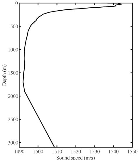
Figure 1.
The simulation sound speed profile.

Table 1.
Simulation values of geoacoustic parameters.
A third interference structure appeared in the shadow zone due to the layered structure of the ocean bottom, when the ocean bottom was modeled as two layers. Figure 2 shows the range-frequency interference structure of the deep sea under the semi-infinite ocean bottom and the two-layer ocean bottom. The results of Figure 2 were obtained by the Bellhop algorithm.
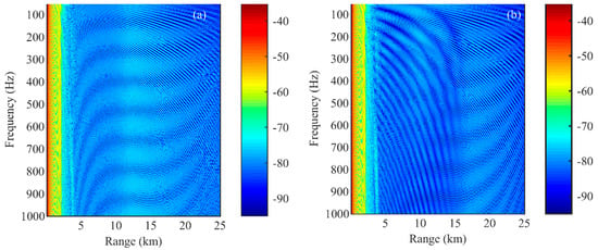
Figure 2.
Range−frequency interference structures in the deep sea, (a) semi−infinite ocean bottom, (b) layered ocean bottom.
Figure 2a shows the interference structure of two regions, including the direct wave zone in the distance of 0~5 km and the shadow zone in the distance of 5~25 km. The time delay difference of arrival between the direct wave and the primary reflected wave from the sea surface formed the interference structure in the direct wave region []. The two types of stripe structures in the shadow zone are described by and in Equation (1). Figure 2b shows a third fringe in the shadow zone caused by the two-layer ocean bottom, which was derived from the interference structure of the ocean bottom reflection coefficient in the angle-frequency domain of the layered ocean bottom. The following discussion of interference structure is mainly based on the third type of fringe caused by the layered ocean bottom with high-sound speed.
2.1. Interference Structure of Ocean Bottom Reflection Coefficient in Angle-Frequency Domain
In order to describe the interference structure caused by the layered ocean bottom in Figure 2b, the theoretical expression of the interference structure of the layered ocean bottom reflection coefficient in the angle-frequency domain was deduced in this paper.
The reflection coefficient of the two-layer ocean bottom V can be expressed as follows []:
where, is the vertical phase shift of sound waves from the seawater penetrating the sedimentary layer to the basement, is the number of acoustic waves in sedimentary layer, and and are the Rayleigh reflection coefficients of sound waves at the seawater-sediment interface and the sediment-basement interface, respectively. , , and are the sound speed, , , and are the density, and , , and are the grazing angle of sea water, sediment, and basement, respectively. is the thickness of the sedimentary layer. The high-speed sediment refers to .
The interference condition is shown as Equation (3), when the ocean bottom grazing angle is greater than the critical angle of the seawater-basement:
where, f is the frequency, and is the order of the interference fringe. When n is an odd number, it corresponds to the quarter-wave layer, and when is an even number, it corresponds to the half-wave layer. The two cases respectively correspond to the dark and bright fringes of the interference structure in the range-frequency domain of the deep sea.
When the ocean bottom grazing angle is greater than the seawater-sediment critical angle and is less than the seawater-basement critical angle, satisfies the small grazing angle condition, and the sea bottom reflection coefficient V is:
where . The interference conditions are:
Figure 3 shows the first 12-order interference fringes of the bottom reflection coefficient in the angle-frequency domain. It can be seen from Figure 3 that Equations (3) and (5) could accurately describe the interference fringes of the bottom reflection coefficient in the angle-frequency domain.
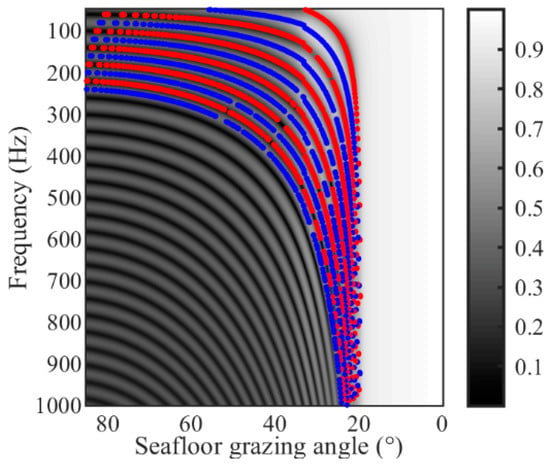
Figure 3.
The interference structure of seabed reflection coefficients in the angle-frequency domain (the red line is the quarter-wave layer (dark fringe), and the blue line is the half-wave layer (bright fringe)).
2.2. Range-Frequency Interference Structure of Shadow Zone
The distribution of the interference structure in Figure 2b is not quite identical to that in Figure 3, as the interference structure in Figure 2b is composed of the arrival energy at multiple angles, and the angle component is not singular. It can be seen from Equation (1) that the interference structure of the shadow zone is mainly composed of B, SB, BS, and SBS, the energies of these four multi-paths are similar, and the shadow zone interference structure caused by the ocean bottom reflection is complicated when simultaneously taking into account the grazing angle components of the four multi-paths.
In order to describe the interference structure with a single grazing angle, we could set a reasonable sound source and receiver depth to make the receiving grazing angles of SB and BS the same, and then the sound pressure received in the shadow zone could be approximated as []:
To simplify the derivation, the approximate form of Equation (2) can be written as follows:
is the transmission coefficient of the seawater-sediment interface. The approximate expression only slightly affects the amplitude of the ocean bottom reflection coefficient, but has no effect on the interference period caused by the two-layer seabed []. It was considered that the focus factor and slant range are almost the same. Since the transceiver depth is at the sea surface, the difference of the grazing angles of the four multi-path arrivals (B, SB, BS, and SBS) is small. It was approximately considered that , , and corresponding to the four are almost the same. Equation (6) was divided into two parts:
where, is the part which is not related to the interference of the ocean bottom reflection coefficient:
Defining , , then the coherent superposition part can be approximately expressed as:
Considering that the receiving grazing angles of SB and BS are the same, namely, , and the time delay of the two sound rays is equal, namely, , then Equation (9) can be approximately expressed as:
is the other part which is related to interference of the ocean bottom reflection coefficient:
Considering the small difference of the grazing angles of the four multi-way arrivals, it could be approximately regarded as and , Equation (12) can be approximately written as:
Due to the interference caused by the layered structure of the ocean bottom, the term appears in the coherent superposition part of Equation (7). This term results from the interference of vertical phase shifts in the sedimentary layer at different angles; however, due to the small difference of grazing angles between B, SB, BS, and SBS, namely, , it could be approximately assumed that .
Combining Equations (11) and (13), Equation (6) can be approximately expressed as:
where, is the ocean bottom reflection coefficient dominated by the grazing angle of SB, the interference structure of the shadow zone is determined by , and is the grazing angle of the sediment layer corresponding to the grazing angle of SB.
In summary, when the grazing angles of SB and BS are consistent, the sound intensity received in the shadow zone can be approximately expressed as:
For the approximation performed during the derivation, the numerical results are shown in Figure 4a–c, and the simulation parameters are consistent with Figure 2b. Figure 4a shows that the receiving grazing angles of SB and BS are approximately the same at different receiving ranges, indicating that the condition can be met at this receiving and sending depth. Figure 4b shows that and decrease with the receiving range, and is only slightly larger than , which can be further approximated to . In this case, Equation (15) is equivalent to Equation (1). In Figure 4c, 2 and ) is much smaller than and , indicating that has little effect on the interference period, and the approximation of is reasonable.
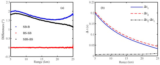
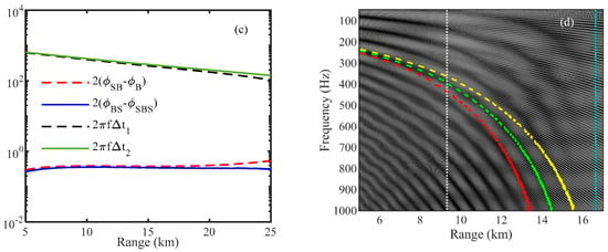
Figure 4.
(a) The difference in receiving grazing angles among the four multi−path arrivals; (b) ∆t1, ∆t2 and their difference; (c) the value changes of 2(ϕSB − ϕB) and 2(ϕBS − ϕSBS) with the receiving range, and their comparison to 2πf∆t1 and 2πf∆t2 when the frequency is 500 Hz; and (d) the description of the interference structure of the acoustic shadow zone by the interference fringe calculated by the grazing angle of each multi-path signal in combination with Equations (3) and (5) (B (red line), SB and BS (green line), SBS (yellow line), the range corresponding to the critical angle of the seawater and the basement (white dotted line), and the range corresponding to the critical angle of the sea−water and the sediment (blue dotted line)).
Figure 4d shows that the interference fringe calculated by SB (BS) grazing angle can describe the interference structure of the shadow zone in the range-frequency domain more accurately, while the interference fringe calculated by the B or SBS grazing angle cannot describe it. In terms of the energy, since the grazing angles of SB and BS are the same, the interference period of the energy after being reflected by the ocean bottom is the same, and the energy of B, SB, BS, and SBS are approximately equal, so that the total energy interference of multiple paths is determined by SB and BS. Since this paper focused on analyzing the effect of the interference structure brought by layered ocean bottom reflection and clarifying its dominant angle component, the deduced sound intensity Equation (15) and Equation (1) in the shadow zone are different in form. For the interference structure caused by the non-two-layer seabed, Equation (1) does not need to meet the condition that the source and the receiver make the grazing angle of SB and BS consistent.
3. Applications
Since the third type of interference structure in the shadow zone is formed by the ocean bottom reflection of the high-speed sediment and it is directly related to the geoacoustic parameters, it can be used for geoacoustic inversion. Using this interference structure for geoacoustic inversion has the following advantages:
1. The interference structure of the shadow zone in the range-frequency domain formed by the ocean bottom reflection of the high-speed sediment is almost the same as the interference structure of the seabed reflection coefficient in the angle-frequency domain. However, for the actual acquisition of the interference spectrum of the ocean bottom reflection coefficient in the angle-frequency domain, it is usually used by beamforming of the vertical array. Accordingly, the experiment has a high cost, and the error caused by the limited array aperture also needs to be considered []. However, the interference structure of the shadow zone in the range-frequency domain can be obtained by a single hydrophone. The grazing angle of multi-path signals varies greatly with the range, and thus it has rich angle information and does not need to consider the array aperture problem.
2. Compared with obtaining the interference structure when the hydrophone is placed on the ocean bottom, the difficulties of the experiment for geoacoustic inversion is lower when the sound source and receiver are located on the sea surface [].
Equations (3) and (5) show that the interference structure is determined by the sound speed, density, and thickness of the sedimentary layer and the sound speed and density of the basement, and it has no correlation with the ocean bottom absorption coefficient. The cost function was constructed as follows:
where and are the fringes obtained by actual measurement and the fringes calculated by Equation (3) and Equation (5), respectively, is the number of fringes, and is the grazing angle of SB receiving, corresponding to the receiving range. is the inversion parameter vector. Since the order of the fringe cannot be known in advance, the order of the fringe was also regarded as the inversion parameter, and the rest of the parameters are the same as above.
3.1. Sensitivity Analysis
Firstly, the sensitivity of Equation (16) to various acoustic parameters were analyzed. Table 2 shows the range and true value for the inversion parameters. The results of the one-dimensional sensitivity analysis of Equation (16) are shown in Figure 5.

Table 2.
Range and truevalue of parameters.
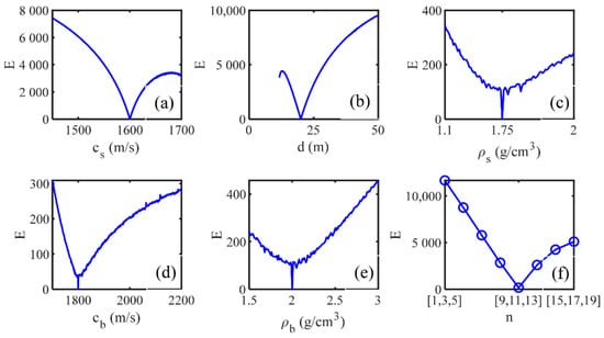
Figure 5.
One-dimensional cost function value of each inversion parameter. (a) the sound speed of the sediment (b) the thickness of the sedimentary layer (c) the density of the sediment (d) the sound speed of the basement (e) the density of the basement (f) the order of the interference fringe.
As shown in Figure 5, the value of the cost function changed greatly with , , and within the range of inversion parameters, and thus, these paraments of , , and were sensitive to the cost function. The value of the cost function varied unobviously with , , and , and thus these parameters were not sensitive to the cost function. The reason is that these three parameters of , , and are only related to in Equation (5). Compared with , they have less influence on the shifting trend of the fringe position. When the thickness is less than 10 m, the cost function value cannot be calculated because there is no corresponding fringe in the angle-frequency domain. Figure 6 shows the normalized value of the two-dimensional cost function between the parameters.
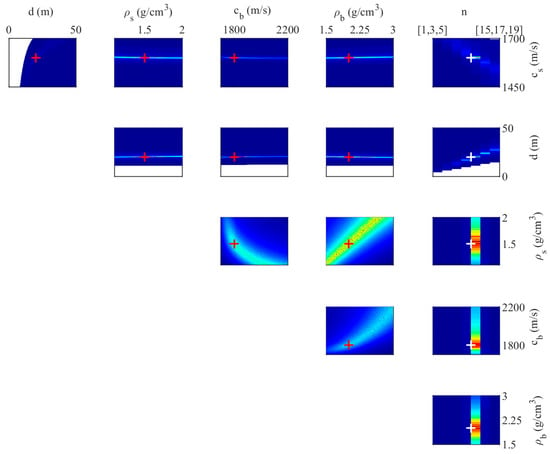
Figure 6.
The normalized value of the two-dimensional cost function of each inversion parameter (the reciprocal of Equation (7)). Red and white “+” is the true value.
The consistent results of the two-dimensional cost functions related to , , and are shown in Figure 6. The dispersion and uncertainty of the estimation results of , , and did not affect the inversion results of , , and . There was a weak value coupling among , , and . That is, when the parameters are near the truevalue, the cost function is not sensitive to the changes of the parameters, which makes it difficult to obtain accurate results of these three parameters by using Equation (16). The result is consistent with the analysis conclusion in Figure 5, that , , and are not sensitive to the cost function. During the inversion, the density could be obtained by combining Hamilton’s empirical formula and could be set as an empirical value to reduce the dimension of the inversion parameters. The inversion parameter vector becomes . So far, Equation (16) can be considered to only invert and ( is not a geoacoustic parameter).
3.2. Comparison of Inversion Results of Different Cost Functions
Equation (18) is the cost function of matching physical quantities based on the ocean bottom reflection coefficient interference period (Equation (17)). We could compare Equation (16) and Equation (18) to invert the normalized two-dimensional cost function value of and . The simulation parameters are given in Table 2.
where is the interference period extracted from the measured data, is the interference period calculated by Equation (17), is the ocean bottom grazing angle, and is the number of .
It can be seen from Figure 7 that the two-dimensional results of and in Equation (16) were more concentrated compared to the results of Equation (18). Although Equation (18) could get a more concentrated result of , the estimation result of was more dispersed. There are two reasons for the inversion results of Equation (18). One is that even if the interference period at multiple grazing angles was used for matching, the coupling between and in Equation (17) still exists. Equation (18) was comparatively insensitive to near the true value of . Equation (17) can be written as:
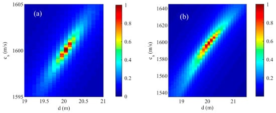
Figure 7.
The normalized value of the two-dimensional cost function of the sound speed and thickness of the sediment under two matching physical quantities (the reciprocal of Equation (7)). (a) The interference fringes of the shadow zone in range-frequency domain; (b) the ocean bottom reflection coefficient interference period.
The other reason is shown by Equation (19). When and are known, the interference period changes approximately linearly with , but changes inversely with . As shown in Figure 8, within the range of the parameter, had a much greater influence on the interference period than , and it resulted in a more dispersed estimation of .
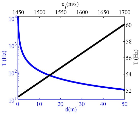
Figure 8.
Variation of T with the sound speed and thickness of the sediment within the parameter range.
For Equation (16), within the range of the parameter, the spatial position of the interference fringe of the same order changed drastically with the parameter. When the receiving range exceeded the range corresponding to the critical angle of the seawater-sedimentary layer, the spatial position of the fringe was also affected by the additional phase . Accordingly, the influence of on the spatial position of the fringe was enhanced, and Equation (16) became more sensitive to than Equation (18). Figure 5 shows that the sensitivity of Equation (16) to both and was similar. Compared with Equation (18), the influence of on in the inversion process of Equation (16) was reduced.
3.3. Interference Fringe Extraction
In order to invert and by Equation (16), we needed to extract fringes from the sound intensity interferogram in the range-frequency domain. This paper proposes a stripe extraction method, which is divided into four steps:
Step 1: since there are dark and bright fringes in the sound intensity interferogram, we performed image threshold segmentation by the maximum between-class variance method (OTSU) in the first step []. of Figure 9 is the threshold segmentation result of Figure 4d, and OTSU could be used to approximately split the stripes into two categories, bright stripes and dark stripes. Nevertheless, the two interference fringes formed by and in Equation (1) made some points in the bright and dark fringes misclassified, which could cause certain interference to the classification results.
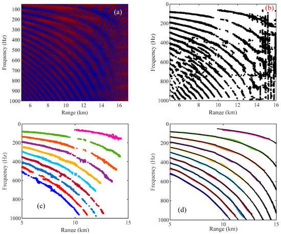
Figure 9.
The dark stripe coordinate extraction process and results; (a) the threshold segmentation result, , after OTSU; (b) the center coordinates of the dark stripes obtained after processing in step 2; (c) the center coordinates of different orders of stripes obtained after the area division; and (d) the comparison between the extraction results (colored solid lines) and theoretical results (black dotted lines).
Step 2: calculate the vertical gradient or horizontal gradient of , and select the center of the interval of gradient change as the spatial coordinate of the interference fringe. The interference period of the fringe formed by and was comparatively small, and thus the gradient change interval in the two directions was relatively small. A certain threshold can be set to filter the fine fringes. The gradient change interval of the dark stripes in in the frequency axis is:
Here, we set to 20 Hz. The frequency points of the dark stripes at each range point of were extracted by Equation (20), and the spatial position of the dark stripes could be obtained. The extracted result is shown in Figure 9b.
Step 3: the polygonal area was used to roughly split the stripes of different orders, and the stripes were recognized based on the spatial coordinates extracted in step 2 which is shown in Figure 9b. The diving result of the polygonal area with eight points is shown in Figure 9c.
Step 4: piecewise cubic Hermite interpolation polynomial (Pchip) was used to make the extracted coordinates continuous []. In order to solve the problem of floating up and down in coordinate extraction, we could obtain the average trend of the stripe coordinates by empirical mode decomposition (EMD) [] combined with the interpolation results. Figure 9d shows that the extraction result was consistent with the theoretical value as a whole, and the black dashed line is the theoretical value calculated by Equations (3) and (5).
Figure 10 shows the root mean square error (RMSE) of the extraction result in Figure 9d. Except for the 15th order fringe, the RMSE of the other fringes was 3.5 to 6 Hz. We can see from the result of RMSE that the error of the extraction method was relatively small. Nonetheless, errors existed in the extraction method, which may inevitably add some errors to the inversion results of the acoustic parameters. As for whether the inversion error caused by the extraction method was acceptable, it is discussed from the following inversion results.
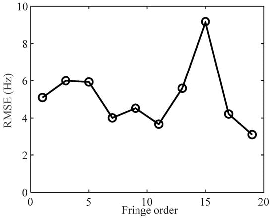
Figure 10.
The RMSE of each order fringe.
3.4. Geoacoustic Parameter Inversion
3.4.1. Inversion of Sound Speed and Thickness of Sediment by Grid Search Method
We can see that Equation (16) was not sensitive to , , and by the sensitivity analysis. Thus, was assumed as a reasonable constant and the density was obtained to reduce the inversion dimension by Hamilton’s empirical formula, and then the sensitive geoacoustic parameters were inverted by the grid search method. We selected the 7th, 9th, and 11th order fringes in the fringe extraction results in Figure 9d as the measured data, and inverted and by Equation (16). Considering the limited range in the practical towing process, we only selected the data points after the distance of 9 km. The density was obtained by combining Equation (21) with the sound speed. The was assumed to be 2000 m/s, which means was 2.28 g/cm3.
Hamilton’s empirical formula is as follows []:
, , and were inverted. The parameter range was the same as Table 2, but the truevalue of was [,,]. Figure 11 shows the inversion results of the grid search method.
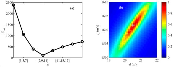
Figure 11.
Grid search inversion result; (a) the minimum cost function value under different fringe orders; (b) the normalized two-dimensional inversion results of the sound speed and thickness of the sediment layer with the fringe order [7,9,11] (the reciprocal of Equation (7)).
Figure 11a shows that could be accurately calculated by the grid search method. The white “+” in Figure 11b shows the inversion results of sound speed and thickness of seabed sediment, where was 1601.7 m/s, and was 20.5 m (the grid was 0.1 m/s and 0.1 m). The inversion error was 0.106% and 2.5%, respectively.
Judging from the concentration of the inversion results, the two-dimensional inversion results in Figure 7a were better than those in Figure 11b. This is due to the errors caused by the extraction method and the assumptions made when reducing the inversion dimension, which slightly increased the uncertainty of the inversion results of and . However, compared with Figure 7b, the inversion results in Figure 11b still had advantages. The inversion error was relatively small in terms of error. Thus, the error of the extraction method is acceptable. At the same time, if we focused on the inversion of and , we could achieve fast and comparatively accurate linear inversion based on the basement sound speed assumption and the density acquisition by the empirical formula.
3.4.2. Inversion of Geoacoustic Parameters by Genetic Algorithm
In order to compare the linear inversion results of the grid search method, the six parameters in Table 3 were inverted simultaneously by a genetic algorithm (GA) []. The values of the genetic operator were as follows: the selection probability was 0.5, the mutation probability was 0.08, the crossover probability was 0.8, and the population number was 100. To ensure that Equation (16) converges to the minimum, we set the genetic algebra to 5000 and analyzed the collected samples by posterior probability distribution (PPD). Table 3 shows the optimization range and result, the truevalue, and the error of each inversion parameter.

Table 3.
Optimization range, optimization result, truevalue, and inversion error.
The reliability of the multi-dimensional inversion results were analyzed by calculating its PDD. Firstly, we sorted the sampling values generated by GA according to the cost function value, and then utilized the Boltzmann function to weigh the probability distribution. The probability distribution of the parameters of the kth group is []:
where is the number of samples, and is the average value of the best cost function in the optimization process. The edge probability distribution of the i-th parameter value in the sample vector is:
where is the Dirac function.
The one-dimensional (1D) PPD of each geoacoustic parameter is shown in Figure 12. The red arrow shows the optimal value of the cost function. Figure 12 shows that Equation (16) was extremely sensitive to , , and . The 1D-PPD distribution of these three parameters was narrow, and the optimal value of the cost function coincided with the 1D-PPD maximum value. Meanwhile, , , and could reach the optimal value with a higher probability, which shows that the inversion result was reliable.
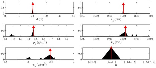
Figure 12.
The 1D-PPD (one-dimensional posterior probability distribution) of each geoacoustic parameter (the red arrow shows the inversion result corresponding to the optimal value of the cost function).
For the three parameters of , , and , their 1D-PPD distributions were comparatively dispersed and all of them converged to false parameter values. This result is consistent with the sensitivity analysis. That is, the insensitivity of Equation (16) to these three parameters caused greater uncertainty and unreliable in the inversion results of the three parameters.
In summary, it was shown that Equation (16) has a good inversion effect on and through the comparison of the inversion results using the grid search method and genetic algorithm. When the inversion target was and , we could quickly obtain relatively accurate (compared to the multi-dimensional optimization process) inversion results of and based on the grid search method and other parameter assumptions combined with empirical formulas and hypothetical empirical values.
4. Conclusions
The range-frequency domain interference structure in the shadow zone caused by the ocean bottom of the high-sound speed sediment was analyzed. We discovered that the interference structure could be depicted by a single SB (BS) grazing angle combined with the interferometric structure, the reflection coefficient of the layered ocean bottom, if the depth of launch and reception makes the grazing angles of the sea surface-bottom reflection (SB) and sea bottom-surface reflection (BS) the same. In this regard, we provided a preliminary explanation by the ray theory.
Then, we proposed to invert geoacoustic parameters by the range-frequency domain interference fringes in the shadow zone caused by the ocean bottom of the high-sound speed sediment. Compared to the interference period of the ocean bottom reflection coefficient, a more concentrated inversion result of the sound speed and thickness of the sedimentary layer could be obtained by the matching of the spatial position of the interference fringes. At the same time, we proposed a fringe extraction method based on the maximum between-class variance method. The results of this paper showed that the error of the extraction method had small error and met inversion requirements.
In the simulation environment, we linearly inverted the sound speed and thickness of the sediment by the matching of interference fringe spatial position combined with the grid search method, and compared them with the multi-dimensional inversion results of the genetic algorithm. Both the grid search method and the genetic algorithm inversion results showed that the inversion results of the sound speed and thickness of the sediment by matching the spatial position of the interference fringes were accurate, and the error was small. Focusing on the inversion of the sound speed and thickness of the sediment, the cost function proposed in this paper combined with the grid search method could quickly obtain a comparatively accurate (compared to the multi-dimensional optimization process) of the sound speed and thickness of the sediment. The future research for us is to verify our findings by real experimental data.
Author Contributions
Conceptualization, Z.L.; methodology, Z.L.; software, Z.L.; writing—original draft preparation, Z.L.; writing—review and editing, C.H. and M.Z.; funding acquisition, C.H. All authors have read and agreed to the published version of the manuscript.
Funding
This research was funded by the National Natural Science Foundation of China (No. 12004414).
Data Availability Statement
The data used to support the findings of this study are available from the corresponding author upon request.
Conflicts of Interest
The authors declare that there is no conflict of interest regarding the publication of this paper.
References
- Chapman, D.M. What are we inverting for? In Inverse Problems in Underwater Acoustics; Springer: New York, NY, USA, 2001; pp. 1–14. [Google Scholar] [CrossRef]
- Neumann, P.; Muncill, G. Using the Adaptive Simulated Annealing Algorithm to Estimate Ocean-Bottom Geoacoustic Properties from Measured and Synthetic Transmission Loss Data. IEEE J. Ocean. Eng. 2004, 29, 13–28. [Google Scholar] [CrossRef]
- Wan, L.; Zhou, J.-X.; Rogers, P.; Simmen, J.; Livingston, E.S.; Li, F.-H. Seabed Geoacoustic Inversion from Long-Range Broadband Sound Propagation in the Yellow Sea. AIP Conf. Proc. 2010, 1272, 270–277. [Google Scholar] [CrossRef]
- Wu, S.-L.; Li, Z.-L.; Qin, J.-X. Geoacoustic Inversion for Bottom Parameters in the Deep-Water Area of the South China Sea. Chin. Phys. Lett. 2015, 32, 124301. [Google Scholar] [CrossRef]
- Yang, K.; Xu, L.; Yang, Q.; Li, G. Two-Step Inversion of Geoacoustic Parameters with Bottom Reverberation and Transmission Loss in the Deep Ocean. Acoust. Aust. 2018, 46, 131–142. [Google Scholar] [CrossRef]
- Li, Z.; Zhang, R.; Yan, J.; Li, F.; Liu, J. Geoacoustic Inversion by Matched-Field Processing Combined with Vertical Reflection Coefficients and Vertical Correlation. IEEE J. Ocean. Eng. 2004, 29, 973–979. [Google Scholar] [CrossRef]
- Zhou, J.-X.; Zhang, X.-Z.; Rogers, P.; Simmen, J.; Dahl, P.; Jin, G.; Peng, Z. Reverberation Vertical Coherence and Sea-Bottom Geoacoustic Inversion in Shallow Water. IEEE J. Ocean. Eng. 2004, 29, 988–999. [Google Scholar] [CrossRef]
- Barclay, D.R.; Bevans, D.A.; Buckingham, M.J. Estimation of the Geoacoustic Properties of the New England Mud Patch from the Vertical Coherence of the Ambient Noise in the Water Column. IEEE J. Ocean. Eng. 2019, 45, 51–59. [Google Scholar] [CrossRef]
- Chapman, N.R. Perspectives on Geoacoustic Inversion of Ocean Bottom Reflectivity Data. J. Mar. Sci. Eng. 2016, 4, 61. [Google Scholar] [CrossRef] [Green Version]
- Yang, K.; Xiao, P.; Duan, R.; Ma, Y. Bayesian Inversion for Geoacoustic Parameters from Ocean Bottom Reflection Loss. J. Comput. Acoust. 2017, 25, 1750019. [Google Scholar] [CrossRef]
- Li, H.; Guo, X.-Y.; Ma, L. Estimating structure and geoacoustic parameters of sub-bottom by using spatial characteristics of ocean ambient noise in shallow water. Acta Phys. Sin. 2019, 68, 20190824, (In Chinese with English abstract). [Google Scholar] [CrossRef]
- Belcourt, J.; Holland, C.W.; Dosso, S.E.; Dettmer, J.; Goff, J.A. Depth-Dependent Geoacoustic Inferences with Dispersion at the New England Mud Patch via Reflection Coefficient Inversion. IEEE J. Ocean. Eng. 2019, 45, 69–91. [Google Scholar] [CrossRef]
- Li, Z.; Li, F. Geoacoustic inversion for sediments in the South China Sea based on a hybrid inversion scheme. Chin. J. Oceanol. Limnol. 2010, 28, 990–995. [Google Scholar] [CrossRef]
- Li, Z.; Zhang, R. Hybrid geoacoustic inversion scheme with an equivalent seabed model. J. Acoust. Soc. Am. 2012, 131, 3487. [Google Scholar] [CrossRef]
- Li, M.Z.; Li, Z.L.; Li, Q.Q. Geoacoustic inversion for bottom parameters in a thermocline environment in the northern area of the South China Sea. Acta Acust. 2020, 39, 14. [Google Scholar]
- Aunsri, N.; Michalopoulou, Z.-H. Sequential filtering for dispersion tracking and sediment sound speed inversion. J. Acoust. Soc. Am. 2014, 136, 2665–2674. [Google Scholar] [CrossRef]
- Bonnel, J.; Dosso, S.E.; Eleftherakis, D.; Chapman, N.R. Trans-Dimensional Inversion of Modal Dispersion Data on the New England Mud Patch. IEEE J. Ocean. Eng. 2019, 45, 116–130. [Google Scholar] [CrossRef] [Green Version]
- Liu, H.; Yang, K.; Ma, Y.; Yang, Q.; Huang, C. Synchrosqueezing transform for geoacoustic inversion with air-gun source in the East China Sea. Appl. Acoust. 2020, 169, 107460. [Google Scholar] [CrossRef]
- Jiang, Y.-M.; Dosso, S.E.; Bonnel, J.; Wilson, P.S.; Knobles, D.P. Passive Acoustic Glider for Seabed Characterization at the New England Mud Patch. IEEE J. Ocean. Eng. 2021, 1–12. [Google Scholar] [CrossRef]
- Weng, J.B.; Li, F.H.; Guo, Y.G. The sound field frequency-range interference patterns in deep water: Theory and experiment. Acta Acust. 2015, 41, 330–342, (In Chinese with English abstract). [Google Scholar] [CrossRef]
- Weng, J.B.; Li, F.H.; Guo, Y.G. Geoacoustic inversion based on near-field frequency-range interference pattern in deep water. Acta Acust. 2015, 40, 207–215, (In Chinese with English abstract). [Google Scholar] [CrossRef]
- Wang, P.; Song, W. Matched-field geoacoustic inversion using propagation invariant in a range-dependent waveguide. J. Acoust. Soc. Am. 2020, 147, EL491–EL497. [Google Scholar] [CrossRef]
- Brekhovskikh, B.M. Waves in Layered Media: Applied Mathematics and Mechanics; Academic Press: Cambridge, MA, USA, 1980. [Google Scholar]
- Otsu, N. A threshold selection method from gray-level histograms. IEEE Trans. Syst. Man Cybern. 1979, 9, 62–66. [Google Scholar] [CrossRef] [Green Version]
- Fritsch, F.N.; Carlson, R.E. Monotone Piecewise Cubic Interpolation. SIAM J. Numer. Anal. 1980, 17, 238–246. [Google Scholar] [CrossRef]
- Huang, N.E.; Shen, Z.; Long, S.R.; Wu, M.C.; Shih, H.H.; Zheng, Q.; Yen, N.-C.; Tung, C.C.; Liu, H.H. The empirical mode decomposition and the Hilbert spectrum for nonlinear and non-stationary time series analysis. Proc. R. Soc. Lond. Ser. A Math. Phys. Eng. Sci. 1998, 454, 903–995. [Google Scholar] [CrossRef]
- Hamilton, E.L.; Bachman, R.T. Sound velocity and related properties of marine sediments. J. Acoust. Soc. Am. 1982, 72, 1891–1904. [Google Scholar] [CrossRef]
- Gingras, D.F. Inversion for geometric and geoacoustic parameters in shallow water: Experimental results. J. Acoust. Soc. Am. 1995, 97, 3589–3598. [Google Scholar] [CrossRef] [Green Version]
- Gerstoft, P. Inversion of seismoacoustic data using genetic algorithms and a posteriori probability distributions. J. Acoust. Soc. Am. 1994, 95, 770–782. [Google Scholar] [CrossRef] [Green Version]
Publisher’s Note: MDPI stays neutral with regard to jurisdictional claims in published maps and institutional affiliations. |
© 2022 by the authors. Licensee MDPI, Basel, Switzerland. This article is an open access article distributed under the terms and conditions of the Creative Commons Attribution (CC BY) license (https://creativecommons.org/licenses/by/4.0/).