1. Introduction
In this article, we introduce the Resetting Anchor/Antenna Tether Mechanism (RAATM), which is a device designed to provide dual anchoring and antenna capabilities to autonomous underwater vehicles (AUVs). The RAATM is resettable; an AUV can anchor at one location for a period of time, retrieve the anchor, move to a new location, and redeploy the anchor. Furthermore, the RAATM tether may also be used as an antenna for radio communications while deployed; this may allow smaller AUVs to accomplish missions that would otherwise require larger AUVs with dedicated antennas. While resettable anchors have been available for vessels for thousands of years [
1], the RAATM has a unique design that is appropriate for small AUVs operating in dynamic conditions in littoral zones, coastal areas, riverine environments, and other bodies of water. The RAATM design combines an augering anchor spike with a sliding array of semi-flexible wire roots with friction-enhancing bristles embedded around the base of the anchor assembly.
Small, lightweight AUVs operating near the seabed for extended periods of time may benefit from the ability to secure themselves to the seabed. Anchoring may allow an AUV to remain on the bottom, or at various depths, without expending electrical or mechanical energy to keep station while resisting the forces of currents, tides, and wave action. This may be especially helpful in littoral or shallow environments where wave action is more severe [
2]. The typical state of rest for a deployed AUV ranges from passively floating on the surface of the water or at various depths (in some cases gliding) to resting freely on the sea floor [
3].
Most traditional methods of anchoring rely on the weight of the anchor and the portion of the anchor rode (the rope, chain, cable, or combination thereof that connects the anchor to the vessel) that lies on the seabed, along with the rigid projections of the anchor itself, to drag along the seabed, increasing friction and thereby resisting the movement of the vessel. Some anchoring methods use an auger to screw into the seafloor for small, lightweight applications. To our knowledge, no existing anchoring methods combine an auger with an array of wire roots that can reset between deployments for multiple anchoring operations throughout an AUV mission.
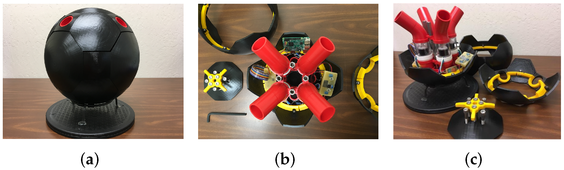
Of particular interest to our work with the RAATM is its potential integration with the Wreck Interior Exploration Vehicle (WIEVLE) AUV [
4]. The WIEVLE is a spherical AUV designed to operate in highly complex environments such as littoral zones, inside shipwrecks, and other environments with a high risk of entanglement. To maximize utility in a variety of mission capacities that require a long loitering time in a specific operating area, an anchor system is sought. Furthermore, periodic communication between the WIEVLE and command and control (C2) infrastructure would expand mission capability while loitering in a given operating area. Thus, the RAATM may be useful to expand the range of missions that the WIEVLE and similar AUVs can perform successfully.
3. Materials and Methods
3.1. Overview
The RAATM is designed to enable a small, lightweight AUV (and specifically the WIEVLE) to secure itself temporarily to the seabed, change depth by paying out and retracting the tether via an internal spool, transmit and receive electromagnetic signals over short distances, re-stow the anchor, and maneuver to another area to repeat the process as required. The mechanism is ideally suited to lightweight vehicles that need to maintain a smooth exterior to reduce drag or entanglement hazards, thus precluding traditional, heavy, external anchoring systems. The key design requirements, therefore, are minimal weight, internal stowability, reusability, and the ability to pay out varying lengths of tether and, thus, change depth without the aid of propulsive thrusters or active buoyancy compensation. The principal means of attachment to the seabed, which presumably consists of sediment, sand, or fine gravel in the operating area, is an anchor “spike”, in the form of an auger, aided by an array of semi-flexible wire “roots” embedded with friction-enhancing bristles surrounding the base of the anchor assembly in a shallow pattern.
The use of a screw-type anchor spike as a principal method of anchoring to the seabed proceeded naturally from the design requirements based on the intended host platform (the SAUV WIEVLE). The chief concern, however, for the use of the anchor spike alone was the risk of failure due to the anchor spike working loose from the sediment due to insufficient gripping strength or the inability to resist angled loads on the tether. A method of enhancing the design’s gripping strength while fitting within the physical boundary constraints of a cylinder (the central space along the WIEVLE’s vertical axis) was sought, and inspiration was taken from the method employed by sea grass to anchor in sand and resist continuously-varying tension loads from wave action—fine roots spread out over a wide surface area. Alternative designs, such as screw-type rigid or semi-flexible “roots” or expanding rigid mechanisms, such as those used to augment certain drywall anchors, were considered but ultimately abandoned due to the complexity of generating the necessary rotation in the case of screw-type anchor branches or the high probability of jamming in the case of folding rigid mechanisms. In both alternatives, a successful deployment seemed likely to be followed by a failed retraction; thus, a simple method of push-pull insertion and retraction was desired to satisfy the reusability requirement.
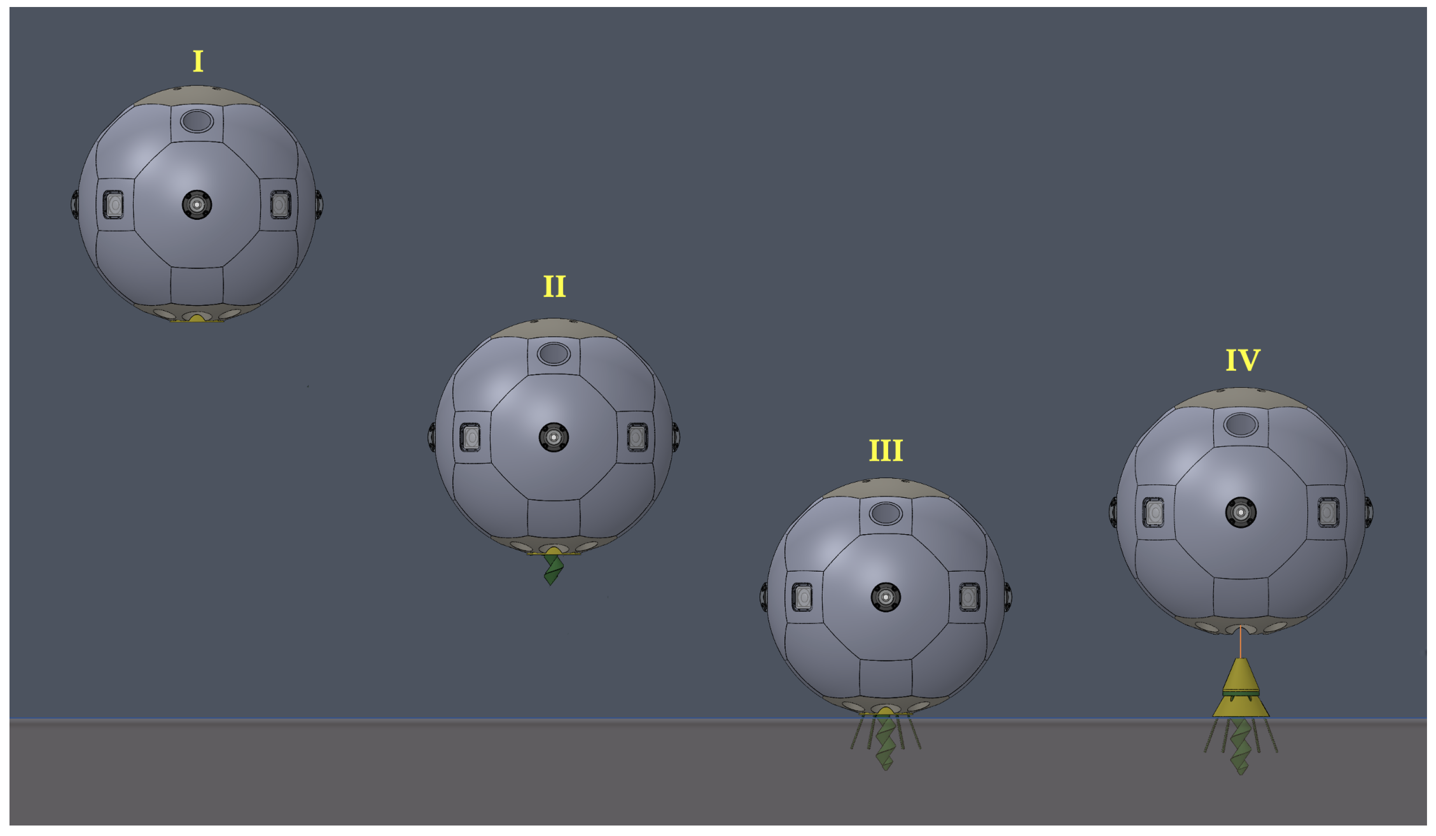
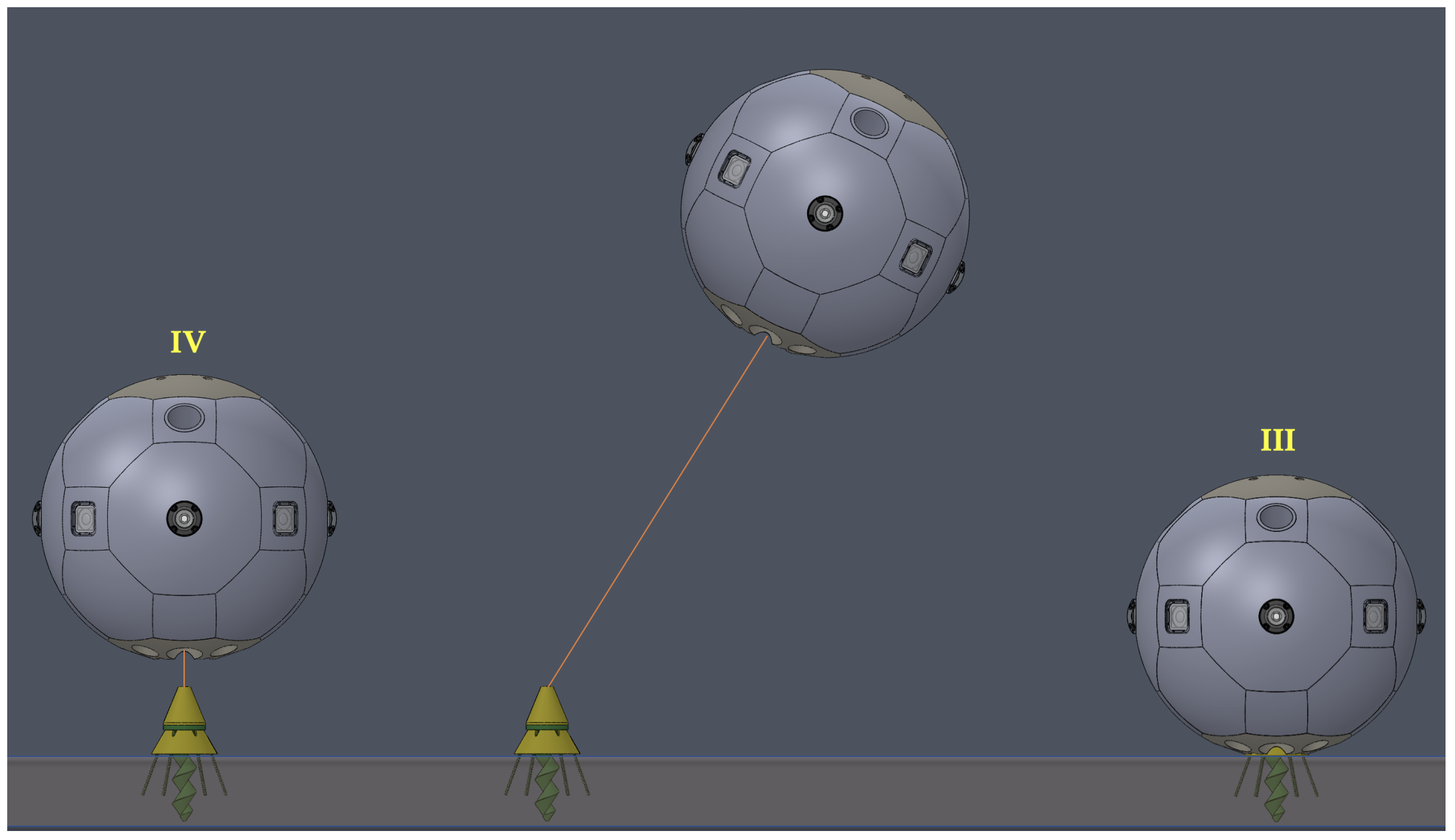
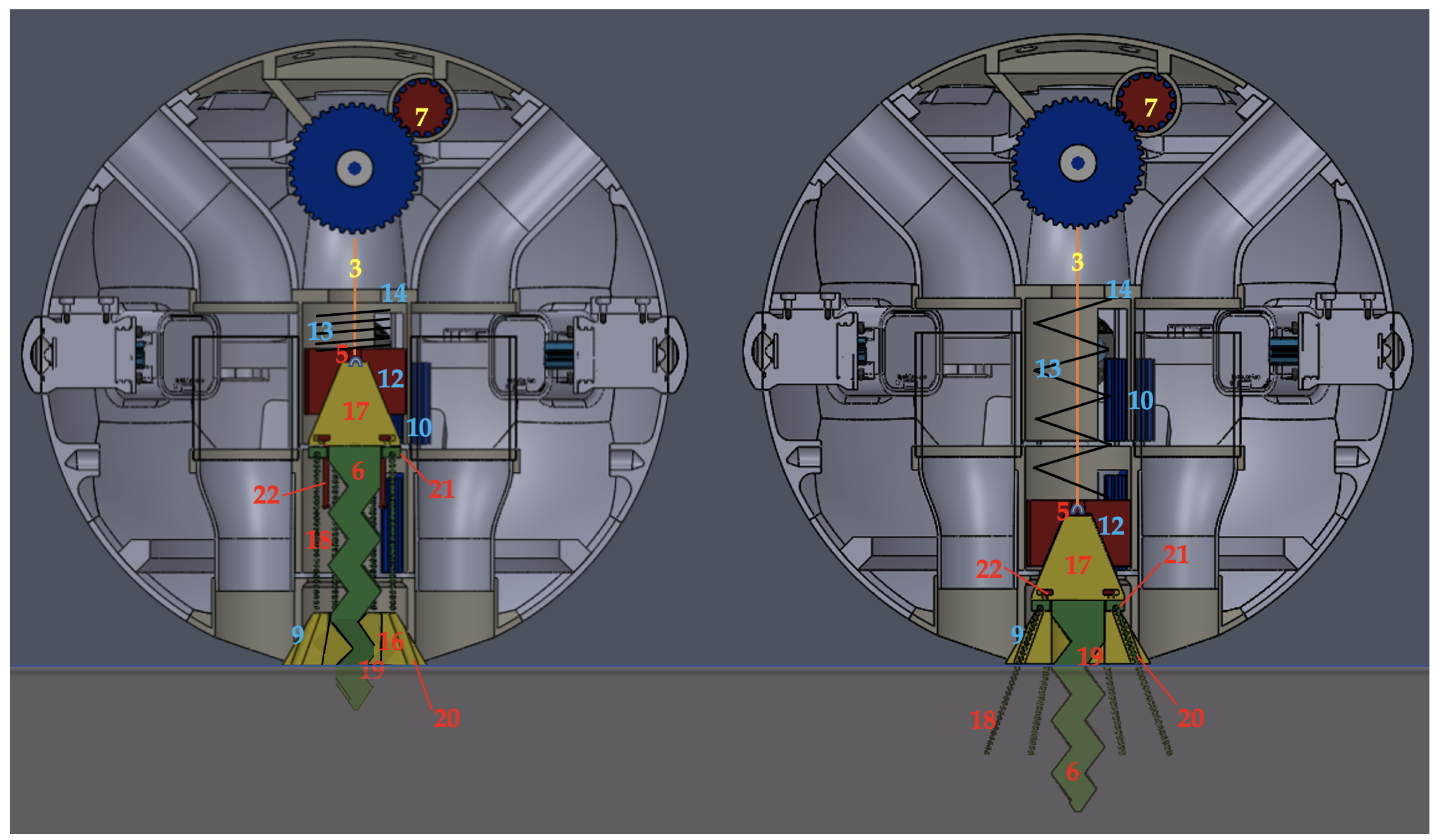
The resulting mechanism operates through four states (I–IV), as depicted in
Figure 2: (I) the
stowed position, (II) the
inject position, (III) the
rooted position, and (IV) the
tethered position. The principal assemblies of the mechanism include the spool and tether assembly, the anchor sleeve assembly, and the retractable anchor assembly, described in detail in
Section 3.2.
3.2. Components
In the following sub-sections, the specific components referenced in the text are numbered for ease of cross-reference with the associated figures, with yellow capital letters denoting vehicle-specific components for reference, yellow numbers denoting spool and tether assembly components, blue numbers denoting anchor sleeve assembly components, and red numbers denoting anchor assembly components. Note that the RAATM was intended to be integrated within a small, spherical AUV, such as the WIEVLE, but could potentially be implemented on a variety of AUVs. In the WIEVLE, the RAATM would be contained within the space aligned vertically with the central axis, also known as the Central Payload Tube (CPT) [
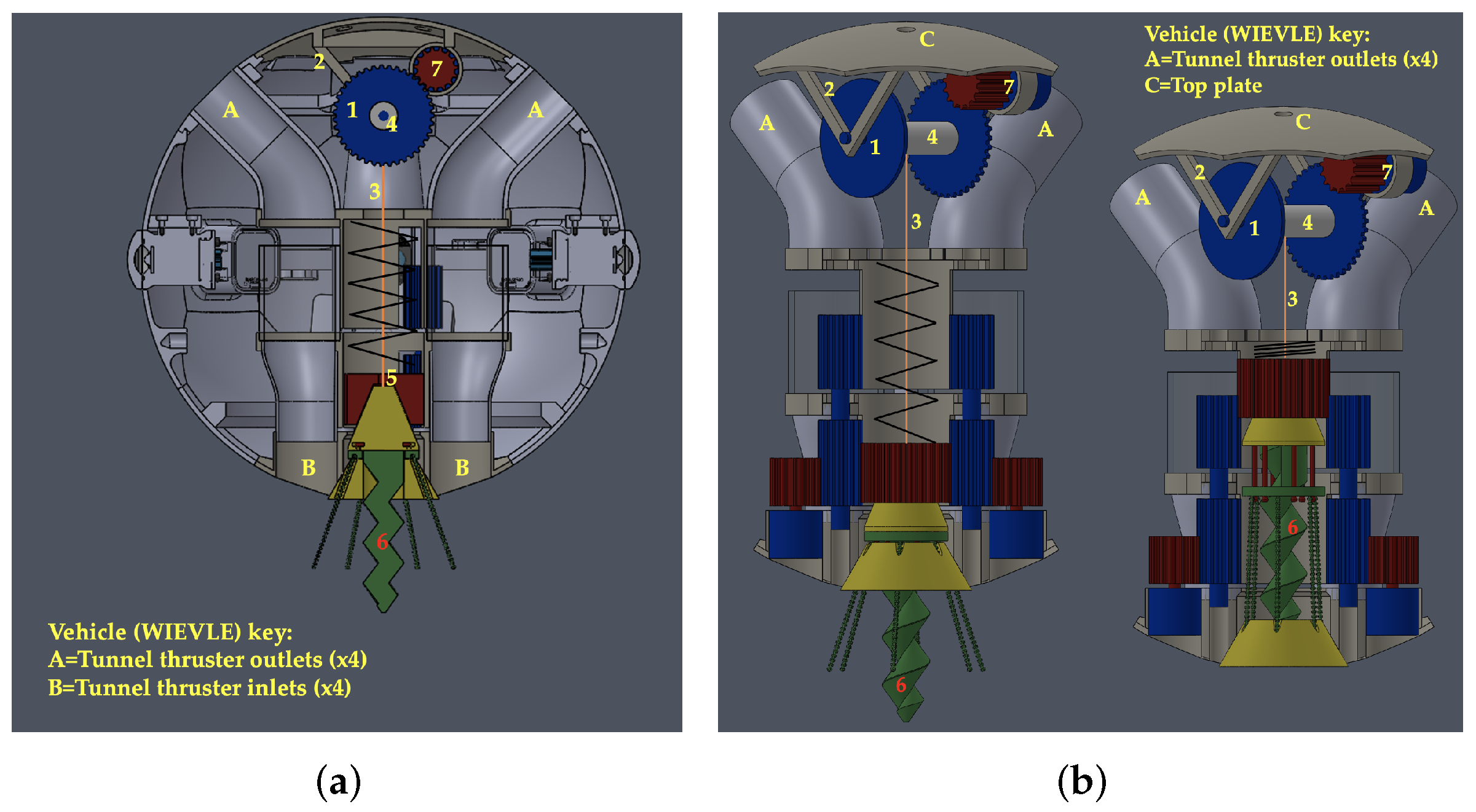
4]. In other underwater vehicles, one or more RAATMs may be incorporated in a similar manner such that the configuration enables the anchor port(s) to directly contact the seabed. The spool and tether assembly components are depicted in
Figure 3 and labeled with yellow numbers.
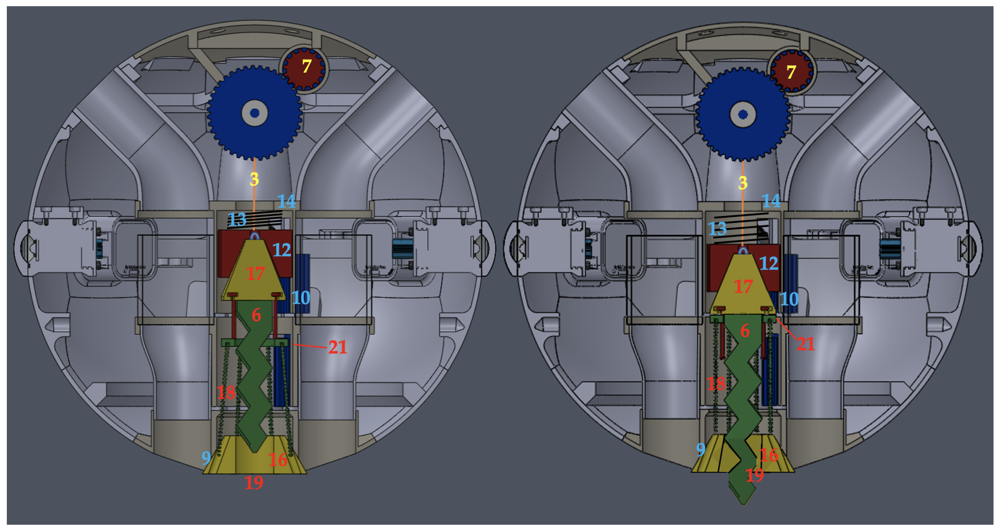
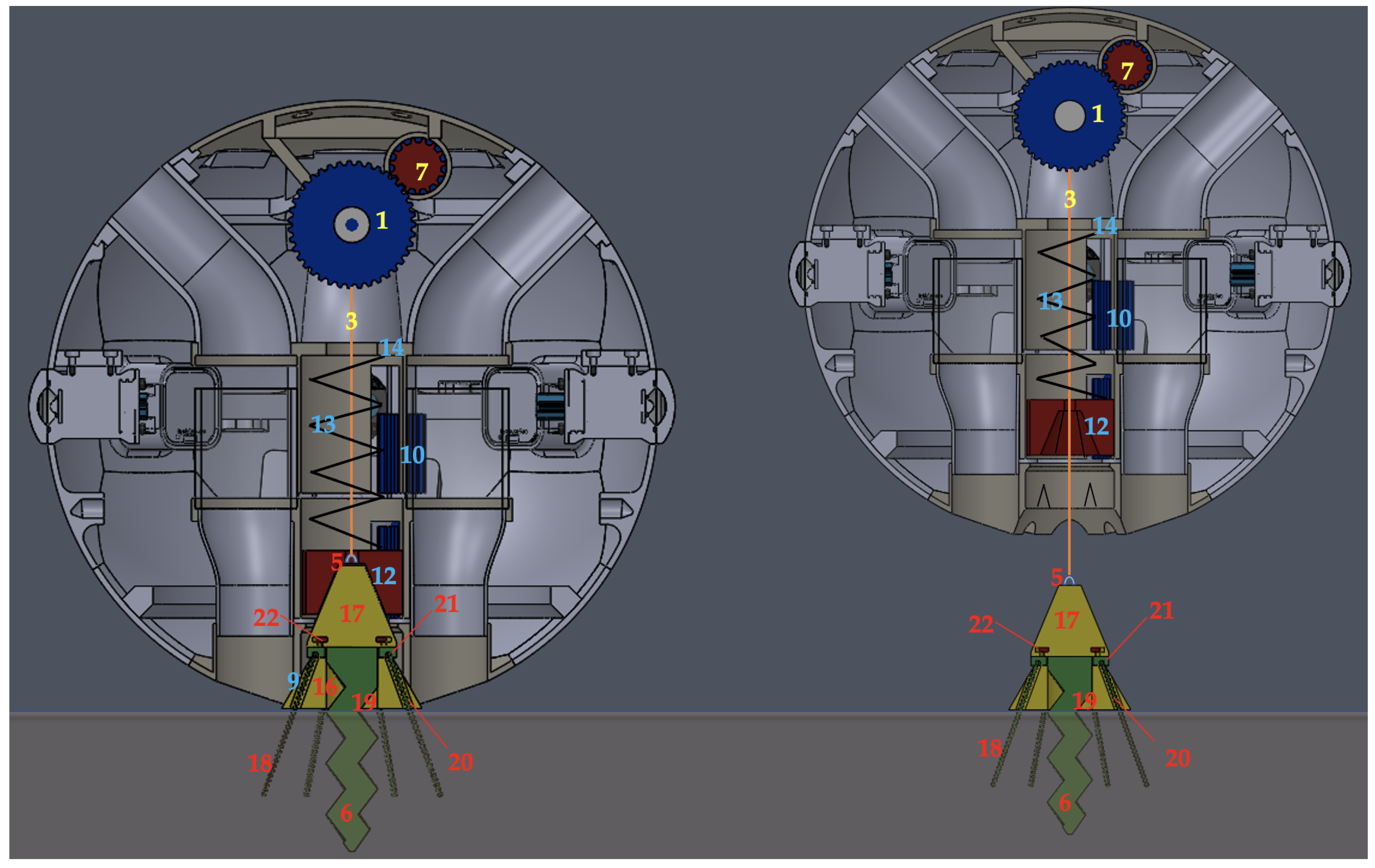
The tether spool (1) is mounted at the top of the mechanism by brackets (2). The tether (3) is connected at one end to the spindle (4), upon which it is wound and through which electromagnetic signals may be sent or received; the tether is connected at the other end to the swivel eyelet (5) at the top of the anchor spike (6). The tether thickness may vary depending on the vehicle’s size, but it should be thin yet strong enough to hold the AUV against anticipated currents. Since the tether also serves as an electromagnetic antenna, the tether and spindle should be made of an appropriately conductive material, and the tether, when deployed, should be extended to a suitable length corresponding to the intended wavelength of the electromagnetic signal to allow signal transmission and reception via the vehicle’s onboard transceiver. Torque is transmitted to the tether spool via one or more electric actuators (7), rotating the spindle to extend or retract the tether. The anchor sleeve assembly components are depicted in
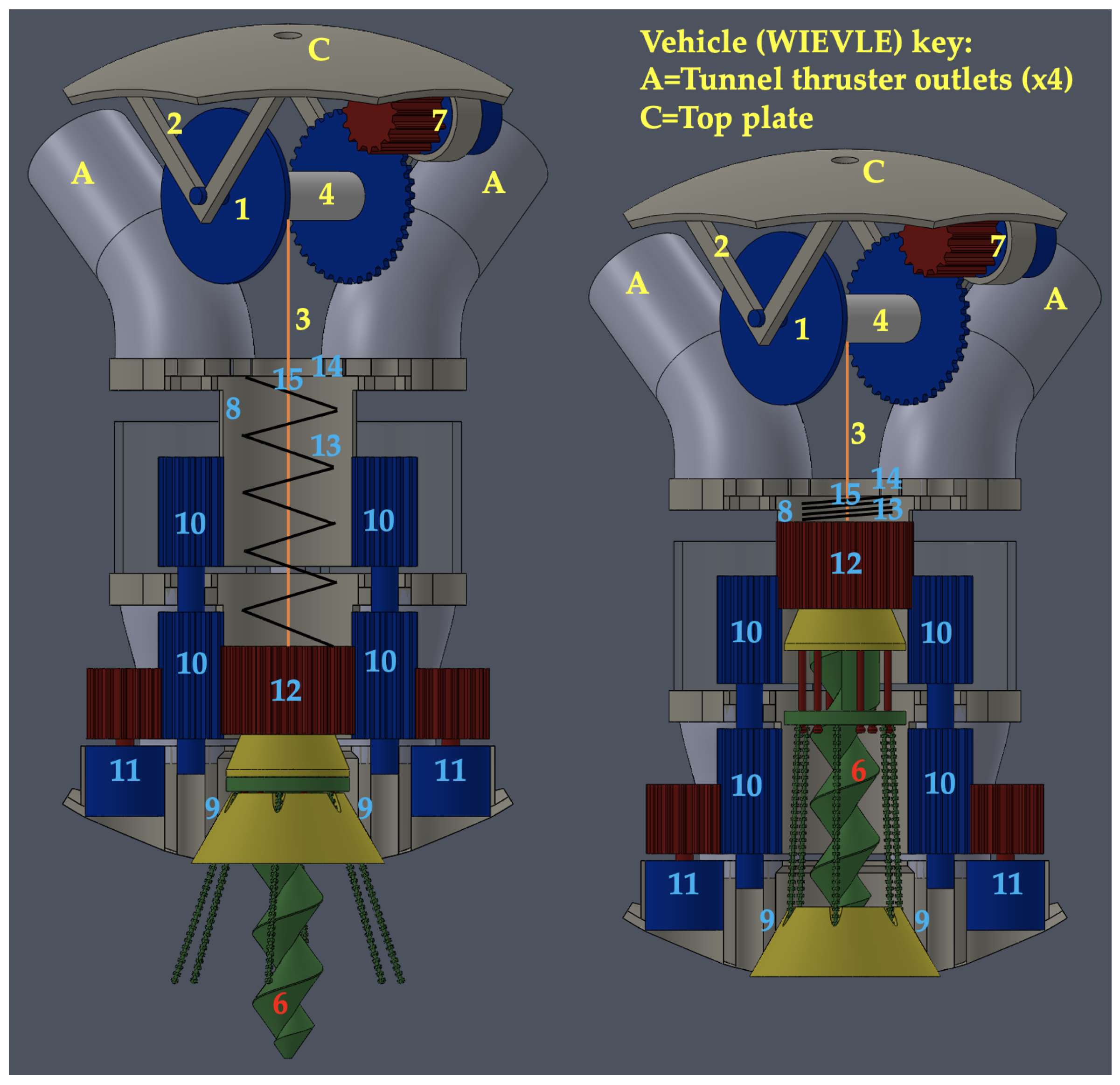
Figure 4 and labeled with blue numbers.
The anchor sleeve (8) is a cylindrical tube positioned below the tether spool (1) that contains the deployable anchor assembly. It consists of a fixed cylindrical tube joined to a beveled, notched anchor port (9) at the base of the hull. The anchor port retains the anchor plug by permanent magnetic inserts in the base of the anchor plug and the anchor port walls. The cylinder extends upward, terminating just below the tether spool (1), and it contains vertical slots that enable the interfacing of corresponding vertical spur gears (10), driven by electric actuators (11) adjacent to the anchor plug, extending upward and engaging with the corresponding outer splines of the anchor cap coupler (12)—a vertically-splined, externally cylindrical and internally conical (concave) spur gear. The anchor cap coupler is compressed by the anchor spring (13) onto a corresponding (convex) conical spur gear that serves as the anchor cap. The anchor cap coupler has a small, beveled, central guide hole allowing the swivel eyelet (5) to insert and the tether (3) to pass through. The anchor spring (13) glides smoothly within a groove at the top of the anchor cap coupler (12) to allow the anchor cap coupler to rotate freely inside the anchor sleeve (8). The anchor sleeve cap (14) is fixed at the top of the anchor sleeve (8) and retains the anchor spring (13) to enable compression. The anchor sleeve cap (14) contains a central guide hole (15), reinforced with a Teflon insert, to resist abrasion from the tether and damage to the tether, reduce friction, and center the tether onto the tether spool (1). The tether spool incorporates a latching mechanism to relieve tension from the spindle actuator (7) in the fully retracted, stowed position.
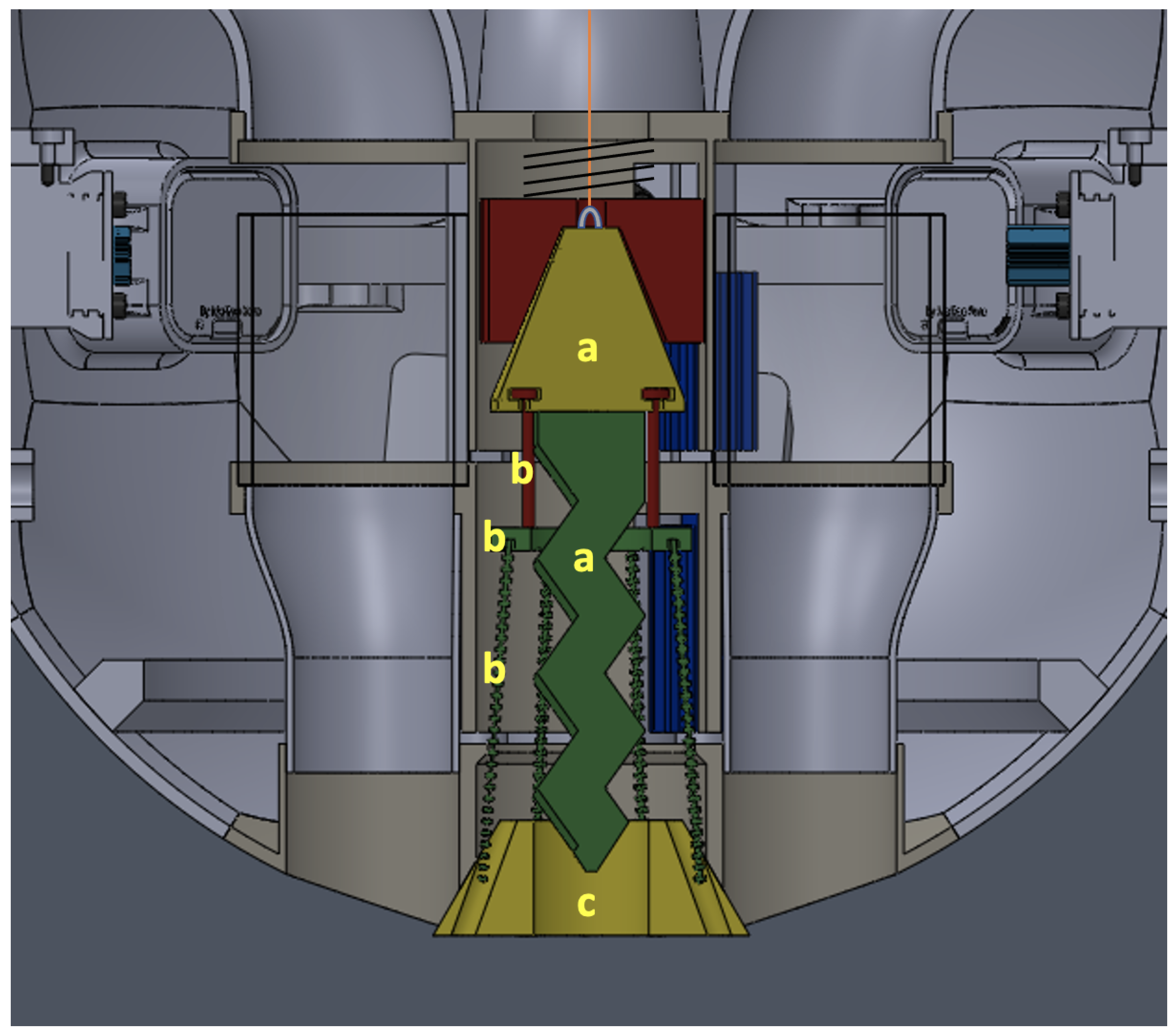
The anchor assembly consists of three sub-assemblies (a–c) as depicted in
Figure 5: (a) the anchor spike sub-assembly, (b) the wire root array sub-assembly, and (c) the anchor plug sub-assembly.
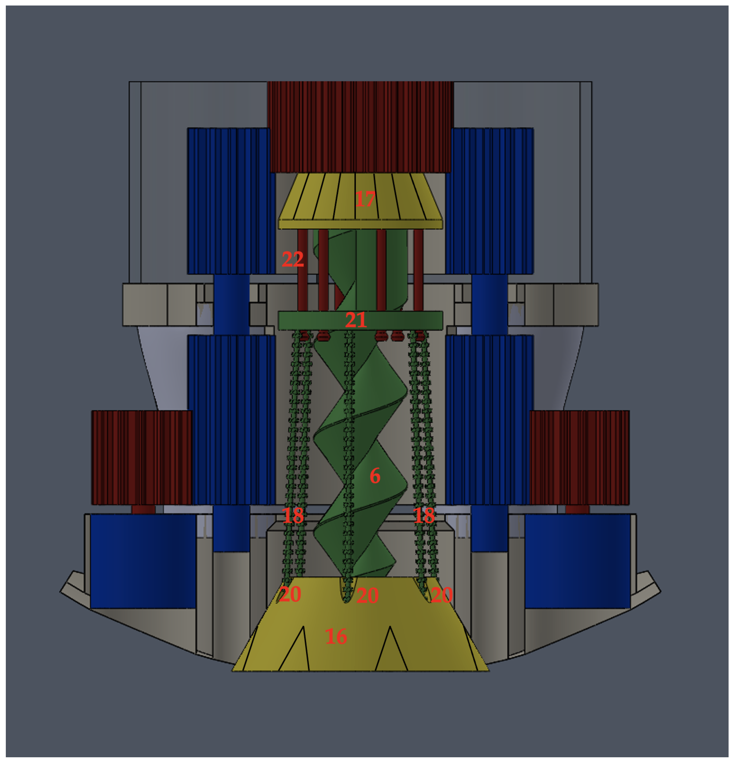
The anchor assembly components are depicted in
Figure 6 and labeled with red numbers.
The anchor plug (16) forms the body of the anchor assembly and retains the anchor cap (17), with its embedded anchor spike (6), and the wire root array (18). It is seated at the base of the anchor sleeve (8) inside the beveled anchor port (9), and it is held in position by rare-earth (permanent) magnets (not depicted). Vertical splines (aa) on the anchor plug exterior align with corresponding beveled, vertical slots (ab) in the anchor port (9) to resist rotation during anchor cap (17) rotation. These grooves help guide and re-seat the anchor plug in position during the retraction of the tether. The anchor plug (16) and anchor cap (17) are made of Teflon to reduce fouling and minimize friction during the re-seating of the anchor plug into the anchor port, the passage of the anchor spike through the spike well (19), and the passage of the wire root array (18) through the root tunnels (20) in the anchor plug.
The outer surface of the head of the anchor cap is ribbed with vertical splines (bb) that mate with the corresponding splines (bc) of the concave interior surface of the anchor cap coupler, thereby enabling the anchor cap coupler to transmit torque to and rotate the anchor cap (17). The anchor spike (6) is rigidly affixed to the anchor cap and is ideally made of a material such as stainless steel to provide weight and add resilience. Thus, the anchor cap retains the anchor plug and provides a mounting point for the swivel eyelet (5). The anchor tether is connected to the anchor spike via a free-spinning swivel eyelet (5) that enables the anchor spike to rotate without winding the tether. The anchor spike is shaped like an auger, and it passes through correspondingly shaped spike well (19) to enable the contraction of the anchor assembly while also serving as the primary means of attachment of the anchor assembly to the seabed. The wire root array sub-assembly (b) is depicted in
Figure 7.
The anchor spike passes through a non-rotating, rigid metal washer known as the wire root ring (21), which joins the wire brush anchor roots into an array (18). The wire root array consists of a set of thin, flexible, stiff wire brushes with interwoven synthetic bristles made of a corrosion-resistant metal, such as braided stainless steel. Each brush passes through a corresponding root tunnel (20) within the anchor plug (16), which angles gradually outward from the vertical axis. The wire root ring (21) and wire root array (18) are stationary with respect to the anchor plug (16) as the anchor cap (17) and spike (6) are rotated, and are held in this position by the wire root array, which is fixed within the root tunnels of the anchor plug, as well as a set of root ring retention rods (22). The purpose of the retention rods (22) is to delay the injection of the wire roots until the anchor spike has been extended a preset depth into the seabed and then retract the wire root array during the retraction of the anchor by pulling up on the root ring (21). The retention rods should be free to move within a lipped groove set in the lower face of the anchor cap (17), which provides retention to the upper ends of the rods. The retention rods pass freely through the root ring (21) and into corresponding vertical retention rod tunnels (23) within the anchor plug in the rooted position. The lower ends of the rods are capped such that the rods (22) may freely extend into the anchor plug during the seating of the anchor cap onto the anchor plug, but retain the root ring (21) as the anchor spike is unscrewed into the fully retracted position, thus pulling the array out of the sediment and back into the root tunnels (20) of the anchor plug.
3.3. Sequence of Events
3.3.1. Stowed to Inject Position
In the
stowed position, depicted in
Figure 7 and phase I of
Figure 2, the anchor assembly is completely enclosed within the anchor sleeve, the anchor spike is fully retracted, the anchor plug is flush with the bottom of the hull, and the AUV may maneuver normally, free of external protrusions. At the start of the anchoring sequence, the anchor spike (6) is extended through the spike well (19) at the bottom of the anchor plug (16) into the
inject position, as depicted in phase II of
Figure 2, while the vehicle descends. An internal view of this phase transition is depicted in
Figure 8.
The protrusion of the anchor spike (6) enables the vehicle to leverage downward momentum to aid in the penetration of the seabed surface while simultaneously lowering the vehicle’s center of gravity slightly and promoting a vertical orientation due to the increased righting moment caused by the increased vertical separation of the center of gravity from the center of buoyancy. The increased righting moment is especially helpful in the case of spherical AUVs, as proper vertical orientation further ensures that the bottom of the sphere will come into contact with the seabed first, and the anchor spike will be driven into the sediment more efficiently.
To position the anchor spike (6) into the inject position, the tether spool actuator (7) briefly tensions the tether (3), compressing the anchor spring (13) and releasing the tensioner latch; it then reverses to allow the spool to unwind freely and enable the anchor spring to expand against the anchor sleeve cap (14) and compress the anchor cap coupler (12) firmly onto the anchor cap (17). The vertical spur gear gears (10) are then rotated via electrical actuators adjacent to the anchor plug (16). The vertical spur gears (10) interface with the vertical outer splines of the anchor cap coupler (12) through slots in the anchor sleeve. The outer splines of the anchor cap coupler slide freely along the vertical spur gears as they rotate, transferring torque to the anchor cap (17) and spike (6), which rotates and extends the spike through the spike well (19). As the anchor spike is extended out the bottom of the anchor plug, the lower face of the anchor cap (17) contacts the wire root ring (21), causing it to be in position to be compressed by the anchor cap (17) when the anchor spike (6) is screwed further into the anchor plug (16) during the next phase of deployment. The anchor spike (6) is held in position by corresponding inner “threads” (not depicted) of the spike well (19) semi-rigidly, enabling sufficient resistance for impact and penetration of the surface of the seabed during the inject phase, while the wire root array (18) remains retracted within the anchor plug (16).
3.3.2. Inject to Rooted Position
As depicted in phases II–III of
Figure 2, the vehicle descends in the
inject position until it firmly drives the protruding anchor spike tip into the sediment, thus initiating the
rooting phase of operation. An internal view of the
inject to
rooted phase transition is depicted in
Figure 9.
Upon contact with the seabed, the anchor spike (6) is rotated further through the anchor plug (16), driving the anchor spike deeper into the sediment. To counter the reaction torque on the vehicle during augering, the vehicle must command an opposite yaw while maintaining downward force until the anchor cap (17) is fully seated in the anchor plug (16), unless the vehicle’s weight or use external structure is sufficient to resist this torque.
As the anchor cap (17) is rotated, the spike extends further through the anchor plug (16) and deeper into the sediment. The swivel eyelet (5) at the top of the anchor spike prevents the tether (3) from twisting. The anchor cap (17) presses down on the wire root ring (21), freely rotating over the non-rotating ring and forcing the wire root array (18) through the root tunnels (20) as the root ring retention rods (22) drive into their corresponding wells within the anchor plug (16). The wire root bristles are driven into the sediment around the base of the anchor plug. When the anchor cap coupler (12) reaches the aft stops within the anchor sleeve, the anchor assembly is fully rooted.
3.3.3. Rooted to Tethered Position
Once the anchor cap coupler (12) reaches the aft stop, counter-torque yaw and downward thrust is ceased, and a brief upward thrust may be commanded to unseat the anchor plug (16) as the tether spool (1) is allowed to rotate freely. If the anchor assembly holds fast to the sediment, the anchor plug is pulled free from its magnetic coupling and the vehicle ascends away from the anchor assembly into the
tethered position, as depicted in phase IV of
Figure 2. An internal view of the transition from the
rooted to
tethered positions is depicted in
Figure 10.
If the AUV is sufficiently buoyant, the vehicle may be able to ascend passively above the anchor assembly. Tether length can be adjusted as required for control of depth or antenna length by rotating the tether spool (1) to shorten or lengthen the tether (3), as depicted in
Figure 11.
3.3.4. Retraction
To retract the anchor and continue propagation, the AUV executes the reverse of the anchoring sequence. First, the spool actuator (7) rotates the tether spool (1) and winds the anchor tether (3) back onto the spool, reeling the vehicle back in toward the anchor assembly. The central guide hole in the anchor cap coupler (12) helps center and guide the anchor port (9) over the top of the anchor assembly as the final length of tether is retracted. When the anchor assembly contacts the anchor port, the beveled grooves (see ab of
Figure 6) of the anchor port (9) guide the anchor plug splines (aa) into position, and the plug (16) continues to seat. As the anchor plug nears the fully seated position, the magnets within the anchor port (9) and anchor plug pull the anchor plug firmly into the seated position, and the slack of the tether (3) is taken up by the tether spool (1). The vehicle has now returned to the
rooted position (phase III of
Figure 11), and the vertical spur gears (10) engage the anchor cap coupler (12), loosening the anchor spike (6) through the anchor plug (16) and retracting it from the sediment. The anchor spring (13), still under compression, maintains the necessary downward force on the anchor cap coupler (12) to ensure coupling with the anchor cap (17). The loosening anchor cap continues to rise, passing through the
inject position, until the lower caps of the root ring retention rods (22) contact the lower side of the wire root ring (21) and begin to pull the wire root ring upward, retracting the wire roots (18) back into the root tunnels (20). When the anchor spike (8) is fully retracted into the anchor plug (16), the anchor spring (13) is once again fully compressed, and the tether spool (1) can then be further rotated until the tensioner latch engages. The mechanism has then returned to the
stowed position, and the vehicle is free to maneuver and repeat the process again as required.
3.4. Design of Experiments
Several experiments were developed to gain insight into the performance potential of the RAATM’s anchoring function (anchoring strength) and the influence of the wire root array on anchoring strength by assessing the capability of the anchoring portion only (the wire roots and anchor spike components of the anchor assembly) to hold fast in various sediments when under tension. Toward this end, the authors sought to answer three primary research questions:
- (1)
What effect does sediment type have on anchoring strength?
- (2)
What effect does increasing the number of wire roots in the array have on anchoring strength?
- (3)
What effect does combining the wire root array with the anchor spike have on the mechanism’s ability to resist angled loads?
An experiment was designed for each research question, and a simple prototype of the lower portion of the anchor assembly (a partial anchor plug, an anchor spike, and a wire root array) was constructed. The construction of this prototype is discussed in
Section 3.5. Three distinct types of sediments were collected from the local environment to test the anchoring strength of the assembly. The goal was to achieve the best possible representative sampling of possible seabed conditions (capable of penetration). The collection of sediments used is discussed in
Section 3.6. The procedure for each experiment is discussed in
Section 3.7, and the results are discussed in
Section 4.
The first experiment was designed to answer the first research question by collecting data samples for anchor line tension (force) at the point of uprooting (hereafter referred to as anchoring strength) using the prototype. To test the correlation between sediment type and anchor strength, three distinct types of sediments with differing particle sizes were collected, with the prediction that smaller-particle-size sediment conditions would yield higher anchoring strength. The experimental null hypothesis, therefore, was that sediment type has no effect on anchoring strength. Three data cells consisting of 30 individual tests of anchor strength (hereafter referred to as “pulls”) were collected for each of the three sediment conditions in Test 1 for comparative statistical analysis.
The second experiment was designed to answer the second research question by collecting anchoring strength data for the three sediment conditions using three configurations, under vertical loads, in order to understand the relative contribution of the number of wire roots in the array to the overall anchoring strength. The full array of eight wire roots was used for Test 1 of the first experiment. A partial array of four wire roots (Test 2) and no array at all (Test 3) were used for data collection in Experiment 2. The experimental null hypotheses were: the mean anchoring strength for each configuration is equal (H01), the mean anchoring strength for each condition is equal (H02), and there are no interactions between the factors (H03). Thus, nine data cells consisting of 30 pulls each were collected in Tests 1–3 for comparative statistical analysis.
Finally, the third experiment was designed to answer the third question by collecting anchoring strength data for the three sediment conditions using two anchor configurations—the full array of eight wire roots (Test 4) and no array at all (Test 5)—under angled loads, in order to understand the contribution of the full wire root array to resisting angled loads. The prediction was that the wire root array would aid the mechanism in resisting angled loads, with the corresponding null hypothesis that the wire root array would have no effect on resisting angled loads. Due to time and logistics constraints, ten pulls were conducted for each condition and configuration. The collected data were sufficient, however, for the comparative statistical analysis.
3.5. Construction
The constructed prototype, depicted in
Figure 12, is very close to the correct dimensions for use within the WIEVLE’s CPT.
For the purpose of the experiments, the authors were only concerned with the portion of the anchor assembly that penetrates the sediment and the method of insertion for each penetrating component. The test prototype, depicted in
Figure 12, was constructed from readily-available commercial materials and designed to allow the wire root array to be pushed into the sediment around the anchor spike, which was then augured into the sediment. The prototype consists of a green plastic anchor spike, a black wooden anchor plug, acrylic spacers, eight wire roots made from bottle brushes, and a wire root ring made from a steel flat washer.
The anchor spike is a common screw-type “beach anchor”. This commercial product has smooth, rounded, tapered threads spaced approximately 1.9 cm per turn and 0.952 cm deep. The spike also narrows slightly overall along its length and measures approximately 1.9 cm in diameter along the 10.16 cm that insert into the sediment. It differs from the proposed mechanism primarily in material, being made of lightweight plastic instead of solid stainless steel that would have the added anchoring benefits of weight and durability.
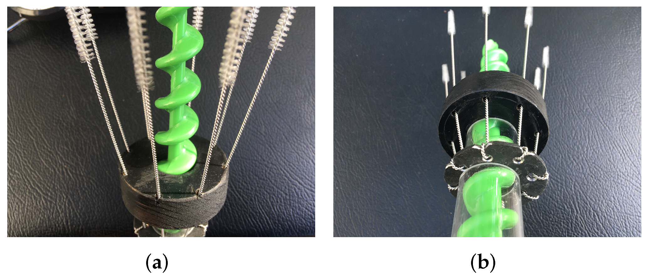
The wire root array, depicted in
Figure 13, was assembled from eight 19.05 cm long 304 stainless steel braided wire pipe cleaners with nylon bristles 2.5 mm in length covering the last 3.175 cm of each brush.
The wire root ring was constructed from a 1.59 cm diameter steel flat washer. Eight holes were punched through the metal, and corresponding notches were cut along the outer edge to allow the braided wire to be secured yet free to rotate slightly as the array is inserted and retracted through the anchor plug. This wire root array is very similar to the proposed mechanism.
The anchor plug was constructed from a pine wood disk 5.715 cm in diameter, 1.9 cm thick with a 2.22 cm diameter central hole. Eight holes (root tunnels) for the wire brushes were drilled symmetrically at a slight angle along the perimeter. The angled root tunnels allow the wire roots to spread out conically into the sediment around the anchor spike as the ring is depressed. The wooden plug was painted to reduce water damage during testing. It differs somewhat from the proposed mechanism in both shape and material, yet it allows the required movements of the anchor spike and wire root array for testing purposes while providing sufficient support.
The plastic augers were sold with tight-fitting acrylic tubing for storage, which was cut and used to create spacers to ensure consistent deployment of the assembly into the testing sediment. A 2.54 cm spacer between the wire root ring and the anchor plug ensures the wire assembly is fully inserted by depressing the ring down until contact is made between the wire ring, the spacer, and the plug. A 5.4 cm spacer above the wire ring is used to ensure the plastic anchor spike is fully rotated into the sediment until contact is made between the thumb ring at the top of the spike, the spacer, and the wire ring (washer). Thus, when the assembly is fully inserted and all components are fully seated, a consistent 9.21 cm of wire roots and 10.16 cm of anchor spike is extended into the sediment.
3.6. Sediment Samples
Three types of sediment were collected to simulate potential seabed environments, as depicted in
Figure 14.
The first sample (condition 1), depicted in
Figure 14a, consists of a mixture of clay and asphalt pebbles collected along a rural road in Monterey, California. The second sample (condition 2), depicted in
Figure 14b, consists of fine, dark silt collected from the Monterey hillside to simulate river bottoms, freshwater lakebed sediments, or river silt deposits in littoral regions. The third sample (condition 3), depicted in
Figure 14c, consists of actual beach sand collected from Monterey Bay. Typical sediment particle sizes for clay, silt, and sand are generally <0.002 mm, 0.002–0.05 mm, and 0.05–2 mm, respectively [
37,
38]. The samples were collected in five-gallon buckets approximately 26.5 cm in diameter and filled to approximately equal depths sufficient for full rooting of the prototype. Fresh water was then added until a depth of approximately 10cm above the fully saturated sediments was achieved. The buckets were then disturbed to help release trapped air bubbles and allowed to settle until off-gassing was observed to cease (for at least an hour) prior to testing.
3.7. Procedure
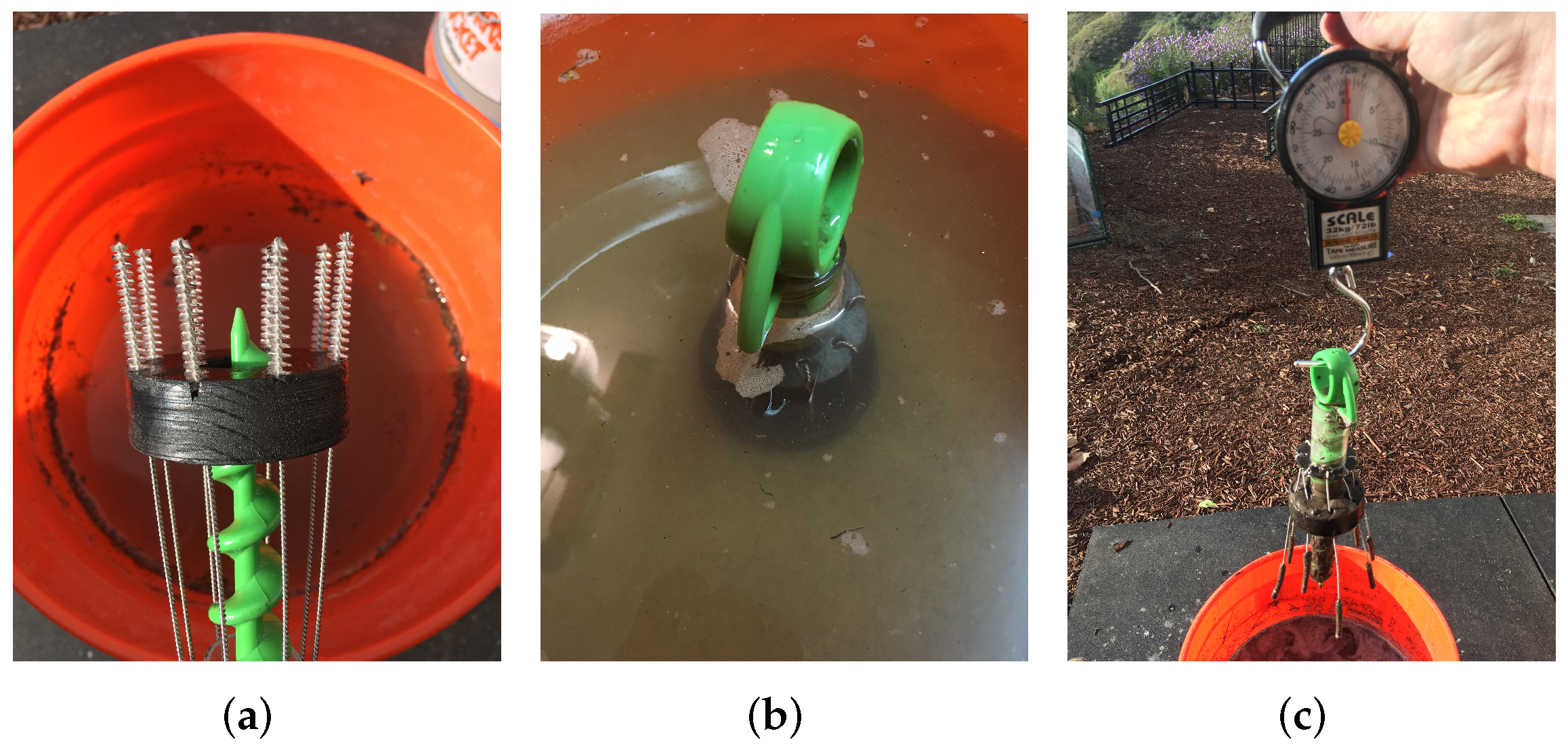
The testing sequence is depicted in
Figure 15.
A hand-held scale with a max weight indicator was checked for calibration and used to measure anchoring strength. During each pull, the wire root array was carefully inserted into the sediment and the root ring was depressed until it fully compressed the acrylic spacer onto the anchor plug resting on the sediment. Care was taken not to allow the plug itself to depress more than approximately 1cm into the sediment or the wire roots to jam, tangle or otherwise fail to insert through the root tunnels in the anchor plug. The spike was then inserted through the wire root ring and anchor plug and carefully screwed into the sediment until firmly compressed against the upper spacer. The scale hook was then inserted through the thumb ring at the top of the plastic anchor spike, and the handle was smoothly pulled upward for the vertical tests, or at an approximately 45-degree angle for the angled tests, until the anchor released from the sediment. The angle was kept consistent for the angled pulls by keeping the scale handle just above the upper lip of the bucket during the pull, set to equal heights in all three sediment conditions, with the anchor rooted to the same depth and the scale attached at the same point (the thumb ring of the anchor spike). Care was taken to pull steadily without jerking the anchor free. The force was smoothly yet reasonably swiftly applied over a relatively short time period (approximately 1–2 s)—not as a jerk. The objective was to produce a consistent, steady pull through failure. We believe a jerk would give an unduly high strength measurement for the pulls. It is, however, worth noting that it is likely that in real-world scenarios, jerk force applications could influence anchoring strength. Such scenarios could reasonably be expected in shallow littorals affected by wave action, for example. Jerk force testing was outside the scope of testing for this early prototype analysis. Following the pull, the max tension (in pounds) was recorded. To prepare for the next pull, sediment was removed from the assembly, and a wooden block was used to firmly re-compact the sediment. The bucket was then rotated slightly so as to avoid using the exact same spot for the subsequent pull and help ensure the independence of the data.
Test 1 consisted of a sample of 30 straight (vertical) pulls using the full array of eight wire roots within the anchor plug and the spike fully inserted in each of the three sediments, for a total of 90 pulls. Test 2 was conducted in a similar manner, with the exception of the reduction in the total number of wire roots within the array to four, evenly spaced, again for a total of 90 pulls. Test 3 consisted of the same procedure, but with the anchor spike alone, inserted to the same depth as in all the other tests, once again for 90 pulls. Test 4 consisted of ten pulls in each of the three sediment types using the full wire root array (eight wires) but this time pulling at an angle of approximately 45 degrees, for a total of 30 pulls. Test 5 was conducted in the same manner as Test 4 but without the wire root array (anchor spike only), again for a total of 30 pulls.
5. Discussion
5.1. Experiment 1
The clay/pebble mixture (condition 1) and fine silt (condition 2), once sufficiently settled, produced very similar mean anchoring strengths of 16.9 lbf and 16.1 lbf, respectively. Beach sand, however, produced a mean anchoring strength of only 4.3 lbf, or approximately 25% of that of the first two conditions. A one-way, single-factor analysis of variance (ANOVA) was conducted comparing the anchor strength data for the three sediment conditions collected in Test 1 with a significance level of 0.05, with a resulting f-value of 162.222 that exceeded the f-critical value of 3.101 and a p-value of 4.431 × 10. Thus, we conclude that the influence of sediment condition on mean anchoring strength is significant, with a 95% confidence level. The variances for conditions 1, 2, and 3 (14.81 lbf, 11.94 lbf, and 1.07 lbf, respectively) demonstrate a likelihood of unequal population variances, however. Thus, three two-sample t-tests (two-tailed) were conducted, assuming unequal variances at a significance level of 0.05, to confirm which groups had significantly differing means.
The first t-test compared the anchoring strength data for conditions 1 and 2, with a resulting t-statistic of 0.851 and a p-value of 0.398; therefore, we conclude that a significant difference does not exist between the mean anchor strength for condition 1 vs. condition 2. The second t-test compared the anchoring strength data for conditions 2 and 3, with a resulting t-statistic of 17.985 and a p-value of 6.076 × 10; thus, we conclude that a significant difference does exist between the mean anchor strength for condition 2 vs. condition 3. Finally, the t-test comparing the anchoring strength data for conditions 1 and 3, with a resulting t-statistic of 17.381 and a p-value of 3.552 × 10, allows us to conclude that a significant difference does exist between the mean anchor strength for condition 1 vs. condition 3.
As predicted, the Experiment 1 analysis confirmed, at a 95% confidence level, that sediment type does have a significant influence on anchoring strength, but only between condition 3 (sand) and the other two conditions (clay/pebble mixture and silt). No significant difference in mean anchoring strength exists between clay/pebble mixture and silt.
5.2. Experiment 2
The effect of the number of wire roots on anchoring strength was somewhat surprising, with Test 2, utilizing a partial array, producing unexpectedly high mean anchoring strengths. Test 2, configured with a four-root partial array, produced mean anchoring strengths for sediment conditions 1–3 of 19.3 lbf, 30.9 lbf, and 3.9 lbf, respectively. Test 3, configured with the anchor spike only, produced mean anchoring strengths for conditions 1–3 of 15.3 lbf, 15.9 lbf, and 2.0 lbf, respectively.
A two-factor ANOVA with replication was conducted. The first null hypothesis (that the mean anchoring strengths for each configuration are equal) is rejected with an f-value of 96.928, an f-critical value of 3.03, and a p-value of 3.30 × 10. The second null hypothesis (that the mean anchor failure tensions for each sediment condition are equal) is rejected again, as it was in Experiment 1, with an f-value of 611.065, an f-critical value of 3.03, and a p-value of 3.41 × 10. Finally, the third null hypothesis (that there are no interactions between the factors) is rejected with an f-value of 45.679, an f-critical value of 2.406, and a p-value of 4.59 × 10.
As expected per our hypothesis, the average anchoring strength for condition 3 (beach sand) decreases from a full array, to a partial array, to none. In conditions 1 and 2, however, the partial array produced much higher anchoring strength than the full array. Two potential explanations for this unexpected result are offered. First, due to a several-day-long delay in testing between Tests 1 and 3 (the full array and no array, respectively) and Test 2 (the partial array), continued settling and firming were observed for conditions 1 and 2. For efficiency, the full-array tests were conducted first before removing four of the roots to conduct the partial array tests. Settling time, combined with decreasing ambient air temperatures, may have caused stiffening of the clay and silt samples, leading to higher anchor failure tensions. The beach sand, by contrast, being very homogeneous and stable, provided a more reliable test environment, and the resulting mean anchoring strengths behaved according to our hypothesis. Second, the wire roots, when in the partial array configuration, were prone to tangling during injection, leading frequently to a snarled deployment within the clay and silt samples. This, especially when combined with firmer sediment, may have contributed to the higher anchoring strengths. Such behavior, although more effective at holding fast, could be catastrophic in an actual deployment because it might prevent the successful retraction of the array. It is recommended that those seeking to replicate this experiment ensure sample equilibrium before collecting test data by conducting standardized pulls at regularly-spaced time intervals until a consistent anchoring strength is achieved for a particular sediment sample.
To determine whether the presence of the complete array contributed significantly to anchoring strength under vertical loads, a two-sample t-test, assuming unequal variances and with a significance level of 0.05, was conducted to compare the data from Test 1 (full array) with those of Test 3 (spike only) for each sediment condition. Three two-sample t-tests, assuming unequal variances, were conducted comparing the anchoring strength data for conditions 1–3 of Tests 1 and 3, with a significance level of 0.05. The first t-test, comparing condition 1 samples, resulted in a t-statistic of 1.784 and a two-tailed p-value of 0.08. The second t-test, comparing condition 2 samples, resulted in a t-statistic of 0.219 and a two-tailed p-value of 0.828. The third t-test, comparing condition 1 samples, resulted in a t-statistic of 11.563 and a two-tailed p-value of 1.662 × 10. Thus, we conclude that a significant difference does not exist between the mean anchoring strengths of the mechanism with the full wire root array vs. without the array for sediment conditions 1 and 2, but does exist for condition 3, at a 95% confidence level.
In summary, the Experiment 2 analysis confirmed, at the 95% confidence level, that both sediment condition and wire root array configuration do have a significant influence on anchoring strength (with significant interactions) under vertical loading; specifically, it was found that the complete array significantly increases anchoring strength under vertical loads in sand (with larger particle sizes) but not in clay or silt (with smaller particle sizes).
5.3. Experiment 3
Tests 4 and 5 produced anchoring strength data under angled loading of the type that would be experienced in a current pushing the tethered AUV some lateral distance away from the anchor plug (as depicted in
Figure 11), thus enabling analysis in support of question 3. The wire root array was specifically designed to address this situation; thus, the hypothesis was that the array would aid in anchoring strength. Experiment 3 testing consisted of ten angled pulls for each sediment condition, for a total of 30 pulls, for both configurations. Test 4, which was conducted using the full wire root array, produced mean anchoring strengths for conditions 1–3 of 21.9 lbf, 22.5 lbf, and 3.2 lbf, respectively. Test 5, which was conducted without the wire root array, provided average failure tensions of 15.5 lbf, 12.1 lbf, and 1.2 lbf, respectively.
Three two-sample t-tests, assuming unequal variances, were conducted comparing the anchoring strength data for conditions 1–3 of Tests 4 and 5, with a significance level of 0.05. The first t-test, comparing condition 1 samples, resulted in a t-statistic of 3.365 and a two-tailed p-value of 0.00345. The second t-test, comparing condition 2 samples, resulted in a t-statistic of 7.841 and a two-tailed p-value of 2.786 × 10. The third t-test, comparing condition 3 samples, resulted in a t-statistic of 9.553 and a two-tailed p-value of 1.165 × 10. Thus, we conclude that a significant difference does exist between the mean anchoring strength of the mechanism with the full wire root array vs. without the array, in all three sediment conditions, at a 95% confidence level. When comparing the data to the Experiment 1 data, it is notable that angled anchoring strength with the full wire root array (Test 4) was greater for conditions 1 and 2 than under straight tension (Test 1), but, unexpectedly, was less than under straight tension for condition 3.
A final observation made during Experiment 3 was that, as expected, anchoring strength increases under angled tension when the tether connection point is closer to the base of the anchor plug, likely due to the decreased moment arm. For convenience in Tests 4 and 5, the scale’s hook was connected at the same point (the thumb ring at the top of the plastic screw) during the angled pulls as was used during the vertical pulls. This point is several centimeters higher than the tether would be connected (via the anchor spike swivel) in the proposed design. Eight additional pulls were conducted separately from Tests 4 and 5 in a modified configuration with the scale hook connected on a line tied just above the root ring in condition 1 sediment. This configuration produced a mean anchoring strength of 25.0 lbf, which appears higher than the mean anchoring strength for condition 1 of Test 4 (21.9 lbf), as expected.
6. Conclusions
The three experiments highlighted several important design considerations for both the mechanism itself and future experimental testing. During testing, it quickly became apparent that it is very difficult to push an array of slender wire roots through the anchor plug, especially in sediment conditions 1 and 2, and even more so with a partial (four-root) array. We recommend that the flexible wire roots be sufficiently rigid to be pushed directly, unsupported, into the expected sediment for the full depth without excessive flexion or kinking. The short prototype anchor plug also did not provide sufficient support to the wire roots during the repeated deployments to prevent bending and kinking, which required considerable effort to straighten and repair between pulls. A complete RAATM anchor plug prototype must provide sufficient tunnel length to prevent this damage to the wire roots. The root tunnel bores within the anchor plug should be sufficiently large and smooth to provide stability to the wire roots with minimum friction during insertion and retraction, when bristles are likely to be fouled. Over repeated testing, we observed that the nylon bristles did become quite fouled by the silt and clay sediments, although this did not appear to appreciably degrade anchoring strength during the testing period. Additionally, the total anchor plug height should be kept as low as possible to maximize strength under angled tension, as described in
Section 5.3.
Future experimental test environments should be designed to ensure greater independence of individual “pull” data by ensuring consistency of the sediments. This is difficult for condition 1 and 2 sediments, and we recommend that sufficient settling time be allowed after collecting and submerging the samples, as discussed in
Section 5.2. Furthermore, a container providing a large enough sediment surface area to enable individual pulls to be conducted in separate (isolated) sediment locations would reduce data errors related to the independence of the anchoring strength data while eliminating the need for re-tamping the sediment after each uprooting.
Planned future development includes the construction, largely by additive manufacturing, and the testing of a complete RAATM prototype, which will eventually be integrated with the WIEVLE AUV. Continued iterative refinement of the design of the mechanism to optimize anchoring strength is also necessary, particularly for the wire root array. Finally, significant research efforts will be required to develop the antenna portion of the design to enable communications between two or more vehicles and external communication to the vehicle while anchored at various depths.


