Article

Hydrodynamic Fingering Induced by Gel Film Formation in Miscible Fluid Systems: An Experimental and Mathematical Study

1
Department of Mechanical Engineering, Tokyo Institute of Technology, 2-12-1-I6-33, Ookayama, Meguro-ku, Tokyo 152-8550, Japan
2
Department of Chemical Engineering, Tokyo University of Agriculture and Technology, Naka-cho 2-24-16, Koganei, Tokyo 184-8588, Japan
3
Mechanical Engineering, Institut Teknologi Nasional Bandung, Bandung 40124, Indonesia
*
Authors to whom correspondence should be addressed.
Appl. Sci. 2022, 12(10), 5043; https://doi.org/10.3390/app12105043
Submission received: 22 April 2022 / Revised: 11 May 2022 / Accepted: 16 May 2022 / Published: 17 May 2022
(This article belongs to the Special Issue Flow and Heat Transfer Research in Multiphase Flow and Porous Media)

Abstract

:
Hydrodynamic fingering induced by gel formation shares common features with growing biofilms, bacterial colonies, and the instability of a confined chemical garden. Fluid displacement with gel formation is also essential in various engineering applications, including CO2 leakage remediation from storage reservoirs and enhanced oil recovery. We conducted Hele-Shaw cell displacement experiments for a miscible fluid system using skim milk and aqueous citric acid solution. This study aimed to investigate the effects of gel film formation on the fingering instability of a miscible fluid system and develop a mathematical model of the sequential growth of gel film formation at the fingertip. We found that the gel film formation thickens with time, resulting in instability at the interface. A distinctive fingering pattern, resembling tentacles, appears where miscibility is suppressed, and the growth of the finger is localized at the fingertip. The finger width remains constant with increasing flow rate, whereas the number of fingers increases linearly before the fingers merge. The gap width significantly limits the finger width. Finally, a mathematical model of sequential film thickness growth for a bubble-like fingertip structure was developed. This model is based upon the interplay between the diffusion of citric acid through the existing gel film formation and elongation of the fingertip. The model provides an understanding of the fundamental mechanism of the growth of the bubble-like fingertip.

1. Introduction

Phenomena associated with nonlinear dynamic instability are prevalent in nature [1,2,3,4,5,6]. Hydrodynamic fingering is a type of instability that occurs when one fluid is injected into another due to the change in fluid properties at bulk or interfacial regions, such as Saffman–Taylor instability, which is driven by viscosity difference [7,8,9,10,11]; Rayleigh–Taylor instability, which is driven by density difference [12,13,14]; and Marangoni instability, which is driven by interfacial tension difference [15,16,17]. Hydrodynamic fingering also occurs when a gel-like material forms at the interface of fluid pairs. Podgorski et al. [18] studied fingering instabilities that appear when two aqueous solutions of identical viscosities react together. A variety of fingering instabilities were observed owing to viscoelastic micellar formation at the interface between the two fluids. Some of the observed displacement patterns were similar to the instabilities of growing filamentary organisms. The growth of filamentary organisms was influenced significantly by a stretchable elastic membrane, resulting in a finger-like growth pattern [19]. Moreover, the growth of bacterial colonies through diffusion-limited processes in a nutrient concentration field results in the formation of random fractals, which have properties identical to the fingering pattern induced by gel formation [20,21,22,23].
The fingering instability induced by gel formation also shares mechanisms with precipitation patterns in confined chemical gardens, which are plant-like mineral structures originating from a precipitation reaction between a metallic salt and an aqueous alkaline solution. Precipitation is concentrated at the interface of reacted substances, forming a semipermeable membrane, out of which fingers grow, depending on the reactant concentrations. The spatial precipitate patterns depend on the injection direction, owing to the reaction–diffusion fronts that are asymmetrical [24,25,26].
Fluid displacement with gel formation is also essential in various engineering applications. Syed et al. [27] used a polyacrylamide gel with chromium as a crosslinker to study the use of polymer gel solutions for the remediation of potential CO2 leakage from storage reservoirs. A similar study by Ito et al. [28] showed that injecting a silicate solution into a porous medium saturated with CO2 results in the precipitation of amorphous silica that solidifies into a gel-like structure. This gel formation led to a 99% reduction in permeability and, thus, prevented CO2 leakage. Furthermore, the gel blobs produced from a chemical reaction play a dominant role in improving oil recovery in the enhanced heavy oil recovery method based on alkali flooding. The gel blobs stick in the pores, blocking the flow path of the injected fluid. The blocked path causes the fluid to divert and push the trapped oil, thus, improving the oil recovery [29,30].
Hydrodynamic fingering is generally studied in Hele-Shaw cells, which are two parallel glass plates separated by a small gap that makes it possible to observe a two-dimensional flow pattern [31,32]. Moreover, the two-dimensional system is more accessible for numerical calculations. Flows in the Hele-Shaw cell can be modeled mathematically based upon Darcy’s law [8]. Recently, a numerical simulation based on Computational Fluid Dynamics, micro-Particle Image Velocimetry, and Stereoscopic Particle Image Velocimetry have also been used to study the entrance phenomena, i.e., flow detachment and vortex generation in Hele-Shaw cells [33,34].
Although many experimental and theoretical studies have been conducted to study hydrodynamic fingering, quantitative studies on hydrodynamic fingering induced by gel formation, such as ones in which the effects of the sequential growth of the gel film thickness on fingering instability are analyzed, have not been performed and modeled mathematically. The gel film thickness significantly influences the instability of the displacement pattern. Moreover, other features of finger patterns, such as the finger number and width, were not examined. These features are expected to depend on parameters, such as the injection rate and gap width.
In this study, we aimed to (1) investigate the effects of gel film formation on the fingering instability of miscible fluids and (2) develop a mathematical model of the sequential growth of gel film formation at the tip of the finger. The experiments were conducted using a Hele-Shaw cell. An aqueous citric acid solution and skim milk were used as the fluid pair. The mixing of the two fluids resulted in gel formation, resembling the isoelectric coagulation of the yogurt fermentation process [35,36]. Moreover, the two fluids have similar viscosities to ensure that displacement instability does not occur unless there is gel formation.
The paper is organized as follows. Details of the experimental setup, fluid pair, and experimental procedures were given in Section 2. In Section 3, the typical structure of the fingering pattern induced by gel formation was discussed, and the diffusion coefficient was estimated. The changes in displacement pattern with parameters, such as citric acid concentration, injection rate, and the Hele-Shaw cell gap, were captured in phase diagrams. In addition, the displacement pattern upon reverse injection was assessed. The sequential growth of gel film formation at the fingertip was modeled mathematically. Finally, the findings were summarized in Section 4.

2. Methods

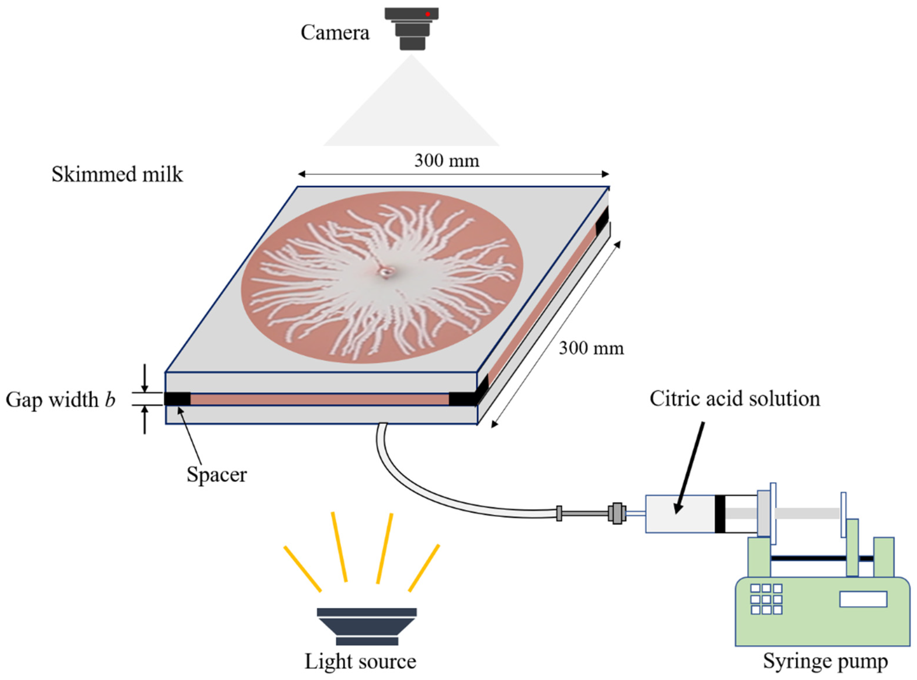
2.1. Experimental Setup

Figure 1 shows a schematic diagram of the experimental setup. The experiments were conducted using a Hele-Shaw cell, a device that has a small gap between two parallel glass plates that makes it possible to observe a two-dimensional flow pattern [37]. The area of the two square glass plates was 300 × 300 mm . A square copper block was placed as a spacer at each edge of the parallel glass plates. These spacers made it possible to adjust the gap width b between the two plates. In this work, the gap width b was varied from 0.4 to 0.8 mm to analyze its effect on the displacement patterns. The lower glass plate was equipped with a hole in the center for liquid injection. A camera Canon EOS 60D (Canon Inc., Tokyo, Japan) was installed at the top of the Hele-Shaw cell, and a video was taken when the displacing fluid was injected. A syringe pump KDS100 (KD Scientific Inc., Holliston, MA, USA) was used to inject fluid. In addition, a torch ESL-W2001AC (Asahi Electric Co., Ltd., Osaka, Japan) was located at the bottom of the experimental device to illuminate the Hele-Shaw cell so that shadows were not reflected in the recorded video.

2.2. Fluid Pair

The fluids used in this experiment were skim milk and aqueous citric acid solution. Skim milk is a nonfat milk that contains a relatively high amount of protein, of which approximately 80% is casein. Casein within skim milk is stable because the milk has a pH value of approximately 6.60. However, when acid is added to the milk, casein becomes unstable as the pH drops, approaching the isoelectric point (the least soluble pH value) of casein, which is at pH 4.6, resulting in isoelectric precipitation [38]. The aggregation of casein micelles resulting from isoelectric precipitation subsequently leads to viscoelastic gel formation, a typical gel formation found in the yogurt fermentation process [35,36].
The skim milk and the aqueous citric acid solution have an identical viscosity η of 2.07 mPa·s and 1.04–1.59 mPa·s, respectively. A low-viscosity ratio eliminates displacement instability caused by the viscosity difference [39]. The density ρ of the skim milk was 1.01 kg/m3 measured at a temperature of 22.80 °C. Skim milk powder was dissolved in water at a ratio of 10 g skim milk powder to 100 g of water. The protein content of this skim milk powder is 3.40 g for 10 g . Therefore, using weight percent (wt%) concentration, which is based on solute to solution ratio, the protein concentration of the solution used in this experiment was 3.1 wt%. The concentration was kept constant throughout the experiment. The food coloring mixtures were added to skim milk at a ratio of 0.10 g to 100 g of water to differentiate the skim milk and the aqueous citric acid solution. The skim milk was also doped with a methyl red pH indicator in several experiments to clearly observe the region where the gel emerged. Methyl red is a pH indicator that is yellow at a pH of more than 6 (skim milk pH value) and red at a pH of less than 4.6 (at which casein micelles precipitate) [40].
There were five concentrations of citric acid used in this experiment: 0.0 (pure water), 0.50, 1.5, 5.0, and 15 wt%. Table 1 shows the measured values for the density ρ, dynamic viscosity η, concentration c , and temperature T of citric acid.

2.3. Experimental Procedures

Two different types of experiments were conducted. In the first experiment, the displaced fluid was skim milk, whereas the displacing fluid was the aqueous citric acid solution (direct injection). The second experiment was a reverse injection experiment, in which the displaced and displacing fluids were exchanged accordingly. In both experiments, the Hele-Shaw cell was first saturated with the displaced fluid. After complete saturation, the displacing fluid was injected through a hole in the center of the lower glass plate of the Hele-Shaw cell. Displacement patterns were recorded using a digital camera. The experiment was stopped when the injected fluid volume reached 2 mL . The same procedure was repeated for experiments with different citric acid concentrations and injection rates Q (15–500 mL / h ).

3. Results and Discussion

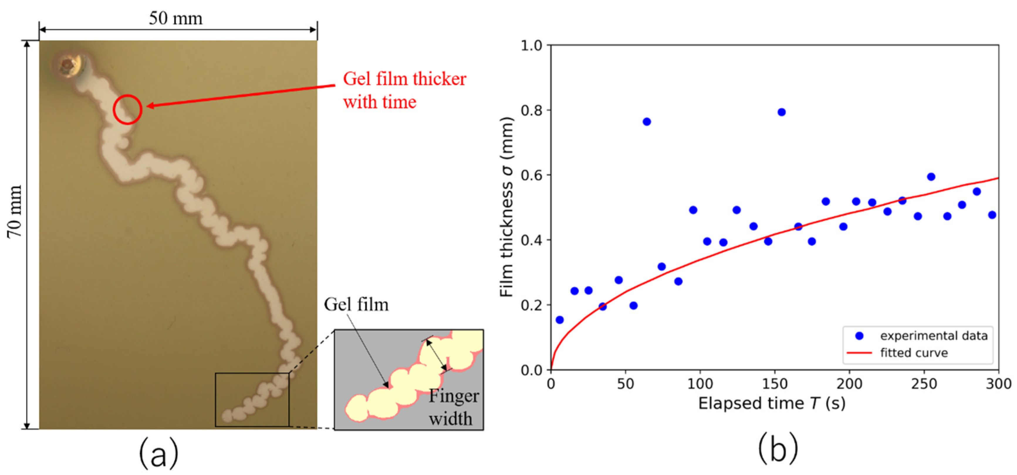
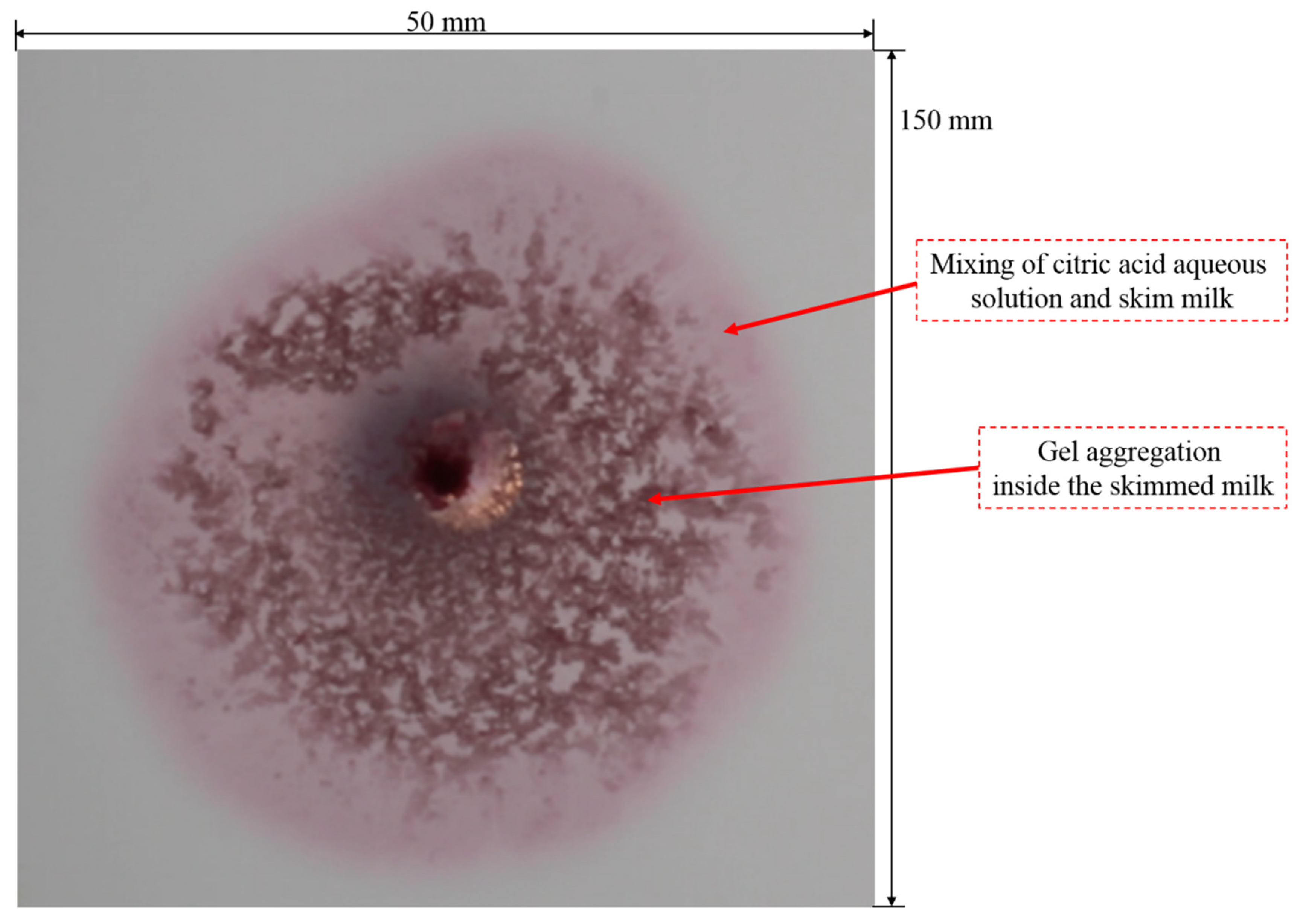
3.1. Typical Fingering Structure Induced by Gel Formation

Figure 2a shows the fingering pattern that emerges when aqueous citric acid solution displaces skim milk. The remarkable feature of this finger pattern is the presence of gel formation (red) that emerges at the interface between the skim milk and the aqueous citric acid solution. The gel formation acts as a continuous sidewall, preventing the finger from branching; thus, only the tip of the elongated finger continues to grow. This typical characteristic of the fingering pattern differentiates the fingering resulting from gel formation and the fingering caused by the viscosity difference [9].
The gel film formation thickens with time at the interface between the aqueous citric acid solution and skim milk. Figure 2b shows the sequential thickening of the gel film. The gel film thickness increases logarithmically with time. The gel film thickens faster in the early stage and gradually becomes constant. The thickening of the gel film is caused by the diffusion of the citric acid through the gel film formation, resulting in further mixing of skim milk and citric acid. The relation between the film thickness σ growth over time t and the diffusion coefficient constant D is expressed as follows [41]:
σ = 4 π D t
We used the least-squares method to estimate the diffusion coefficient D that best fit the observed data, excluding two outlier data points ( σ > 0.76 ) . The estimated D is 9.3 × 10 11   m 2 / s , with the coefficient of determination (R-squared), accounting for 72.5%. The estimated D is lower than the diffusion coefficient in a normal solution due to the bending of the diffusion path owing to gel formation. Moreover, unlike the diffusion phenomenon in uniform systems, the diffusion coefficient through the gel formation layer is not constant and depends on the solute concentration in the gel [42].

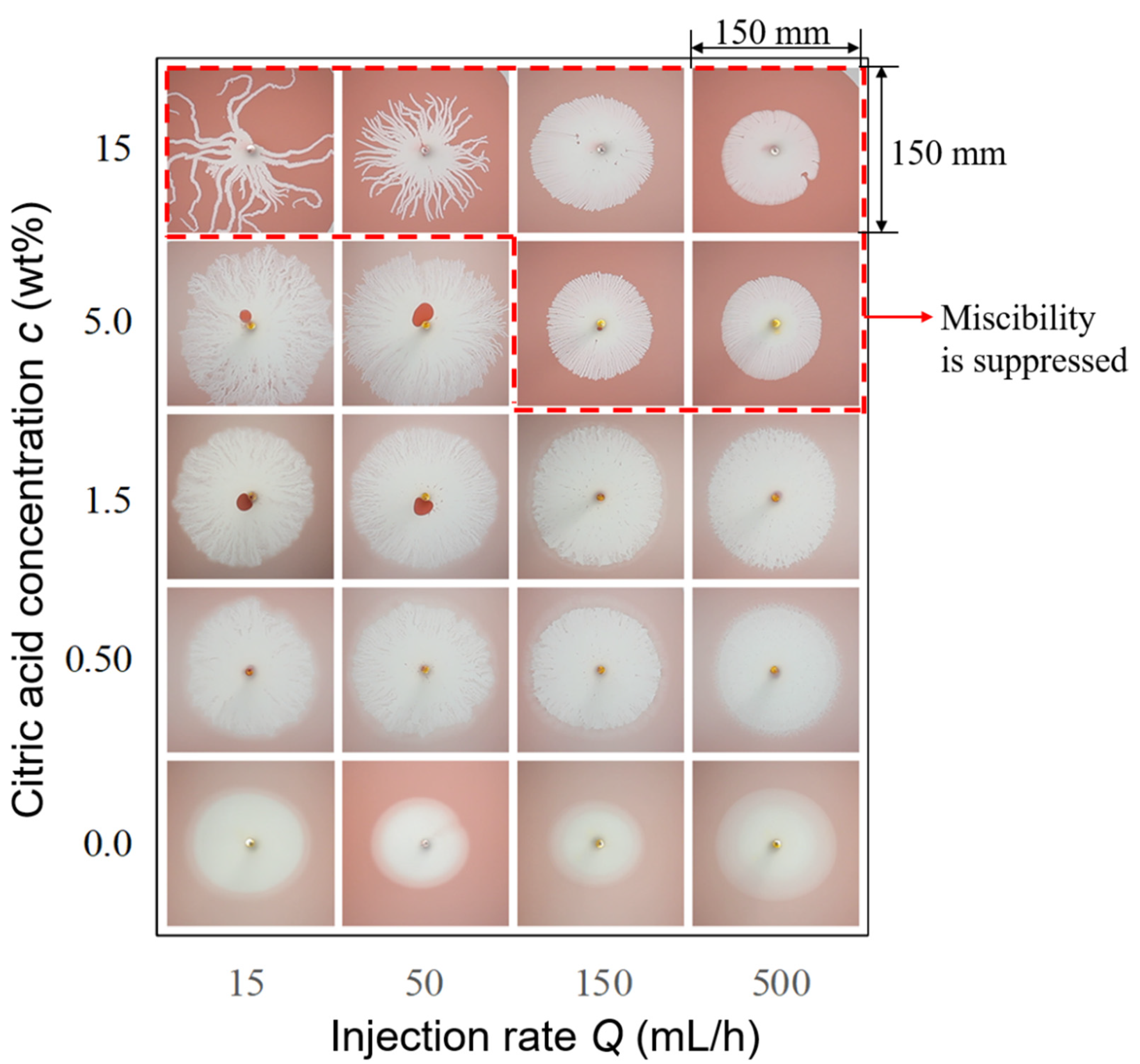
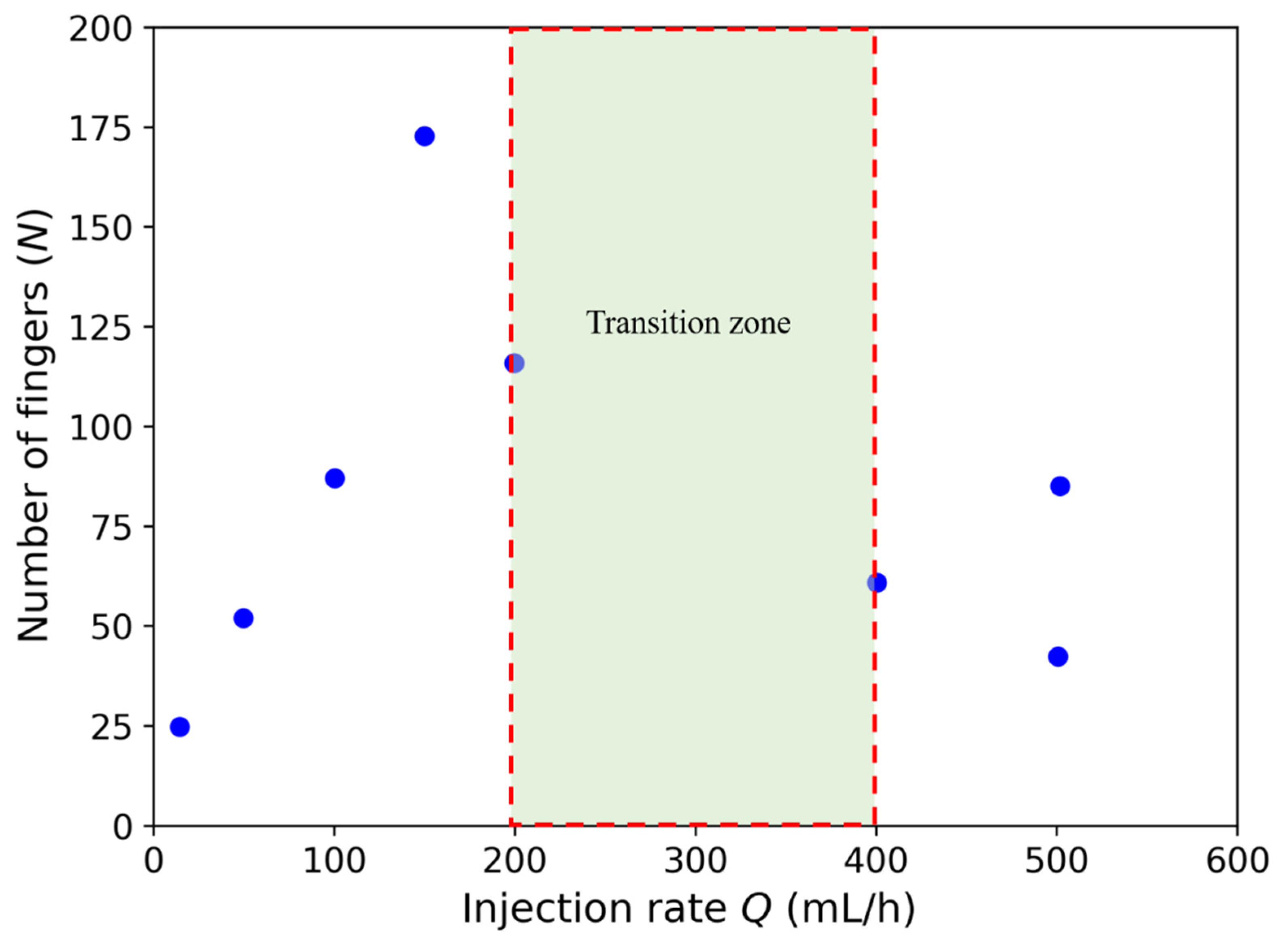
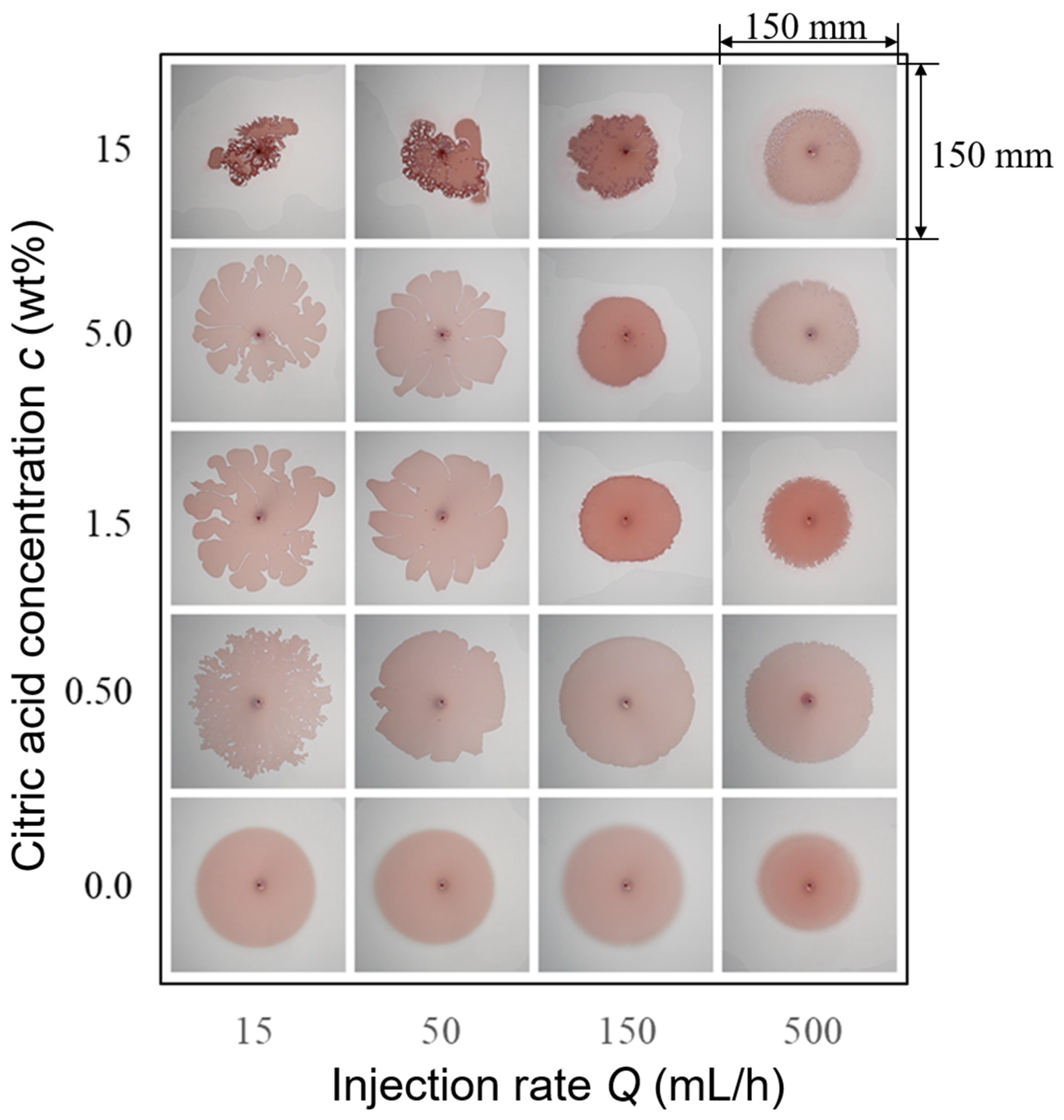
3.2. Effects of Injection Rate and Concentration of the Citric Acid on Displacement Pattern

We compared the fingering patterns that appeared under each condition when the injection rate and concentration of the citric acid were varied. Figure 3 shows the fingering patterns when citric acid is injected into skim milk under different injection rates and citric acid concentrations. Instability does not occur when pure water is used because no gel forms. However, the displacement becomes unstable when the citric acid concentration increases; thus, fingers emerge. The fingering pattern occurs because of casein precipitation at the interface, as the pH value decreases with increasing citric acid concentration. However, the displacement pattern becomes more stable with an increase in the injection rate.
The mixing between the skim milk and the aqueous citric acid solution occurs when the concentrations of the citric acid are 0.0, 0.50, 1.5 (all injection rates), and 5.0 wt% (injection rates of 15 and 50 mL / h ). The mixing part is represented by the color gradient between white and pink at the interface of the fluid pair. At a low concentration of citric acid, the miscibility is not suppressed because of insufficient gel formation at the interface of the fluid pair; thus, mixing occurs. Moreover, the small amount of gel formation enables branching of the finger to occur at the sidewall of the fingers, mimicking the displacement pattern of viscous fingering.
However, at a high citric acid concentration of 15 wt% (all injection rates) and 5 wt% (injection rates of 150 and 500 mL / h ), the mixing between the skim milk and the aqueous citric acid solution is suppressed. A high concentration of citric acid results in high casein precipitation, which turns into a large amount of gel formation and becomes a continuous wall at the interface between skim milk and aqueous citric acid solution. This gel formation hinders the miscibility of the two fluids.
Moreover, unlike the finger pattern that emerges when the aqueous citric acid solution is mixed with skim milk, remarkable fingering patterns, identical to tentacle-like structures, appear in the state where miscibility is suppressed (at a citric acid concentration of 15 wt% and injection rates of 15 and 50 mL / h ). The number of branches on the finger is extremely small. The gel formation prevents the finger from branching, as previously mentioned; hence, the growth of the finger is localized at the tip. When the finger reaches a certain length, the growth stops, and a new finger is generated from the base of the finger.
Figure 4 shows how the number of finger changes upon different injection rates Q , at a citric acid concentration of 15 wt%. Increasing the injection rate up to an injection rate of 200 mL / h leads to a linear increase in finger numbers. However, although the number of fingers increases, the finger width is constant. As a result, more fingers emerge to compensate for a larger injected volume of aqueous citric acid solution. When the injection rate is higher than 200 mL / h , the distance between the fingers becomes closer as the number of fingers increases. At this point, the number of fingers cannot increase anymore unless the finger width becomes small or the displacement front has traveled far enough from the injection point. As a result, the finger is likely to merge, denoted as the transition region in Figure 4. Further increasing the injection rate, therefore, decreases the total number of fingers.

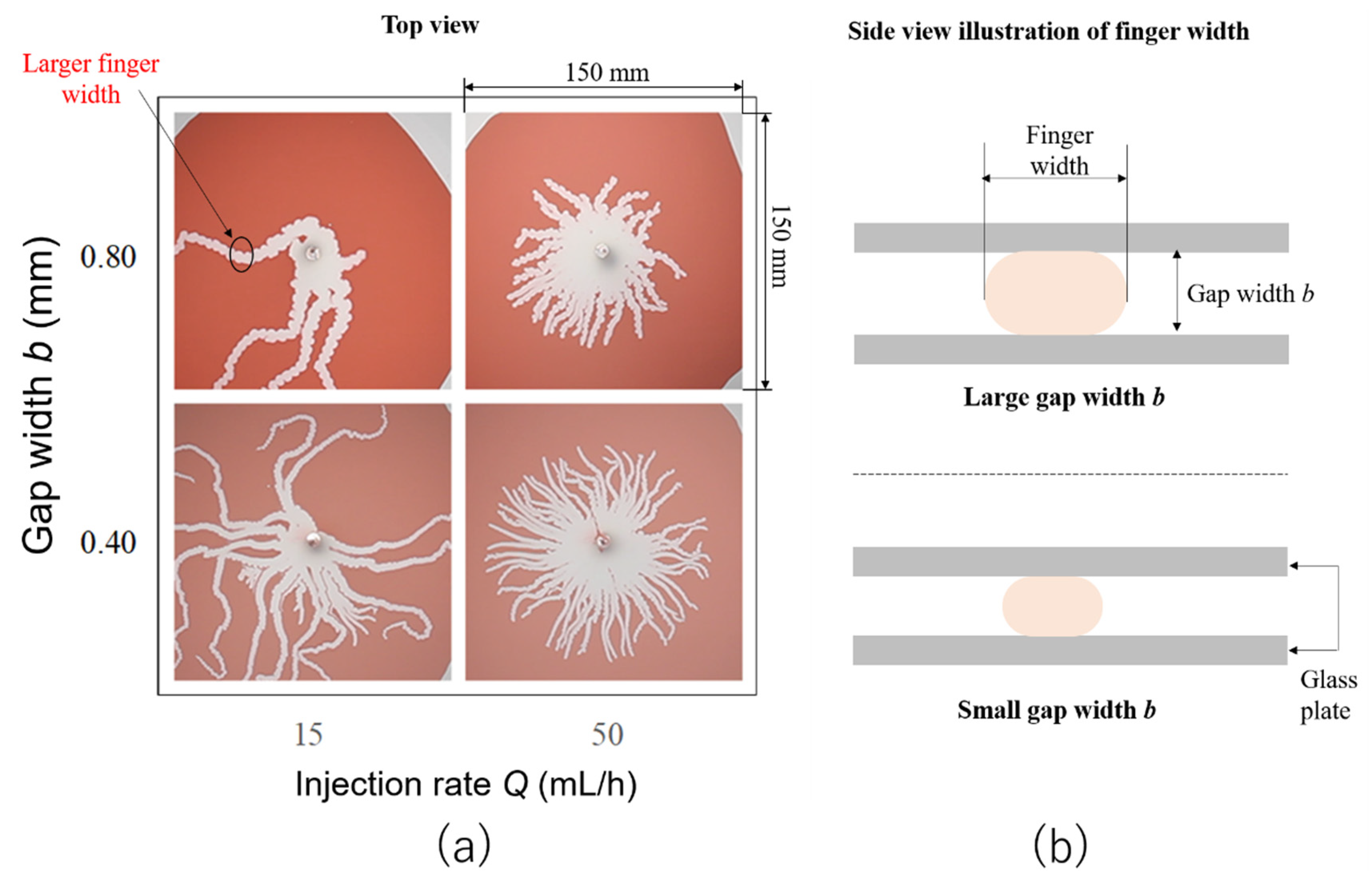
3.3. Gap Width Effects on the Finger Width

We expect that the finger width is significantly restricted by the gap width b . Therefore, we varied the gap width b from 0.4 to 0.8 mm and analyzed the results. Figure 5a shows a diagram of fingering patterns under four conditions with the change in gap width b and injection rates. In both gap width b conditions, the number of fingers increases when the injection flow rate increases, which is the same result as that discussed in the previous section. The typical fingering pattern is similar even when the gap width changes. However, finger width is reduced when the gap width b is smaller, whereas increasing the gap width b leads to a larger finger width. A larger finger width is accompanied by a decrease in the number of fingers. Figure 5a shows that approximately 25 fingers appear at a gap width b of 0.4 mm and an injection rate of 15 mL / h . However, at the same injection rate, the number of fingers decreases to only five when the gap width b is 0.8 mm . The decrease in the number of fingers compensates for the increased finger width at the same volume of the injected aqueous citric acid solution.
The proportional relation between the gap width b and finger width is subject to the tendency of the aqueous citric acid solution to have a sphere-like shape because of surface tension. When the gap width b is wider, the sphere-like shape of the aqueous citric acid solution also becomes larger and, thus, the finger width, as illustrated in Figure 5b. When the gap width b is smaller, however, the finger width also decreases. This result confirms that the finger width is significantly limited by the gap width b .

3.4. Reverse Injection Displacement Pattern (Skim Milk Injected into Citric Acid)

We also conducted experiments in which the displacing and displaced fluids were exchanged. The aqueous citric acid solution was first saturated in the Hele-Shaw cell as a displaced fluid, and skim milk was then injected as a displacing fluid. Figure 6 shows displacement patterns when the skim milk is injected into citric acid under different injection rates and citric acid concentrations. Stable displacement appears at a higher injection rate, whereas a higher citric acid concentration leads to displacement instability. The observed trend is similar to that when the fluid pair is not reversed. However, the displacement patterns are different. The growing front of the displacement pattern has a flower-like appearance of wide fingers. Such patterns might occur because of the asymmetry in the diffusion coefficients of the two mixing species. The precipitated casein likely has higher mobility in water (skim milk), reducing overall gel formation at the interface [18]. Resistance to finger widening was also reduced because there was a low amount of gel formation at the interface of the skim milk and aqueous citric acid solution.
Gel formation occupies the whole skim milk, at a citric acid concentration of 15 wt%. The area displaced by skim milk appears smaller (colored area), even though the injection volume is the same. This result suggests that the water from the milk leaks into citric acid and appears transparent, whereas gel formation accumulates close to the injection source.
To further confirm the mixing of water from milk with citric acid, additional experiments were performed by adding methyl red to the skim milk side. The displacement pattern when the skim milk was doped with the methyl red pH indicator is shown in Figure 7. The pink part is the mixing region where the water was contained in skim milk combined with the aqueous citric acid solution. This pink region is not observable in Figure 6; however, with the help of the methyl red pH indicator, this mixing region can be observed in Figure 7. The dark red indicates gel formation resulting from casein micelle precipitation. The dark red part spreads over the entire region of skim milk, which confirms that the precipitation of casein micelles is asymmetric and accumulated throughout the skim milk. Even at a high citric acid concentration, with a large amount of gel formation, mixing between skim milk and citric acid occurs because the gel does not solidify at the interface. Therefore, it can be inferred that the asymmetry of gel formation greatly affected the different displacement patterns between the reversed injection and direct injection experiments.

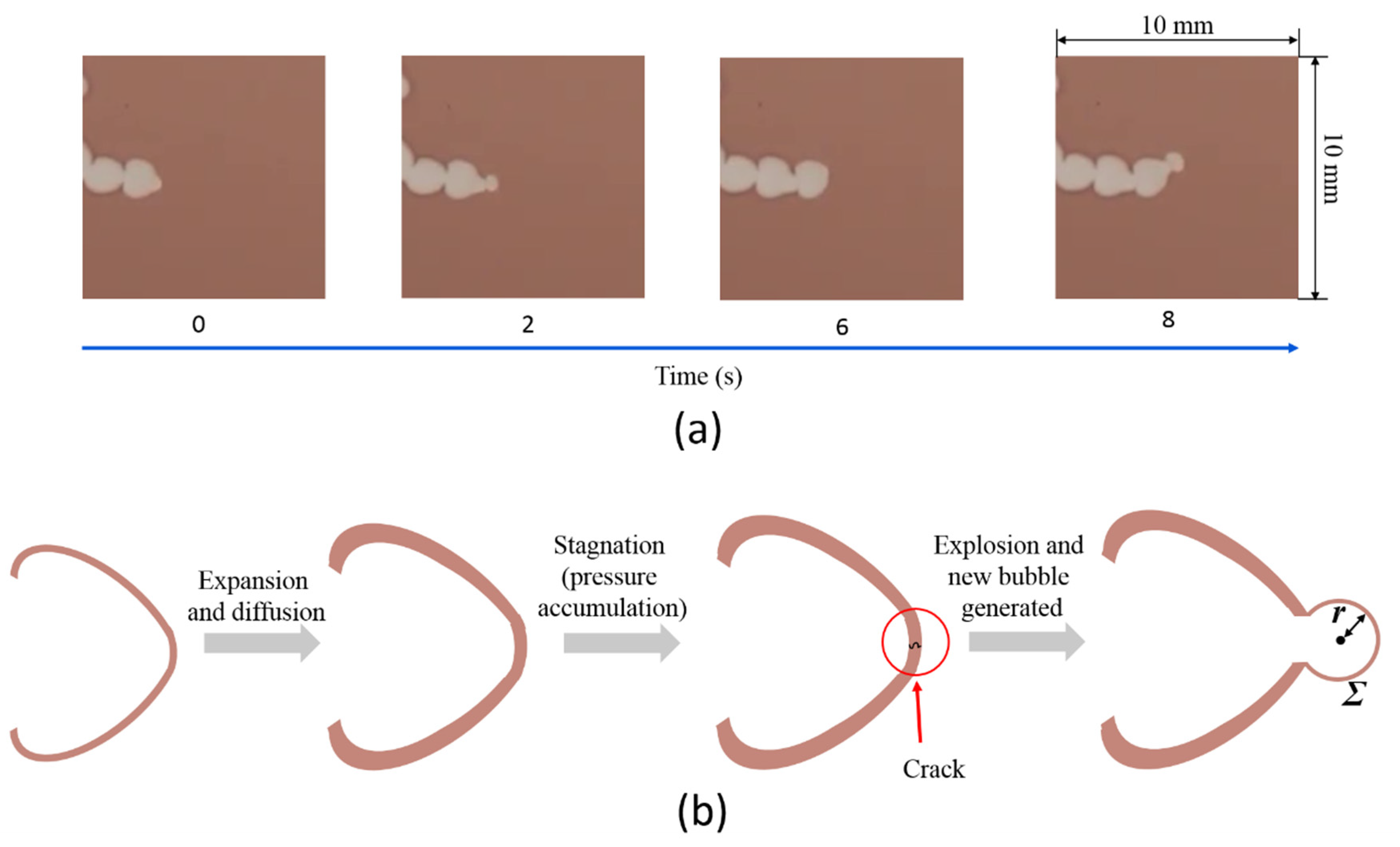
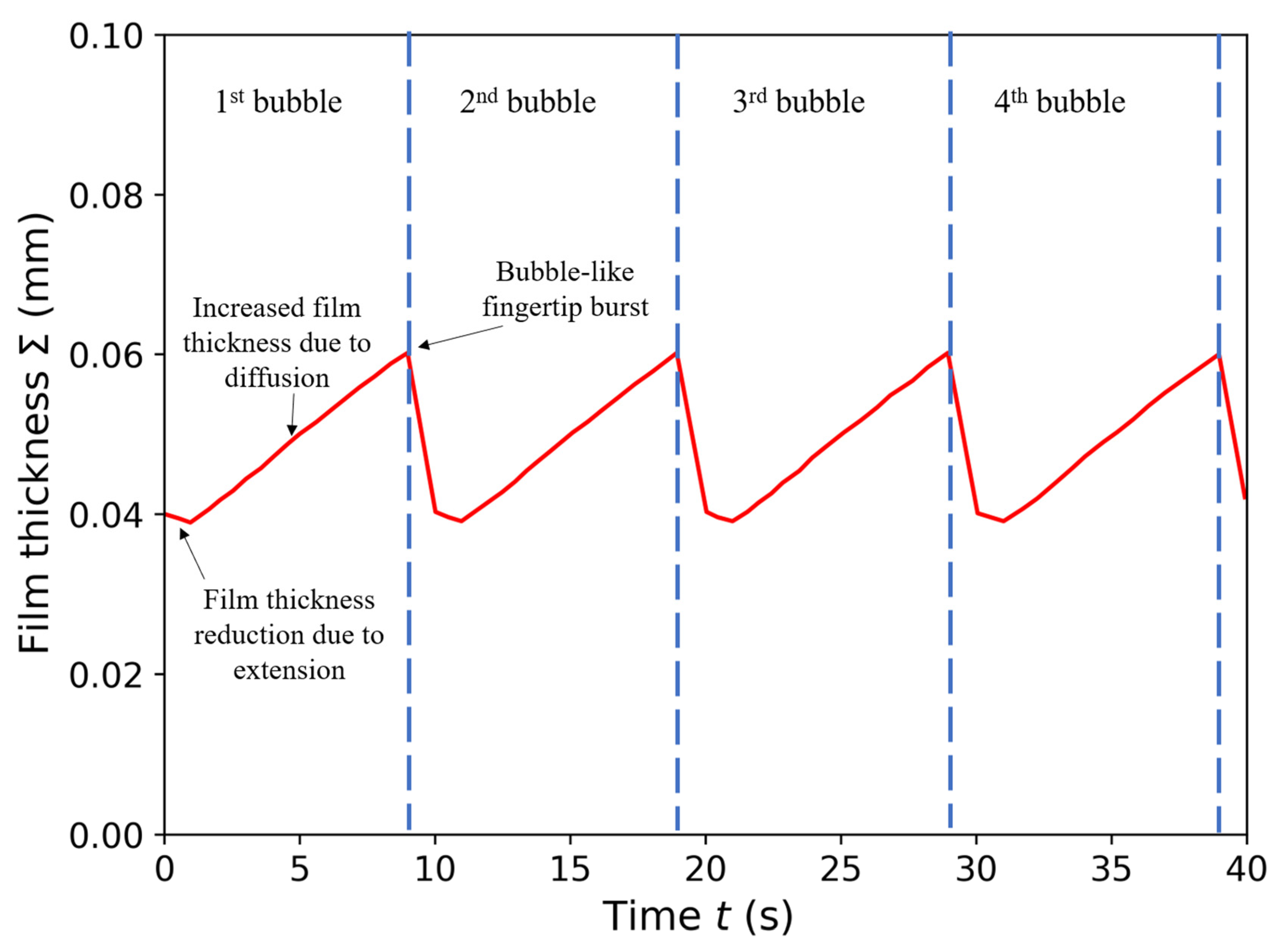
3.5. Mathematical Model of Sequential Growth of Gel Film Thickness at the Fingertip

Figure 8a shows the sequential growth of bubble-like fingers that emerges at a high citric acid concentration. The growth of this finger comprises a series of expansions, stagnations, and explosions that repeat over time. The pressure of the neighboring fingers does not influence the emerging bubble-like fingers. As shown in Figure 2a, even a single finger may possess this feature.
The reason why this structure appeared is because of the change in the gel film thickness over time. The film thickness decreases when the fingertip is elongated. However, the diffusion of citric acid through the existing gel formation increases the gel film thickness. Figure 8b illustrates the growth of the fingertip. Initially, the fingertip expands, resulting in a reduction in gel film thickness. However, at the same time, diffusion overcomes the elongation effect, resulting in a thicker gel film over time, while the fingertip continues to expand. At a certain point, the expansion stops because the gel film formation is sufficiently thick to act against the injection pressure. When finger growth stops, the pressure continues to increase. The increased pressure causes the gel film to burst. After the rupture, the finger grows again, and the pressure returns to its original state, marking the cycle repetition.
An attempt was made to mathematically model the change in the film thickness at the tip of the finger when this phenomenon occurred. First, the increase in the film thickness per unit time resulting from diffusion was derived. The time change in the film thickness owing to diffusion is expressed by Equation (1), based on Fick’s law. Differentiating Equation (1) for time, the increase in gel film thickness per unit time can be expressed as:
d σ d t = π D t
Next, the decrease in gel film thickness per unit time caused by extension was derived. When the number of fingers is one, the shape of the fingertip of a newly emerged bubble-like tip is modeled as a circle, the radius is r , the injection velocity is q , and the cell gap width is b . Then, the following equation holds from the preservation of the volume increase in the injected fluid:
2 π b r d r = Q d t
Integrating both sides of the above equation, one obtains
π b r 2 = Q t + C
Furthermore, if t = 0 and r = r0, the above equation can be expressed as
π b r 2 = Q t + π b r 0 2
Equation (3) can be rearranged as
d r d t = Q 2 π b r
If the thickness of the gel film is Σ, the following equation holds, according to the volume conservation law of the gel film:
2 π b r Σ = const
Differentiating Equation (7) with time t, the following equation is obtained:
d r d t Σ + r d Σ d t = 0
Based on Equations (5) and (6), Equation (8) can be expressed as
d Σ d t = 1 r d r d t Σ = q 2 π b r 2 Σ = 1 2 ( t + π b r 0 2 Q ) Σ
To obtain the overall change in film thickness with time, Equation (2) was combined with Equation (9), which represents the change in film thickness resulting from diffusion and fingertip expansion.
d Σ d t = π D t Σ 2 ( t + π b r 0 2 Q )
The above equation is transformed as follows for simplicity:
d Σ d t = π D t + π b r 0 2 q Σ 2 ( t + π b r 0 2 Q )
Furthermore, by solving Equation (11), the following equation is obtained:
Σ = π D t + C t + π b r 0 2 Q
This equation makes it possible to model the growth of the gel film thickness at the tip of the finger from the initial time when the bubble-like shape begins to expand until the bubble bursts. Assuming that r 0 is 0.4 mm, which is the same as the gap width, and C = 3.404 × 10 5   m s , the value such that the film thickness at t = 0 is 0.04 mm, a graph showing the sequential growth of film thickness at the tip of the finger can be obtained (Figure 9). At the initial state, t = 0, the film thickness decreases with the extension of the fingertip, whereas the effect of diffusion is insignificant. The film thickness reaches a minimum value at a certain point. After reaching the minimum point, the film thickness recovers and increases with time, owing to a significant diffusion effect. As the film thickness increases, the pressure at the fingertip is also expected to increase because finger extension is less likely to occur as the film thickness increases. As a result, the gel film cannot withstand the pressure, and a crack occurs at the tip of the gel film formation, resulting in a bubble-like finger burst. The tip of the finger repeatedly bursts at intervals of approximately 9 s, as expected, based on the experimental results shown in Figure 8a. When a bubble bursts, a new bubble-like tip emerges. This typical cycle repeats over time as more bubble-like fingertips are continuously generated.

4. Conclusions

In this study, we conducted Hele-Shaw cell displacement experiments using skim milk and aqueous citric acid solution to investigate the effects of gel film formation on the fingering instability of miscible fluids and develop a mathematical model for the sequential growth of gel film formation at the fingertip. We found that mixing skim milk and an aqueous citric acid solution induces gel film formation, resulting in interface instability. A distinctive feature of the fingering pattern, such as tentacles, appears when miscibility is suppressed, and the growth of the finger is localized at the fingertip. The gel film formation thickens with time owing to the diffusion of citric acid through the existing gel film formation.
The finger width remains constant with increasing flow rate, whereas the number of fingers increases linearly. However, at a certain point, where the injection rate is too high to be compensated by the increase in the number of fingers, the fingers merge and the number of fingers decreases. The finger patterns that appear at each injection rate are similar, regardless of the gap width. However, the finger width increases with the gap width. In addition, the growing front of the displacement pattern has a flower-like appearance of wide fingers when the displaced and displacing fluids are exchanged.
The growth of the bubble-like fingertip comprises a series of expansions, stagnations, and explosions that repeats over time. A mathematical model of sequential film thickness growth for a bubble-like fingertip structure was developed. The model is based upon the interplay between the diffusion of citric acid through the existing gel film formation and elongation of the fingertip, which provides an understanding of the fundamental mechanism for the growth of the bubble-like fingertip, owing to gel film formation. This model is potentially relevant to various processes, including the growth of bacterial biofilms [19] and fingering instability in confined chemical gardens [24,25]. The results of this investigation can also be a reference for engineering applications, such as remediation of potential CO2 leakage from storage reservoirs [27,28] and enhanced heavy oil recovery methods based on alkali flooding [29,30]. We believe that future research must be directed toward further analysis based on pore-scale studies using a porous medium structure that resembles the structure of geological formation. Pore-scale studies offer a detailed observation for the underlying mechanisms, which are macroscopically unobserved [43].

Author Contributions

Conceptualization, T.S. and R.Y.; methodology, M.N., R.Y. and Y.S.; validation, A.P., M.A.M. and Z.L.; formal analysis, M.N., R.Y. and W.W; investigation, R.Y., Y.S. and W.W.; writing—original draft preparation, M.N. and R.Y.; writing—review and editing, M.N., A.P. and M.A.M.; visualization, M.N. and Z.L.; supervision, S.M., A.P. and T.S.; project administration, S.M.; funding acquisition, A.P. and T.S. All authors have read and agreed to the published version of the manuscript.

Funding

This study was supported by the Japan Society for the Promotion of Science KAKENHI (grant numbers 17H00790 and 20J14975), InfoSyEnergy Program Tokyo Institute of Technology, and Indonesia Endowment Fund for Education (LPDP).

Institutional Review Board Statement

Not applicable.

Informed Consent Statement

Not applicable.

Data Availability Statement

The data presented in this study are available on request from the corresponding author.

Conflicts of Interest

The authors declare no conflict of interest.

References

  1. Ghatak, A.; Chaudhury, M.K.; Shenoy, V.; Sharma, A. Meniscus Instability in a Thin Elastic Film. Phys. Rev. Lett. 2000, 85, 4329–4332. [Google Scholar] [CrossRef] [Green Version]
  2. Sandnes, B.; Flekkoy, E.G.; Knudsen, H.A.; Maloy, K.J.; See, H. Patterns and flow in frictional fluid dynamics. Nat. Commun. 2011, 2, 288. [Google Scholar] [CrossRef] [PubMed] [Green Version]
  3. Chaudhury, M.K.; Chakrabarti, A.; Ghatak, A. Adhesion-induced instabilities and pattern formation in thin films of elastomers and gels. Eur. Phys. J. E 2015, 38, 82. [Google Scholar] [CrossRef] [PubMed] [Green Version]
  4. Sakai, S.; Nakanishi, Y.; Hyodo, A.; Wang, L.; Suekane, T. Three-dimensional fingering structure associated with gravitationally unstable mixing of miscible fluids in porous media. Heat Transf. Res. 2018, 49, 1023–1039. [Google Scholar] [CrossRef]
  5. Nagatsu, Y.; Ishii, Y.; Tada, Y.; De Wit, A. Hydrodynamic Fingering Instability Induced by a Precipitation Reaction. Phys. Rev. Lett. 2014, 113, 024502. [Google Scholar] [CrossRef] [Green Version]
  6. Patmonoaji, A.; Hu, Y.; Nasir, M.; Zhang, C.; Suekane, T. Effects of Dissolution Fingering on Mass Transfer Rate in Three-Dimensional Porous Media. Water Resour. Res. 2021, 57, e2020WR029353. [Google Scholar] [CrossRef]
  7. Saffman, P.G. Viscous fingering in Hele-Shaw cells. J. Fluid Mech. 1986, 173, 73–94. [Google Scholar] [CrossRef] [Green Version]
  8. Stewart, S.; Marin, D.; Tullier, M.; Pojman, J.; Meiburg, E.; Bunton, P. Stabilization of miscible viscous fingering by a step growth polymerization reaction. Exp. Fluids 2018, 59, 114. [Google Scholar] [CrossRef]
  9. Sin, S.; Suekane, T.; Nagatsu, Y.; Patmonoaji, A. Three-dimensional visualization of viscous fingering for non-Newtonian fluids with chemical reactions that change viscosity. Phys. Rev. Fluids 2019, 4, 054502. [Google Scholar] [CrossRef]
  10. Nagatsu, Y.; Kondo, Y.; Kato, Y.; Tada, Y. Effects of moderate Damköhler number on miscible viscous fingering involving viscosity decrease due to a chemical reaction. J. Fluid Mech. 2009, 625, 97–124. [Google Scholar] [CrossRef]
  11. Sorbie, K.S.; Al Ghafri, A.Y.; Skauge, A.; Mackay, E.J. On the Modelling of Immiscible Viscous Fingering in Two-Phase Flow in Porous Media. Transp. Porous Media 2020, 135, 331–359. [Google Scholar] [CrossRef]
  12. Hewitt, D.R.; Neufeld, J.A.; Lister, J.R. Convective shutdown in a porous medium at high Rayleigh number. J. Fluid Mech. 2013, 719, 551–586. [Google Scholar] [CrossRef] [Green Version]
  13. Forbes, L.K.; Browne, C.A.; Walters, S.J. The Rayleigh–Taylor instability in a porous medium. SN Appl. Sci. 2021, 3, 188. [Google Scholar] [CrossRef]
  14. Livescu, D.; Wei, T.; Brady, P. Rayleigh–Taylor instability with gravity reversal. Phys. D Nonlinear Phenom. 2021, 417, 132832. [Google Scholar] [CrossRef]
  15. Wang, T.-S.; Shi, W.-Y. Marangoni instability induced by evaporation in well-defined non-spherical sessile droplet. Int. J. Heat Mass Transf. 2019, 141, 168–179. [Google Scholar] [CrossRef]
  16. Li, Y.; Meijer, J.G.; Lohse, D. Marangoni instabilities of drops of different viscosities in stratified liquids. J. Fluid Mech. 2021, 932. [Google Scholar] [CrossRef]
  17. Li, Y.; Diddens, C.; Prosperetti, A.; Lohse, D. Marangoni Instability of a Drop in a Stably Stratified Liquid. Phys. Rev. Lett. 2021, 126, 124502. [Google Scholar] [CrossRef]
  18. Podgorski, T.; Sostarecz, M.C.; Zorman, S.; Belmonte, A. Fingering instabilities of a reactive micellar interface. Phys. Rev. E-Stat. Nonlinear Soft Matter Phys. 2007, 76, 016202. [Google Scholar] [CrossRef] [Green Version]
  19. Goriely, A.; Tabor, M. Self-Similar Tip Growth in Filamentary Organisms. Phys. Rev. Lett. 2003, 90, 108101. [Google Scholar] [CrossRef] [Green Version]
  20. Tronnolone, H.; Tam, A.; Szenczi, Z.; Green, J.E.F.; Balasuriya, S.; Tek, E.L.; Gardner, J.M.; Sundstrom, J.F.; Jiranek, V.; Oliver, S.; et al. Diffusion-Limited Growth of Microbial Colonies. Sci. Rep. 2018, 8, 5992. [Google Scholar] [CrossRef] [Green Version]
  21. Matsushita, M.; Fujikawa, H. Diffusion-limited growth in bacterial colony formation. Phys. A Stat. Mech. Its Appl. 1990, 168, 498–506. [Google Scholar] [CrossRef]
  22. Schwarcz, D.; Levine, H.; Ben-Jacob, E.; Ariel, G. Uniform modeling of bacterial colony patterns with varying nutrient and substrate. Phys. D Nonlinear Phenom. 2016, 318–319, 91–99. [Google Scholar] [CrossRef] [Green Version]
  23. Mimura, M.; Sakaguchi, H.; Matsushita, M. Reaction–diffusion modelling of bacterial colony patterns. Phys. A Stat. Mech. Its Appl. 2000, 282, 283–303. [Google Scholar] [CrossRef]
  24. Haudin, F.; Cartwright, J.H.E.; Brau, F.; De Wit, A.; Takayama, K.; Morisaki, Y.; Kuno, S.; Nagamoto, Y.; Harada, K.; Furukawa, N.; et al. Spiral precipitation patterns in confined chemical gardens. Proc. Natl. Acad. Sci. USA 2014, 111, 17363–17367. [Google Scholar] [CrossRef] [Green Version]
  25. Haudin, F.; Cartwright, J.H.E.; De Wit, A. Direct and Reverse Chemical Garden Patterns Grown upon Injection in Confined Geometries. J. Phys. Chem. C 2015, 119, 15067–15076. [Google Scholar] [CrossRef]
  26. Haudin, F.; Brasiliense, V.; Cartwright, J.H.E.; Brau, F.; De Wit, A. Genericity of confined chemical garden patterns with regard to changes in the reactants. Phys. Chem. Chem. Phys. 2015, 17, 12804–12811. [Google Scholar] [CrossRef] [Green Version]
  27. Syed, A.; Pantin, B.; Durucan, S.; Korre, A.; Shi, J.Q. The use of polymer-gel solutions for remediation of potential CO2 leakage from storage reservoirs. Energy Procedia 2014, 63, 4638–4645. [Google Scholar] [CrossRef] [Green Version]
  28. Ito, T.; Xu, T.; Tanaka, H.; Taniuchi, Y.; Okamoto, A. Possibility to remedy CO2 leakage from geological reservoir using CO2 reactive grout. Int. J. Greenh. Gas Control 2014, 20, 310–323. [Google Scholar] [CrossRef]
  29. Mahardika, M.A.; She, Y.; Shori, F.; Patmonoaji, A.; Matsushita, S.; Suekane, T.; Nagatsu, Y. Enhanced Heavy Oil Recovery by Calcium Hydroxide Flooding with the Production of Viscoelastic Materials: Study with 3-D X-Ray Tomography and 2-D Glass Micromodels. Energy Fuels 2021, 35, 11210–11222. [Google Scholar] [CrossRef]
  30. Nagatsu, Y.; Abe, K.; Konmoto, K.; Omori, K. Chemical Flooding for Enhanced Heavy Oil Recovery via Chemical-Reaction-Producing Viscoelastic Material. Energy Fuels 2020, 34, 10655–10665. [Google Scholar] [CrossRef]
  31. Coutinho, M.; Rocha, F.M.; Miranda, J.A. Viscous normal stresses and fingertip tripling in radial Hele-Shaw flows. Phys. Rev. E 2021, 104, 045106. [Google Scholar] [CrossRef]
  32. Suzuki, R.X.; Kobayashi, S.; Nagatsu, Y.; Ban, T. Tunable Hydrodynamic Interfacial Instability by Controlling a Thermodynamic Parameter of Liquid–Liquid Phase Separation. J. Phys. Chem. B 2021, 125, 7508–7514. [Google Scholar] [CrossRef] [PubMed]
  33. Stergiou, Y.; Eckert, K.; Schwarzenberger, K. Entrance effects in a radial Hele-Shaw cell: Numerical and experimental study. Chem. Eng. J. 2022, 428, 131146. [Google Scholar] [CrossRef]
  34. Cieślik, A.; Akkermans, R.; Kamp, L.; Clercx, H.J.; van Heijst, G. Dipole-wall collision in a shallow fluid. Eur. J. Mech.-B/Fluids 2009, 28, 397–404. [Google Scholar] [CrossRef]
  35. Lee, W.; Lucey, J. Structure and Physical Properties of Yogurt Gels: Effect of Inoculation Rate and Incubation Temperature. J. Dairy Sci. 2004, 87, 3153–3164. [Google Scholar] [CrossRef]
  36. Bönisch, M.P.; Huss, M.; Lauber, S.; Kulozik, U. Yoghurt gel formation by means of enzymatic protein cross-linking during microbial fermentation. Food Hydrocoll. 2007, 21, 585–595. [Google Scholar] [CrossRef]
  37. Wang, W.; Zhang, C.; Patmonoaji, A.; Hu, Y.; Matsushita, S.; Suekane, T.; Nagatsu, Y. Effect of gas generation by chemical reaction on viscous fingering in a Hele–Shaw cell. Phys. Fluids 2021, 33, 093104. [Google Scholar] [CrossRef]
  38. Zittle, C. Precipitation of Casein from Acidic Solutions by Divalent Anions. J. Dairy Sci. 1966, 49, 361–364. [Google Scholar] [CrossRef]
  39. Etrati, A.; Alba, K.; Frigaard, I.A. Two-layer displacement flow of miscible fluids with viscosity ratio: Experiments. Phys. Fluids 2018, 30, 052103. [Google Scholar] [CrossRef]
  40. Chairunisa, W.; Imawan, C. The effect of pH on the characteristics of the methyl red solution as a gamma-ray dosimeter. J. Phys. Conf. Ser. 2019, 1321, 022015. [Google Scholar] [CrossRef] [Green Version]
  41. Wang, L.; Nakanishi, Y.; Teston, A.D.; Suekane, T. Effect of diffusing layer thickness on the density-driven natural convection of miscible fluids in porous media: Modeling of mass transport. J. Fluid Sci. Technol. 2018, 13, JFST0002. [Google Scholar] [CrossRef] [Green Version]
  42. Muhr, A.H.; Blanshard, J.M. Diffusion in gels. Polymer 1982, 23, 1012–1026. [Google Scholar] [CrossRef]
  43. Patmonoaji, A.; Mahardika, M.A.; Nasir, M.; She, Y.; Wang, W.; Muflikhun, M.A.; Suekane, T. Stereolithography 3D Printer for Micromodel Fabrications with Comprehensive Accuracy Evaluation by Using Microtomography. Geosciences 2022, 12, 183. [Google Scholar] [CrossRef]
Figure 1. Schematic diagram of the experimental setup.
Applsci 12 05043 g001
Figure 2. (a) A typical finger structure consists of bubble-like patterns with gel formation (red) generated at a 15 wt% concentration of the citric acid, an injection rate Q of 1.0 mL / h , and a gap width b of 0.4 mm . The skim milk was doped with a methyl red pH indicator. (b) The sequential thickening of the gel film at the interface of the skim milk and aqueous citric acid solution. The blue dot represents the experimental result, whereas the red line is the fitting curve based on Equation (1).
Applsci 12 05043 g002
Figure 3. Displacement patterns when citric acid (white) is injected into skim milk (pink) upon injection rates of 15, 50, 150, and 500 mL/h and citric acid concentrations of 0.0 (pure water), 0.50, 1.5, 5.0, and 15 wt%. Images are taken when the injection volume of the aqueous citric acid solution is 2 mL and the gap width b is 0.4 mm. The red dash line represents the conditions at which the miscibility of citric acid and skim milk is suppressed.
Applsci 12 05043 g003
Figure 4. Relationship of injection rate Q with respect to the number of fingers N at a citric acid concentration c = 15 wt% (when the volume of the injected aqueous citric acid solution is 2 mL and the gap width b is 0.4 mm). The transition zone represents the region at which the fingers begin to merge.
Applsci 12 05043 g004
Figure 5. (a) Top view of displacement patterns when the gap widths are 0.4 and 0.8 mm and injection rates were varied from 15 to 50 mL / h . The volume of the injected aqueous citric acid solution is 2 mL. (b) Side view illustration of how the finger width changes with gap width b . The sphere-like shape represents the aqueous citric acid solution.
Applsci 12 05043 g005
Figure 6. Displacement patterns when skim milk (pink) is injected into citric acid (white) upon injection rates of 15, 50, 150, and 500 mL/h and citric acid concentrations of 0.0 (pure water), 0.50, 1.5, 5.0, and 15 wt%. Images were taken when the injection volume was 2 mL, and the gap width b was 0.4 mm.
Applsci 12 05043 g006
Figure 7. Displacement pattern when the skim milk doped with methyl red is injected into the aqueous citric acid solution. The dark red part is the gel resulting from precipitated casein micelles, whereas the pink part is the water separated from the gel. The image was captured at the initial injection stage when the skim milk was injected into the aqueous citric acid solution, and the skim milk injection volume was 0.4 mL. The citric acid concentration c was 15 wt% at an injection rate Q of 15 mL/h and a gap width b of 0.4 mm.
Applsci 12 05043 g007
Figure 8. (a) Sequential growth of bubble-like finger structure that appears at a citric acid concentration c of 15 wt%, injection speed Q of 15 mL / h , and gap width b of 0.4 mm. (b) Illustration of the growth of fingertip comprising expansion, stagnation, and explosion.
Applsci 12 05043 g008
Figure 9. Sequential change in the interfacial gel film thickness based on Equation (12) considering periodic rupture at the fingertip. The parameters are set as follows: D = 9.3 × 10 11   m 2 / s , b = 0.4 mm, Q = 1.0 mL/h, r0 = 0.4 mm, and C = 3.404 × 10 5   m s . The film thickness changes from decreasing to monotonically increasing as a one-cycle bubble formation. Periodic rupture occurs approximately every 9 s.
Applsci 12 05043 g009
Table 1. Measured values of density ρ, viscosity η, and temperature T at each concentration c of the citric acid used in the experiment.
c [wt%] ρ [kg/m3] η [mPa·s] T [°C]
0.01.001.1718.8
0.50.991.0421.8
1.50.991.1221.1
5.01.001.1820.7
151.051.5922.8
Publisher’s Note: MDPI stays neutral with regard to jurisdictional claims in published maps and institutional affiliations.

