Abstract
In this study, quasi-unidirectional continuous fiber reinforced thermoplastics (CFRTs) are joined with metal sheets via cold formed cylindrical, elliptical and polygonal pin structures which are directly pressed into the CFRT component after local infrared heating. In comparison to already available studies, the unique novelty is the use of non-rotational symmetric pin structures for the CFRT/metal hybrid joining. Thus, a variation in the fiber orientation in the CFRT component as well as a variation in the non-rotational symmetric pins’ orientation in relation to the sample orientation is conducted. The created samples are consequently mechanically tested via single lap shear experiments in a quasi-static state. Finally, the failure behavior of the single lap shear samples is investigated with the help of microscopic images and detailed photographs. In the single lap shear tests, it could be shown that non-rotational symmetric pin structures lead to an increase in maximum testing forces of up to 74% when compared to cylindrical pins. However, when normalized to the pin foot print related joint strength, only one polygonal pin variation showed increased joint strength in comparison to cylindrical pin structures. The investigation of the failure behavior showed two distinct failure modes. The first failure mode was failure of the CFRT component due to an exceedance of the maximum bearing strength of the pin-hole leading to significant damage in the CFRT component. The second failure mode was pin-deflection due to the applied testing load and a subsequent pin extraction from the CFRT component resulting in significantly less visible damage in the CFRT component. Generally, CFRT failure is more likely with a fiber orientation of 0° in relation to the load direction while pin extraction typically occurs with a fiber orientation of 90°. It is assumed that for future investigations, pin structures with an undercutting shape that creates an interlocking joint could counteract the tendency for pin-extraction and consequently lead to increased maximum joint strengths.
1. Introduction
Hybrid parts consisting of continuous fiber reinforced thermoplastics (CFRTs) and high strength steel components offer interesting possibilities in use-cases with challenges that cannot be met with mono-material parts. One possible example is the combination of a demand for lightweight construction, where CFRTs can offer superior weight-related properties [1], with locally high thermal or abrasive stress, where CFRTs typically meet limitations [2]. This could be resolved with the combination of metal components to form a hybrid part. In this approach, the joining operation is the key challenge due to strongly diverging physical and chemical properties such as stiffness and thermal expansion coefficients. In the state of the art, bolted and riveted joints are commonly used; as for these joints, a comprehensive knowledge is available in the literature and it is possible to create strong and durable joints [3]. However, despite their widespread use, these form-fitting joining techniques come with relevant disadvantages. First, the need for a precise bolt hole [4] requires an additional process step, which increases processing costs and typically destroys load-bearing fibers. This can require additional reinforcements such as locally embedded titanium sheets or additional layers in the laminate. Furthermore, the need for additional auxiliary elements such as bolts, nuts and rivets leads to increased weight of the structure, which contradicts the idea of lightweight construction [5]. A fiber-friendly joining technology is the use of adhesives. While adhesive joining leads to an even introduction of force into the laminate, which reduce concentration of tension and typically does not require additional reinforcements [6], it also comes with distinct challenges, including the demand for extensive process quality control to ensure a reliable joint and especially with thermoplastic composites, joinability via adhesives is oftentimes limited. Polyolephinic polymers especially require surface treatment to be joinable via adhesives that add process steps and complexity to the joining process [7].
A comparably new joining process is the creation of form fitting joints via cold formed pin structures, which can embedded into the locally heated CFRT component [8]. In the field of thermoset-based composite (CFRP)/metal joining, the use of pin-reinforced adhesive joints is already widely described. However, in CFRP/metal joining, the pin needs to be embedded during the manufacturing process of the part [9]. This can either be into the dry fabric prior to the infusion process via vacuum assisted resin infusion [10], vacuum assisted resin transfer molding [11] or into pre-impregnated sheet during manufacturing before the curing stage of the matrix [12]. Thus, a separate, subsequent joining process is not possible. In the field of CFRT/metal joining, the direct pin pressing process into a locally heated CFRT component has been shown to be an uncomplicated joining process with promising mechanical properties [13]. In the current state of the art, rotational-symmetric pins have been primarily investigated [14], although in Römisch et al. [15], the uses of non-rotational-symmetric pins have shown potential to increase the maximum load of the joint in the field of metal to aluminum hybrid joining. Due to the good performance in metal/metal joining, the use of non-rotational-symmetric pin structures also appears promising in the use of CFRT/metal joining. However, the underlying mechanisms in the direct pin pressing of CFRT/metal parts are fundamentally diverse for steel/aluminum joining and consequently, a direct transfer of the knowledge from Römisch et al. [15] is not possible. In particular, the joints’ dependency on the pin- and fiber orientation of the anisotropic CFRT material in relation to the load direction needs to be investigated.
Considering the existing literature, the present study aims to create an understanding of the CFRT/metal joining process with non-rotational-symmetric pin structures. The focus thereby lies on the mechanical behavior in dependency of the pin- and fiber orientation in relation to the load direction and the investigation of occurring failure modes.
2. Materials and Methods
2.1. Used Material
In this study, a custom-fabricated quasi-unidirectional glass fiber reinforced polypropylene (GF/PP) material with a thickness of approximately 2 mm was used. Thus, glass fiber non-crimp fabrics from Saertex GmbH & Co. KG (Saerbeck, Germany) and a polypropylene (PP) type BJ100HP from Borealis AG (Vienna, Austria) were impregnated and consolidated on an interval hot press at the Neue Materialien Fürth GmbH (Fürth, Germany). The residual after incineration was measured to 71.1 wt.-%, which translates to a fiber volume content under the assumption of ideal consolidation of 47 vol.-%. The melt peak temperature of the composite was measured to 164.4 °C and the crystallization peak temperature was measured to 121.4 °C both as an average of nine differential scanning calorimetry (DSC) measurements.
As a steel component, a galvanized dual-phase steel type HCT590X (DP600) from Salzgitter AG (Salzgitter, Germany) was used. This cold-rolled steel variant was frequently used in the automotive sector for a crash relevant component of the car body. The thickness of the used steel sheets was 1.5 mm.
2.2. Definition of Pin Geometry
In the scope of this study, three different pin geometries with a height of 1.8 mm were investigated. As a baseline geometry, which aims to create a comparability between the different non-rotational symmetric pins as well as a comparability to sources in the literature, which primarily use cylindrical pin structures, a cylindrical pin with a diameter of 1 mm was chosen. As a pin with a strong directional dependency in means of fiber displacement and behavior under load, an elliptical pin with a small diameter of 1 mm and a large diameter of 2 mm was chosen. As a third geometry with an anisotropic behavior under compressive and tensile loading, a polygonal pin structure was chosen, which is based on a triangular geometry. It has an in-circle diameter of 1 mm; the sides are curved with a radius of 1.18 while the edges are rounded with a radius of 0.1 mm. Figure 1 displays the three investigated geometries.
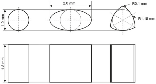
Figure 1.
Used pin geometries: cylindrical (left), elliptical (middle), polygonal (right).
The investigated geometries feature different cross sections, volumes and projection areas (for elliptical pins in dependency of the viewing angle) which are summarized in Table 1. These values allow for assessing the efficiency of a pin-geometry in means of used foot-print on the sample and mechanical performance of the created joints.

Table 1.
Geometric properties of pin geometries.
2.3. Pin Manufacturing via Cold Forming Process
For the production of the pin geometries described above, forward extrusion from the sheet metal plane was used. For this purpose, a multiple-acting tool is required to ensure independent control of the blank holder as well as the punch. The process sequence of the pin extrusion as well as the essential tool components for the extrusion are shown in Figure 2. First, the blank holder moves axially downwards onto the test specimen and initially applies a blank holder pressure (σBH) of 250 MPa. This is necessary to prevent the sheet from bulging due to local deformation and the resulting stresses. Furthermore, the applied pressure and the resulting friction between the blank and the blank holder reduces the radial flow of material into the sheet metal plane, thus increasing the material flow into the die during extrusion. Once the pressure is applied, the forming punch made of carbide with a diameter (dP) of 3 mm, which is guided in the blank holder, moves axially downwards at a constant speed of 5 mm/min and penetrates the steel sheet made of DP600 with an initial sheet thickness (t0) of 1.5 mm. In the process, the material underneath the punch is displaced both axially into the die and laterally outward into the sheet plane and laterally inward into the die. Three different dies made of carbide with a shrink ring and the geometries described above were used for the investigations performed in this work. Each die had an additional entry radius of 0.1 mm to reduce the stress on the die, especially on the edges, and to promote the axial material flow into the die and decrease the required punch penetration depth (s). To achieve the required pin height, the punch penetration depth is controlled in order to adjust the amount of displaced material. For this purpose, mechanical stops with varying heights are used, with which the forming punch comes into contact, initiating the end of the forming process. Subsequently, first the blank holder and the punch and then the ejector punch move axially upwards to eject the formed pin structure with a height (h), from the die. For the investigations carried out in this work, a pin height of 1.8 mm was targeted for the pin extrusion.

Figure 2.
Schematic illustration of the pin extrusion process and the essential tool components.
2.4. Joining Process
For the joining process, a custom joining device was used (see Figure 3). This device is equipped with an infrared spot type 600.5100.1 (Optron Infrared Systems GmbH, Garbsen, Germany) and a pneumatic piston type ADN-80–25-A-P-A (Festo SE & Co. KG, Esslingen, Germany). The infrared spot has a maximum power output of 150 watts and is focused to a nominal spot diameter of 10 mm at a focus distance of 50 mm, and is used to locally heat the CFRT component above the melting point of the matrix. Despite the nominal focus diameter, the actual irradiated area is not sharply limited and exceeds the nominal spot diameter of 10 mm. Consequently, a mask with a circular opening of 12 mm is used to sharply define the irradiated area. The pneumatic piston is used to press the pin structure into the CFRT sheet and to reconsolidate the CFRT sheet during the cooling stage after the joining process. The piston diameter is 80 mm resulting in a maximum force of 3000 N at an operation pressure of 0.6 MPa. To control the joining speed, a choke valve is equipped, which allows to adjust the piston velocity between approx. 0.01 m/s and 0.1 m/s. A polyetherehterketone (PEEK) insert is utilized to thermally insulate the CFRT sample from the steel positioning device that would otherwise lead to excess heat loss at the bottom of the sample.
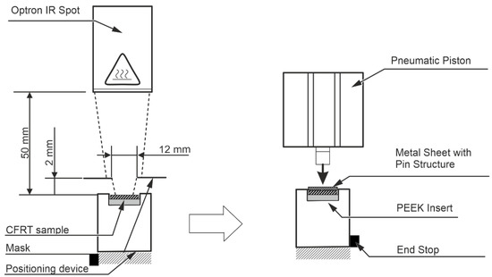
Figure 3.
Schematic illustration of the joining device.
The joining process is conducted in the following three steps:
First, the sample is placed in the positioning device and is heated in such way, that the matrix is molten through the entire thickness of the sample. The heating parameters have been identified in previous investigations [16] and are directly taken over.
Second, the positioning tool is placed under the pneumatic piston and the metal component is placed on top of the CFRT sample while a form-fit in the positioning device allows proper concentrical alignment of the pin structure with the heated zone in the CFRT component. Detailed measurements of the samples used can be seen in Figure 4.
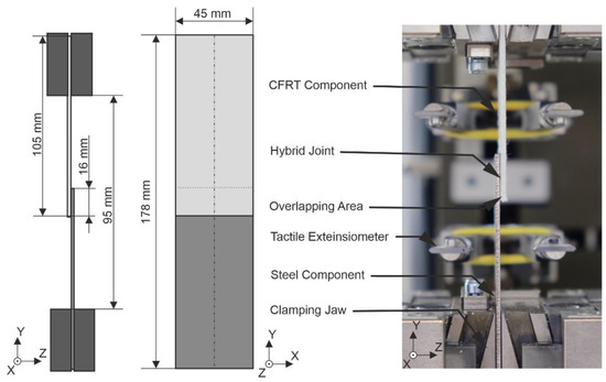
Figure 4.
Sample dimensions and test setup for single lap shear tests.
Third, the pin is pressed into the CFRT component via the pneumatic piston. During the cooling stage, the pressure remains applied onto sample, to allow a complete reconsolidation of the laminate. After the cooling stage, which was defined to approximately 60 s in this study, the pressure is removed and the joined sample is removed from the positioning device.
The heating as well as joining parameters in this study were identical with the settings in [16], where a good reconsolidation quality without matrix damage due to overheating could be achieved. The settings are summarized in Table 2.

Table 2.
Used heating and joining parameters.
2.5. Mechanical Characterization—Single Lap Shear Test
The joined specimen were mechanically tested using the single lap shear test according to the technical bulletin DVF EFB 3480-1 [17]. Both components of the hybrid sample had a length of 105 mm and a width of 45 mm; the joining position was placed 8 mm from the short side of the samples, resulting in an overlap of 16 mm and a total length of the hybrid sample of 178 mm. The clamping free length measured 95 mm. The elongation of the sample was measured via tactile extensometers with a measuring distance of 50 mm. The test setup and sample dimensions are summarized in Figure 4.
Before testing, the samples were stored in normalized climate (23/50) according to DIN EN ISO 291 [18]. The test was performed on a universal testing machine type Z1465 from ZwickRoell AG (Ulm, Germany) in quasi-static condition with a testing speed of 1 mm/s and a sampling rate of 100 Hz.
In the scope of this study, 10 different variations were investigated consisting of a variation in the non-rotational-symmetric pin geometries’ orientation in relation to the load direction and a variation in the fiber orientation in relation to the load direction. The sample size of each parameter setting was n = 3 resulting in 30 tested samples. Thereby, the two investigated orientations of the elliptical pin were named “0°” and “90°”, which correspond to the orientation of the long axis of the pin in relation to the load direction. The investigated pin orientations of the polygonal pin are described as “sharp” and “blunt”, which distinguishes whether the edge or the side of the triangular geometry transmit the force between both joining partners in the single lap shear test. A variation in the orientation of the cylindrical pin was not possible due to the rotational symmetric shape. Table 3 summarizes the conducted variations. The fiber orientation is described to 0° and 90°, which corresponds to the fiber orientation in relation to the load direction.

Table 3.
Summary of the conducted variations for the mechanical characterization.
2.6. Microscopic Investigation
In order to create an understanding about the failure behavior of the joint, microscopic investigations of the CFRT and metal component after failure were conducted. For this, a stereo microscope type Discovery V12 and a microscopy camera of the type Axio Cam MRc5 (both Carl Zeiss Microscopy GmbH, Jena, Germany) were used. The images were created so that the X/Y plane could be analyzed in detail (compare Figure 4). In order to create a sufficient depth of focus and to be able to analyze sections of the samples with different elevations, multiple single images with different focus distances were stacked to one image. Before investigation, the metal and CFRT components were separated and were investigated individually. Of each variation, one CFRT component and one metal component were investigated. Thus, the samples, which showed the highest maximum forces of each variation, were chosen for the microscopic investigation. To create a better understanding about the initial failure behavior under shear load, two cylindrical samples with fiber orientations in 0° and 90° were tested in the above-described procedure until a first drop in reaction force could be seen. After this initial drop in the reaction force, the testing procedure was manually terminated and the samples were examined in the same manner as described above.
3. Results
3.1. Pin Manufacturing Process
To gain a deeper understanding of the pin extrusion process, especially for non-rotationally symmetrical geometries, to verify the repeatability during extrusion and to investigate the extrusion process in more detail, the force–displacement data of the pin extrusion process were analyzed. Figure 5 shows the punch force–displacement curves averaged from four experiments for each of the pin geometries investigated. Furthermore, the standard deviation of the respective geometries is shown using an error band. Here, it can be seen that the standard deviation with a maximum value of ±0.13 kN across all the investigated geometries is very low compared to the maximum forces between 18.23 kN for the elliptical 0° pins and 21.74 kN for the cylindrical pins.
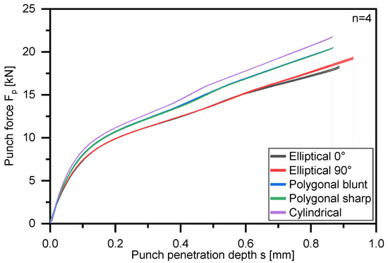
Figure 5.
Punch force Fp to punch penetration depth s for the different pin geometries and different orientations. The curves are the average from four tests and the standard deviation is shown using error bands.
Comparing the maximum standard deviation of the different pin geometries, the cylindrical and polygonal blunt pins show the smallest deviations with ±0.08 kN. In contrast, the deviation of the other geometries with ±0.12 kN (polygonal sharp), ±0.13 kN (elliptical 0°) and ±0.13 kN (elliptical 90°) are on a slightly higher level. If we compare the force–displacement curves of the geometries formed in different orientations, i.e., the polygonal sharp and blunt as well as the elliptical 0° and 90°, we see that the rotation of the polygonal geometry has only a very slight influence on the forming and thus the force–displacement curve, and thus the curves are almost identically superimposed. This can be explained by the fact that the general orientation of the geometry in relation to the rolling direction of the sheet does not change and thus similar forming conditions are present. Conversely, a comparison of the elliptical pins at 0° and 90° shows a deviation in the force starting at a punch penetration depth of around 0.6 mm. Here, the slope of the force–displacement curve is greater for the elliptical 90° pins than for the elliptical 0° pins. In this case, the rolling direction during cold rolling and thus the orientation of the grains of the sheets used for the extrusion of the pin structures is along the long axis of the ellipse in 0° and therefore along the short axis for the ellipse in 90°. Consequently, it is possible that for the 90° ellipses along the short side, a greater number of linear dislocations are necessary for the pin extrusion. However, this effect can only be detected as the punch penetration depth increases, as can be seen from Figure 5, since at the beginning of extrusion, the radial flow of material outward into the sheet plane is initially more dominant, and this is directionally independent [19]. The smaller the residual sheet thickness, the more dominant the extrusion into the die, and here the directional dependence due to the pin geometry can be detected.
In Table 4, in addition to the force–displacement curves shown in Figure 4 and Figure 5, the corresponding pin height, punch penetration depth, sheet thickness, relative punch penetration depth and residual sheet thickness averaged from a sample of n = 4 pins are listed for the different investigated pin geometries. Looking at the force–displacement curves shown in Figure 5 and the associated standard deviations, as well as the parameters relevant for pin extrusion shown in Table 4 and the respective standard deviations, it can be seen that both the process and the resulting pin structures can be assumed to be repeatable.

Table 4.
Pin height h, punch penetration depth s, sheet thickness, relative punch penetration depth in relation to initial sheet thickness and residual sheet thickness for the investigated and extruded pin geometries (n = 4).
When considering the pin heights and the required punch penetration depths, it can be seen that, compared to polygonal and cylindrical pins, the elliptical pin structures require a greater penetration depth. This effect has already been demonstrated in [15] and it could be shown that with an increasing pin cross-sectional area compared to the punch cross-sectional area, it leads to a greater material utilization of the material displaced by the punch, since the reduction in the flow resistance into the die reduces the radial material flow into the sheet plane and increases the axial material flow into the die. However, due to the larger cross-sectional area, a larger volume of material is required to achieve the same pin height as in the other pin geometries with smaller cross-sectional areas. This larger volume of material is not entirely compensated for by the increase in material utilization, which is why a greater punch penetration depth is necessary for the elliptical pins [15]. A comparison of the punch penetration depths of the elliptical 0° and 90° pins shows it is noticeable that the elliptical 90° pins have a greater punch penetration depth than the elliptical 0° pins. However, these also have a greater pin height of 1.82 mm on average compared to 1.78 mm. Thus, less material was displaced from the punch with the elliptical 0° pins, which can result in the lower average pin height. However, the orientation of the geometry to the rolling direction may also have a certain influence on the punch penetration depth and the corresponding pin height cannot be conclusively clarified based on the present results, since the penetration depths are not identical. However, an influence can be suspected, since due to the higher force requirement, which results from the orientation of the geometry and thus represents a greater flow resistance, the amount of radial material flow increases compared to the elliptical 0° pins. This would result in a greater punch penetration depth being required for the elliptical 90° pins to achieve the same pin height as the elliptical 0° pins.
3.2. Mechanical Characterization
As it can be expected, the results from the single lap shear tests show a strong dependency on the pin type and pin-orientation as well as the fiber orientation in relation to the load direction. For all pin types and pin orientations, it can be seen that a significant increase in the maximum force comes with a fiber orientation of 90°. Table 5 and Figure 6 give a summary of the measured maximum forces in the single lap shear test.

Table 5.
Summary of maximum shear force results.
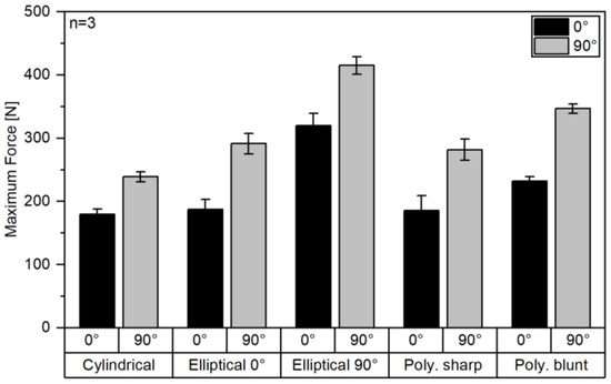
Figure 6.
Maximum force in single lap shear tests.
Therefore, the increase in force between fibers in 0° and 90° lies between 33.3% for the cylindrical pins and 55.4% for elliptical pins with an orientation of 0° in relation to the load direction. It is noticeable that the non-rotational symmetric pins lead to increased maximum forces in comparison to cylindrical pins independently on the pin- and fiber orientation. However, the increase in maximum force for an elliptical pin 0°/0° and the polygonal sharp/0° pin compared to a cylindrical 0° pin is relatively low with only 4.6% and 3.3%, respectively, in comparison to the corresponding cylindrical pins tested with the same fiber orientation.
When comparing elliptical pins with different orientation, it shows that a 90° pin orientation leads to an increase in maximum force of 70.5% (0° fiber orientation) and 73.6% (90° fiber orientation), which leads to the conclusion that for elliptical pins in CFRT/metal joining, an orientation of the pin in 0° to the load direction is strongly inferior in comparison to a pin orientation of 90°. When comparing this result with Römisch et al. [15], where a material combination of a DP600 and aluminum EN AW-6014 was investigated, this finding is contrary. Römisch et al. found an increased joint strength under shear load, when the pin was oriented in 0° of 878 ± 7 N in comparison to 811 ± 9 N with a pin oriented in 90° while in both cases the failure occurred due to a broken-off pin structure. This is explained with a higher area moment of resistance of the pin of 0.39 mm3 in 0° in comparison to 0.2 mm3 in 90°, which leads to pin failure at higher loads when the pin is oriented in 0°. In the present study, however, the joint did not fail due to pin breakage and consequently other mechanisms were found (compare Section 3.3). For polygonal pins, it shows that a “blunt” orientation in relation to the load direction is superior in means of maximum transmitted force with an increase of 25.2% (0° fiber orientation) and 23.1% (90° fiber orientation) in comparison to the “sharp” orientation.
When analyzing the foot print related joint strength, which can be seen as an indication for the efficiency of a certain pin geometry, especially with the perspective of multi-pin joints, which will be required to achieve higher total joint stabilities, a different situation shows. The baseline joint strength of the cylindrical pins is 227.0 ± 11.1 MPa and 302.5 ± 10.2 MPa, respectively, for fiber orientations in 0° and 90°. Table 6 and Figure 7 summarize the resulting foot print related joint strength.

Table 6.
Summary of joint strength results.
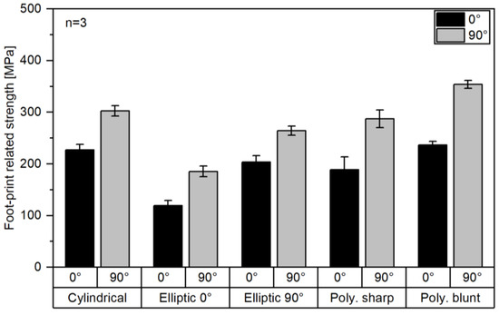
Figure 7.
Foot print related strength in single lap shear tests.
Elliptical pins show reduced joint strength when compared to cylindrical pins. This phenomenon is most pronounced for elliptical 0°/0° samples where a joint strength of only 119.4 ± 9.9 MPa is measured, which is a decrease of 107.6 MPa or 47.4% when compared to cylindrical 0° samples. For elliptical 0°/90° pins, the drop in joint strength is in a similar range with 116.9 MPa or 38.6%. Elliptical pins with an orientation of 90°/0° and 90°/90° perform better but still lead to a reduction of 23.4 MPa (0° fiber orientation) and 38.2 MPa (90° fiber orientation) respectively.
In contrast to elliptical pins, polygonal pins lead to either increased or decreased foot print related joint strength, depending on the pin-orientation. While pins with “sharp” orientation lead to a reduction in joint strength of 37.9 MPa/16.7% (0° fiber orientation) and 15.1 MPa/5.0% (90° fiber orientation), respectively, an increase by 9.7 MPa/4.3% (0° fiber orientation) and 51.2 MPa/16.9% can be seen for polygonal pins with a “blunt” pin orientation in relation to the load direction. Generally, it can be summarized that from a joint strength perspective, an elliptical pin is disadvantageous, especially when oriented in the load direction while a polygonal pin can be beneficial when oriented so that the blunt side introduces the load into the CFRT component but is disadvantageous when the sharp edge is oriented towards the interfacing surface.
When comparing the joint strength in relation of the projection area of the pin geometries in the direction of the testing load, it shows that, especially with fiber orientations of 0°, the measured values are in a comparable range between 87.0–103 MPa (compare Figure 8 and Table 7). This can be explained with the dominant failure behavior of these samples (compare Section 3.3 and Table 8), which for fiber orientations of 0°, typically is a failure of the CFRT component, which occurs at similar compressive stresses induced into the CFRT laminate. The lowest projection related strength is measured for elliptic 90°/0° pins, which show a combination of CFRT failure and subsequent pin extraction, which can be assumed as the reason for the reduced strength.
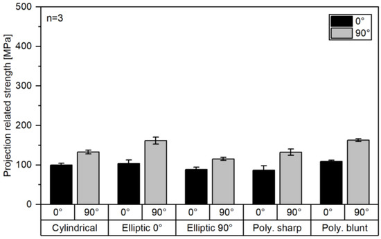
Figure 8.
Projection area related strength in single lap shear test.

Table 7.
Summary of projection area related joint strength.

Table 8.
Summary of failure modes.
With 90° fiber orientation, the values vary between 115.3 and 162.8 MPa, which is a significantly higher range. This higher fluctuation can be explained with two approaches: first, more diverse failure modes (both pin extraction and CFRT failure occur); second, for samples with a failure due to pin extraction, the area moment of resistance of the pin structure strongly varies leading to pin bending and subsequent pin extraction at different loads. So consequently, elliptical 0°/0° pins have a significantly increased strength in comparison to cylindrical 0° pins as it has a higher area moment of resistance with the same projection area as the cylindrical pin avoiding the failure due to pin extraction, and consequently, failure at higher loads but with the same projection area leading to higher projection are related joint strength.
Figure 9 summarizes the force–displacement curves of all tested samples in dependency of pin type, pin orientation and fiber orientation. Therefore, curves with dotted lines represent samples with a 90° fiber orientation while solid lines represent 0° fiber orientation. Generally, it can be seen that a fiber orientation of 90° leads to higher maximum forces and typically to a more abrupt drop in reaction force after the maximum force is reached. The exceptions to this phenomenon are elliptical 0°/90° and polygonal sharp/90° pins, where the reduction in reaction force is relatively smooth as it is the case for their 0° fiber orientation counter parts but with the distinction of higher force levels. A possible explanation for this behavior is that these pin samples have a comparably high resistance against pin bending, which avoids pin deflection and consequent pin extraction but are shaped in such way that the force is introduced into the CFRT sample over a relatively small and sharp edge. This leads to concentrations of tension and following gradual failure of the fibers in the CFRT component, leading to a less abrupt failure (compare Section 3.3). Another interesting phenomenon is that the force–displacement curves of cylindrical 0° and elliptical 0°/0° samples are very similar and that the measured average maximum forces are identical in the range of the standard deviation. This can be explained with the failure behavior that is for both samples a failure of the CFRT sample and no deformation of the pin structure (compare Section 3.3). As the projected area of both pin types in the direction of force application is identical, similar pressure is introduced into the CFRT component by the pin and consequently, the maximum force before failure of the CFRT in both sample types is almost identical.
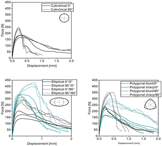
Figure 9.
Force–displacement curves for cylindrical (top), elliptical (bottom left) and polygonal pins (bottom right).
For all samples, with the exception of elliptical 90°/90° samples, it can be seen that the initial stiffness of sample pairs with 0° and 90° fiber orientation are very similar, but that the force–displacement curves of samples with 0° fiber orientation flattens, indicating a reduction in stiffness, before reaching the maximum force level while a 90° fiber orientation typically leads to a steeper curve until the maximum force is reached. In combination with the typically more abrupt drop in force with 90° degree fiber orientation, it is concluded that in the course of this study with non-undercutting pin geometries, 0°-degree fiber orientation leads to a less critical failure behavior than a fiber orientation of 90°, but at lower absolute force levels.
The comparison of the mechanical performance in the present study with studies in the literature which deal with pin based CFRT/metal joining is not easily achievable. Reasons for this are the use of different CFRT [14] or metal [20] components as well as divergent pin manufacturing methods [21]. When comparing with Kraus et al. [14], where a maximum force of 118 N was reached with a pin diameter of 1.32 mm and a pin height of 1.48 mm, both the maximum force as well as the foot print related joint strength in the present study are higher. This could possibly be explained with the lower pin height of the samples, which leads to early pin extraction as well as a different sample geometry. In [20], a pin-array with 16 pins was tested with a maximum reaction force under shear load of 5570 N and consequently a maximum force per pin of 348 N. This is higher than the values in the present study, but only partially comparable. First, the thickness of the CFRT component is significantly higher with 4 mm, potentially leading to higher reaction forces. Second, the sample geometry is fundamentally different and avoids pin extraction due to bending of the single lap shear sample, which could also lead to increased reaction forces. Finally, the exact pin geometry was not presented in [20], which makes it difficult to assess the performance based on the foot print.
Generally, the presented mechanical performance was relatively good, when compared to other studies, but it has to be acknowledged, that the comparability is limited [14,20,21]. Therefore, in future studies it is required to investigate pin-arrays which on one hand increase the general load capacity of the joint but also allow to relate the maximum forces with the actual joint surface to obtain comparable joint strength values, which also allows to relate the results with established joining technologies such as adhesive joining or arrays of bolts and rivets.
3.3. Failure Analyzation
In the following section, the observed failure behavior of the samples is described and first explanations for the underlying failure mechanisms are given. In the course of this study, two distinct failure modes occurred depending on the fiber orientation in the CFRT component and the type and orientation of the pin geometry in relation to the load direction. The study shows that with a fiber orientation of 0°, the samples tend to fail due to failure of the CFRT component while with fibers oriented in 90°, the samples more often fail due to an extraction of the pin structure at higher loads, as was also found in [13].
Figure 10 shows images of samples created after manually stopping the single lap shear test after the initial drop of force was noticed. On the left, an example of a sample with 90° fiber orientation and a cylindrical pin is shown with a clearly visible separation between the CFRT and metal component which is a sign for beginning pin extraction and also a significant bending of the CFRT sample, which is a result of the samples’ low bending stiffness perpendicular to the fiber orientation and the resulting rotary moment induced by the testing forces. In the middle, a microscopic image of an exemplary CFRT sample with a 90° fiber orientation after the extraction of the steel component is shown, which shows no significant deformation of the pin hole. Despite the lack of hole-deformation, dark areas can be seen below the pin hole that is the area where the testing forces are introduced into the laminate, which can be interpreted as matrix cracks due to the introduced compressive stress perpendicular to the fiber orientation. These cracks are a result of the unidirectional composite’s low strength under compressive loads perpendicular to the load direction. However, despite the low compressive strength perpendicular to the load direction, samples loaded in 90° to the fiber orientation still show higher maximum forces before failure of the joint, which needs further explanation. This can be explained by the more efficient introductions of the testing load into the fibers in comparison to 0° fiber orientation. In 90°, the fibers take up the testing load similar to an arresting cable used at aircraft carriers to rapidly decelerate landing airplanes and translate the testing load into a tensile load in the fibers.
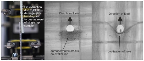
Figure 10.
Summary sample behavior directly after maximum force: single lap shear sample with fiber orientation in 90° to load direction (left), CFRT component with removed cylindrical pin (fiber orientation: 90°, (middle)) and CFRT component with ovalized pin hole (fiber orientation: 0°, (right)).
On the right, a sample with fibers in 0° orientation is shown. This sample clearly shows an ovalization of the pin hole as a result of the introduced compressive stresses. An explanation for this deformation can be found in the distinct fiber morphology, which occurs, in the direct pin pressing process (compare [8]) which leads to practically fiber free, matrix rich zones, which are located next to the pin hole in the direction of fibers. When samples are loaded in 0° to the fiber orientation, the testing force is directly introduced into these matrix rich zones, which have no reinforcing fibers and consequently are less stiff leading to the shown ovalization of the pin-hole and to a reduction in force in the mechanical tests.
Table 8 summarizes the observed failure modes. A tendency for failure of the CFRT component with 0° fiber orientation and pin extraction failure with 90° fiber orientation can be seen, which also corresponds with the findings in the previous section.
Exceptions to this are elliptical 0°/90° and polynomial blunt/90° samples, which also showed divergent force–displacement curves in Figure 9. This can be explained by the comparably sharp edge of the pin structure at the point of load transmission in combination with a pin geometry, which has an increased resistance against pin bending and consequently less likely pin extraction. This leads to a failure of the CFRT component where the fibers are cut perpendicular to the fiber orientation. In Figure 11, a summary of microscopic images after failure of the sample is shown. It can be clearly seen that samples that failed with pin extraction are significantly less damaged than samples that failed due to CFRT failure. Furthermore, the elliptical 0°/90° and polygonal sharp/90° example clearly show a CFRT failure with cut fibers in the direction of load.
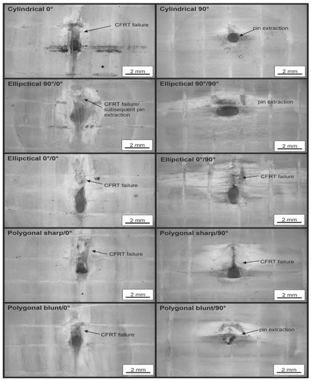
Figure 11.
Summary of CFRT samples after single lap shear test.
One factor that amplifies the tendency for pin extraction is that pins tested with 90° fiber orientation bend due to the higher testing forces in comparison to 0° fiber orientation. This force in combination with the comparably soft CFRT component, which does not provide significant support against bending, leads to the pin plastically deflecting under load. Figure 12 shows cylindrical and polygonal pins after failure. It can be clearly seen that pins with a 90° fiber orientation strongly deflect in the direction of testing while pins tested with a 0° fiber orientation are not or significantly less deformed. In comparison to the shown images, elliptical 90°/90° pins are similarly deformed while polygonal sharp/90° pins and elliptical 90°/0° pins show a strongly reduced deformation. Elliptical 0°/90° as well as 0°/0° and polygonal sharp/0° pins do not show a significant deformation. Pins tested with fiber orientation in 0° generally did not significantly deform.
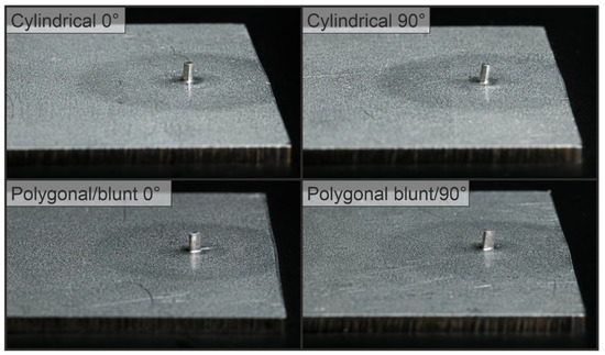
Figure 12.
Cylindrical and polygonal blunt pins with fiber orientations of 0° and 90° after testing.
The shown deformation of the pin structure corresponds with the earlier described failure phenomena. Pins of samples with failure due to pin extraction are strongly deformed while samples with CFRT failure typically show only slightly deformed pins. The shown deflection leads to a changed flux of force during experimental testing with a resulting force component that facilitates the pin extraction and ultimately leads to a slipping of the pin from the joint and consequent joint failure. A possible way to counteract this tendency for pin extraction is the use of undercutting pin geometries, which interlock in the CFRT component and consequently counteract a pin extraction. This was already shown by Ucsnik et al. in [20] where in the field of metal/epoxy based composite joining, interlocking pin geometries with ball heads lead to 37.4% higher maximum forces in a double lap shear test.
4. Summary
In the scope of this study, it could be shown that in the field of direct pin pressing of cold formed pin structures into locally heated CFRTs, an increase in maximum force before failure can be achieved with non-rotational symmetric pins in comparison to the investigated cylindrical reference pin. The maximum transmittable force depends strongly on the factors of fiber orientation and pin orientation in relation to the load direction as well as the tested pin geometry. Therefore, elliptical pins and fibers both oriented in 90° to the load direction show the highest average maximum force with 415.0 ± 13.6 N. However, when relating the maximum force to the foot print of the pin structure as an indication for the efficiency of a pin structure, it shows that elliptical pins are inferior to cylindrical pins and that polygonal pin structures are, in dependency of the pin orientation, either slightly superior or slightly inferior to cylindrical pins.
Investigation of the failed samples shows that two distinct failure modes occur:
Failure of the CFRT component, which typically occurs when a sample with a fiber orientation in 0° is tested or when pins with a sharp edge such as elliptical pins with a 0° orientation or polygonal pins in the “sharp” orientation are combined with a fiber orientation of 90° leading to cut fibers.
Pin bending and subsequent pin extraction, which occurs at higher loads than CFRT failure, which are sufficient to deform the pin structure. This failure typically occurs with fiber orientations of 90°, which leads to a more efficient force introduction into the reinforcing fibers as the fibers are oriented perpendicular to the introduced load and support the introduced load similar to an arresting cable in naval aviation.
5. Conclusions
Based on the findings in this study, the selection of a certain pin structure must be made based on the expected loads in the use case of the hybrid parts. If an isotropic behavior of the joint is required, cylindrical pin structures seem favorable; if a main direction of load is expected, a polygonal pin with specifically chosen orientation could be beneficial. Thus, the findings of this work enable the design of customized joints adapted to the application with the aid of adapted pin geometries and orientations, which increases the versatility of the joining process.
Furthermore, a more detailed investigation of the pin extrusion of non-rotationally symmetrical geometries based on the different orientation of the elliptical pin structures has shown that the orientation in relation to the rolling direction of the blank has an influence on the required forming force, which can consequently affect the work hardening of the pin structure.
In future studies, it is necessary to investigate multi-pin arrays in order to increase the maximum transmittable forces. Therefore, it is required to determine minimum pin spacing in dependency of the pin’s dimensions, fiber orientations and restrictions from a pin manufacturing standpoint. In addition, the effect of the orientation of non-rotationally symmetric pin geometries on the strain hardening of the pin structures should be investigated in future work, since strain hardening of the pin structure, especially in the pin base, plays a crucial role in the subsequent shear strength of the joint. In addition, the production of undercutting pin geometries via cold extrusion requires further studies, as it is expected that undercuts can increase the joint strength under shear loads, especially with a fiber orientation of 90°, where pin extraction is the dominant failure mode, which could be counteracted with an undercutting pin. Furthermore, future studies are planned to investigate different laminate structures, such as bi-axial laminates.
Author Contributions
Conceptualization, J.P.; methodology, J.P. and D.R.; formal analysis, J.P. and D.R.; investigation, J.P. and D.R.; resources, D.D. and M.M.; writing—original draft preparation, J.P. and D.R.; writing—review and editing, J.P., D.R., D.D. and M.M.; visualization, J.P. and D.R.; supervision, D.D. and M.M.; project administration, D.D. and M.M.; funding acquisition, D.D. and M.M. All authors have read and agreed to the published version of the manuscript.
Funding
This work was funded by the Deutsche Forschungsgemeinschaft (DFG, German ResearchFoundation)-TRR 285 C01-Project-ID 418701707. We acknowledge financial support by Deutsche Forschungsgemeinschaft and Friedrich-Alexander-Universität Erlangen-Nürnberg within the funding programme “Open Access Publication Funding”.
Institutional Review Board Statement
Not applicable.
Informed Consent Statement
Not applicable.
Data Availability Statement
All relevant data is represented in this publication. Data sharing is not applicable to this article.
Conflicts of Interest
The authors declare no conflict of interest. The funders had no role in the design of the study; in the collection, analyses, or interpretation of data; in the writing of the manuscript, or in the decision to publish the results.
References
- Siebenpfeiffer, W. Leichtbau-Technologien im Automobilbau: ATZ/MTZ-Fachbuch, 1; Springer Vieweg: Wiesbaden, Germany, 2014. [Google Scholar]
- Barkoula, N.-M.; Karger-Kocsis, J. Effects of fibre content and relative fibre-orientation on the solid particle erosion of GF/PP composites. Wear 2002, 252, 80–87. [Google Scholar] [CrossRef]
- Martinsen, K.; Hu, S.J.; Carlson, B.E. Joining of dissimilar materials. CIRP Ann.—Manuf. Technol. 2015, 64, 696–699. [Google Scholar] [CrossRef] [Green Version]
- Dawai, Z.; Qi, Z.; Xiaoguang, F.; Shengdung, Z. Review on Joining Process of Carbon Fiber Reinforced Polymer and Metal: Methods and Joining Process. Rare Met. Mater. Eng. 2018, 47, 3686–3696. [Google Scholar] [CrossRef]
- Mitschang, P.; Velthuis, R.; Rudolf, R. Fügeverfahren für FKV. In Handbuch Verbundwerkstoffe, 2nd ed.; Neitzel, M., Mitschang, P., Eds.; Carl Hanser: München, Germany; Wien, Autria, 2014; pp. 469–482. [Google Scholar]
- Schürmann, H. Klebeverbindungen. In Konstruieren mit Faser-Kunststoff-Verbunden; Springer: Berlin/Heidelberg, Germany, 2005; pp. 569–604. [Google Scholar]
- Brockmann, W. Adhesive Bonding of Polypropylene. In Polypropylene: An A–Z Reference; Karger-Kocsis, J., Ed.; Kluwer: London, UK, 1999; pp. 1–6. [Google Scholar]
- Popp, J.; Kleffel, T.; Römisch, D.; Papke, T.; Merklein, M.; Drummer, D. Fiber orientation Mechanism of Continuous Fiber Reinforced Thermoplastic Hybrid Parts Joined with Metallic Pins. Appl. Compos. Mater. 2021, 28, 951–972. [Google Scholar] [CrossRef]
- Eberl, L.; Avila Gray, L.; Zaremba, S.; Drechsler, K. The effect of fiber undulation on the strain field for pinned composite/titanium joints under tension. Compos. Part A 2017, 103, 148–160. [Google Scholar] [CrossRef]
- Ucsnik, S.; Scheerer, M.; Zaremba, S.; Pahr, D.H. Experimental investigation of a novel hybrid metal-composite joining technology. Compos. Part A 2010, 41, 369–374. [Google Scholar] [CrossRef]
- Graham, D.P.; Rezai, A.; Baker, D.; Smith, P.A.; Watts, J.F. A Hybrid Joining Scheme for High Strength Multi-Material Joints. In Proceedings of the 18th International Conference on Composite Materials, Jeju, Korea, 21–26 August 2011. [Google Scholar]
- Parkes, P.N.; Butler, R.; Meyer, J.; de Oliveria, A. Static strength of metal-composite joints with penetrative reinforcement. Compos. Struct. 2014, 118, 250–256. [Google Scholar] [CrossRef] [Green Version]
- Popp, J.; Kleffel, T.; Drummer, D. Influence of pin geometry on the joint strength of CFRT-metal hybrid parts with metallic pins. Join. Plast. Fügen Kunstst. 2021, 3, 177–183. [Google Scholar]
- Kraus, M.; Frey, P.; Kleffel, T.; Drummer, D.; Merklein, M. Mechanical joining without auxiliary element by cold formed pins for multi-material-systems. AIP Conf. Proc. 2019, 2113, 050006. [Google Scholar]
- Römisch, D.; Kraus, M.; Merklein, M. Investigation of the influence of formed, non-rotationally symmetrical pin geometries and their effect on the joint quality of steel and aluminium sheets by direct pin pressing. Proc. Inst. Mech. Eng. Part L J. Mater. Des. Appl. 2022. [Google Scholar] [CrossRef]
- Popp, J.; Drummer, D. Joining of continuous fiber reinforced thermoplastics/steel hybrid parts via undercutting pin geometries and infrared heating. J. Adv. Join. Process. 2022, 5, 100084. [Google Scholar] [CrossRef]
- Deutscher Verband für Schweißen und Verwandte Verfahren. DVS/EFB 3480-1 Testing of Properties of Joints—Testing of Properties of Mechanical and Hybrid (Mechanical/Bonded) Joints; DVS Media GmbH: Düsseldorf, Germany; Beuth Verlag GmbH: Berlin, Germany, 2007. [Google Scholar]
- DIN e.V. DIN EN ISO 219:2008; Plastics-Standard Atmospheres for Conditioning and Testing. Deutsches Institute für Normung: Berlin, Germany, 2008.
- Ghassemali, E.; Tan, M.J.; Jarfors, A.; Lim, S. Progressive microforming process: Towards the mass production of micro-parts using sheet metal. Int. J. Adv. Manuf. Technol. 2013, 66, 611–621. [Google Scholar] [CrossRef]
- Thakkar, R.; Ucsnik, S. Cost Efficient Metal to Fibre Reinforced Composite Joining. In Proceedings of the ECCM16—16th European Conference on Composite Materials, Seville, Spain, 22–26 June 2014. [Google Scholar]
- Feistauer, E.E.; Guimaraes, R.P.M.; Ebel, T.; dos Santos, J.F.; Amancio-Filho, S.T. Ultrasonic joining: A novel direct-assembly technique for metal-composite hybrid structures. Mater. Lett. 2016, 170, 1–4. [Google Scholar] [CrossRef]
Publisher’s Note: MDPI stays neutral with regard to jurisdictional claims in published maps and institutional affiliations. |
© 2022 by the authors. Licensee MDPI, Basel, Switzerland. This article is an open access article distributed under the terms and conditions of the Creative Commons Attribution (CC BY) license (https://creativecommons.org/licenses/by/4.0/).