1. Introduction
With the characteristics of excellent mechanical properties, outstanding weldability and good hot workability, Q235 steel has widely and successfully been adopted in the high-voltage transmission tower, bridge, automotive, container and shipbuilding industries [
1,
2,
3]. Q235 steel is a common carbon structural steel with moderate carbon content and a tensile strength that reaches 370–500 MPa. Fusion welding is the most common and effective welding method for structural steel connections [
4,
5].
Typical arc welding processes such as gas metal arc welding (GMAW) and gas tungsten arc welding (GTAW) are found in abundance in the industry, but due to low power density, higher welding speeds are not possible. Hence, arc welding processes usually have a higher heat input which gives rise to a large number of distortions. On the contrary, laser welding, being a high power density heat source, can produce weld joints with larger depth to width ratios [
6,
7,
8]. Additionally, high-quality joints can be obtained with a laser because of the short-acting time, higher welding speed, higher efficiency and minimal distortions [
9,
10]. However, laser welding still has some shortcomings such as poor gap bridgeability, higher reflectivity (especially at larger wavelengths), high equipment costs and prone to produce cracks and pores in the welded joint [
11]. Laser-arc hybrid welding combines laser and arc heat sources to make up for their individual shortcomings [
12,
13,
14]. Thus, laser-arc hybrid welding has the merits of a large welding penetration depth, high process stability, high welding efficiency, lower heat input, a wide range of weldable materials and small welding deformation which is a potential development direction for Q235 plate welding [
15,
16,
17].
X. N. Wang [
18] used a hybrid fiber arc laser welding (HFAL) process to study a new 8 mm thick hot-rolled Nb-Ti-Mo micro-alloyed steel. The results showed that with the increase of heat input, the martensite content decreased, but the granular bainite (GB) content increased for the microstructure components. C. Roerke and S. Liu [
19] studied the effects of laser and arc power, heat input and preheating on the macrostructure and microstructure of HY-80 steel composite welds. The results reveal that as the heat input increases, the ferrite microstructure increases, and the weld metal microhardness decreases. The research of C. Zhang [
20] shows that the strength enhancement of the fusion zone and heat-affected zone of the LAHW joint are mainly attributed to grains refinement and precipitation strengthening. The arc causes most of the laser energy to be dissipated from the keyhole, so the heat input is reduced. Lower heat input makes the grains size refined, which weakens the over-aging and improves the tensile strength. Y. Q. Zhao [
21] studied the joint microstructure and porosity distribution of 6.9 mm thick 5A06 aluminum alloy plates by laser metal inert gas arc (MIG) hybrid welding. The results show that metallurgical pores are densely populated in the upper area of the weld joint, resulting in obvious joint softening. The formation of pores has a much greater influence on joint softening than grain enlargement. Y. B. Li [
22] compared the MIG welding and laser-MIG hybrid multi-layer welding methods to get a more appropriate method to overcome the poor weldability of the invar36 alloy. The simulation and experimental results were compared, it was proven that the Gauss and cone combined heat source model can characterize the laser-MIG hybrid welding heat source well.
The above discussion reveals that laser-arc hybrid welding technology has been recognized by the welding industry and has great development prospects. Hence, laser- MIG hybrid multi-layer welding (LMHMW) has been used by some large enterprises to replace traditional arc welding for structural steel connection. However, the work of most research groups has been focused on the exploratory process test of LMHMW, which broadens the welding range of hybrid welding but lacks parametric optimization. In this paper, the welding experiment of LMHMW for thick plate Q235 steel is carried out in multiple passes, the microstructure of welded joints is explored, and the effects of heat input on the properties of welded joints are studied.
2. Experimental Materials and Methods
LMHMW with laser leading is schematically demonstrated in
Figure 1. The chemical composition of the base metal and consumable electrode adopted in this investigation are shown in
Table 1 and
Table 2, respectively. A single V groove butt weld in the IG position was employed in the current experiment, and detailed dimensions of joint design are presented in
Figure 2a,b.
The equipment used in this research consists of a TrumpF 12 kW Disk Laser (TruDisk12003) with wavelength 1030 nm and 300 um focused spot diameter. A six-axis KR30 HA Kuka robot with a maximum reach of 2033 mm was coupled with laser welding for automating the whole process. A Fronius multiprocess Transplussynergic (TPS 5000) having a maximum current carrying capacity of 500 Amps was exploited for MIG welding. Inert Argon shielding gas with 99.99% purity level at a 15 L/min flow rate was directed at the common interaction zone of arc and laser heat source.
A total of 5 specimens under varying heat inputs were welded, and the welding process on each 20 mm thick sheet was accomplished in three layers, as elaborated earlier in
Figure 2c. The detailed welding parameters are shown in
Table 3. Heat input can be expressed by the following equation [
23]:
where
E is heat input (KJ/cm),
v is the welding speed (cm/s),
PL and
PA represent the laser and arc power (Watts), respectively.
U and
I denote arc voltage (V) and current (A), respectively.
Oil on the faying surfaces of the base metal was cleaned with acetone. An austenitic stainless steel wire brush was used to remove the oxide layer during interpass cleaning. No preheating or interpass temperature controls were enforced because of the very low carbon equivalent of Q235 steel. After welding, transverse metallography samples were extracted from the specimen to observe interfacial microstructure. Samples were ground and polished using progressively finer abrasive grit, and diamond paste for mirror finishing with subsequent etching in 0.5% nital solution for 8 s. Macroscopic morphology and interfacial microstructure was characterized by an Optical microscope. The microhardness of samples was measured by the Vickers microhardness tester (HVS-50) (Nanjing, China) using a 10 kg load and a dwell period of 15 s. Tensile test samples are prepared by wire EDM and tested on a Universal testing machine (CMT5305), (Shanghai, China), having a maximum capability of 300 kN force.
3. Experimental Results and Discussions
3.1. Joint Macroscopic Morphology and Interfacial Microstructure
The cross-section of the LMHMW welded joint with a typical goblet fusion zone morphology is shown in
Figure 3. There were no hot or cold cracks observed anywhere in the fusion or HAZ, and interpass fusion between the adjacent layers of the weld bead was fairly good. However, there exists some process and metallurgical porosities randomly distributed in different regions of the fusion zone. By observing the macro-morphology of the welded joints, it is found that the weld width increases with the increase of heat input in samples 4 and 5. In addition, obvious root concavity and a lack of penetration were observed in sample 1, which is attributed to relatively higher welding speed. As it is evident from
Figure 3c, sample 3 had maximum weld joint soundness without any indication of undercut, excessive root or face reinforcement. Hence, the welding parameters of sample 3 are the most optimized in terms of macromorphology.
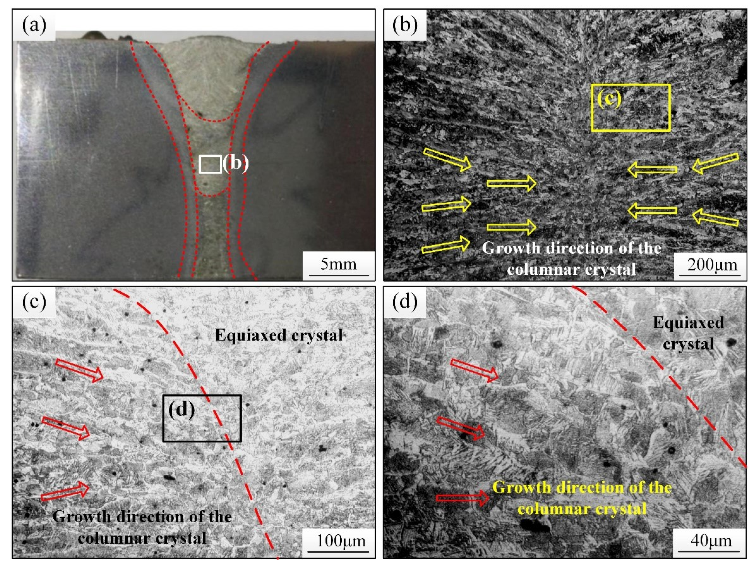
The microstructure of the weld seam (WS) under different magnifications is shown in
Figure 4. The microstructure of the weld is mainly eutectoid ferrite precipitated along the grain boundary of the original austenite and a small amount of ferrite and pearlite with needle and plate-like morphology between the grains. Microstructure morphology in the vicinity of the fusion line is mainly coarse columnar dendrites of proeutectoid ferrite, which grow normal to the fusion line and are aligned in the direction of the maximum temperature gradient. At the weld centre line, a relatively small proportion of equiaxed grains form, which hinders the further growth of columnar crystals. This pattern of microstructural morphology is attributed to constitutional supercooling owing to a difference in the G/R ratio at various positions along the fusion boundary. The weld centre line experiences the least temperature gradient and maximum growth rate, so it is possible that nucleation starts ahead of the columnar dendrites because of a very high amount of constitutional supercooling. However, the orientation of columnar crystals in the vicinity of the base metal (BM) region is not entirely consistent with the orientation of the base metal microstructure, which is caused by the coupling of laser and arc.
Figure 5 exhibit the microstructure of HAZ of welded joints. Depending upon the proximity to the fusion line, HAZ has been categorized into a superheated zone, normalized zone and incomplete recrystallization zone. As can be seen from
Figure 5a, very narrow HAZ was observed because of the synergic effects of the laser and arc. The superheated zone, a narrow region in close proximity to the fusion line, is the area that was heated by weld thermal cycle to temperatures well above the upper critical transformation temperature but just lower than the solidus line in an equilibrium phase diagram, is shown in
Figure 5b. The main microstructure in the superheated zone is a Widmanstatten microstructure with a relatively large grain size because of the fact that austenite grains grow larger in size when they are superheated to temperatures higher than the austenite transformation temperature. At higher cooling rates, which is typical in welding, also bolstered by 20 mm base metal thickness acting as a pseudo-quenching medium that extracts the heat quite rapidly, it is safe to say that time available for the diffusion of carbon atoms is less to nucleate ferrite at grain boundaries. Resultantly, crystals of ferrite form everywhere on the grain and grow in preferred crystallographic directions. The area next to the superheated zone, here defined as normalized zone, is shown in
Figure 5c. Welding thermal cycles caused the temperature to rise beyond the upper critical temperature but not much to cause the bigger austenite grains, as observed earlier. The figure shows the microstructure of the normalized zone and a few superheated zones. In the superheated zone of
Figure 5c, the grain size of the Widmanstatten structure is relatively small because the zone is far from the weld. The microstructure of the normalized zone is fine ferrite and pearlite formed by recrystallization under the influence of the heating and cooling process.
Figure 5d show the microstructures of the incomplete recrystallization zone in which the transformation to austenite was not completed. Compared with the microstructure in the normalized zone, the size of the microstructure in the incomplete recrystallization zone is larger, which is similar in size to that of BM, but its homogeneity is worse relatively.
3.2. Analysis of Joints Microhardness
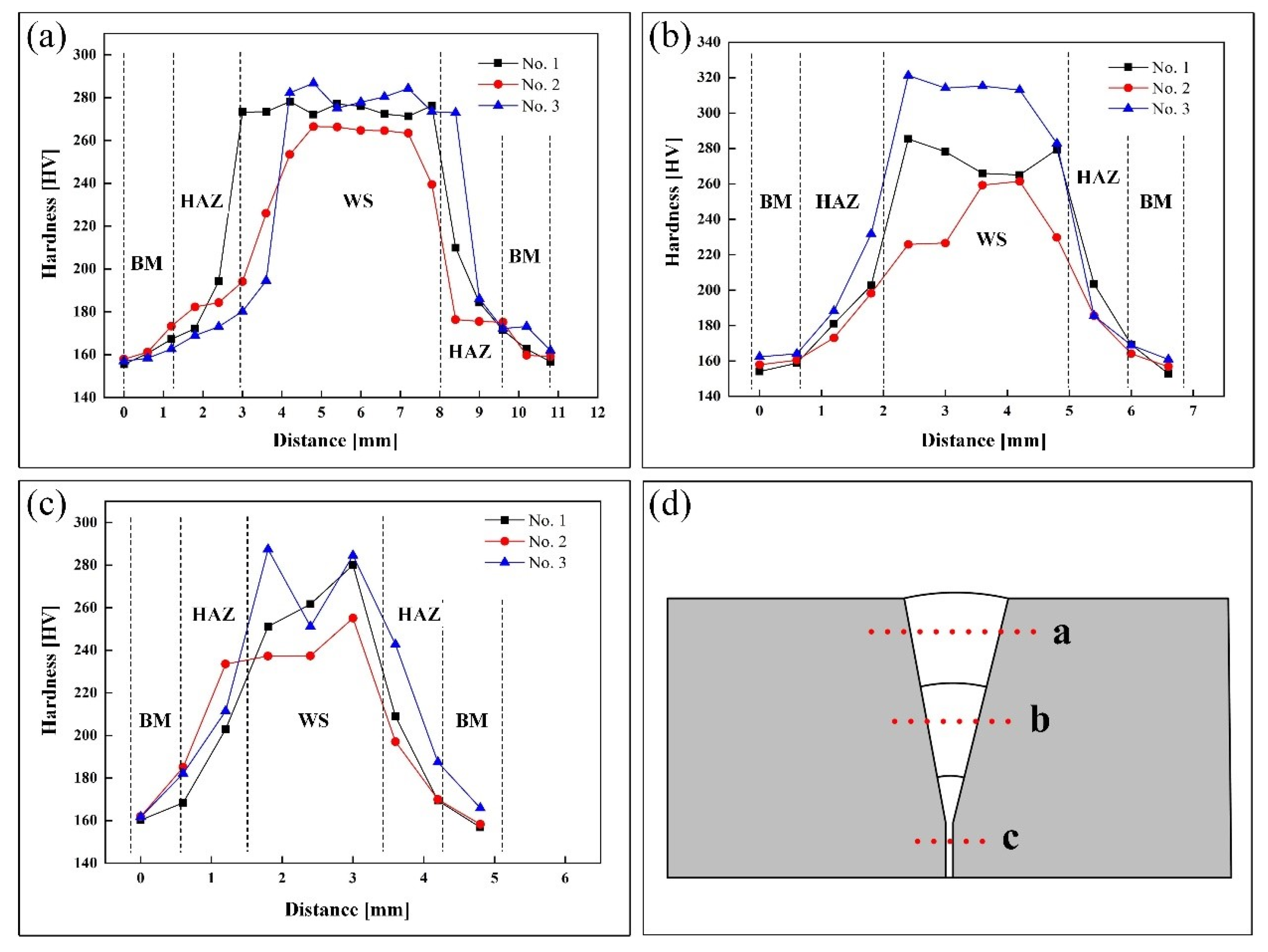
Micro-Vickers hardness testing of each layer was conducted with an interval of 0.6 mm between test points, as shown in
Figure 6.
The microstructure of the BM is equiaxed ferrite and pearlite, whose microhardness is only approximately 158 HV. Due to the formation of potent phases in the normalized and superheated zone, known for arresting the dislocations more effectively as compared to annealed base metal microstructure, the overall trend of higher hardness was observed in the HAZ lying in the range of 160–240 HV as compared to the base metal. The microhardness gradient appears to be very steep in HAZ owing to its narrow width. In addition, different microhardness values were observed at correspondingly silimar locations on each side of the fusion zone because of little variations in microstructure. The microstructure of WS is predominantly plate and needle-like pro-eutectoid ferrite which is relatively uniform; hence there are few variations, but the microhardness of the weld center fluctuates between 260–310 HV because of different heat inputs.
It is evident that the microhardness of the No. 3 sample is the highest, and that of sample 2 is the lowest. As mentioned earlier in the text, from a macro morphological point of view, sample 3 had the most optimum parameters because of the highest weld joint soundness. To investigate this, it is more prudent to analyze the parameters of the cosmetic layer of each sample, because, in other layers, each succeeding layer remelts the preceding layer and causes slight variations in the microstructure as observed in microhardness graphs of filling and backing layers in
Figure 6b,c, respectively. However, a relatively more uniform and stable microstructure exists in the cosmetic layer, as can be observed from the trend in microhardness data shown in
Figure 6a. This can be attributed to the difference in laser to arc power ratio when the heat input is similar. The filling and cosmetic layers of samples No. 1–3 are laid down with the same laser power of 2000 W, but the amperage used is different, as can be noticed from
Table 3. Under the given conditions used in this research, when the MIG amperage in the cosmetic layer is higher or lower than 234 A, the microhardness increases. When the current increases, the heat input increases and the microhardness value is enlarged, whose maximum value can approach 315.9 HV. Generally speaking, the heat input at each position of the No. 3 sample is highest amongst the group; similar results were obtained for microhardness.
3.3. Tensile Test Results
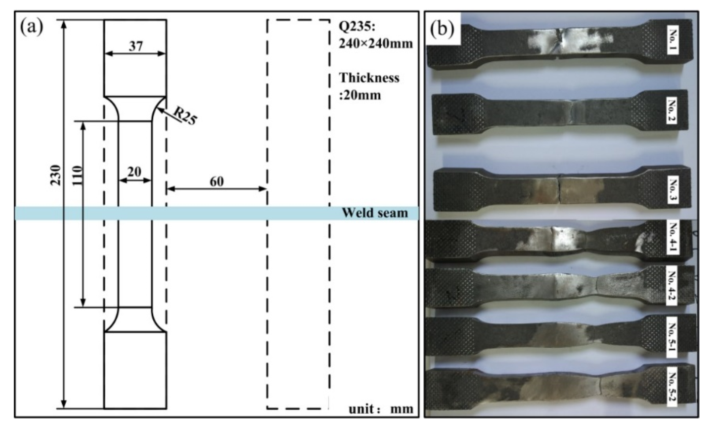
In order to analyze the tensile properties of welded joints for Q235 steel, tensile tests were carried out on samples extracted from each specimen with different process parameters. The specimen design and results of tensile tests are presented in
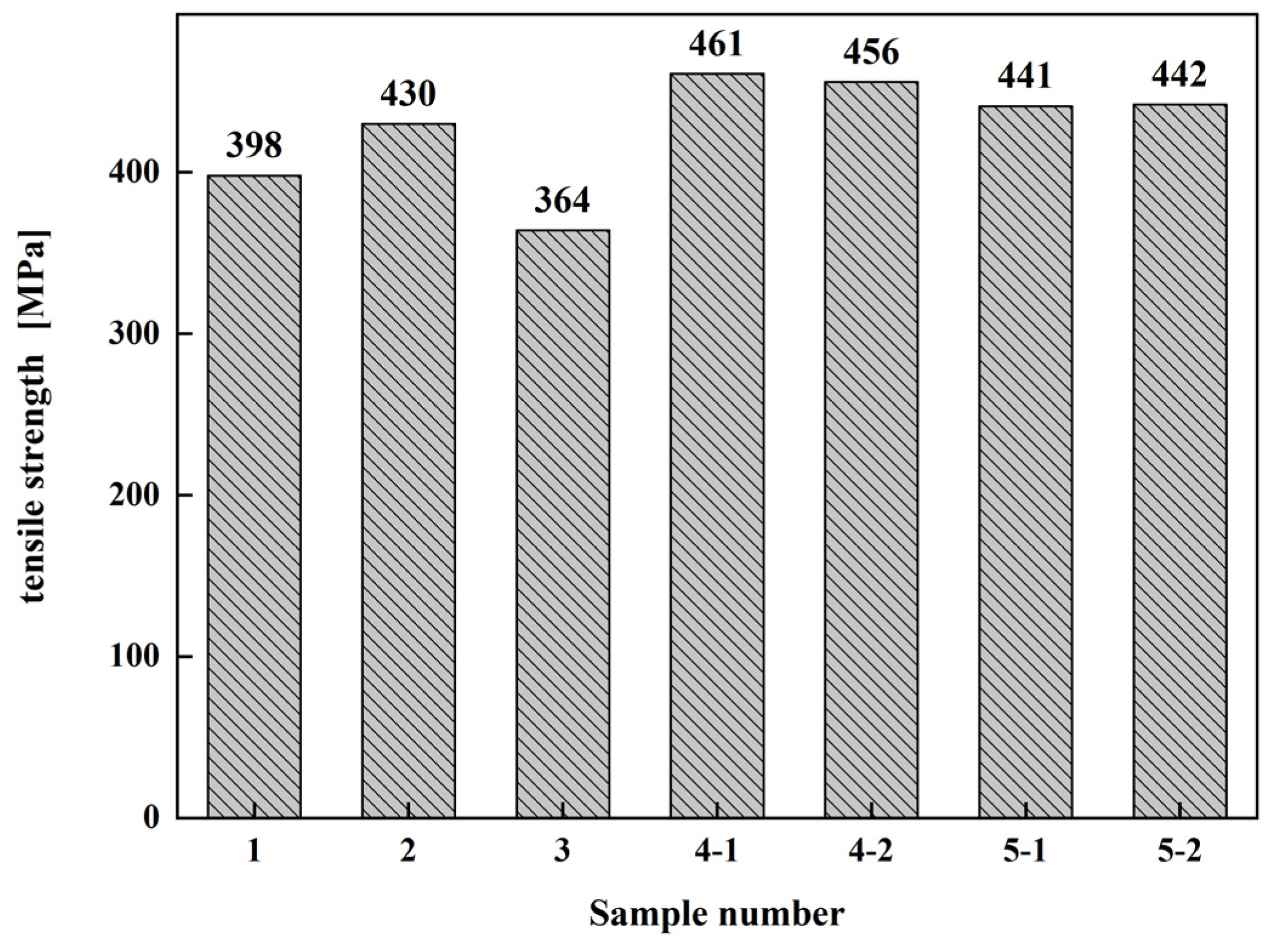
Figure 7. The tensile test results of the average tensile strength are shown in
Figure 8.
It is obvious from
Figure 7b that the fracture position of sample No. 1–3 is in the WS, which indicates that weld metal is weaker than BM. The reason is that the heat input of samples No. 1–3 during the welding process was relatively small, which is not enough to make the welded joints bond well. Among these samples, the tensile strength of the No. 2 sample was 430 MPa, slightly lower than 460 MPa, which is the tensile strength of BM, according to the reference [
24]. This shows that if the laser power remains unchanged, the current intensity has an optimum value matching the laser power on the premise that the thermal input of different groups of experiments is not different. In this case, when the welding current is greater or less than this optimal value, the tensile properties of the welded joint are reduced. The fracture of No. 4 and No. 5 samples occurred in the BM, indicating that the BM was stronger than the weld metal on account of relatively higher input compared to samples No 1–3. This caused successful weld-bonding, which was vindicated by the fact that the fracture took place from the base metal, not from the weld seam. The average tensile strength of the No. 4 and No. 5 specimens was 458.5 MPa and 441.5 MPa, respectively. The tensile strength of the No. 5 sample was slightly less than that of the No. 4 sample. This reveals that a larger heat input within a certain range can enforce a good joint bond and improve the tensile properties of the welded joints. However, when the heat input was too large, the tensile properties of welded joints were reduced. By comprehensive analysis of the microstructure and mechanical properties of all the samples, it was concluded that the performance of the No. 4 specimen was most superior in terms of its load-carrying capability. Although the transverse macrmorphology in
Figure 4d displayed sporadic indications of porosities, it was confirmed by tensile testing that the effects of heat input on the mechanical properties were more pronounced than the cross-sectional area reduction caused by porosities.
The minimum acceptable tensile strength for Q235 steel is 370 MPa [
25]. This research manuscript tried to prove that with proper parameter optimization using Laser-MIG hybrid welding, this process can yield much higher mechanical properties than the minimum desired criteria. This could enable design engineers to design lighter structures by reducing the thickness of load carrying parts while still being able to resist the same deformation as was possible with thicker parts. This can cause manifold advantages such as lesser distortions and residual stresses, reduced costs due to less material requirements and less consumption of filler rods to name a few. In a nutshell, Q235 steel has widespread applications in the field of structural welding. Hence the findings of this manuscript can be used by the industries involved in the Laser-MIG hybrid welding of Q235 steel plates. In future works, the process optimization will be conducted on the T joint using a similar process and filler rod.
4. Conclusions
In this paper, the effects of several important process parameters related to Laser-MIG hybrid arc welding, such as laser power, arc current, the ratio of laser/arc power and heat input, were explored to identify their effects on the quality of welded joints. Accordingly, the following conclusions can be derived from the current results:
(1) During the laser-MIG hybrid welding of Q235 steel, the heat source is concentrated, and the width of the HAZ is narrow due to the synergic effects of the laser and arc. The microstructure of the weld is mainly eutectoid ferrite precipitated along the grain boundary of the original austenite and a small amount of ferrite and pearlite with needle and plate-like morphology between the grains.
(2) The microhardness of welded joints of Q235 steel has a direct relationship with heat input. However, the microhardness is mainly related to the ratio of laser and arc power when the difference in heat input is not obvious.
(3) Within a certain range, the tensile properties of welded joints of Q235 steel increase with the increase of heat input. However, when the heat input is increased to a larger extent, tensile strength begins to decrease. By comparing and analyzing the microstructure and mechanical properties of all samples, it was found that the technological parameters of the No. 4 specimen are the most reasonable, whose tensile strength can obtain 458.5 MPa.
Author Contributions
Conceptualization, S.Z.; data curation, T.Y.; formal analysis, X.Y.; investigation, W.M.; methodology, S.Z.; project administration, X.Z.; resources, Q.G. All authors have read and agreed to the published version of the manuscript.
Funding
This research received no external funding.
Institutional Review Board Statement
Not applicable.
Informed Consent Statement
Not applicable.
Data Availability Statement
Data available on request due to restrictions, e.g., privacy or ethics. The data presented in this study are available on request from the corresponding author. The data are not publicly available due to privacy.
Conflicts of Interest
The authors declare no conflict of interest.
References
- Mi, G.; Xiong, L.; Wang, C.; Hu, X.; Wei, Y. A thermal-metallurgical-mechanical model for laser welding Q235 steel. J. Mater. Processing Technol. 2016, 238, 39–48. [Google Scholar] [CrossRef]
- Cao, X.; Wanjara, P.; Huang, J.; Munro, C.; Nolting, A. Hybrid fiber laser-Arc welding of thick section high strength low alloy steel. Mater. Des. 2011, 32, 3399–3413. [Google Scholar] [CrossRef]
- Xiao, N.; Ruiqiang, L.; Wei, X.; Chenggang, Z.; Hong, L. Effects of stress relief annealing on microstructure and properties of Q235 steel weld joints under different welding currents. Heat Treat. Met. 2012, 37, 65–70. [Google Scholar]
- Turichin, G.; Valdaytseva, E.; Tzibulsky, I.; Lopota, A.; Velichko, O. Simulation and Technology of Hybrid Welding of Thick Steel Parts with High Power Fiber Laser. Phys. Procedia 2011, 12, 646–655. [Google Scholar] [CrossRef]
- Saresh, N.; Pillai, M.G.; Mathew, J. Investigations into the effects of electron beam welding on thick Ti-6Al-4V titanium alloy. J. Mater. Processing Technol. 2007, 192–193, 83–88. [Google Scholar] [CrossRef]
- Zhang, Y.; Li, F.; Liang, Z.; Yiang, Y.; Lin, Q.; Wei, H. Correlation analysis of penetration based on keyhole and plasma plume in laser welding. J. Mater. Processing Technol. 2018, 256, 1–12. [Google Scholar] [CrossRef]
- Wang, L.; Gao, X.; Chen, Z. Status analysis of keyhole bottom in laser-MAG hybrid welding process. Opt. Express 2018, 26, 347–355. [Google Scholar] [CrossRef]
- Kim, J.; Oh, S.; Ki, H. Effect of keyhole geometry and dynamics in zero-gap laser welding of zinc-coated steel sheets. J. Mater. Processing Technol. 2016, 232, 131–141. [Google Scholar] [CrossRef]
- Akman, E.; Demir, A.; Canel, T.; Sınmazçelik, T. Laser welding of Ti6Al4V titanium alloys. J. Mater. Processing Technol. 2009, 209, 3705–3713. [Google Scholar] [CrossRef]
- Takano, K.; Koizumi, N.; Serizawa, H.; Tsubota, S.; Makino, Y. Development of Laser Welding Technology for Fully Austenitic Stainless Steel. Q. J. Jpn. Weld. Soc. 2015, 33, 126–132. [Google Scholar] [CrossRef][Green Version]
- Nikolai, K.; Volker, V.; Gürel, Ç. Prospects of laser beam welding and friction stir welding processes for aluminum airframe structural applications. J. Manuf. Processes 2018, 36, 571–600. [Google Scholar]
- Hong, K.M.; Shin, Y.C. Prospects of laser welding technology in the automotive industry: A review. J. Mater. Processing Technol. 2017, 245, 46–69. [Google Scholar] [CrossRef]
- Panwisawas, C.; Perumal, B.; Ward, R.M.; Turner, N.; Turner, R.P.; Brooks, J.W.; Basoalto, H.C. Keyhole formation and thermal fluid flow-induced porosity during laser fusion welding in titanium alloys: Experimental and modeling. Acta Mater. 2017, 126, 251–263. [Google Scholar] [CrossRef]
- Shi, H.; Zhang, K.; Zheng, J.; Chen, Y. Defects inhibition and process optimization for thick plates laser welding with filler wire. J. Manuf. Processes 2017, 26, 425–432. [Google Scholar] [CrossRef]
- Yan, J.; Gao, M.; Zeng, X. Study on microstructure and mechanical properties of 304 stainless steel joints by TIG, laser and laser -TIG hybrid welding. Opt. Lasers Eng. 2010, 48, 512–517. [Google Scholar] [CrossRef]
- Cui, L.; Chen, B.; Chen, L.; He, D. Dual beam laser keyhole welding of steel/aluminum lapped joints. J. Mater. Process. Technol. 2018, 256, 87–97. [Google Scholar] [CrossRef]
- Kutsuna, M.; Chen, L. Interaction of both plasmas in CO2 laser-MAG hybrid welding of carbon steel. Proc. SPIE Int. Soc. Opt. Eng. 2003, 12, 1675–1683. [Google Scholar]
- Wang, X.; Zhang, S.; Zhou, J. Effect of heat input on microstructure and properties of hybrid fiber laser-arc weld joints of the 800 MPa hot-rolled Nb-Ti-Mo microalloyed steels. Opt. Lasers Eng. 2017, 91, 86–96. [Google Scholar] [CrossRef]
- Roepke, C.; Liu, S. Hybrid Laser Arc Welding of HY-80 Steel. Suppl. Weld. J. 2009, 88, 159–167. [Google Scholar]
- Zhang, C.; Gao, M.; Jiang, M.; Zeng, X. Effect of Weld Characteristic on Mechanical Strength of Laser-Arc Hybrid-Welded Al-Mg-Si-Mn Aluminum Alloy. Metall. Mater. Trans. A 2016, 47, 5438–5449. [Google Scholar] [CrossRef]
- Zhan, X.; Zhao, Y.; Liu, Z.; Gao, Q.; Bu, H. Microstructure and porosity characteristics of 5A06 aluminum alloy joints using laser-MIG hybrid welding. J. Manuf. Processes 2018, 35, 437–445. [Google Scholar] [CrossRef]
- Zhan, X.; Li, Y.; Ou, W.; Yu, F.; Chen, J.; Wei, Y. Comparison between hybrid laser-MIG welding and MIG welding for the invar36 alloy. Opt. Laser Technol. 2016, 85, 75–84. [Google Scholar] [CrossRef]
- Mahmoud, M.; Majid, G.; Ali, K. Process and outcome comparison between laser, tungsten inert gas (TIG) and laser-TIG hybrid welding. Lasers Eng. 2018, 39, 3–6. [Google Scholar]
- Chen, H.; Guo, N.; Zhang, X. Effect of water flow on the microstructure, mechanical performance, and cracking susceptibility of underwater wet welded Q235 and E40 steel. J. Mater. Process. Technol. 2020, 277, 116435. [Google Scholar] [CrossRef]
- Yang, M.; Ma, H.; Shen, Z.; Huang, Z.; Tian, Q.; Tian, J. Dissimilar material welding of tantalum foil and Q235 steel plate using improved explosive welding technique. Mater. Des. 2020, 186, 108348. [Google Scholar] [CrossRef]
| Publisher’s Note: MDPI stays neutral with regard to jurisdictional claims in published maps and institutional affiliations. |
© 2021 by the authors. Licensee MDPI, Basel, Switzerland. This article is an open access article distributed under the terms and conditions of the Creative Commons Attribution (CC BY) license (https://creativecommons.org/licenses/by/4.0/).


