Article

Bone Damage during Dental Implant Insertion: A Pilot Study Combining Strain Gauge and Histologic Analysis

Department of Prosthodontics, Saarland University, 66421 Homburg, Saar, Germany
*
Author to whom correspondence should be addressed.
Appl. Sci. 2022, 12(1), 291; https://doi.org/10.3390/app12010291
Submission received: 29 November 2021 / Revised: 20 December 2021 / Accepted: 27 December 2021 / Published: 29 December 2021
(This article belongs to the Section Applied Dentistry and Oral Sciences)

Abstract

:
Besides alveolar bone quality, the drilling protocol applied in conjunction with the design of an implant are the major determinants of primary implant stability. Surgical trauma and bone compression resulting from implant insertion may constitute one cause for marginal bone resorption. Inserting two current bone-level implant designs (Astra; Straumann; n = 5) in bovine ribs, primary stability, strain development on the buccal bone plate and histologic signs of bone damage were recorded. Besides comparing the implant designs (Welch t-tests), all measurement parameters were checked for potential correlations (Pearson product moment correlation coefficients) with the level of significance set at α = 0.05. Considerable numbers of crack formation and plastic deformation of bone were observed after implant insertion. Straumann implants showed slightly greater values for insertion torque (p = 0.772), strain development (p = 0.893) and implant stability (p = 0.642). Significantly greater bone to implant contact (cortical p = 0.014; trabecular p = 0.016) was observed in Straumann implants, while Astra implants caused a significantly greater number of microcracks in cortical bone (p = 0.020). In Straumann implants, insertion torque correlated with bone to implant contact in the cortical area (p = 0.029) and the number of macrocracks in trabecular bone correlated with bone to implant contact (p = 0.029). In Astra implants, insertion torque and bone to implant contact in the trabecular area correlated (p = 0.007) as well as the number of macrocracks in trabecular bone and implant stability (p = 0.016). Additionally, in the area of cortical bone, the number of macrocracks correlated with bone to implant contact (p = 0.019). Implant placement results in bone damage of varying magnitude, which is governed by the drill protocol, implant macrodesign and bone quality.

1. Introduction

Alveolar bone consists of cortical and trabecular compartments in varying percent composition resulting in different bone qualities [1,2]. When dental implants are placed, primary stability reducing micromotion at the implant–bone interface in order to ensure osseointegration, has to be achieved. In this context, a clinical study showed that implants with low initial stability bear a higher risk of failure [3].
With shortened treatment protocols, implant manufacturers strive for maximizing primary stability by defining drill protocols depending on the hard to evaluate bone quality, and by designing implants often causing compression especially in the cortical layer of bone [2,4,5,6]. The exact implications of the factors mentioned are not yet well known with partially contradictive results presented in literature. In an animal study comparing different drill protocols, a correlation between insertion torque and radiographic bone loss after 6 weeks of healing was found with implants achieving greater torque showing more marginal bone loss [7]. On the other hand, a clinical study showed that microstructural bone characteristics had no effect on changes in marginal bone level and implant stability [1]. A further clinical study found that implant survival was associated with intermediate bone types; the authors concluded that both, very sparse or very dense bone are critical [8].
With marginal bone resorption causing problems with both, esthetics and maintenance, several potential factors, including vertical positioning and implant abutment connection [9,10], governing bone response to dental implant placement have been investigated. Besides establishing biologic width, initial marginal bone loss after implant placement has been described as the result of an adaptive bone response to surgical trauma and implant loading [11]. Based on a recent clinical study including 22 implants, the extent of initial marginal bone loss between implant insertion and prosthetic restoration averages 0.41 mm (SD = 0.45 mm) [12].
As a potential solution to mechanically overloading alveolar bone during implant insertion, implants with a triangular cross-section have been introduced. Following the creation of a round osteotomy, the insertion of a triangular implant with a flat surface oriented buccally would relieve the buccal bone plate. However, two clinical studies did not identify major differences with circular cross-section neck implants [13] apart from somewhat reduced crestal bone loss [14].
It was the goal of this ex vivo experiment to quantify primary implant stability and strain development on the surface of the buccal bone plate during insertion of two current bone-level implant types and to examine potential correlations with histologically assessed bone damage.

2. Materials and Methods

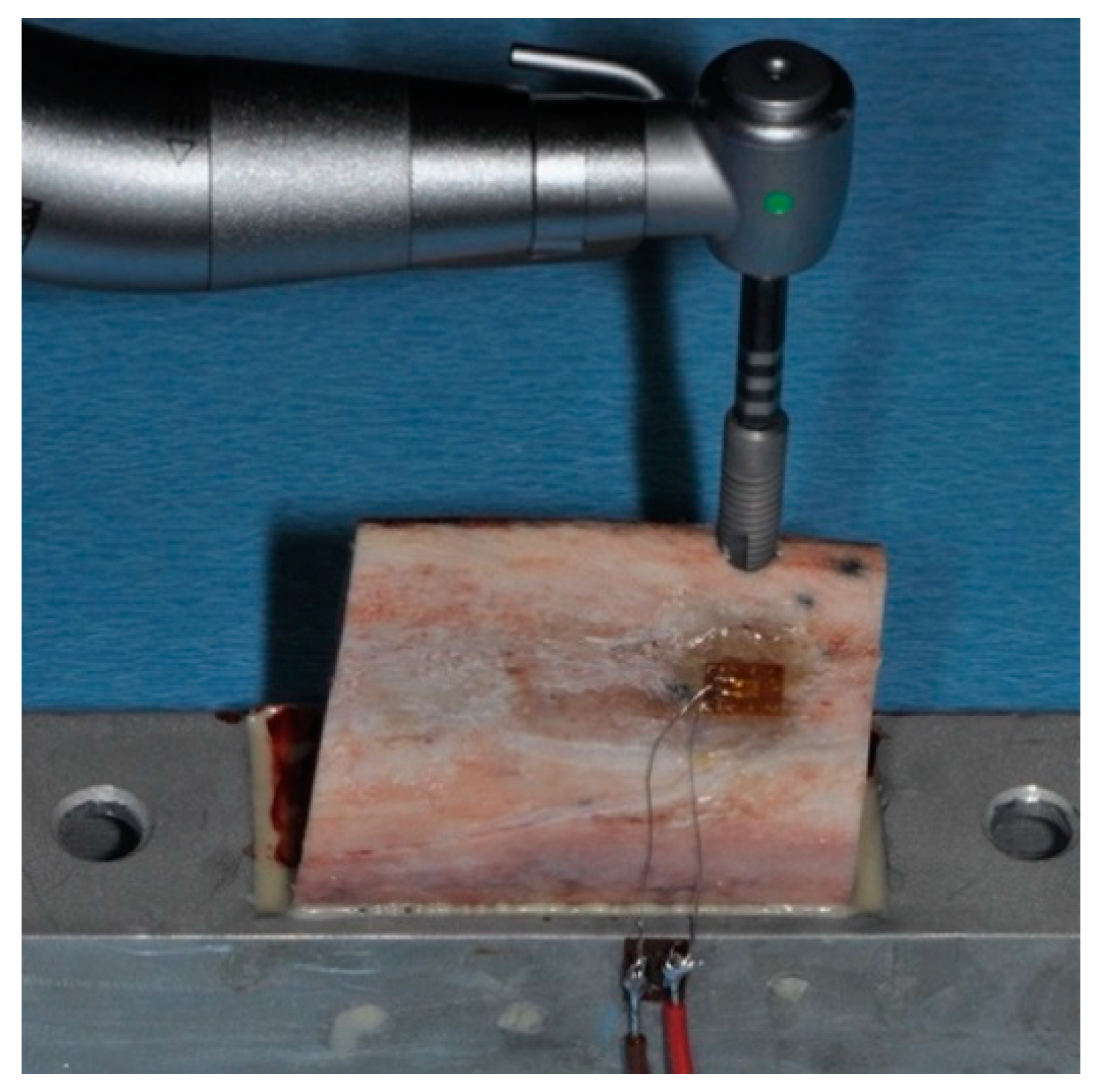
2.1. Biomechanical Measurements

Bovine ribs were freshly obtained from the local slaughterhouse, cut into pieces with a length of 30 mm using a diamond band saw (EXAKT 300, EXAKT Advanced Technologies GmbH, Norderstedt, Germany) and the periosteum was removed completely. The specimens were then embedded in metal holders using polyurethane resin (Biresin G27, Sika Deutschland GmbH, Bad Urach, Germany), which allowed for the stable fixation on a metal plate for handling purposes. All biomechanical study parts were completed in one day in order not to require freezing and thawing.
Following the implant manufacturers’ protocols for medium type bone (Table 1), a surgical motor (iChiropro, BienAir, Biel, Switzerland) was used for creating osteotomies with a distance of approximately 2 mm to the cortical plate, simulating the buccal bone surface (Figure 1). In order to ensure perpendicular osteotomies, a metal guide sleeve could be positioned on the top surface of the bone samples. Unidirectional strain gauges (LY11-0.6/120, 120 Ω reference resistance, Hottinger Baldwin Messtechnik GmbH, Darmstadt, Germany) were attached to the bone surface with the sensing element oriented in the mesio-distal direction using a dentin bonding agent [15]. Solder tags (LS 7; Hottinger Baldwin Messtechnik GmbH) were attached to the metal holders using cyanoacrylate followed by usual wiring. A measurement amplifier (Quantum X, Hottinger Baldwin Messtechnik GmbH) and analyzing software (jBEAM, AMS GmbH, Chemnitz, Germany) were used for recording strain development during the insertion of two groups of current bone-level implants (n = 5; Table 1) at a maximum velocity of 25 rpm. Following implant insertion, resonance frequency analysis was performed, both in the mesio-distal and bucco-lingual direction using implant specific smart peg abutments and an Osstell ISQ device (implant stability quotient; Osstell AB, Gothenburg, Sweden).

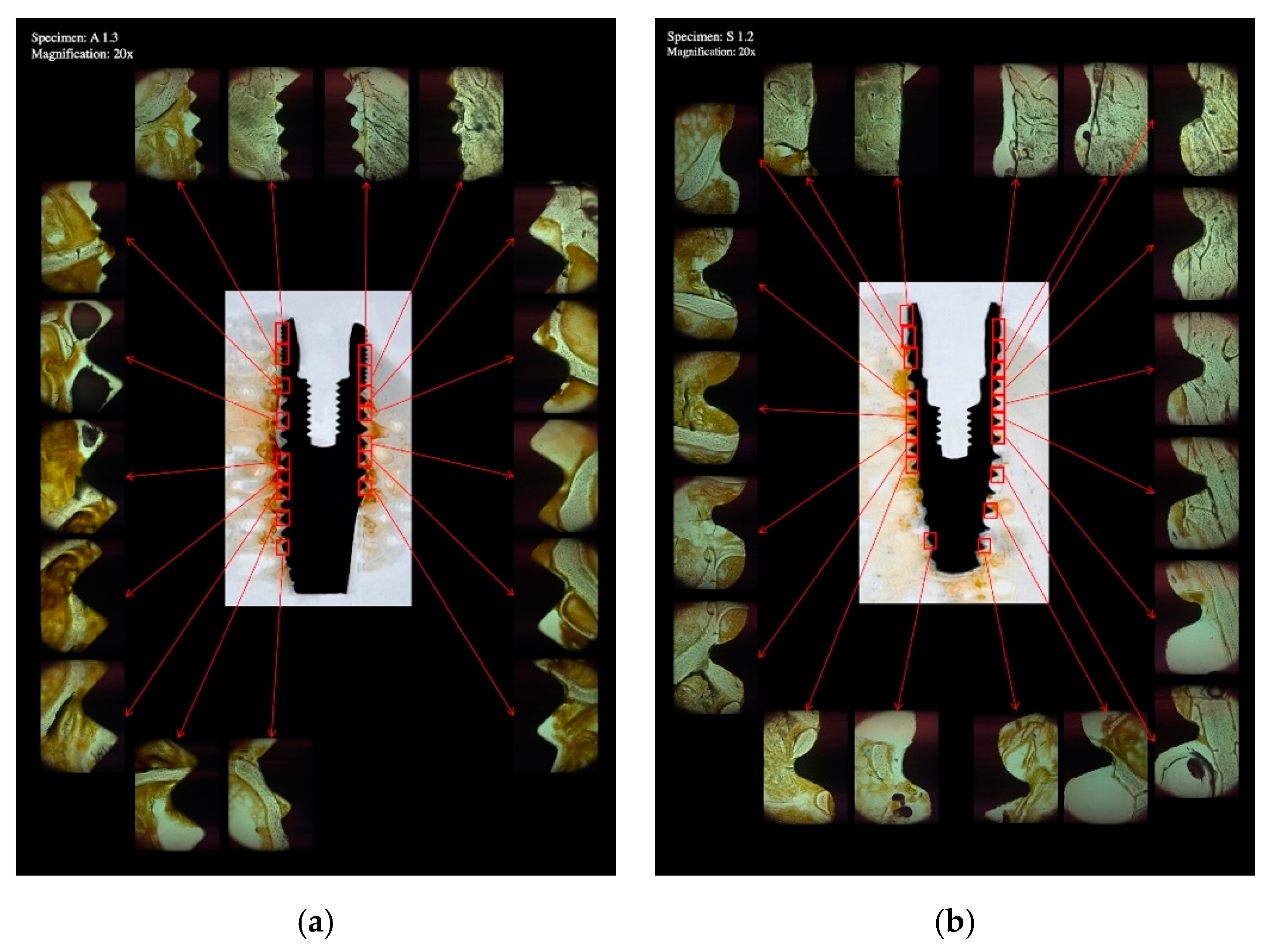
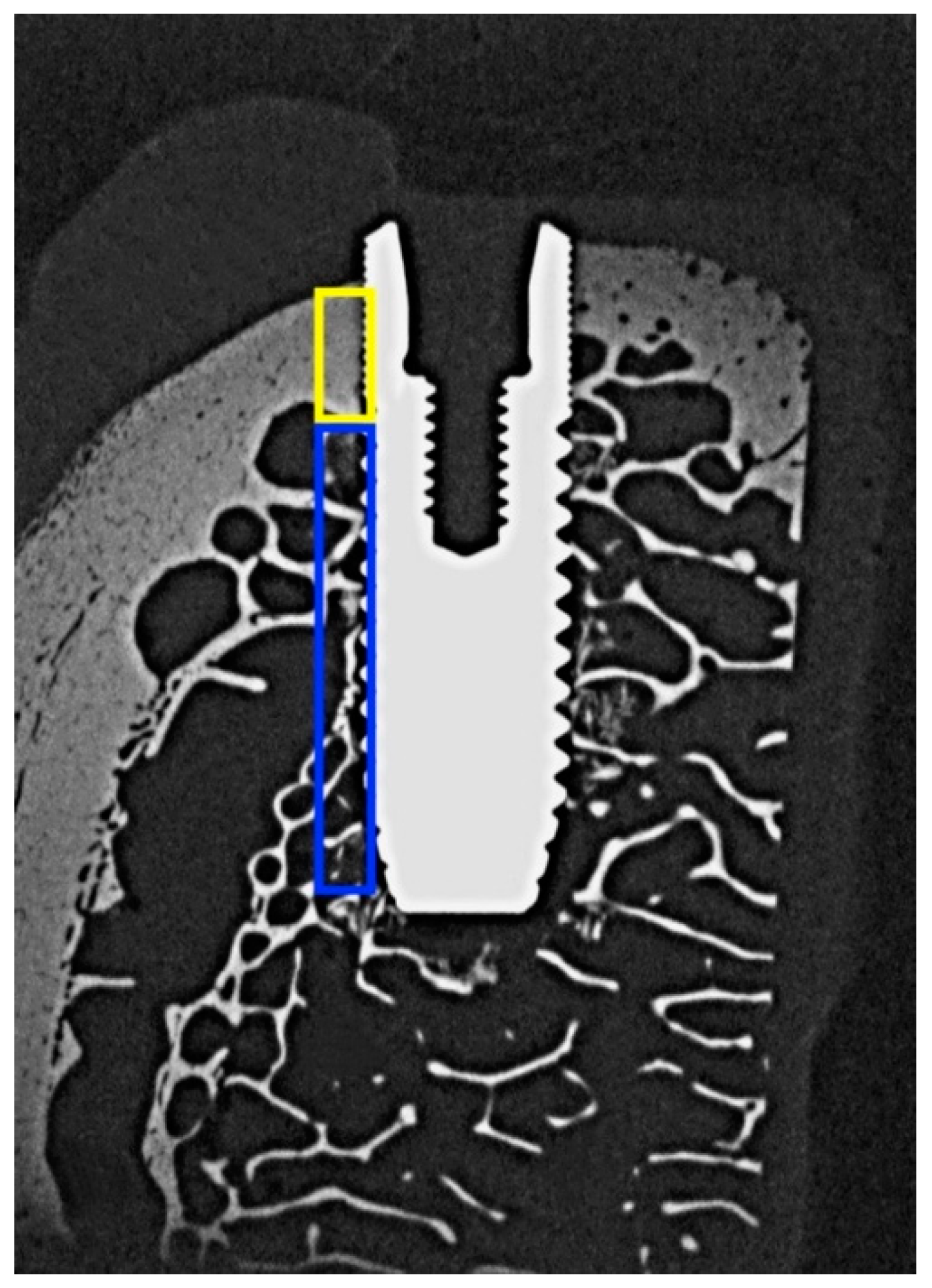
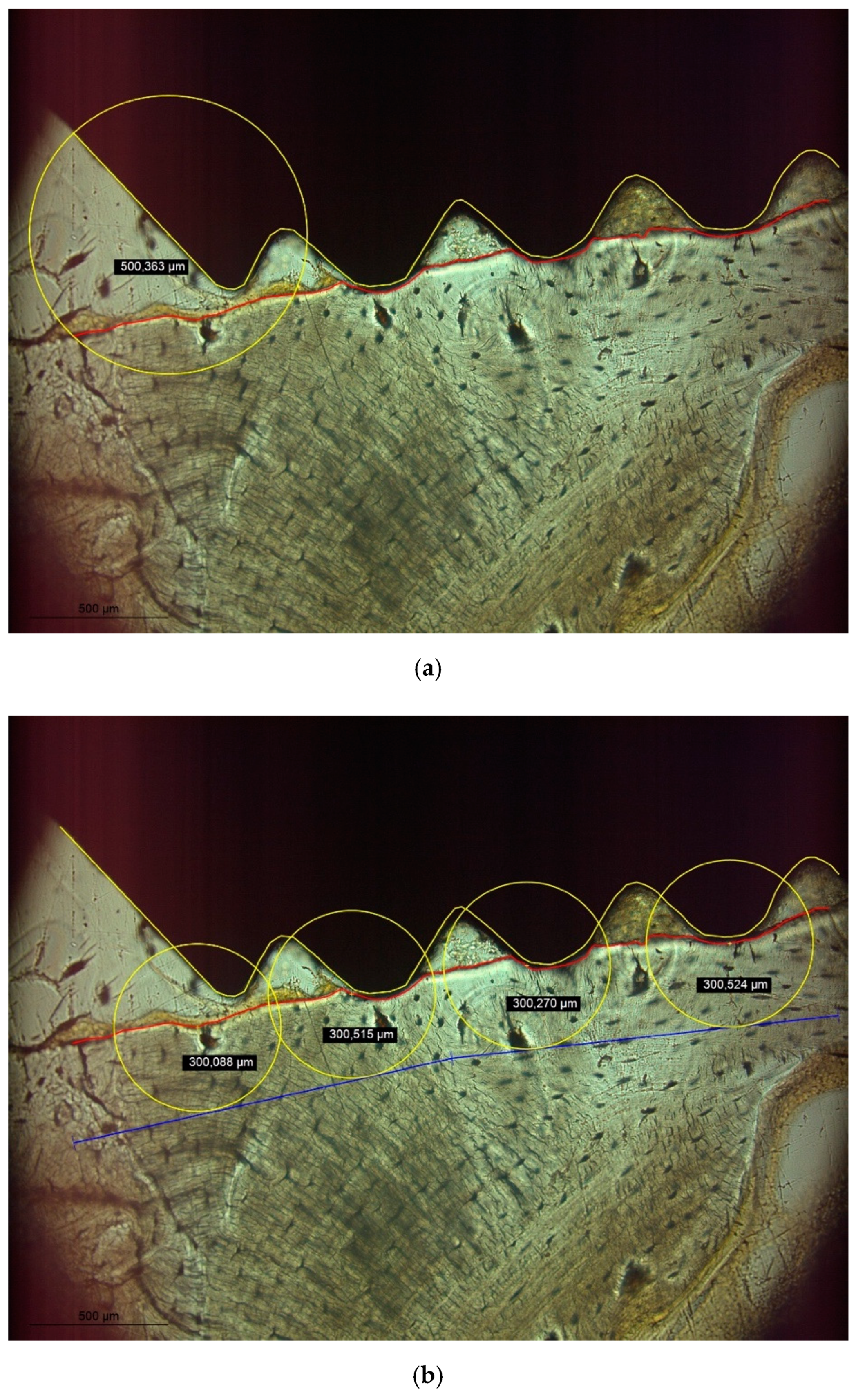
2.2. Histologic Analysis

With the implants in place, the specimens were removed from the metal holders by cutting at a distance of 10 mm relative to the surface of the implants using the diamond band saw described above. Subsequently, the specimens were dehydrated in alcohol solutions of increasing concentrations, clarified in xylene and embedded in polymethylmethacrylate (Technovit 9100, Heraeus Kulzer, Hanau, Germany). One sagittal section (Figure 2) parallel to the long axis of the implant and corresponding to the center of the strain gauge was obtained per specimen by a cutting and grinding technique [16]. With the sections reduced to a thickness of 120 µm, microradiographs (Faxitron X-ray, Lincolnshire, IL, USA; 14 kV, 0.3 mA, 2.5 min; Insight Dental Film, Carestream Health Inc., Rochester, NY, USA) were obtained for determining bone mineral density (BMD) in the surrounding of the implants (Figure 3). Following further reduction of the sections to a thickness of 30 µm, bone to implant contact (BIC) and bone damage were quantified histomorphometrically using a microscope (LEICA DM4B, LEICA Mikrosysteme Vertrieb GmbH, Wetzlar, Germany) equipped with a color image analyzing system (LEICA Application Suite, LEICA Phase Expert, LEICA Mikrosysteme Vertrieb GmbH). All measurements were made on images gathered at 20× magnification. Following the outlining of the implant surface (Figure 4a, yellow line) and the internal bony wall of the drill holes (Figure 4a, red line), BIC was defined as bone appearing within a radius of 500 µm surrounding a specific point on the implant surface. The region of interest for evaluating bone damage was defined by circles with a radius of 300 µm surrounding the bony walls at points best representing the outer geometry of the implants (Figure 4b, blue line). Bone damage, as indicated by crack formation or deformation of bone structure, was quantified with cracks exceeding 100 µm being classified as macrocracks, while cracks with a length shorter than 100 µm were classified as microcracks.

2.3. Statistical Analysis

Statistical analysis was based on maximum insertion torque, maximum strain development and mean values of primary implant stability and all histologic parameters, which were separately determined for the cortical and trabecular parts of bone. Following descriptive statistics, Shapiro–Wilk tests on normality of distribution of measurement values were performed, followed by Welch t-tests for comparing Astra vs. Straumann implants (n = 5). Pearson product moment correlation coefficients were calculated for evaluating potential correlations among measurement parameters. All calculations were carried out using the R software package (R, The R Foundation for Statistical Computing, Vienna, Austria; www.R-project.org; accessed 18 November 2021) with the level of significance set at α = 0.05.

3. Results

The mean values and standard deviations for all measurement parameters are given in Table 2. In five instances, the Shapiro–Wilk tests indicated a non-normal distribution of measurement values (Table 2). Only in three comparisons between implant types, a significant difference could be observed (Table 2).
Slightly higher insertion torque (p = 0.772), strain development (p = 0.893) and implant stability (p = 0.642) were seen in Straumann implants but did not significantly differ from Astra implants. As expected, bone mineral density in the cortical (p = 0.466) and trabecular (p = 0.360) area did not differ between groups.
Significantly greater bone to implant contact was observed in Straumann implants, both in cortical (p = 0.014) and trabecular (p = 0.016) areas. However, Astra implants caused a significantly greater number of microcracks in cortical bone (p = 0.020). No further significant differences with respect to bone damage were observed between the groups.
In general, only a few and weak correlations were seen between the different parameters recorded (Table 3). In Straumann implants, insertion torque correlated with bone to implant contact in the cortical area (p = 0.029), while in trabecular bone, the number of macrocracks correlated with bone to implant contact (p = 0.029). In Astra implants, a correlation between insertion torque and bone to implant contact in the trabecular area was found (p = 0.007) as well as a correlation between the number of macrocracks in trabecular bone and implant stability (p = 0.016). Additionally, in the area of cortical bone, the number of macrocracks correlated with bone to implant contact (p = 0.019).

4. Discussion

Considerable numbers of crack formation and plastic deformation of bone have been shown as a consequence of implant site preparation and implant insertion. While exact thresholds for bone damage are unknown, bone resorption as a consequence of mechanical trauma may originate from such regions. Consequently, marginal bone loss of up to 1 mm in the first year after implant placement is still widely accepted as success criterion [11,12].
Based on biomechanical parameters, Straumann implants showed a trend towards greater primary stability as compared to Astra implants. In agreement with this finding, greater values of bone to implant contact, both in cortical and trabecular areas of bone, were seen in Straumann implants. While the insertion torque of Straumann implants correlated with bone to implant contact in the cortical area, for Astra implants, a correlation for insertion torque with bone to implant contact in trabecular bone was observed. Macrocracks in trabecular bone correlated with bone to implant contact in Straumann implants but with implant stability in Astra implants. Furthermore, Straumann implants caused less microcracks in cortical bone as compared to Astra implants, for which bone to implant contact in cortical bone correlated with the number of macrocracks detected. Given that bone mineral density did not significantly differ between Straumann and Astra specimens, it appears that the implants tested here derive primary stability by engaging different areas of bone [2,5]. Differences in thread design in the cervical area in combination with the drill protocols used here obviously result in less cortical bone damage in Straumann implants as compared to Astra implants.
Only a few and weak correlations among measurement parameters were observed in this study, which has previously also been experienced by other authors [5]. This may be due to the fact that clinical measurements, such as insertion torque and implant stability are rather global in nature, while histologic analysis focusses on very specific parts of the implant bone interface.
The study at hand used two dental implant systems differing in length, diameter, thread pitch and drill protocol. Instead of standardizing, e.g., implant site preparation with respect to undersizing the osteotomy [6,7], the manufacturers’ guidelines were applied in order to best reflect clinical practice. While not reported here, this also resulted in different vertical start positions for implant insertion and varying amounts of time required for the insertion process despite a standardized insertion velocity.
As with every in vitro investigation, several limiting factors have to be considered when interpreting the results. For analyzing bone damage, no staining was carried out here based on preliminary tests with toluidine blue staining [17] and fluorescent dye [18], as native bone resulted in the best visual appearance of cracks and deformed bone areas. However, originally basic fuchsin staining has been described as being necessary for analyzing bone damage [19]. Bone to implant contact is normally defined as intimate contact between dental implant and bone during or after healing. In this study, BIC was defined as an area in which surgical trauma caused by implant site preparation or implant insertion may have caused bone damage. Based on an initial screening of the specimens, a radius of 500 µm surrounding a specific point of an implant was chosen while a radius of 300 µm centered at the bony wall of an implant socket was chosen as area of interest for determining bone damage. Wide variation was seen in the measurements performed, which at least partially has to be attributed to the bone material used being characterized by varying thickness of cortical bone. With the insertion characteristics of dental implants also depending on surface characteristics, each implant was used only once. Reducing the effect of varying bone morphology would have required a much greater sample size, which seemed not to be feasible for a pilot study. For comparative biomechanical studies employing different implant systems, a greater level of standardization should be implemented, e.g., by using foam materials as bone surrogate material [4].
Due to the limited sample size chosen in this pilot investigation, normal distribution of measurement values may not be guaranteed even if the Shapiro–Wilk test indicated p > 0.05. Both Welch t-tests for pairwise comparisons and Pearson product moment correlation coefficients are not very sensitive with respect to a violation of normal distribution of measurement values. Under this assumption, non-parametric tests seemed not to be required for statistical analysis. Furthermore, the statistical power achieved with the given sample size was low (<0.8), with the exception of the parameters BICt and microC. This does not affect differences which were found to be significant but may obscure non-significant differences as errors of second order.

5. Conclusions

Implant placement employing currently available systems and drill protocols inevitably results in bone damage of varying magnitude. The amount of undersizing an osteotomy relative to the implant diameter seems to be critical and greater primary stability can be associated to greater levels of damage. The macrodesign of an implant determines which areas of bone are being engaged and consequently, novel implant designs should preferably derive stability from trabecular bone while avoiding bone damage in cortical areas. Further benefit could be derived from drill protocols requiring less removal of alveolar bone.

Author Contributions

Conceptualization: T.G.-K.; Methodology: T.G.-K. and V.K.; Formal analysis: M.K.; Data curation: T.G.-K. and V.K.; Writing—original draft preparation: V.K. and M.K.; Writing—review and editing: T.G.-K. and V.K. All authors have read and agreed to the published version of the manuscript.

Funding

This research received no external funding.

Institutional Review Board Statement

Not applicable.

Informed Consent Statement

Not applicable.

Acknowledgments

The experiments were carried out by Virgilia Klär in partial fulfillment of the requirements for the degree Dr. med. dent. at Saarland University, Homburg, Germany. The authors wish to thank Friedrich Graef, Department of Mathematics, University of Erlangen-Nuremberg for statistical data analysis.

Conflicts of Interest

The authors declare no conflict of interest.

References

  1. Dias, D.R.; Leles, C.R.; Lindh, C.; Ribeiro-Rotta, R.F. Marginal bone level changes and implant stability after loading are not influenced by baseline microstructural bone characteristics: 1-year follow-up. Clin. Oral Implant. Res. 2016, 27, 1212–1220. [Google Scholar] [CrossRef] [PubMed]
  2. Gehrke, S.A.; Pérez-Díaz, L.; Mazón, P.; De Aza, P.N. Biomechanical Effects of a New Macrogeometry Design of Dental Implants: An In Vitro Experimental Analysis. J. Funct. Biomater. 2019, 10, 47. [Google Scholar] [CrossRef] [PubMed] [Green Version]
  3. Chen, M.H.; Lyons, K.; Tawse-Smith, A.; Ma, S. Resonance Frequency Analysis in Assessing Implant Stability: A Retrospective Analysis. Int. J. Prosthodont. 2019, 32, 317–326. [Google Scholar] [CrossRef] [PubMed]
  4. Pérez-Pevida, E.; Cherro, R.; Camps-Font, O.; Piqué, N. Effects of Drilling Protocol and Bone Density on the Stability of Implants According to Different Macrogeometries of the Implant Used: Results of an In Vitro Study. Int. J. Oral Maxillofac. Implant. 2020, 35, 955–964. [Google Scholar] [CrossRef] [PubMed]
  5. Dard, M.; Kuehne, S.; Obrecht, M.; Grandin, M.; Helfenstein, J.; Pippenger, B.E. Integrative Performance Analysis of a Novel Bone Level Tapered Implant. Adv. Dent. Res. 2016, 28, 28–33. [Google Scholar] [CrossRef] [PubMed] [Green Version]
  6. Gazelakis, E.; Judge, R.B.; Palamara, J.E.A. The biomechanical profile of an osseo-integrated rectangular block implant: A pilot in vivo experimental study. Clin. Oral Implant. Res. 2021, 32, 1274–1287. [Google Scholar] [CrossRef] [PubMed]
  7. Abrahamsson, I.; Carcuac, O.; Berglundh, T. Influence of implant geometry and osteotomy design on early bone healing: A pre-clinical in vivo study. Clin. Oral Implant. Res. 2021, 32, 1190–1199. [Google Scholar] [CrossRef] [PubMed]
  8. Nicolielo, L.F.P.; Van Dessel, J.; Jacobs, R.; Quirino Silveira Soares, M.; Collaert, B. Relationship between trabecular bone architecture and early dental implant failure in the posterior region of the mandible. Clin. Oral Implant. Res. 2020, 31, 153–161. [Google Scholar] [CrossRef] [PubMed]
  9. Agustín-Panadero, R.; Martínez-Martínez, N.; Fernandez-Estevan, L.; Faus-López, J.; Solá-Ruíz, M.F. Influence of Transmucosal Area Morphology on Peri-Implant Bone Loss in Tissue-Level Implants. Int. J. Oral Maxillofac. Implant. 2019, 34, 947–952. [Google Scholar] [CrossRef] [PubMed]
  10. Palombo, D.; Rahmati, M.; Vignoletti, F.; Sanz-Esporrin, J.; Haugen, H.J.; Sanz, M. Hard and soft tissue healing around implants with a modified implant neck configuration: An experimental in vivo preclinical investigation. Clin. Oral Implant. Res. 2021, 32, 1127–1141. [Google Scholar] [CrossRef] [PubMed]
  11. Albrektsson, T.; Chrcanovic, B.; Östman, P.O.; Sennerby, L. Initial and long-term crestal bone responses to modern dental implants. Periodontol. 2000 2017, 73, 41–50. [Google Scholar] [CrossRef] [PubMed]
  12. Friberg, B.; Ahmadzai, M. A prospective study on single tooth reconstructions using parallel walled implants with internal connection (NobelParallel CC) and abutments with angulated screw channels (ASC). Clin. Implant. Dent. Relat. Res. 2019, 21, 226–231. [Google Scholar] [CrossRef] [PubMed]
  13. Li Manni, L.; Lecloux, G.; Rompen, E.; Aouini, W.; Shapira, L.; Lambert, F. Clinical and radiographic assessment of circular versus triangular cross-section neck Implants in the posterior maxilla: A 1-year randomized controlled trial. Clin. Oral Implant. Res. 2020, 31, 814–824. [Google Scholar] [CrossRef] [PubMed]
  14. Tokuc, B.; Kan, B. The effect of triangular cross-section neck design on crestal bone stability in the anterior mandible: A randomized, controlled, split-mouth clinical trial. Clin. Oral Implant. Res. 2021, 32, 1241–1250. [Google Scholar] [CrossRef] [PubMed]
  15. Grobecker-Karl, T.; Orujov, K.; Klär, V.; Karl, M. Use of a dentin bonding agent for the fixation of strain gauges on bone. J. Mech. Behav. Biomed. Mater. 2021, 119, 104545. [Google Scholar] [CrossRef] [PubMed]
  16. Donath, K.; Breuner, G. A method for the study of undecalcified bones and teeth with attached soft tissues. The Säge-Schliff (sawing and grinding) technique. J. Oral Pathol. 1982, 11, 318–326. [Google Scholar] [CrossRef] [PubMed]
  17. Karl, M.; Palarie, V.; Nacu, V.; Grobecker-Karl, T. A Pilot Animal Study Aimed at Assessing the Mechanical Quality of Regenerated Alveolar Bone. Int. J. Oral Maxillofac. Implant. 2020, 35, 313–319. [Google Scholar] [CrossRef] [PubMed]
  18. Grobecker-Karl, T.; Christian, M.; Karl, M. Effect of endodontic access cavity preparation on monolithic and ceramic veneered zirconia restorations. Quintessence Int. 2016, 47, 725–729. [Google Scholar] [PubMed]
  19. Burr, D.B.; Hooser, M. Alterations to the en bloc basic fuchsin staining protocol for the demonstration of microdamage produced in vivo. Bone 1995, 17, 431–433. [Google Scholar] [CrossRef]
Figure 1. Insertion of an OsseoSpeed implant in bovine rib bone, which has been positioned in a metal holder and equipped with a strain gauge on the buccal surface. The sensing element of the strain gauge is positioned in the horizontal direction.
Applsci 12 00291 g001
Figure 2. Overview of a histologic section showing an OsseoSpeed (a) and a Straumann BLT (b) implant placed in bovine rib bone. The implant bone interface was analyzed in varying numbers of images at 20× magnification.
Applsci 12 00291 g002
Figure 3. Microradiograph of an OsseoSpeed implant placed in bovine rib bone and sectioned in the bucco-lingual direction. The areas used for determining bone mineral density (BMD) in the cortical and trabecular parts are outlined in yellow and blue color respectively.
Applsci 12 00291 g003
Figure 4. (a) BIC was defined as bone being present within a radius of 500 µm surrounding a specific point of the implant surface (yellow line). (b) The bony walls of the implant socket were identified (red line) and a radius of 300 µm surrounding a specific point of the bony socket was defined as region of interest for determining bone damage.
Applsci 12 00291 g004
Table 1. Implant types and drill protocols.
Group NameStraumannAstra
ImplantStraumann Bone Level
Tapered 4.1 × 12 mm
(Institut Straumann AG, Basel, Switzerland)
OsseoSpeed TX 4.0 S × 13 mm
(Astra Tech Implant System, Dentsply Implants Manufacturing GmbH, Mannheim, Germany)
Drill sequenceNeedle drillRound bur
2.2 mm pilot drillTwist drill 2.0
2.8 mm BLT drillTwist drill 3.2
3.5 mm BLT drillTwist drill 3.7
Table 2. Descriptive statistics and pairwise comparisons of the two implant types investigated. Significant differences between groups (p < 0.05) are written in bold.
ASTRAStraumannWelch t-Tests (p-Value)
MeanSDMeanSD
Torque29.7626.89334.0817.4280.772
Strain383.38299.860410.84284.7540.893
ISQ* 79.2011.33981.802.8420.642
BMDc0.8940.0250.8720.0580.466
BMDt0.4860.0990.4340.0650.360
BICc0.7560.0590.8680.0540.014
BICt0.4280.0640.6000.1010.016
microC** 92.20426.24149.7327.3180.020
microT*** 44.48418.810**** 45.03423.7330.969
macroC10.8621.44311.0202.0730.893
macroT5.4940.9766.2863.0450.600
defC0.5920.5040.3260.1950.320
defT0.3680.161***** 0.4180.2260.699
p-values of Shapiro–Wilk tests indicating a non-normal distribution of measurement values: * 0.014; ** 0.019; *** 0.050; **** 0.028; ***** 0.004. Abbreviations and units: Torque [Ncm]: implant insertion torque; Strain [µm/m]: strain development on buccal bone; ISQ [no physical unit]: implant stability quotient; BMDc [%]: bone mineral density in the cortical area; BMDt [%]: bone mineral density in the trabecular area; BICc [%]: bone to implant contact in the cortical area; BICt [%]: bone to implant contact in the trabecular area; microC [quantity]: total number of microcracks detected in cortical bone; microT [quantity]: total number of microcracks detected in trabecular bone; macroC [quantity]: number of macrocracks detected in cortical bone; macroT [quantity]: number of macrocracks detected in trabecular bone; defC [quantity]: total number of deformed bone areas detected in cortical bone; defT [quantity]: total number of deformed bone areas in trabecular bone.
Table 3. (a) Pearson product moment correlation coefficients for measurement parameters recorded in ASTRA implants. (b) Pearson product moment correlation coefficients for measurement parameters recorded in Straumann implants.
(a)
Correlation Coefficients
TorqueStrainISQBMDcBMDtBICcBICtmicroCmicroTmacroCmacroTdefCdefT
Torque −0.2390.6650.6350.867−0.4310.969−0.259−0.212−0.5020.7260.1790.549
Strain0.761 0.5110.4430.3000.8590.0130.8610.7450.870−0.700−0.566−0.902
ISQ0.2210.490 0.6640.7620.0030.6650.0930.3930.1070.9430.3130.006
BMDc0.2500.5570.222 0.6520.3850.782−0.0070.0030.2200.5030.339−0.115
BMDt0.0570.7000.1340.233 −0.1280.8960.2510.270−0.1050.685−0.1730.119
BICc0.4690.1410.9960.5220.838 −0.2070.5590.4590.937−0.305−0.095−0.911
BICt0.0070.9870.2200.1180.0390.738 −0.140−0.152−0.3200.6500.1350.369
microC0.6740.1400.8820.9920.6840.3270.823 0.8850.721−0.171−0.773−0.809
microT0.7320.2550.5130.9970.6600.4370.8070.046 0.7180.180−0.485−0.743
macroC0.3290.1300.8640.7220.8670.0190.5990.1690.172 −0.194−0.200−0.983
macroT0.1650.2300.0160.3880.2020.6180.2360.7830.7720.755 0.4390.310
defC0.7740.4340.6090.5770.7800.8790.8280.1250.4080.7460.460 0.370
defT0.3380.0980.9930.8540.8490.0320.5410.0980.1500.0030.6120.540
p-values
(b)
Correlation Coefficients
TorqueStrainISQBMDcBMDtBICcBICtmicroCmicroTmacroCmacroTdefCdefT
Torque −0.1380.0400.1200.237−0.9160.458−0.3080.4830.4980.681−0.036−0.764
Strain0.825 0.0230.6240.5780.351−0.560−0.235−0.164−0.048−0.2520.673−0.480
ISQ0.9490.970 0.3620.3350.301−0.6000.618−0.8190.608−0.5970.699−0.115
BMDc0.8480.2610.550 0.9920.156−0.7540.434−0.1270.701−0.4720.852−0.327
BMDt0.7010.3070.5820.001 0.031−0.6720.394−0.0390.748−0.3720.810−0.394
BICc0.0290.5620.6230.8030.960 −0.7370.435−0.739−0.251−0.8680.4150.545
BICt0.4380.3260.2850.1410.2140.155 −0.6560.676−0.4030.915−0.884−0.118
microC0.6150.7030.2660.4660.5120.4640.230 −0.4990.629−0.7910.4400.520
microT0.4100.7920.0900.8390.9500.1540.2110.392 −0.1000.777−0.586−0.139
macroC0.3940.9390.2770.1870.1460.6840.5020.2550.873 −0.2560.576−0.272
macroT0.2060.6820.2880.4230.5370.0560.0290.1110.1220.677 −0.655−0.473
defC0.9540.2130.1890.0670.0970.4870.0470.4590.2990.3100.230 −0.346
defT0.1330.4140.8540.5910.5120.3420.8510.3700.7560.6580.4210.569
p-values
Publisher’s Note: MDPI stays neutral with regard to jurisdictional claims in published maps and institutional affiliations.

