
A Trimming Design Method Based on Bio-Inspired Design for System Innovation

Abstract
1. Introduction
- An innovative design method is proposed in which trimming and BID are combined to complement each other. This approach compensates for limitations in designers’ knowledge in the trimming process, optimizes the application of existing heuristic knowledge to the trimming process and improves the effectiveness of trimming.
- The combination of BID and trimming improves the application of biological solutions to engineering problems and enhances the practicability of leveraging biological knowledge as an innovation resource.
2. Literature Review
2.1. Trimming
2.2. BID
2.3. Previous Attempts to Integrate Inventive Problem Solving and BID
2.4. Summary of Review
3. Theoretical Method
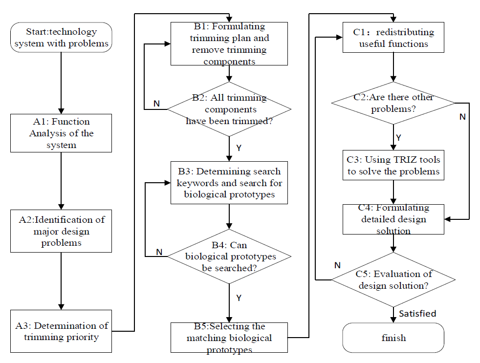
3.1. Analysis before Trimming the System
- Step A1: Analyzing system functions.
- Step A2: Identifying the main design problem.
- Step A3: Determining trimming priorities.
3.2. System Trimming Analysis and System Analysis after Trimming
- Step B1: Formulating the trimming plan and conducting trimming.
- Step B2: Verifying that the identified components have been trimmed.
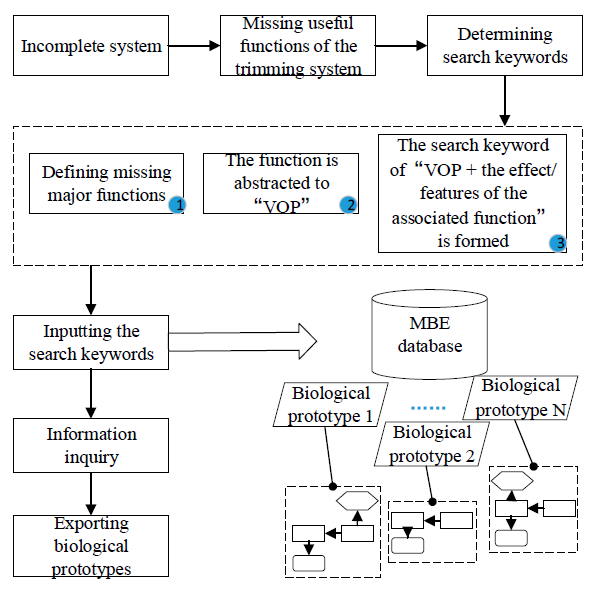
- Step B3: Determining search keywords and searching for biological prototypes.
- (1)
- Search for target functions. These are useful functions that are missing from the trimmed system.
- (2)
- Identify attributes of the target function to describe its characteristics. The target function is described by terms in the form of “V + N” and “V + O + P” (where “V” and “N” refer to specific verbs and nouns, respectively, while “O” and “P” represent abstract objects and attributes).
- (3)
- In order to improve the adaptability and the degree of structural matching between the identified biological prototype and the design system, the effects and features of the missing target functions are expanded according to the associated components removed from the original design system. The search mode “VOP + the effect/features of the associated function” is used for the main keywords.
- Step B4: Verifying that biological prototypes can be identified in the search.
- Step B5: Selecting the best-matching biological prototype.
- B5.1: Establishing the factor set of the comprehensive evaluation.
- B5.2: Determining the weight of each factor and establishing the weight vector set.
- B5.3: Carrying out single-factor fuzzy evaluation and establishing the fuzzy evaluation matrix.
- (1)
- If it acts directly on the product, then the function grade is defined as the basic function, and its grade is ;
- (2)
- If it acts on the basic function, its grade is ;
- (3)
- Functions that act on grade i−1 functions are ;
- (4)
- The function of the super-system is rated .
- (1)
- The function with the lowest function grade has a value equal to 1;
- (2)
- ;
- (3)
- ;
- (4)
- For functions that act on multiple functional components, the rank is the sum of all functions.
- B5.4: Performing fuzzy comprehensive evaluation.
3.3. Innovative Design of the System
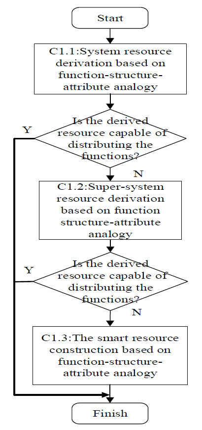
- Step C1: Redistributing useful functions of the system after trimming.
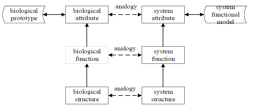
- C1.1: Deriving resources in the system based on structure–function–attribute analogies.
- C1.2: Deriving super-system resources based on structure–function–attribute analogies.
- C1.3: Reconstructing available resources based on structure–function–attribute analogies.
- Step C2: Verifying that all design problems are solved.
- Step C3: Using TRIZ tools to solve remaining problems.
- Step C4: Formulating design solutions.
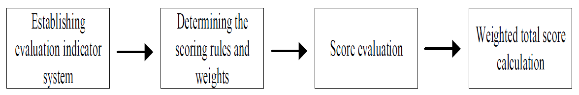
- Step C5: Evaluating the design solution.
- (1)
- Establishing an evaluation indicator system.
- (2)
- Determining the evaluation rules and weights.
- (1)
- The original judgment matrix is normalized according to columns, and is obtained:
- (2)
- The vector is calculated:
- (3)
- is normalized to obtain the feature vectors:
- (4)
- Calculating the total weighted score.
4. Case Study
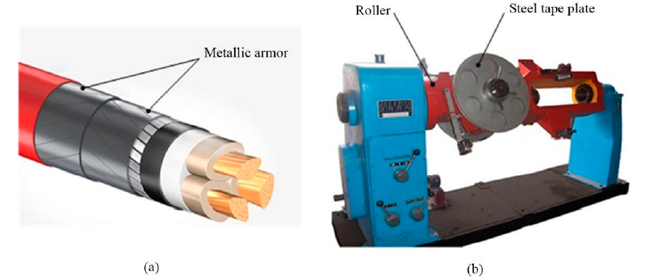
4.1. Analysis of the Steel Tape Armoring Machine before Trimming
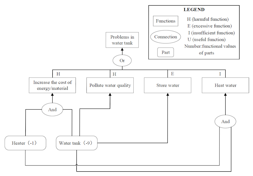
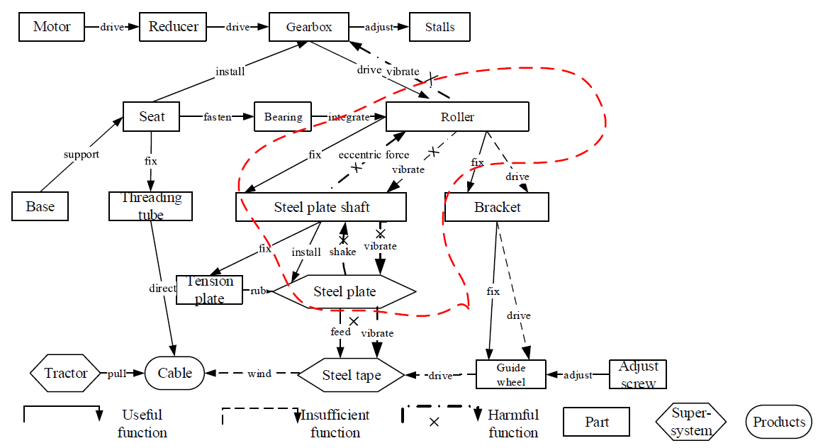
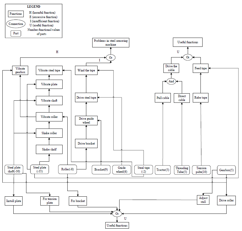
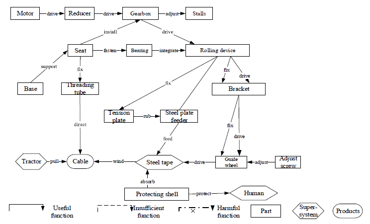
- Step A1: Performing function analysis of the existing steel tape armoring machine.
- Step A2: Identifying major design problems.
- Step A3: Determining trimming priorities.
4.2. The Trimming Analysis of the Steel Tape Armoring Machine and the Analysis of the Device after Trimming
- Step B1: Formulating the trimming plan and trimming the selected components.
- Step B2: Verifying that the designated components have been trimmed.
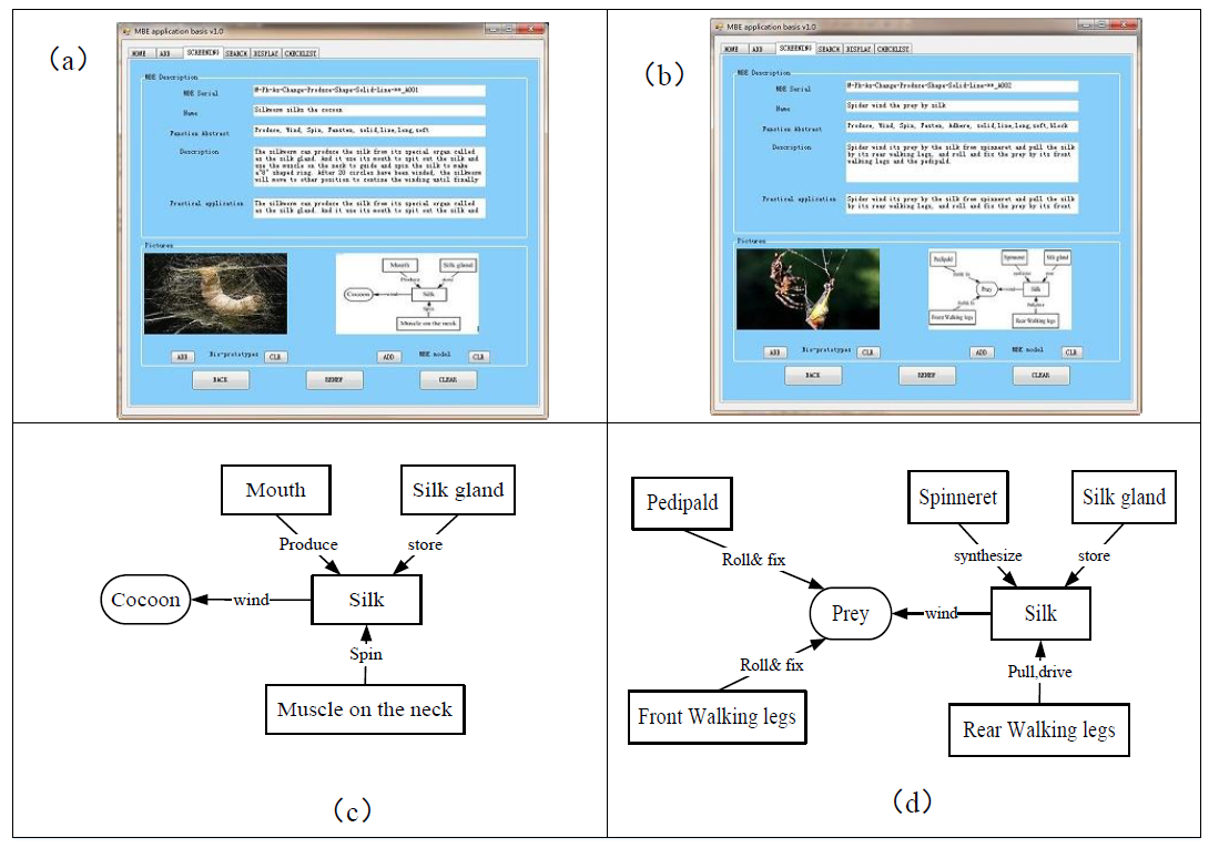
- Steps B3–B4: Determining search keywords and searching for appropriate biological prototypes.
- (1)
- Among the missing useful functions of the steel tape armoring machine determined in the previous step is the target function “feed the steel tape”.
- (2)
- The attribute “feed the steel tape” is characterized by the descriptor “feed long strips of solid material”.
- (3)
- In order to match the adaptability and structure of the steel tape armoring machine with those of the biological prototype, the functional feature of the “winding cable” function is summarized as “winding solid” according to the functional model of the original design. Therefore, the search keyword phrase is “feeding long strip solid, winding around another object”.
- Step B5: Selecting the best-matching biological prototype.
- B5.1–B5.2: The factor set is determined in the form , and the weight vector set is .
- B5.3: Establishing the fuzzy evaluation matrix.
- B5.4: Performing the fuzzy comprehensive evaluation.
4.3. Innovative Design of the Steel Tape Armoring Machine
- Step C1: Redistributing useful functions of the system after trimming.
- C1.1: Deriving resources within the system based on structure–function–component analogies.
- Step C2: Verifying that there are no other design problems in the steel tape armoring machine.
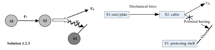
- Step C3: Using TRIZ tools to solve problems.
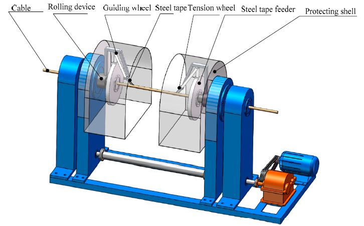
- Step C4: Formulating the design solution.
- Step C5: Evaluating the design solution.
5. Conclusions
Author Contributions
Funding
Conflicts of Interest
Appendix A

| Design Scheme | Project Indicators | Reviewer 1 | Reviewer 2 | Reviewer 3 | Reviewer 4 | Reviewer 5 | Reviewer 6 | Reviewer 7 | The Final Score |
|---|---|---|---|---|---|---|---|---|---|
| Scheme 1 | Increasing the usefulness of functions | 7 | 8 | 7 | 6 | 7 | 6 | 8 | 6.64 |
| Increasing the number of useful functions | 5 | 5 | 6 | 5 | 7 | 5 | 6 | ||
| Improving Product Performance | 7 | 6 | 7 | 8 | 6 | 7 | 6 | ||
| Increasing productivity | 8 | 7 | 7 | 6 | 7 | 7 | 8 | ||
| Scoring results | 6.29 | 6.97 | 6.91 | 6.37 | 6.70 | 6.37 | 6.90 | ||
| Scheme 2 | Increasing the usefulness of functions | 5 | 6 | 5 | 4 | 4 | 6 | 5 | 4.85 |
| Increasing the number of useful functions | 4 | 5 | 5 | 4 | 4 | 5 | 4 | ||
| Improving Product Performance | 5 | 4 | 5 | 4 | 5 | 4 | 4 | ||
| Increasing productivity | 6 | 5 | 5 | 5 | 6 | 6 | 5 | ||
| Scoring results | 5.07 | 5.15 | 5.00 | 4.16 | 4.62 | 5.31 | 4.61 | ||
| Scheme 3 | Increasing the usefulness of functions | 6 | 6 | 7 | 5 | 6 | 7 | 7 | 5.89 |
| Increasing the number of useful functions | 5 | 6 | 5 | 4 | 6 | 5 | 5 | ||
| Improving Product Performance | 6 | 5 | 6 | 7 | 5 | 5 | 6 | ||
| Increasing productivity | 7 | 5 | 6 | 5 | 6 | 5 | 6 | ||
| Scoring results | 6.07 | 5.54 | 6.36 | 5.51 | 5.70 | 5.90 | 6.36 | ||
| Scheme 4 | Increasing the usefulness of functions | 5 | 5 | 6 | 4 | 5 | 5 | 6 | 5.08 |
| Increasing the number of useful functions | 5 | 4 | 4 | 4 | 4 | 5 | 4 | ||
| Improving Product Performance | 6 | 5 | 6 | 5 | 6 | 5 | 4 | ||
| Increasing productivity | 5 | 4 | 5 | 5 | 5 | 6 | 5 | ||
| Scoring results | 5.30 | 4.75 | 5.66 | 4.46 | 5.21 | 5.61 | 4.61 | ||
| Scheme 5 | Increasing the usefulness of functions | 6 | 7 | 6 | 6 | 7 | 6 | 6 | 5.87 |
| Increasing the number of useful functions | 5 | 5 | 5 | 4 | 4 | 5 | 6 | ||
| Improving Product Performance | 7 | 6 | 5 | 6 | 5 | 6 | 5 | ||
| Increasing productivity | 6 | 6 | 5 | 5 | 6 | 5 | 6 | ||
| Scoring results | 6.21 | 6.36 | 5.45 | 5.66 | 5.97 | 5.75 | 5.70 | ||
| Design Scheme | Project Indicators | Reviewer 1 | Reviewer 2 | Reviewer 3 | Reviewer 4 | Reviewer 5 | Reviewer 6 | Reviewer 7 | The Final Score |
|---|---|---|---|---|---|---|---|---|---|
| Scheme 1 | Design cost | 5 | 6 | 5 | 5 | 5 | 6 | 6 | 5.24 |
| Production cost | 5 | 5 | 6 | 5 | 6 | 6 | 5 | ||
| Cost of ancillary facilities | 6 | 5 | 5 | 6 | 5 | 6 | 5 | ||
| Maintenance cost | 5 | 4 | 5 | 6 | 4 | 5 | 6 | ||
| Scoring results | 5.16 | 4.66 | 5.30 | 5.60 | 4.86 | 5.56 | 5.54 | ||
| Scheme 2 | Design cost | 5 | 5 | 6 | 5 | 6 | 5 | 5 | 5.46 |
| Production cost | 6 | 6 | 5 | 6 | 5 | 6 | 5 | ||
| Cost of ancillary facilities | 5 | 5 | 6 | 5 | 5 | 6 | 6 | ||
| Maintenance cost | 5 | 6 | 5 | 5 | 6 | 6 | 5 | ||
| Scoring results | 5.30 | 5.74 | 5.26 | 5.30 | 5.54 | 5.90 | 5.16 | ||
| Scheme 3 | Design cost | 5 | 6 | 5 | 6 | 6 | 5 | 6 | 5.57 |
| Production cost | 6 | 5 | 6 | 5 | 5 | 6 | 6 | ||
| Cost of ancillary facilities | 6 | 6 | 5 | 5 | 6 | 6 | 5 | ||
| Maintenance cost | 6 | 6 | 6 | 5 | 6 | 5 | 6 | ||
| Scoring results | 5.90 | 5.70 | 5.74 | 5.10 | 5.70 | 5.46 | 5.40 | ||
| Scheme 4 | Design cost | 5 | 5 | 6 | 5 | 6 | 5 | 6 | 5.41 |
| Production cost | 6 | 5 | 6 | 6 | 5 | 5 | 5 | ||
| Cost of ancillary facilities | 6 | 6 | 5 | 6 | 6 | 6 | 5 | ||
| Maintenance cost | 5 | 5 | 5 | 5 | 6 | 5 | 6 | ||
| Scoring results | 5.46 | 5.10 | 5.40 | 5.46 | 5.70 | 5.16 | 5.54 | ||
| Scheme 5 | Design cost | 5 | 6 | 5 | 6 | 5 | 5 | 6 | 5.27 |
| Production cost | 6 | 6 | 5 | 6 | 5 | 6 | 5 | ||
| Cost of ancillary facilities | 6 | 5 | 6 | 6 | 6 | 5 | 6 | ||
| Maintenance cost | 5 | 5 | 4 | 5 | 5 | 5 | 5 | ||
| Scoring results | 5.46 | 5.40 | 4.72 | 5.56 | 5.16 | 5.30 | 5.26 | ||
| Design Scheme | Project Indicators | Reviewer 1 | Reviewer 2 | Reviewer 3 | Reviewer 4 | Reviewer 5 | Reviewer 6 | Reviewer 7 | The Final Score |
|---|---|---|---|---|---|---|---|---|---|
| Scheme 1 | Reducing the degree of harmful function | 7 | 7 | 6 | 7 | 8 | 7 | 6 | 5.46 |
| Reducing the number of harmful functions | 6 | 7 | 6 | 6 | 7 | 6 | 7 | ||
| Existing pollution | 5 | 6 | 5 | 6 | 5 | 5 | 6 | ||
| Existing risk | 4 | 5 | 4 | 4 | 5 | 4 | 5 | ||
| Scoring results | 5.11 | 5.97 | 4.97 | 5.64 | 5.58 | 5.11 | 5.83 | ||
| Scheme 2 | Reducing the degree of harmful function | 4 | 5 | 4 | 4 | 5 | 5 | 4 | 6.37 |
| Reducing the number of harmful functions | 5 | 6 | 5 | 5 | 4 | 6 | 5 | ||
| Existing pollution | 8 | 7 | 7 | 8 | 8 | 7 | 7 | ||
| Existing risk | 6 | 5 | 6 | 6 | 6 | 5 | 5 | ||
| Scoring results | 6.70 | 6.14 | 6.17 | 6.70 | 6.76 | 6.11 | 5.92 | ||
| Scheme 3 | Reducing the degree of harmful function | 5 | 4 | 4 | 5 | 4 | 5 | 4 | 5.28 |
| Reducing the number of harmful functions | 5 | 5 | 6 | 5 | 6 | 5 | 5 | ||
| Existing pollution | 5 | 6 | 5 | 5 | 6 | 6 | 5 | ||
| Existing risk | 6 | 6 | 5 | 6 | 5 | 5 | 6 | ||
| Scoring results | 5.25 | 5.64 | 4.94 | 5.00 | 5.47 | 5.53 | 5.11 | ||
| Scheme 4 | Reducing the degree of harmful function | 5 | 5 | 4 | 5 | 4 | 5 | 5 | 5.86 |
| Reducing the number of harmful functions | 5 | 4 | 5 | 5 | 6 | 5 | 5 | ||
| Existing pollution | 7 | 6 | 7 | 7 | 6 | 6 | 7 | ||
| Existing risk | 6 | 5 | 5 | 5 | 6 | 5 | 5 | ||
| Scoring results | 6.31 | 5.45 | 5.92 | 6.06 | 5.72 | 5.53 | 6.06 | ||
| Scheme 5 | Reducing the degree of harmful function | 4 | 5 | 5 | 4 | 5 | 6 | 5 | 5.61 |
| Reducing the number of harmful functions | 5 | 5 | 6 | 5 | 5 | 5 | 6 | ||
| Existing pollution | 6 | 6 | 5 | 7 | 6 | 5 | 6 | ||
| Existing risk | 5 | 6 | 6 | 5 | 6 | 6 | 5 | ||
| Scoring results | 5.39 | 5.78 | 5.53 | 5.96 | 5.78 | 5.39 | 5.61 | ||
References
- Xu, D.L. TRIZ Innovative Tools; Ding Mao Book Publishing Co. Ltd.: Taibei, Taiwan, 2010; pp. 143–182. [Google Scholar]
- Litvin, S.S. Types of Psychological Inertia. In Proceedings of the MATRIZ TRIZ Fest 2016 International Conference, Beijing, China, 28–30 July 2016; pp. 401–406. [Google Scholar]
- Zhang, E.J.; Yu, F.; Yang, B.J.; Shi, W.G.; Li, Z.G. Research on trimming aroused by knowledge oriented for design requirements. J. Mech. Des. 2018, 35, 40–46. [Google Scholar]
- Sheu, D.D.; Hou, C.T. TRIZ-based trimming for process-machine improvements: Slit-valve innovative redesign. Comput. Ind. Eng. 2013, 66, 555–566. [Google Scholar] [CrossRef]
- Yu, F.; Liu, F.; Tan, R.H.; Liu, Z.G. Construction of Multi-level Trimming Method Set Based on TRIZ. J. Mech. Eng. 2015, 51, 156–164. [Google Scholar] [CrossRef]
- Helms, M.; Vattam, S.S.; Goel, A.K. Biologically inspired design: Process and products. Des. Stud. 2009, 30, 606–622. [Google Scholar] [CrossRef]
- Nagel, J.K.S.; Stone, R.B.; McAdams, D.A. Biologically Inspired Design; Springer: London, UK, 2014. [Google Scholar] [CrossRef]
- Goel, A.K.; Vattam, S.; Wiltgen, B. Cognitive, collaborative, conceptual and creative—Four characteristics of the next generation of knowledge-based CAD systems: A study in biologically inspired design. Comput. Aided Des. 2012, 44, 879–900. [Google Scholar] [CrossRef]
- Chirazi, J.; Wanieck, K.; Fayemi, P.E.; Zollfrank, C.; Jacobs, S. What Do We Learn from Good Practices of Biologically Inspired Design in Innovation? Appl. Sci. 2019, 9, 650. [Google Scholar] [CrossRef]
- Vattam, S.; Wiltgen, B.; Helms, M.; Goel, A.K.; Yen, J. DANE: Fostering Creativity in and through Biologically Inspired Design. In Design Creativity; Springer: London, UK, 2011; pp. 115–122. [Google Scholar] [CrossRef]
- Liu, W.; Cao, G.Z.; Tan, R.H. Research on measures to technical realization of multi biological effects. J. Mech. Eng. 2016, 52, 129–140. [Google Scholar] [CrossRef]
- Vandevenne, D.; Pieters, T.; Duflou, J.R. Enhancing novelty with knowledge-based support for Biologically-Inspired Design. Des. Stud. 2016, 46, 152–173. [Google Scholar] [CrossRef]
- Glier, M.W.; Tsenn, J.; Linsey, J.S.; Mcadams, D.A. Evaluating the Directed Intuitive Approach for Bioinspired Design. J. Mech. Des. 2014, 136, 071012. [Google Scholar] [CrossRef]
- Li, M.; Ming, X.; He, L.; Zheng, M.K.; Xu, Z.T. A TRIZ-based Trimming method for Patent design around. Comput. Aided Des. 2015, 62, 20–30. [Google Scholar] [CrossRef]
- Bariani, P.F.; Berti, G.A.; Lucchetta, G. A Combined DFMA and TRIZ Approach to the Simplification of Product Structure. Proc. IMechE Part B J. Eng. Manuf. 2004, 218, 1023–1027. [Google Scholar] [CrossRef]
- Li, M.; Ming, X.; Zheng, M.; Xu, Z.T.; He, L. A framework of product innovative design process based on TRIZ and Patent Circumvention. J. Eng. Des. 2013, 24, 830–848. [Google Scholar] [CrossRef]
- Gadd, K. TRIZ for Engineers: Enabling Inventive Problem Solving; John Wiley & Sons: Hoboken, NJ, USA; Wiley-Blackwell: London, UK, 2011. [Google Scholar]
- Ikovenko, S.; Bradley, J. TRIZ as A Lean Thinking Tool. In Proceedings of the TRIZ Future 4th World Conference, Florence, Italy, 3–5 November 2004; pp. 157–163. [Google Scholar]
- Mann, D. Hands on Systematic Innovation; CREAX Press: Brussels, Belgium, 2002. [Google Scholar]
- Lin, Y.; Sheu, D.D. TRIZ-Based Computer-Aided Trimming Process and Tool. Master’s Thesis, National Tsing Hua University, Hsinchu, Taiwan, 2010. [Google Scholar]
- Efimov-Soini, N.K.; Chechurin, L.S. Method of Ranking in the Function Model. Procedia CIRP 2016, 39, 22–26. [Google Scholar] [CrossRef]
- Yu, F.; Tan, R.; Cao, G.; Jiang, P. Study on trimming priority based on system functional model. Comput. Integr. Manuf. Syst. 2013, 19, 338–347. [Google Scholar]
- Sheu, D.D.; Tsai, M. Cause Effect and Contradiction Chain Analysis for Conflict Identification and Problem Solving. In Proceedings of the 2nd International Conference on Systematic Innovation, Shanghai, China, 26–28 May 2012. [Google Scholar]
- Sheu, D.D.; Hong, J.; Ho, C. New product identification and design through super-system trimming. Comput. Ind. Eng. 2017, 111, 251–262. [Google Scholar] [CrossRef]
- San, Y.T. TRIZ—Systematic Innovation in Manufacturing; Firstfruits Sdn Bhd.: Kuala Lumpur, Malaysia, 2009; pp. 43–49. [Google Scholar]
- Zhu, Y. A Study on Integrating TRIZ Method with Functional Analysis. Master’s Thesis, Taiwan Cheng Kung University, Tainan City, Taiwan, 2003. [Google Scholar]
- Grawatsch, M. Module 3 of the Support Training Course; Montan University: Leoben, Austria, 2005. [Google Scholar]
- Petr, K.; Victor, F.; Mann, D.L. TRIZ Power Tool-Simplifying; Third Millennium Publishing: Tempe, AZ, USA, 2012; pp. 27–45. [Google Scholar]
- Efimov-Soini, N.; Elfvengren, K. A Method of System Model Improvement Using TRIZ Function Analysis and Trimming. Advances in Systematic Creativity Creating and Managing Innovation; Palgrave Macmillan: Cham, Switzerland, 2018; pp. 115–131. [Google Scholar]
- Boavida, R.; Navas, H.; Godina, R.; Carvalho, H.; Hasegawa, H. A combined use of TRIZ methodology and eco-compass tool as a sustainable innovation model. Appl. Sci. 2020, 10, 3535. [Google Scholar] [CrossRef]
- Wilson, J.O.; Rosen, D.; Nelson, B.A.; Yen, J. The effects of biological examples in idea generation. Des. Stud. 2010, 31, 169–186. [Google Scholar] [CrossRef]
- Anastas, P.T.; Warner, J.C. Green Chemistry: Theory and Practice; Oxford University Press: London, UK, 2000. [Google Scholar]
- Forbes, P. The Gecko’s Foot: Bio-Inspiration: Engineering New Materials from Nature; WW Norton & Co: New York, NY, USA, 2006. [Google Scholar]
- Bonser, R.H. Patented biologically-inspired technological innovations: A twenty year view. J. Bionic Eng. 2006, 3, 39–41. [Google Scholar] [CrossRef]
- Nagel, J.K.S.; Nagel, R.L.; Stone, R.B.; Mcadams, D.A. Function-based, biologically inspired concept generation. Artif. Intell. Eng. Des. Anal. Manuf. 2010, 24, 521–535. [Google Scholar] [CrossRef]
- Chakrabarti, A.; Sarkar, P.; Leelavathamma, B.; Nataraju, B.S. A functional representation for aiding biomimetic and artificial inspiration of new ideas. Artif. Intell. Eng. Des. Anal. Manuf. 2005, 19, 113–132. [Google Scholar] [CrossRef]
- Hirtz, J.; Stone, R.B.; Mcadams, D.A.; Szykman, S.; Wood, K.L. A Functional Basis for Engineering Design: Reconciling and Evolving Previous Efforts. Res. Eng. Des. 2002, 13, 65–82. [Google Scholar] [CrossRef]
- Nagel, J.K.S.; Nagel, R.L.; Stone, R.B. Abstracting biology for engineering design. Int. J. Des. Eng. 2011, 4, 23–40. [Google Scholar] [CrossRef]
- Vincent, J.F.V.; Bogatyreva, O.A.; Bogatyrev, N.R.; Bowyer, A.; Pahl, A.K. Biomimetics: Its practice and theory. J. R. Soc. Interface 2006, 3, 471–482. [Google Scholar] [CrossRef]
- Baldussu, A.; Cascini, G. About integration opportunities between TRIZ and biomimetics for inventive design. Procedia Eng. 2015, 131, 3–13. [Google Scholar] [CrossRef]
- Bogatyreva, O.; Bogatyrev, N. Complexity in Living and Non-Living Systems. In Proceedings of the International TRIZ Conference, Philadelphia, PA, USA, 16–18 March 2003; p. 16. [Google Scholar]
- Ren, L.Q.; Liang, Y.H. Biological couplings: Classification and characteristic rules. Sci. China Technol. Sci. 2009, 52, 2791–2800. [Google Scholar] [CrossRef]
- Nagel, J.K.S.; Stone, R.B.; Mcadams, D.A. An Engineering-to-Biology Thesaurus for Engineering Design. In Proceedings of the ASME 2010 International Design Engineering Technical Conferences and Computers and Information in Engineering Conference, Montreal, QC, Canada, 15–18 August 2010; pp. 117–128. [Google Scholar]
- Pahl, G.; Beitz, W.; Feldhusen, J.A.; Grote, K.H. Engineering Design: A Systematic Approach; Institution of Engineering and Technology (IET): London, UK, 1963; p. 63. [Google Scholar]
- Pandremenos, J.; Vasiliadis, E.; Chryssolouris, G. Design architectures in biology. Proc. CIRP 2012, 3, 448–452. [Google Scholar] [CrossRef][Green Version]
- Ulrich, K.T.; Seering, W.P. Function Sharing in Mechanical Design. Des. Stud. 1990, 11, 223–234. [Google Scholar] [CrossRef]
- Singh, V.; Skiles, S.M.; Krager, J.E.; Wood, K.L.; Jensen, D.; Sierakowski, R. Innovations in Design Through Transformation: A Fundamental Study of Transformation Principles. J. Mech. Des. 2009, 131, 081010. [Google Scholar] [CrossRef]
- Bhasin, D.; Behmer, S.T.; McAdams, D.A. Fostering Function-Sharing Using Bioinspired Product Architecture. J. Mech. Des. 2021, 143, 061401. [Google Scholar] [CrossRef]
- Bhasin, D.; McAdams, D.A.; Layton, A. A product architecture-based tool for bioinspired function-sharing. J. Mech. Des. 2021, 143, 081401. [Google Scholar] [CrossRef]
- Liu, X.M.; Wang, J.H.; Li, J.R.; Chen, L. Product Innovation Design Based on Biological Prototype. Chin. J. Eng. Mach. 2017, 15, 504–512. (In Chinese) [Google Scholar]
- Zhou, M.L. Similar systems engineering. Syst. Eng. Theory Pract. 1997, 9, 37–43. (In Chinese) [Google Scholar]
- Wei, C.C.; Chien, C.F.; Wang, M.J.J. An AHP-based approach to ERP system selection. Int. J. Prod. Econ. 2005, 96, 47–62. [Google Scholar] [CrossRef]
- Tan, R.H. TRIZ and Applications—The Process and Methods of Technological Innovation; Higher Education Press: Beijing, China, 2010. [Google Scholar]
- Li, H.S.; Jin, Q.C.; Wang, Q.; Yue, R.; Hu, Y. Performance Evaluation of tour Car Mechanical System Based on Grey AHP. Mach. Build. Autom. 2015, 44, 63–66. (In Chinese) [Google Scholar]
- Cao, G.Z.; Mu, B.; Wan, Z.W.; Guo, X.F. Research on the Design Process of Self-service Products Based on Ideal Solution. J. Machanical. Des. 2020, 37, 134–139. (In Chinese) [Google Scholar]
- Bertolini, M.; Braglia, M.; Carmignani, G. Application of the AHP methodology in making a proposal for a public work contract. Int. J. Proj. Manag. 2006, 24, 422–430. [Google Scholar] [CrossRef]
- Shi, W.G.; Yang, B.J.; Yu, F.; Li, Z.W.; Zhang, E.J. Research on cutting method based on technological evolution trend. J. Eng. Des. 2016, 23, 301–308. (In Chinese) [Google Scholar]
- Liu, W.; Tan, R.H.; Peng, Q.J.; Li, H.; Li, Z.B.; Yang, B.J. Impact of TRIZ Learning on Performance in Biologically Inspired Design. Int. J. Eng. Educ. 2020, 36, 974–987. [Google Scholar]


| Name of the Element | Function Grade Values | Weight Values (Normalized Results) |
|---|---|---|
| Function 1 | ||
| Function 2 | ||
| Function 3 | ||
| ... | ... | ... |
| Function n |
| The Value of | Meaning |
|---|---|
| 0.2 | Two similar functions are generally not similar |
| 0.4 | Two similar functions are slightly similar |
| 0.6 | Two similar functions are relatively similar |
| 0.8 | Two similar functions are very similar |
| 1 | Two similar functions are completely identical |
| Factor | Evaluation Level | |||
|---|---|---|---|---|
| Completeness | Independent execution | Non-independent execution | ||
| 1 | 0 | |||
| Feasibility | Normal function | Partially normal function | Non-normal function | |
| 1 | 0.5 | 0 | ||
| Target Layer | Comprehensive Indicator Layer (Weight Value) | Project Indicator Layer (Weight Value) |
|---|---|---|
| System ideality | U1 benefits (0.66) | U11 Increasing the usefulness of functions (0.45) |
| U12 Increasing the number of useful functions (0.09) | ||
| U13 Improving Product Performance (0.30) | ||
| U14 Increasing productivity (0.16) | ||
| U2 costs (0.11) | U21 Design cost (0.10) | |
| U22 Production cost (0.30) | ||
| U23 Cost of ancillary facilities (0.16) | ||
| U24 Maintenance cost (0.44) | ||
| U3 harms (0.23) | U31 Reducing the degree of harmful functions (0.14) | |
| U32 Reducing the number of harmful functions (0.08) | ||
| U33 Existing pollution (0.53) | ||
| U34 Existing risk (0.25) |
| Description | Very Good | Good | Moderate | Not Very Good | Not Good | Very Bad |
|---|---|---|---|---|---|---|
| Score | 9–10 | 7–8 | 5–6 | 3–4 | 1–2 | 0–1 |
| Meaning | and Equally Important | and Slightly Important | and Important | and Quite Important | and Extremely Important |
|---|---|---|---|---|---|
| 1 | 3 | 5 | 7 | 9 |
| Component | Useful Function | Insufficient Function | Excessive Function | Harmful Function | Function Value | Rank | ||||||||
|---|---|---|---|---|---|---|---|---|---|---|---|---|---|---|
| Fi | Li | Ti | Fi | Li | Ti | Fi | Li | Ti | Fi | Li | Ti | |||
| Plate Shaft | 5 | 1 | (1 + 1) | - | - | - | - | - | - | −5 | 1 | (3 + 5) | −30 | 2 |
| Steel plate | 5 | 1 | 1 | - | - | - | - | - | - | −5 | 1 | (2 + 6) | −35 | 1 |
| Roller | 5 | 1 | 1 | 3 | 1 | 4 | - | - | - | −5 | 1 | 5 | −8 | 3 |
| Gearbox | 5 | 1 | 1 + 1 | - | - | - | - | - | - | −5 | 1 | 1 | 5 | 4 |
| Bracket | - | - | - | 3 | 1 | 3 | - | - | - | - | - | - | 9 | 6 |
| Guide wheel | - | - | - | 3 | 1 | 2 | - | - | - | - | - | - | 6 | 5 |
| Steel tape * | - | - | - | 3 | 1 | 1 | - | - | - | −5 | 1 | 1 | −2 | - |
| Tractor * | 5 | 0.5 | 2 | - | - | - | - | - | - | - | - | - | 5 | - |
| Threading tube | 5 | 0.5 | 2 | - | - | - | - | - | - | - | - | - | 5 | 4 |
| Tension plate | 5 | 1 | 2 | - | - | - | - | - | - | - | - | - | 10 | 7 |
| The Names of the Function | Function Grade Values | Weight Values (Normalized Results) |
|---|---|---|
| roll fix prey 1 | B--3 | 0.25 |
| roll fix prey 2 | B--3 | 0.25 |
| synthesize silk | A1--1 | 0.08 |
| pull and drive silk | A1--1 | 0.08 |
| store silk | A1--1 | 0.08 |
| wind cocoon | B--3 | 0.25 |
| The Names of the Function | Function Grade Values | Weight Values (Normalized Results) |
|---|---|---|
| produce silk | A1--1 | 0.17 |
| store silk | A1--1 | 0.17 |
| spin silk | A1--1 | 0.17 |
| wind cocoon | B--3 | 0.50 |
| Design Scheme | Scheme 3 [57] | Scheme 4 | Scheme 5 |
|---|---|---|---|
| Description of the Scheme | A steel tape armoring machine containing brackets, a guide wheel, a steel tape plate, steel tape, a cable, a roller and other structures. The steel tape plate traverses the roller, which can eliminate the influence of vibration and noise. The roller performs the function of the steel tape plate shaft to provide support and rotation. Its advantages include simple structure, high production efficiency, low noise, etc. | A self-interlocking armoring machine for submersible pump cables, including the main body of the armoring machine, the inlet frame, the outlet frame, the guide wheel, the limiting pulley, the active mixing wheel and the limiting ring. It solves the problems of cable wear and non-adjustable cable height due to the different import heights of cables and devices. | An interlocking armoring machine that includes a bottom plate, support column, top cover, fixed ring, support pipe, storage plate, installation frame, rotary motor, transmission belt, fixed turntable, fixed crossbar, auxiliary ring and other structures. The top cover can be opened and closed, which is convenient for installation, disassembling and maintenance. The limit wheel limits the conveyor belt to effectively prevent it from falling off. The machine is characterized by reduced labor, quick replacement, high efficiency, and a simple and stable structure. |
| Picture of the Scheme |  |  |  |
| Comprehensive Evaluation Indicator | Scheme 1 | Scheme 2 | Scheme 3 [57] | Scheme 4 | Scheme 5 |
|---|---|---|---|---|---|
| Benefits | 6.64 | 4.85 | 5.89 | 5.08 | 5.87 |
| Expenses | 5.24 | 5.46 | 5.57 | 5.41 | 5.27 |
| Harms | 5.46 | 6.37 | 5.28 | 5.86 | 5.61 |
| The final score for ideality | 6.34 | 5.27 | 5.71 | 5.30 | 5.74 |
Publisher’s Note: MDPI stays neutral with regard to jurisdictional claims in published maps and institutional affiliations. |
© 2021 by the authors. Licensee MDPI, Basel, Switzerland. This article is an open access article distributed under the terms and conditions of the Creative Commons Attribution (CC BY) license (https://creativecommons.org/licenses/by/4.0/).
Share and Cite
Zhang, P.; Li, X.; Nie, Z.; Yu, F.; Liu, W. A Trimming Design Method Based on Bio-Inspired Design for System Innovation. Appl. Sci. 2021, 11, 4060. https://doi.org/10.3390/app11094060
Zhang P, Li X, Nie Z, Yu F, Liu W. A Trimming Design Method Based on Bio-Inspired Design for System Innovation. Applied Sciences. 2021; 11(9):4060. https://doi.org/10.3390/app11094060
Chicago/Turabian StyleZhang, Peng, Xindi Li, Zifeng Nie, Fei Yu, and Wei Liu. 2021. "A Trimming Design Method Based on Bio-Inspired Design for System Innovation" Applied Sciences 11, no. 9: 4060. https://doi.org/10.3390/app11094060
APA StyleZhang, P., Li, X., Nie, Z., Yu, F., & Liu, W. (2021). A Trimming Design Method Based on Bio-Inspired Design for System Innovation. Applied Sciences, 11(9), 4060. https://doi.org/10.3390/app11094060