
Preparation and Application of ZIF-8 Thin Layers

 ,
,
Abstract
1. Introduction
2. Materials and Methods
2.1. Electrochemical Anodic Deposition
2.2. Doctor Blade Technique for PVDF Layer
2.3. Doctor Blade Technique for Composite Layer Containing PVDF Binder and ZIF-8
2.4. Successive Two-Layer Composite, Containing a PVDF-Film and a ZIF-8 Film
2.5. Contact Angle Measurements
2.6. Further Methodes
2.6.1. SEM
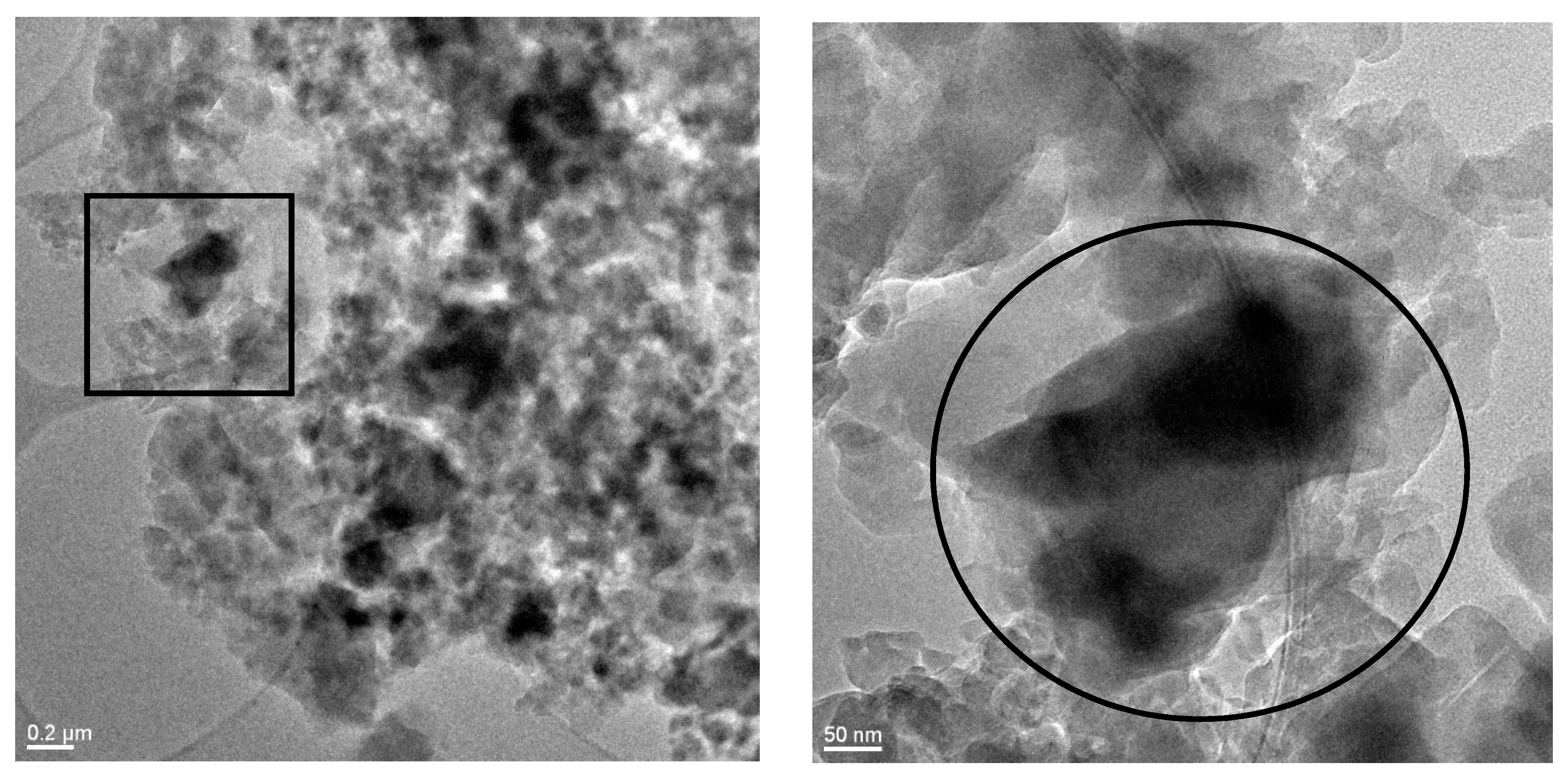
2.6.2. TEM
2.6.3. XRD
2.6.4. Optical Profilometry
3. Results
3.1. Electrochemical Thin Layer Deposition and Effect of Synthesis Conditions
3.1.1. Linker Concentration
3.1.2. Electrochemical Potential
3.1.3. Synthesis Duration
3.1.4. Electrolyte Composition
3.2. Doctor Blade Technique for Composite Layer Containing PVDF Binder and ZIF-8
3.3. Surface Roughness Studies
3.4. Wetting Properties
4. Discussion
5. Conclusions
Supplementary Materials
Author Contributions
Funding
Institutional Review Board Statement
Informed Consent Statement
Data Availability Statement
Acknowledgments
Conflicts of Interest
References
- Epstein, A.K.; Wong, T.-S.; Belisle, R.A.; Boggs, E.M.; Aizenberg, J. Liquid-infused structured surfaces with exceptional anti-biofouling performance. Proc. Natl. Acad. Sci. USA 2012, 109, 13182–13187. [Google Scholar] [CrossRef] [PubMed]
- Tesler, A.B.; Kim, P.; Kolle, S.; Howell, C.; Ahanotu, O.; Aizenberg, J. Extremely durable biofouling-resistant metallic surfaces based on electrodeposited nanoporous tungstite films on steel. Nat. Commun. 2015, 6, 8649. [Google Scholar] [CrossRef] [PubMed]
- Xiao, L.; Li, J.; Mieszkin, S.; Di Fino, A.; Clare, A.S.; Callow, M.E.; Callow, J.A.; Grunze, M.; Rosenhahn, A.; Levkin, P.A. Slippery liquid-infused porous surfaces showing marine antibiofouling properties. ACS Appl. Mater. Interfaces 2013, 5, 10074–10080. [Google Scholar] [CrossRef]
- Wilson, P.W.; Lu, W.; Xu, H.; Kim, P.; Kreder, M.J.; Alvarenga, J.; Aizenberg, J. Inhibition of ice nucleation by slippery liquid-infused porous surfaces (SLIPS). Phys. Chem. Chem. Phys. 2013, 15, 581–585. [Google Scholar] [CrossRef]
- Kim, P.; Wong, T.-S.; Alvarenga, J.; Kreder, M.J.; Adorno-Martinez, W.E.; Aizenberg, J. Liquid-infused nanostructured surfaces with extreme anti-ice and anti-frost performance. ACS Nano 2012, 6, 6569–6577. [Google Scholar] [CrossRef]
- Lafuma, A.; Quéré, D. Slippery pre-suffused surfaces. EPL 2011, 96, 56001. [Google Scholar] [CrossRef]
- Wang, Y.; Zhang, H.; Liu, X.; Zhou, Z. Slippery liquid-infused substrates: A versatile preparation, unique anti-wetting and drag-reduction effect on water. J. Mater. Chem. A 2016, 4, 2524–2529. [Google Scholar] [CrossRef]
- Kota, A.K.; Kwon, G.; Tuteja, A. The design and applications of superomniphobic surfaces. NPG Asia Mater. 2014, 6, e109. [Google Scholar] [CrossRef]
- Howell, C.; Grinthal, A.; Sunny, S.; Aizenberg, M.; Aizenberg, J. Designing Liquid-Infused Surfaces for Medical Applications: A Review. Adv. Mater. 2018, 30, e1802724. [Google Scholar] [CrossRef] [PubMed]
- Sun, Y.; Guo, Z. Recent advances of bioinspired functional materials with specific wettability: From nature and beyond nature. Nanoscale Horiz. 2019, 4, 52–76. [Google Scholar] [CrossRef]
- Villegas, M.; Zhang, Y.; Abu Jarad, N.; Soleymani, L.; Didar, T.F. Liquid-Infused Surfaces: A Review of Theory, Design, and Applications. ACS Nano 2019, 13, 8517–8536. [Google Scholar] [CrossRef] [PubMed]
- Tuteja, A.; Choi, W.; Ma, M.; Mabry, J.M.; Mazzella, S.A.; Rutledge, G.C.; McKinley, G.H.; Cohen, R.E. Designing superoleophobic surfaces. Science 2007, 318, 1618–1622. [Google Scholar] [CrossRef]
- Kota, A.K.; Choi, W.; Tuteja, A. Superomniphobic surfaces: Design and durability. MRS Bull. 2013, 38, 383–390. [Google Scholar] [CrossRef]
- Wier, K.A.; McCarthy, T.J. Condensation on ultrahydrophobic surfaces and its effect on droplet mobility: Ultrahydrophobic surfaces are not always water repellant. Langmuir 2006, 22, 2433–2436. [Google Scholar] [CrossRef]
- Narhe, R.D.; Beysens, D.A. Water condensation on a super-hydrophobic spike surface. EPL 2006, 75, 98–104. [Google Scholar] [CrossRef]
- Sablowski, J.; Unz, S.; Beckmann, M. Dropwise Condensation on Advanced Functional Surfaces—Theory and Experimental Setup. Chem. Eng. Technol. 2017, 40, 1966–1974. [Google Scholar] [CrossRef]
- Wong, T.-S.; Kang, S.H.; Tang, S.K.Y.; Smythe, E.J.; Hatton, B.D.; Grinthal, A.; Aizenberg, J. Bioinspired self-repairing slippery surfaces with pressure-stable omniphobicity. Nature 2011, 477, 443–447. [Google Scholar] [CrossRef]
- Bauer, S.; Stock, N. MOFs—Metallorganische Gerüststrukturen. Funktionale poröse Materialien. Chem. Unserer Zeit 2008, 42, 12–19. [Google Scholar] [CrossRef]
- Batten, S.R.; Champness, N.R.; Chen, X.-M.; Garcia-Martinez, J.; Kitagawa, S.; Öhrström, L.; O’Keeffe, M.; Paik Suh, M.; Reedijk, J. Terminology of metal–organic frameworks and coordination polymers (IUPAC Recommendations 2013). Pure Appl. Chem. 2013, 85, 1715–1724. [Google Scholar] [CrossRef]
- Doan, H.V.; Amer Hamzah, H.; Karikkethu Prabhakaran, P.; Petrillo, C.; Ting, V.P. Hierarchical Metal–Organic Frameworks with Macroporosity: Synthesis, Achievements, and Challenges. Nano-Micro Lett. 2019, 11. [Google Scholar] [CrossRef]
- Phan, A.; Doonan, C.J.; Uribe-Romo, F.J.; Knobler, C.B.; O’Keeffe, M.; Yaghi, O.M. Synthesis, structure, and carbon dioxide capture properties of zeolitic imidazolate frameworks. Acc. Chem. Res. 2010, 43, 58–67. [Google Scholar] [CrossRef] [PubMed]
- Stassen, I.; Campagnol, N.; Fransaer, J.; Vereecken, P.; de Vos, D.; Ameloot, R. Solvent-free synthesis of supported ZIF-8 films and patterns through transformation of deposited zinc oxide precursors. CrystEngComm 2013, 15, 9308. [Google Scholar] [CrossRef]
- Cruz, A.J.; Stassen, I.; Krishtab, M.; Marcoen, K.; Stassin, T.; Rodríguez-Hermida, S.; Teyssandier, J.; Pletincx, S.; Verbeke, R.; Rubio-Giménez, V.; et al. Integrated Cleanroom Process for the Vapor-Phase Deposition of Large-Area Zeolitic Imidazolate Framework Thin Films. Chem. Mater. 2019, 31, 9462–9471. [Google Scholar] [CrossRef]
- Stassen, I.; Styles, M.; Grenci, G.; van Gorp, H.; Vanderlinden, W.; de Feyter, S.; Falcaro, P.; de Vos, D.; Vereecken, P.; Ameloot, R. Chemical vapour deposition of zeolitic imidazolate framework thin films. Nat. Mater. 2016, 15, 304–310. [Google Scholar] [CrossRef] [PubMed]
- Oozeerally, R.; Ramkhelawan, S.D.K.; Burnett, D.L.; Tempelman, C.H.L.; Degirmenci, V. ZIF-8 Metal Organic Framework for the Conversion of Glucose to Fructose and 5-Hydroxymethyl Furfural. Catalysts 2019, 9, 812. [Google Scholar] [CrossRef]
- Lu, G.; Hupp, J.T. Metal-organic frameworks as sensors: A ZIF-8 based Fabry-Pérot device as a selective sensor for chemical vapors and gases. J. Am. Chem. Soc. 2010, 132, 7832–7833. [Google Scholar] [CrossRef] [PubMed]
- Kwon, H.T.; Jeong, H.-K.; Lee, A.S.; An, H.S.; Lee, J.S. Heteroepitaxially grown zeolitic imidazolate framework membranes with unprecedented propylene/propane separation performances. J. Am. Chem. Soc. 2015, 137, 12304–12311. [Google Scholar] [CrossRef]
- Mueller, U.; Schubert, M.; Teich, F.; Puetter, H.; Schierle-Arndt, K.; Pastré, J. Metal–organic frameworks—Prospective industrial applications. J. Mater. Chem. 2006, 16, 626–636. [Google Scholar] [CrossRef]
- Al-Kutubi, H.; Gascon, J.; Sudhölter, E.J.R.; Rassaei, L. Electrosynthesis of Metal-Organic Frameworks: Challenges and Opportunities. Chemelectrochem 2015, 2, 462–474. [Google Scholar] [CrossRef]
- Ameloot, R.; Stappers, L.; Fransaer, J.; Alaerts, L.; Sels, B.F.; de Vos, D.E. Patterned Growth of Metal-Organic Framework Coatings by Electrochemical Synthesis. Chem. Mater. 2009, 21, 2580–2582. [Google Scholar] [CrossRef]
- Yadnum, S.; Roche, J.; Lebraud, E.; Négrier, P.; Garrigue, P.; Bradshaw, D.; Warakulwit, C.; Limtrakul, J.; Kuhn, A. Site-Selective Synthesis of Janus-type Metal-Organic Framework Composites. Angew. Chem. 2014, 126, 4082–4086. [Google Scholar] [CrossRef]
- Varsha, M.V.; Nageswaran, G. Review—Direct Electrochemical Synthesis of Metal Organic Frameworks. J. Electrochem. Soc. 2020, 167, 155527. [Google Scholar] [CrossRef]
- Sablowski, J.; Linnemann, J.; Hempel, S.; Hoffmann, V.; Unz, S.; Beckmann, M.; Giebeler, L. Electrodeposited metal-organic framework films as self-assembled hierarchically superstructured supports for stable omniphobic surface coatings. Sci. Rep. 2018, 8, 15400. [Google Scholar] [CrossRef]
- Cha, H.; Vahabi, H.; Wu, A.; Chavan, S.; Kim, M.-K.; Sett, S.; Bosch, S.A.; Wang, W.; Kota, A.K.; Miljkovic, N. Dropwise condensation on solid hydrophilic surfaces. Sci. Adv. 2020, 6, eaax0746. [Google Scholar] [CrossRef] [PubMed]
- Park, K.S.; Ni, Z.; Cote, A.P.; Choi, J.Y.; Huang, R.; Uribe-Romo, F.J.; Chae, H.K.; O’Keeffe, M.; Yaghi, O.M. CCDC 602542: Experimental Crystal Structure Determination; The Cambridge Crystallographic Data Centre: Cambridge, UK, 2006. [Google Scholar]
- Strandberg, H.; Langer, V.; Johansson, L.-G.; Bálint, J.; Fogassy, E.; Christensen, L.K.; Napoli, A.; Sindona, G.; Aksnes, D.W.; Francis, G.W.; et al. Structure of Cu2.5(OH)3SO4.2H2O: A Novel Corrosion Product of Copper. Acta Chem. Scand. 1995, 49, 5–10. [Google Scholar] [CrossRef]
- Venna, S.R.; Jasinski, J.B.; Carreon, M.A. Structural evolution of zeolitic imidazolate framework-8. J. Am. Chem. Soc. 2010, 132, 18030–18033. [Google Scholar] [CrossRef] [PubMed]
- Martinez Joaristi, A.; Juan-Alcañiz, J.; Serra-Crespo, P.; Kapteijn, F.; Gascon, J. Electrochemical Synthesis of Some Archetypical Zn 2+, Cu 2+, and Al 3+ Metal Organic Frameworks. Cryst. Growth Des. 2012, 12, 3489–3498. [Google Scholar] [CrossRef]
- Arvani, M.; Keskinen, J.; Railanmaa, A.; Siljander, S.; Björkqvist, T.; Tuukkanen, S.; Lupo, D. Additive manufacturing of monolithic supercapacitors with biopolymer separator. J. Appl. Electrochem. 2020, 50, 689–697. [Google Scholar] [CrossRef]
- Khayet, M.; Feng, C.Y.; Khulbe, K.C.; Matsuura, T. Preparation and characterization of polyvinylidene fluoride hollow fiber membranes for ultrafiltration. Polymer 2002, 43, 3879–3890. [Google Scholar] [CrossRef]
- Boo, C.; Lee, J.; Elimelech, M. Omniphobic Polyvinylidene Fluoride (PVDF) Membrane for Desalination of Shale Gas Produced Water by Membrane Distillation. Environ. Sci. Technol. 2016, 50, 12275–12282. [Google Scholar] [CrossRef]
- Daniel, D.; Mankin, M.N.; Belisle, R.A.; Wong, T.-S.; Aizenberg, J. Lubricant-infused micro/nano-structured surfaces with tunable dynamic omniphobicity at high temperatures. Appl. Phys. Lett. 2013, 102, 231603. [Google Scholar] [CrossRef]
- Wilke, K.-T.; Bohm, J. Kristallzüchtung; Deutsch: Frankfurt, Germany, 1988; ISBN 3871449717. [Google Scholar]
- Forsberg, P.S.H.; Priest, C.; Brinkmann, M.; Sedev, R.; Ralston, J. Contact line pinning on microstructured surfaces for liquids in the Wenzel state. Langmuir 2010, 26, 860–865. [Google Scholar] [CrossRef]
- Xu, W.; Choi, C.-H. From sticky to slippery droplets: Dynamics of contact line depinning on superhydrophobic surfaces. Phys. Rev. Lett. 2012, 109, 24504. [Google Scholar] [CrossRef]
- Zhang, B.; Wang, J.; Zhang, X. Effects of the hierarchical structure of rough solid surfaces on the wetting of microdroplets. Langmuir 2013, 29, 6652–6658. [Google Scholar] [CrossRef] [PubMed]
- Schmitt, M.; Groß, K.; Grub, J.; Heib, F. Detailed statistical contact angle analyses; “slow moving” drops on inclining silicon-oxide surfaces. J. Colloid Interface Sci. 2015, 447, 229–239. [Google Scholar] [CrossRef] [PubMed]


| Sample | Ra/µm | Rq/µm | Rp/µm | Rv/µm | Scan Length/mm |
|---|---|---|---|---|---|
| PVDF | 0.415 ± 0.00 | 0.522 ± 0.01 | 2.417 ± 0.06 | 1.953 ± 0.03 | 0.75 |
| ZIF-8/ | 0.895 ± 0.05 | 1.245 ± 0.09 | 6.561 ± 1.21 | 5.159 ± 0.34 | 0.75 |
| PVDF (40%) | |||||
| ZIF-8/ | 0.568 ± 0.04 | 0.780 ± 0.05 | 4.146 ± 0.35 | 3.130 ± 0.29 | 0.75 |
| PVDF (20%) | |||||
| ZIF-8/ | 0.510 ± 0.05 | 0.661 ± 0.07 | 5.655 ± 2.25 | 4.273 ± 1.09 | 0.75 |
| PVDF (10%) | |||||
| ZIF-8 | 3.411 ± 0.45 | 4.386 ± 0.63 | 61.990 ± 29.77 | 15.164 ± 2.99 | 0.75 |
| (e-coating) | |||||
| HKUST-1 [33] | 2.233 ± 0.23 | 2.780 ± 0.26 | 11.097 ± 0.70 | 9.037 ± 0.70 | 1 |
| (e-coating) * |
| Water | Diiodomethane | ||||||
|---|---|---|---|---|---|---|---|
| Surface | Oil | ||||||
| ZIF-8/PVDF (20%) mono layer | none | 149.9 ± 4.0 | n/a | - | 127.8 ± 3.7 | n/a | - |
| GPL 100 | 128.8 ± 4.0 | n/a | - | 97.1 ± 6.3 | n/a | - | |
| GPL 105 | 115.1 ± 4.3 | 104.1 ± 2.3 | 11.0 ± 4.9 | 97.4 ± 2.8 | 87.7 ± 2.7 | 9.7 ± 3.9 | |
| ZIF-8/PVDF (20%) double layer | none | 149.2 ± 4.5 | n/a | - | 123.1 ± 6.9 | n/a | - |
| GPL 100 | 130.9 ± 3.0 | n/a | - | 100.4 ± 4.9 | n/a | - | |
| GPL 105 | 115.6 ± 3.0 | 106.1 ± 2.6 | 9.5 ± 4.0 | 94.0 ± 5.3 | 86.4 ± 4.6 | 7.6 ± 7.0 | |
| ZIF-8/PVDF (10%) | GPL 105 | 119.3 ± 1.2 | 112.6 ± 3.1 | 6.7 ± 3.3 | - | - | - |
| ZIF-8/PVDF (40%) | GPL 105 | 119.4 ± 2.4 | 111.6 ± 3.7 | 7.8 ± 4.4 | - | - | - |
| ZIF-8 (pellet) | GPL 105 | 116.5 ± 1.5 | 111.3 ± 2.0 | 5.2 ± 2.5 | 94.6 ± 1.4 | 87.9 ± 2.3 | 6.7 ± 2.7 |
| ZIF-8 (e-coating) | GPL 105 | 121.0 ± 4.9 | 98.0 ± 4.7 | 23.0 ± 6.8 | - | - | - |
| PVDF | none | 101.9 ± 2.2 | 41.9 ± 3.5 | 60.0 ± 4.1 | 82.2 ± 4.5 | 43.5 ± 3.7 | 38.7 ± 5.8 |
| HKUST-1 [33] (e-coating) | GPL 105 | 107.1 ± 1.3 | 5.7 ± 2.7 | 101.4 ± 3.0 | |||
Publisher’s Note: MDPI stays neutral with regard to jurisdictional claims in published maps and institutional affiliations. |
© 2021 by the authors. Licensee MDPI, Basel, Switzerland. This article is an open access article distributed under the terms and conditions of the Creative Commons Attribution (CC BY) license (https://creativecommons.org/licenses/by/4.0/).
Share and Cite
Schernikau, M.; Sablowski, J.; Gonzalez Martinez, I.G.; Unz, S.; Kaskel, S.; Mikhailova, D. Preparation and Application of ZIF-8 Thin Layers. Appl. Sci. 2021, 11, 4041. https://doi.org/10.3390/app11094041
Schernikau M, Sablowski J, Gonzalez Martinez IG, Unz S, Kaskel S, Mikhailova D. Preparation and Application of ZIF-8 Thin Layers. Applied Sciences. 2021; 11(9):4041. https://doi.org/10.3390/app11094041
Chicago/Turabian StyleSchernikau, Martin, Jakob Sablowski, Ignacio Guillermo Gonzalez Martinez, Simon Unz, Stefan Kaskel, and Daria Mikhailova. 2021. "Preparation and Application of ZIF-8 Thin Layers" Applied Sciences 11, no. 9: 4041. https://doi.org/10.3390/app11094041
APA StyleSchernikau, M., Sablowski, J., Gonzalez Martinez, I. G., Unz, S., Kaskel, S., & Mikhailova, D. (2021). Preparation and Application of ZIF-8 Thin Layers. Applied Sciences, 11(9), 4041. https://doi.org/10.3390/app11094041