Article

Experimental Analysis of Continuous Beams Made of Self-Compacting Concrete (Scc) Strengthened with Fiber Reinforced Polymer (Frp) Materials

by
Žarko Petrović
1,*,
Bojan Milošević
2,
Slobodan Ranković
1,
Biljana Mladenović
1,
Dragan Zlatkov
1,
Andrija Zorić
1 and
Predrag Petronijević
1
1
Faculty of Civil Engineering and Architecture, University of Niš, 18000 Niš, Serbia
2
Faculty of Mechanical and Civil Engineering in Kraljevo, University of Kragujevac, 36000 Kraljevo, Serbia
*
Author to whom correspondence should be addressed.
Appl. Sci. 2021, 11(9), 4032; https://doi.org/10.3390/app11094032
Submission received: 2 April 2021 / Revised: 24 April 2021 / Accepted: 27 April 2021 / Published: 28 April 2021
(This article belongs to the Section Civil Engineering)

Abstract

:
Strengthening of concrete structures is applied as a solution for various deterioration problems in civil engineering practice. This also refers to the structures made of self-compacting concrete (SCC), which is increasingly in use, but there is a lack of research in this field. This paper presents an experimental analysis of flexural behavior of reinforced concrete (RC) continuous beams made of SCC, strengthened with fiber reinforced polymer (FRP) materials (glass (GFRP) and carbon (CFRP) bars, CFRP laminates), by the use of near surface mounted (NSM) and externally bonded (EB) methods. Six two-span continuous beams of a total length of 3200 mm, with the span between supports of 1500 mm and 120/200 mm cross section, were subjected to short-term load and tested. The displacements of beams and the strains in concrete, steel reinforcement, FRP bars and tapes were recorded until failure under a monotonically increasing load. The ultimate load capacities of the strengthened beams were enhanced by 22% to 82% compared to the unstrengthened control beam. The ductility of beams strengthened with GFRP bars was satisfactory, while the ductility of beams strengthened with CFRP bars and tapes was very small, so the failure modes of these beams were brittle.

1. Introduction

Strengthening of civil engineering infrastructure has gained significant attention due to deterioration problems of structures and need for meeting up-to-date design requirements [1]. One of the basic factors that causes the unsatisfactory condition of the existing infrastructure is corrosion of reinforced steel in concrete, which causes damage of concrete, loss of reinforcing steel and in some cases failure of construction [2]. Taking into consideration the existing concrete infrastructures both in Europe and worldwide, there is a large interest for the research in the field of strengthening of concrete structures.
In addition, the most common reasons for strengthening the existing structures are damage to structures due to earthquakes, changes in the purpose of structures and the implementation of additional loads.
Strengthening of RC structures can be achieved in several ways: by reducing static influences (by changing the static system or by subsequent external prestressing), increasing the load-bearing capacity of the cross section, changing the state of stress, etc. Increasing the load-bearing capacity of the cross-section is the most common type of strengthening of RC structures and can be achieved by increasing the dimensions of the concrete cross-section, adding steel reinforcement or adding reinforcement made of composite materials, such as FRP materials.
As their name suggests, FRP materials are made up of high-strength fibers embedded in a polymer matrix. Depending on whether aramid, carbon or glass fibers are used for reinforcing the composite material, there are AFRP (Aramid Fiber Reinforced Polymer), CFRP (Carbon Fiber Reinforced Polymer) and GFRP (Glass Fiber Reinforced Polymer) materials [3]. Even though there are several researches about strengthening of reinforced concrete beam, the majority of papers discusses behavior of simple beams strengthened by the FRP laminates.
In the experimental research presented in literature, behavior of RC continuous beams made of conventional concrete strengthened with the FRP reinforcement was compared to an unstrengthened control beam. Conclusions of such researches, some of which are listed below, indicate both increases in bearing capacity and reduction of deformations of strengthened beams. Existing studies on the strengthening of continuous RC beams indicate that the strengthening of the negative moment zone alone has a significant effect on increasing the bearing capacity of such beams [4]. According to Akbarzadeh et al. [5], although many in situ RC beams are of continuous constructions, there has been very limited research on the behavior of such beams with externally applied FRP laminates. For example, research related to the behavior of continuous RC beams strengthened by CFRP (strips, sheets or laminates) is presented in [6,7,8,9], while [10] deals with strengthening using the glass FRP strips by the EB method. In [8] and [9], continuous RC T-beams are investigated.
In addition to the papers that generally deal with experimental research of strengthened beam girders, there is a significant number of papers in which methods for modeling reinforced RC beams using FEM analysis are proposed. Numerical analysis using Abaqus software of RC beams strengthened with hybrid FRP sheets are presented in [11,12]. Hybrid FRP sheets were prestressed and externally bonded to the concrete surface. While [11] deals with flexural behavior of the beams under the action of live and dead load, Ref. [12] deals with fatigue properties of examined beams. Good agreement of numerically obtained results with experimental data was observed in both papers. Zhang et al. [13] developed a viscoelastic solution for the interface stress distribution in a strengthened RC beam. The validation of this solution is verified by FEM analysis.
The two basic methods most commonly used in strengthening RC beams with FRP material are: strengthening by gluing laminates of FRP material on the surface of concrete beams—EB method; and strengthening by mounting bars or narrow strips of FRP material in grooves made in the cover of concrete—NSM method.
While most available research suggests that the NSM method, in particular the NSM method with strips, is able to take advantage of the higher strength of a FRP material compared to the EB method, several comparative studies have indicated that NSM is a non-economic solution [14,15,16]. The main disadvantage of the NSM method compared to the EB method is the price. The increase in price is due to the larger volume of labor when cutting the grooves in which the reinforcement will be mounted, as well as the larger amount of epoxy adhesive necessary for filling the grooves compared to the EB method.
Since the use of self-compacted concrete started (Japan, 1980), it has been evident that its implementation has been increasing, whereby development and research has been intensified in the last several years. The term self-compacting concrete (SCC) refers to a high-performance concrete, which does not require additional vibrating in the placement process. It is capable of fully filling the formwork exclusively under the action of gravity, even in the presence of a considerable amount of reinforcement, simultaneously retaining its consistency without any emergence of segregation [17,18,19,20,21,22,23].
When it comes to application of SCC for the structural elements, almost all research conducted so far relates to a simply supported beam, except for a few studies on a two-span continuous beam. In [24], the beams were examined both for bending and shear. Their behavior under the effect of short-term static loading corresponds to the behavior of the beams made of conventional vibrated concrete (VC). The conditions defined by the regulations for constructions of VC are met as well. An experimental study of flexural behavior of two-span continuous beams made of SCC is presented in [25], where the parameter that varied is the percentage of tensile reinforcement. Abaqus/Standard software is used in that study for developing an adequate nonlinear numerical model.
The main objective of this paper was to analyze the flexural performance of RC continuous beams made of SCC strengthened with FRP materials, as there is a lack of such research. The experimental tests of six two-span continuous beams of a total length of 3200 mm, with the span between supports of 1500 mm, with 120/200 mm cross section made of SCC, was done. The influence of the type of the FRP material, position of the reinforcement and the method of the strengthening on the ultimate load capacity, as well as on the failure mode of continuous beams made of SCC was analyzed.
Since most researches are focused on the behavior of beams made of conventional RC strengthened with the FRP reinforcement, this research gives an insight into the flexural performance of continuous SCC beams strengthened with the FRP reinforcement, which is very important bearing in mind the increasing use of SCC in civil engineering.

2. Experimental Program
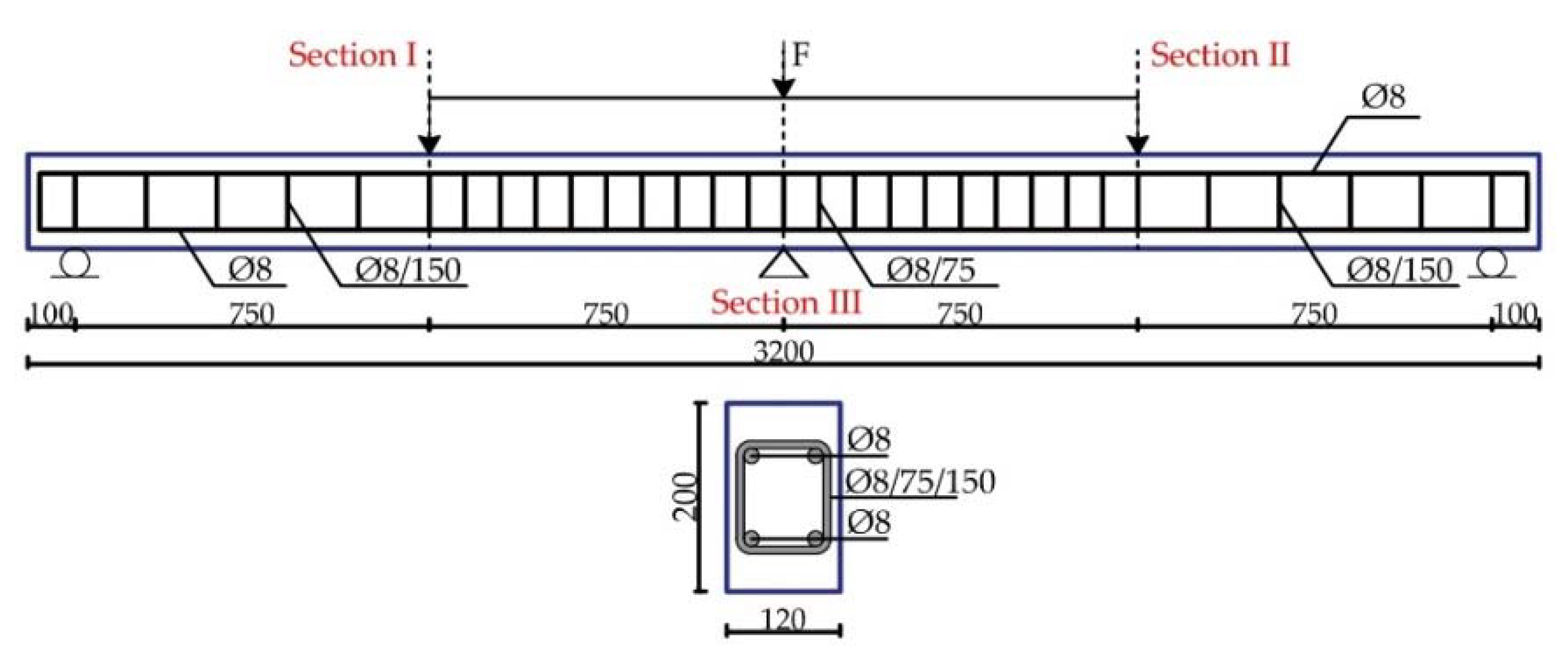
2.1. Test Specimens

Six continuous beams were made of SCC concrete with natural aggregate in accordance with the program of experimental testing in which the geometrical characteristics of the test specimens, the method of their production, arrangement and type of measuring instruments, as well as the test procedure had been defined. The dimensioning of the continuous beams was carried out in accordance with the Eurocode (EC) 2 regulation [26]. The beams have the same percentage of the longitudinal and the transverse reinforcement shown in Figure 1. The tested beams have a rectangular cross-section, having dimensions b/h = 120/200 mm, of a total length of 3200 mm, beam span 1500 mm, and reinforced with B500B reinforcement of a C30/37 designed class of SCC concrete [26].

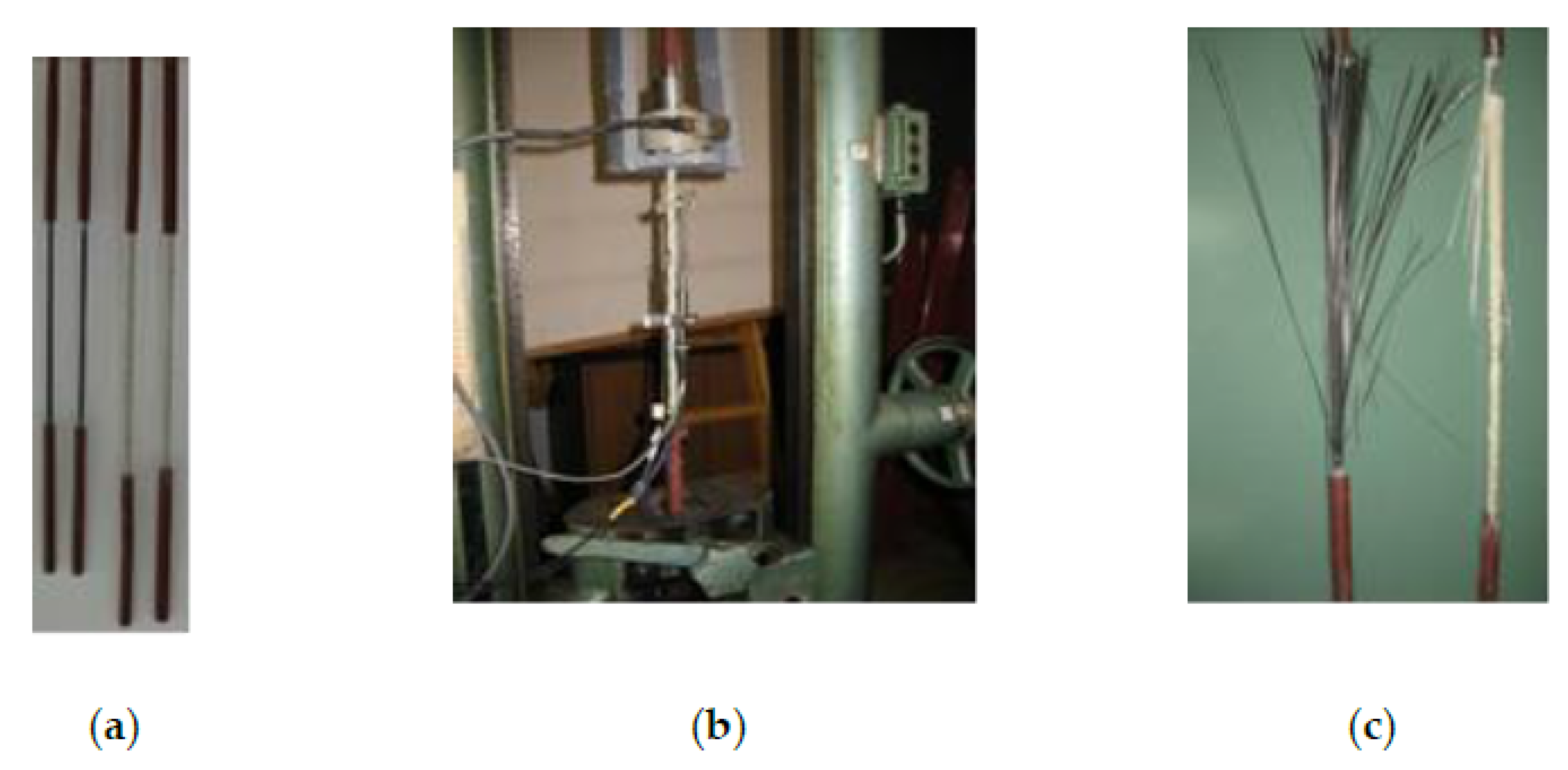
2.2. Mechanical Properties of Materials

2.2.1. Mechanical Properties of SCC Concrete

Concrete mixtures tested within the experimental research were made using CEM I 42.5 R cement, whose characteristics are presented in Table 1.
The rock flour which was used in the experiment as fine aggregate was obtained by grounding of the limestone having specific mass 2.692 g/cm3 and standard deviation of cavity share according to Rigden of 25.4% (suppliers data). For making of concrete mixtures, the particle size distribution was performed based on SRPS U. M1.057:1984, which defines the standard particle size distribution curves, A–D. The particle size distribution of the aggregate used for making SCC is presented in Figure 2.
The composition of designed concrete mixture is presented in Table 2. The additive MC Power Flow 1102 was used in the experiment. This is a super-plasticizer, a modified polycarboxylate with density of 1.06 kg/dm3. Additive dosage was 0.5% in relation to the mass of powdery components (cement and rock flour).
The experimental examination of the characteristics of SCC was carried out in two phases: (1) examination of the characteristics of the fresh concrete mass, (2) examination of the mechanical characteristics of hardened SCC.
One of the primary methods used for testing self-compacting concrete in the fresh state is the Slump-flow test (Figure 3a), which tests the consistency of fresh concrete and checks one of the key properties of SCC: workability, i.e., fluidity. The results obtained by testing fresh concrete are shown in Table 3. Based on the recommendations defined in the European Federation of National Associations Representing for Concrete (EFNARC) [27] and EN 206-9:2010 [28], the designed mixture is classified as SF1. On the basis of the measured slump time of the designed mix, it is concluded that it belongs to class VS2.
To determine the characteristic of the hardened concrete twelve 150 mm cubes and nine 150 mm diameter cylinders of 300 mm length were cast simultaneously with the beams (Figure 3b). The following tests were performed on hardened concrete: compressive strength (Figure 4a), tensile splitting strength (Figure 4b) and the determination of the tangent and secant modulus of elasticity (Figure 4c).
Determination of compressive strength of concrete was carried out on cubes having sides of 150 mm, after 2, 7, 14 and 28 days in accordance with EN 206-1. The tensile splitting strength of concrete was tested on cylinders measuring Ø150/300 mm, and it was determined after 28 days, in accordance with EN 12390-6. The determination of the tangent and secant modulus of elasticity was performed in accordance with the standard EC 2 [26]. The obtained results are provided in Table 4.

2.2.2. Mechanical Properties of Steel, FRP Reinforcement and Epoxy Adhesive

Steel reinforcement was not tested, instead the characteristics provided by the manufacturer were adopted, while for FRP reinforcement, the characteristics obtained by testing in the Laboratory of the Faculty of Mechanical Engineering at University of Nis (Figure 5) were adopted [29]. The testing was performed according to the recommendations of the American Concrete Institute (ACI) [30]. Mechanical properties of steel and FRP reinforcement are shown in Table 5.
Fiber volume fraction in CFRP bar is 71%, while fiber volume fraction in CFRP tape is 63.3% (suppliers’ data).
Mechanical properties of used epoxy adhesive are shown in Table 6.

2.3. Methods of Strengthening of RC Beams

2.3.1. NSM Strengthening Method

Strengthening of RC beams using NSM method was performed in the following way:
  • A groove is formed with the help of a saw with a diamond blade according to the dimensions depending on the diameter of the bar. Based on recommendations in the literature [31], the groove dimensions were two and a half times larger than the diameter of the mounted bars. Thus, in the case of GFRP bars (Ø10) the groove measured 25 × 25 mm, while in the case of CFRP bars (Ø8) it was 20 × 20.
  • Two-component epoxy adhesive is applied to half the depth of the groove, after which a glass or carbon FRP bar is mounted.
  • Finally, the epoxy adhesive fills the rest of the groove, whereby the surface of the concrete beam remains visually identical to the surface of the unstrengthened beam.

2.3.2. EB Strengthening Method

Strengthening of RC beam by EB method was performed in line with the manufacturer’s recommendations as follows:
  • Firstly, the tapes, having the factory size of 50×1.2 mm, were tailored to the required width of 38 mm for the purpose of achieving the identical axial stiffness as the CFRP bar, having diameter of Ø8 mm.
  • The surfaces of the beam were sound and without irregularities so there was no need for additional processing before installing the FRP tapes.
  • The surfaces of the beam were cleaned to remove dust, after which the surfaces were impregnated with primer.
  • FRP tape was also cleaned with appropriate cleaner. The solvent was evaporated and the surface of the tapes was completely dry before the application of the adhesive.
  • Two-component epoxy adhesive is applied in a thickness of approximately 1 mm on both the FRP tape and the surface of the RC beam.
  • The roller expels air bubbles and removes excess epoxy adhesive on both sides of the FRP tapes.

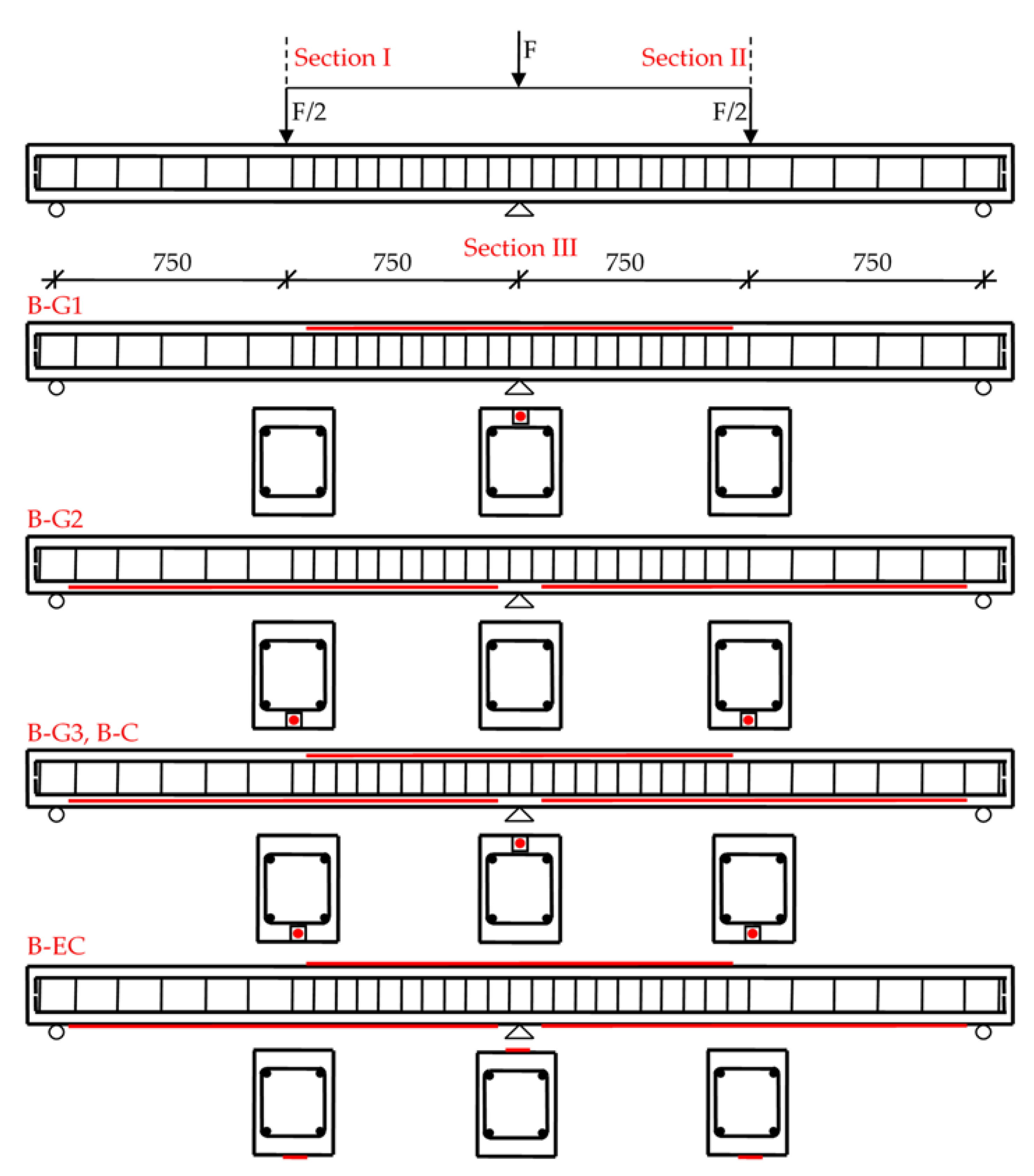
2.3.3. Variants of Strengthening of Tested Beams

Strengthening of RC beams was performed on a total of five beams, whereby position, type and method of FRP reinforcement mounting was varied (Figure 6).
The labels of the tested RC continuous beams are:
  • B-Con—Beam Control: Control (unstrengthened) beam;
  • B-G1—Beam Glass 1: Beam strengthened with GFRP bar in the negative moment zone over the middle support (hogging zone);
  • B-G2—Beam Glass 2: Beam strengthened with GFRP bar in the positive moment zones (sagging zones);
  • B-G3—Beam Glass 3: Beam strengthened with GFRP bar in the negative moment zone above the middle support and with two GFRP reinforcement bars in the positive moment zones;
  • B-C—Beam Carbon: Beam strengthened with one CFRP reinforcement bar in the negative moment zone and with two CFRP reinforcement bars in the positive moment zones;
  • B-EC—Beam External Carbon: Beam strengthened with one CFRP tape in the negative moment zone and with two CFRP tapes in the positive moment zones.

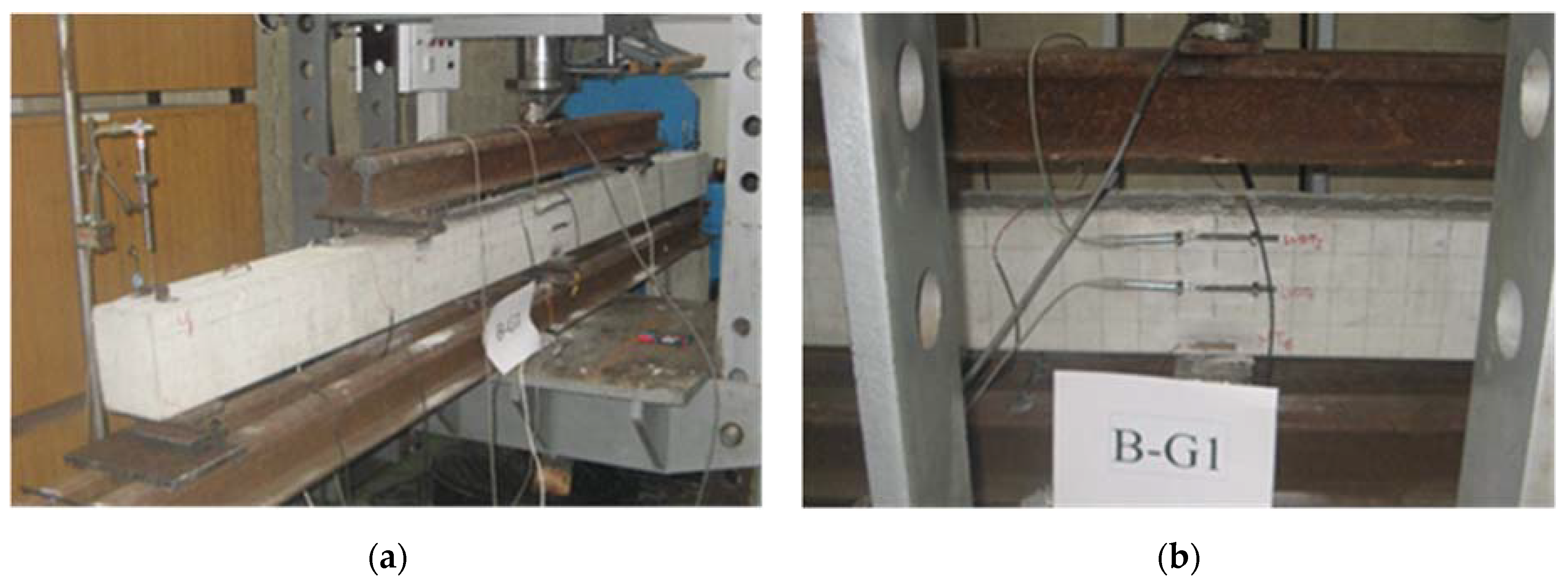
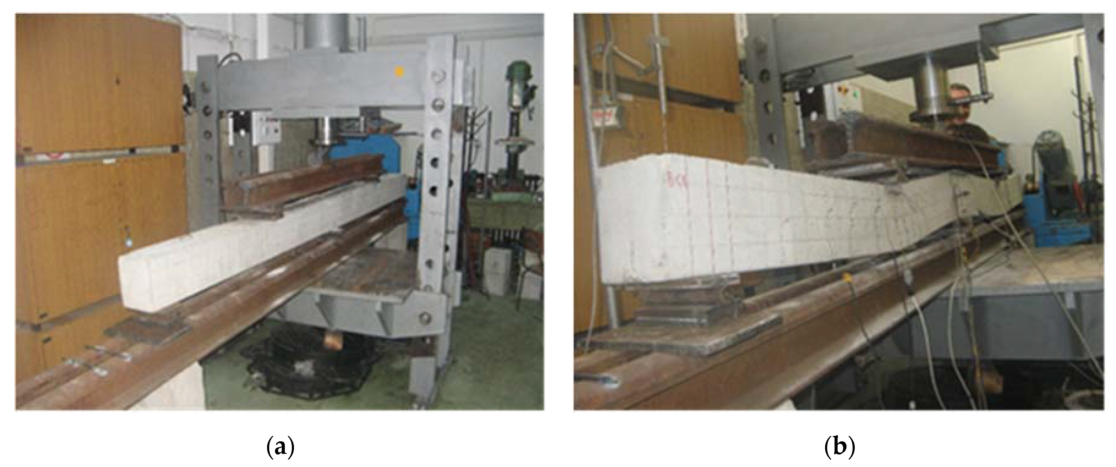
2.4. Experiment Setup and the Procedure of Load Application

Testing of continuous RC beams was performed in the Mechatronics laboratory of the Faculty of Mechanical Engineering of the University of Nis. The used measuring equipment and assisting personnel are from the Laboratory for Structural testing of the Faculty of Civil Engineering and Architecture of the University of Nis.
The load was applied to the beam in the form of two concentrated forces, which act in the middle of both spans at an axial distance of 1500 mm (Figure 1). The load transfer was realized via steel plates 100 mm wide and steel rollers Ø30 mm placed between them. The support of the beam girder is also realized via steel contact plates 100 mm wide with simulation of one fixed and two movable bearings.
The load was applied with a deflection increase rate of 0.02 mm/s (1.2 mm/min).
During the test, the following data were recorded:
  • Vertical displacements—deflections,
  • Normal strain in concrete, steel and FRP reinforcement,
To monitor the displacement, the following were used: LVDT (Linear Variable Displacement Transducers) W50, which measured deflections, and LVDT W20, as a measuring element of a dilatometer designed for measuring strains in a tensioned zone of concrete (Figure 7).
Measurement of strains in steel and FRP reinforcement, as well as on the top compressed surface of concrete, was performed with strain gauges—SG. Strain gauges with an electrical resistance of 120 Ω were used, with a base length of 6 mm on steel and FRP reinforcement, and 50 mm on concrete (Figure 8). The gluing of the measuring tapes was done with a special glue, whereby the strain gauges mounted on the steel and FRP reinforcement were additionally protected, since they were installed in concrete or epoxy glue. The position of strain gauges tapes and LVDT dilatometer in Sections I, II and II is presented in Table 7.
An electronic dynamometer (HBM U2A) was used for measuring force (load), of a measuring range up to 100 kN, accuracy 0.5%.
For recording signals and converting mechanical parameters into electrical ones, multi-channel measuring-acquisition systems MGC-plus and SPIDER 8 were used.
The converters used are connected via computer acquisition systems to calibrate instruments, read and record data. Electronic instruments were read automatically each second (quasi-dynamic), while recording and processing of data was performed via the CATMAN software package.

3. Results and Discussion

The values of the measured quantities (displacements and local deformations), due to the effect of static load, were read quasi-dynamically (every second), and then the obtained values were processed in Excel and Catman. The output results are presented in the form of diagrams, from which it is possible to most clearly observe the measured parameters (deflections and strains) as a function of the applied load.

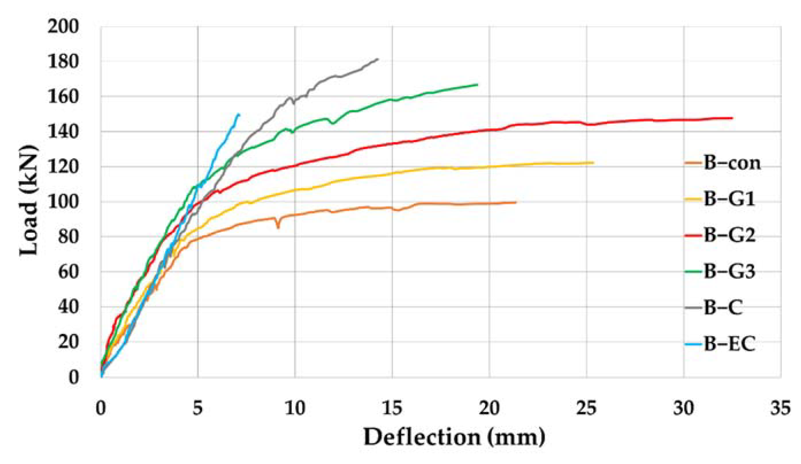
3.1. Analysis of Recorded Deflections

Special attention in this research is paid to the analysis of deflections of continuous beams. The disposition of the control beam, before and after deformation, is shown in Figure 9.
A comparative analysis of the deflection of reinforced beams was performed in relation to the control, unreinforced beam and the dependence curves between the load, and the deflection of the section in the middle of the span are shown in Figure 10.
On the curves, in general, characteristic zones can be observed when applying the load, and these are:
  • Zone before emergence of the cracks, where the relation between the load and displacement is linear,
  • Zone after emergence of the cracks, and before the yield of steel, crushing of concrete or debonding of the strengthening system, where the relationship between the load and displacement is non-linear; and
  • Zone after the yield of steel, crushing of concrete or debonding of the strengthening system until the cross-section failure.
The behavior of the tested beams until the emergence of the first cracks is almost identical, after which the strengthened beams exhibit higher rigidity and higher load-bearing capacity. With the B-EC beam, the dependence curve is generally linear even after the appearance of cracks, which indicates a small deformability but also the higher ductility of this beam.
Figure 11a shows the comparison of the maximum load capacity of the tested beams. The load-bearing capacity of all beams was increased:
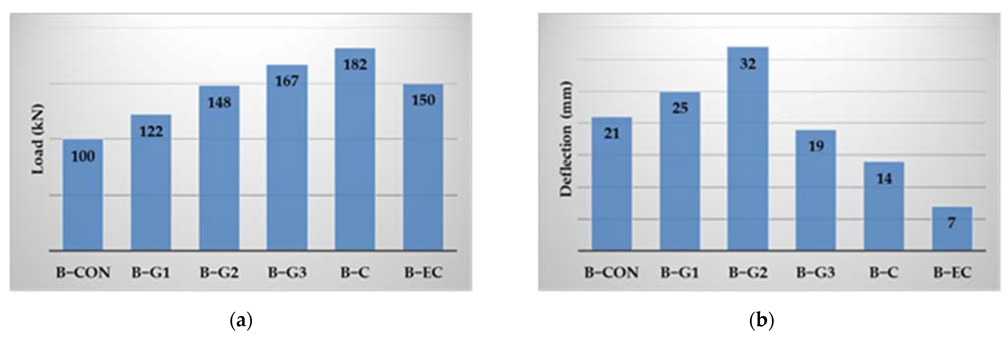
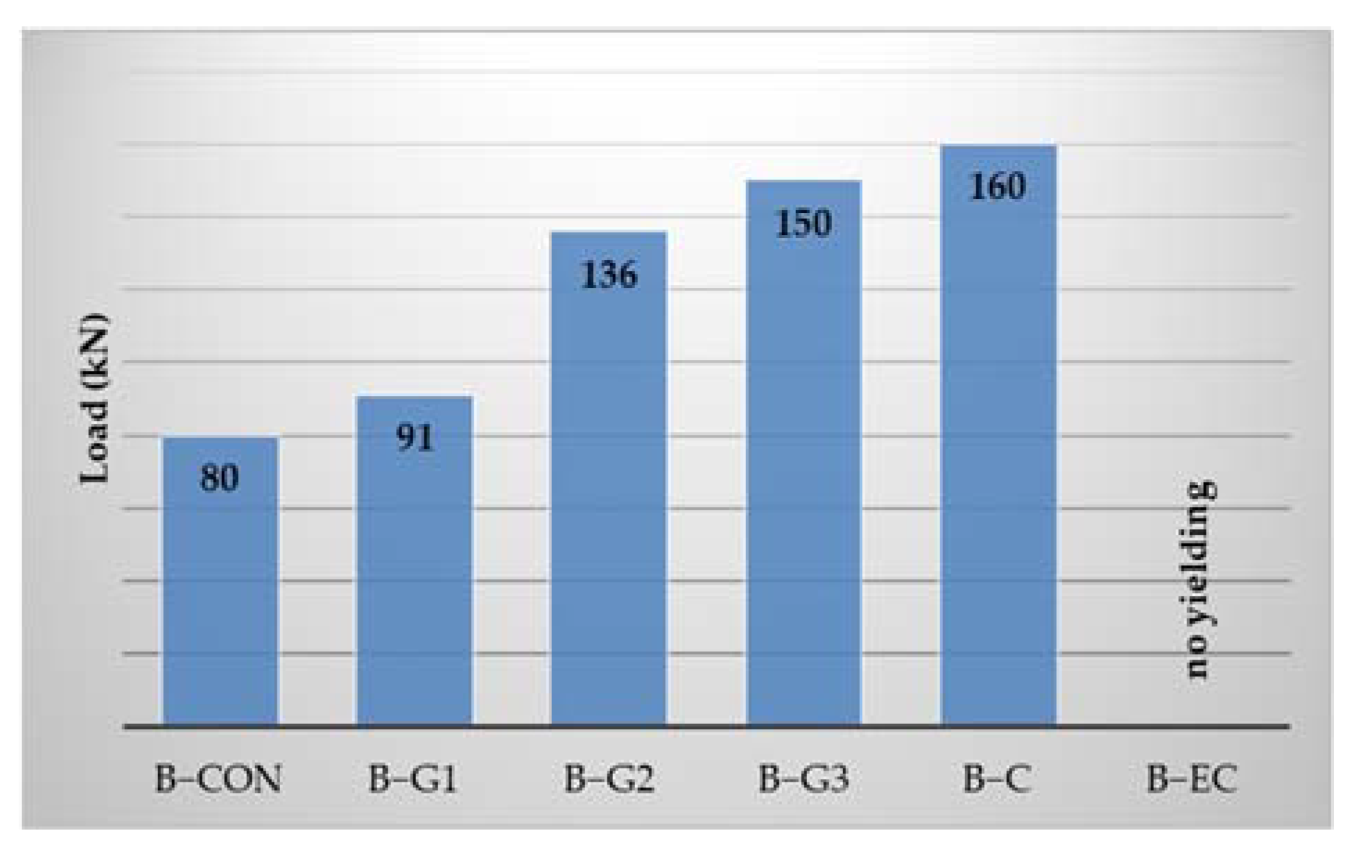
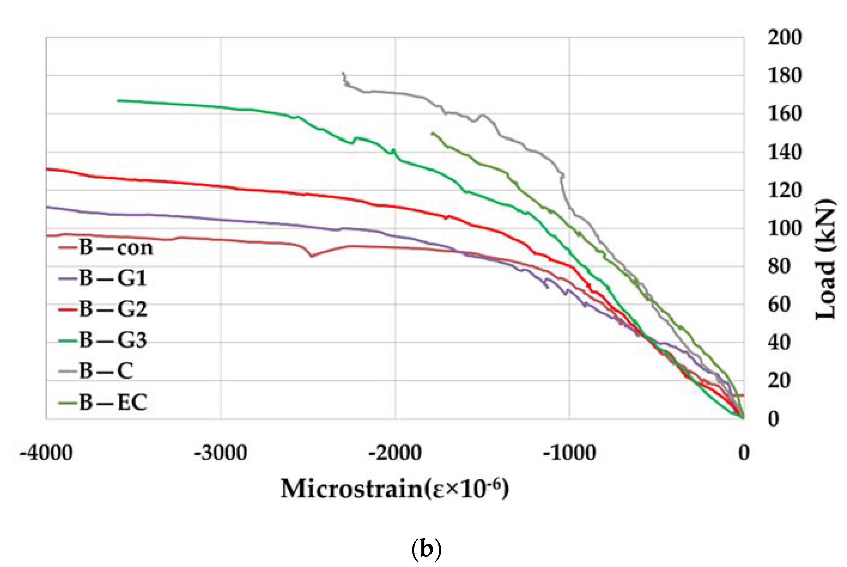
  • For beams strengthened with GFRP bars, by the NSM method, the increase in load-bearing capacity was 22–67% depending on the position of the reinforcement, with the largest increase in load-bearing capacity of beam B-G3 when the strengthening is both above the middle support and in both spans of the beam.
  • In the case when beams are strengthened with CFRP bars by the NSM method both above the middle support and in both spans of the continuous beam (B-C beam), the increase in load-bearing capacity is 82%.
  • For beams strengthened with CFRP tapes of the same axial stiffness as CFRP bars, by the EB method (B-EC beam) the increase of the load-bearing capacity compared to the B-C beam is lower, and it amounts to 50%.
Figure 11b shows maximum deflections at midspans at the moment of failure of the tested beams. It can be noticed that the maximum deflections of beams B-G1 and B-G2 increase with the increasing failure force, while in other strengthened beams the deformability is lower, which is shown by one of the most important parameters—the ductility index. The ductility index in beams strengthened with GFRP reinforcement (B-G1, B-G2 and B-G3) has satisfactory values (ID = 4 ÷ 5), while in beams strengthened with CFRP reinforcement the ductility is very small (ID = 1.5). The beam strengthened with CFRP tapes (B-EC) did not show any ductility, and the maximum deflection of this beam is the lowest compared to other beams.

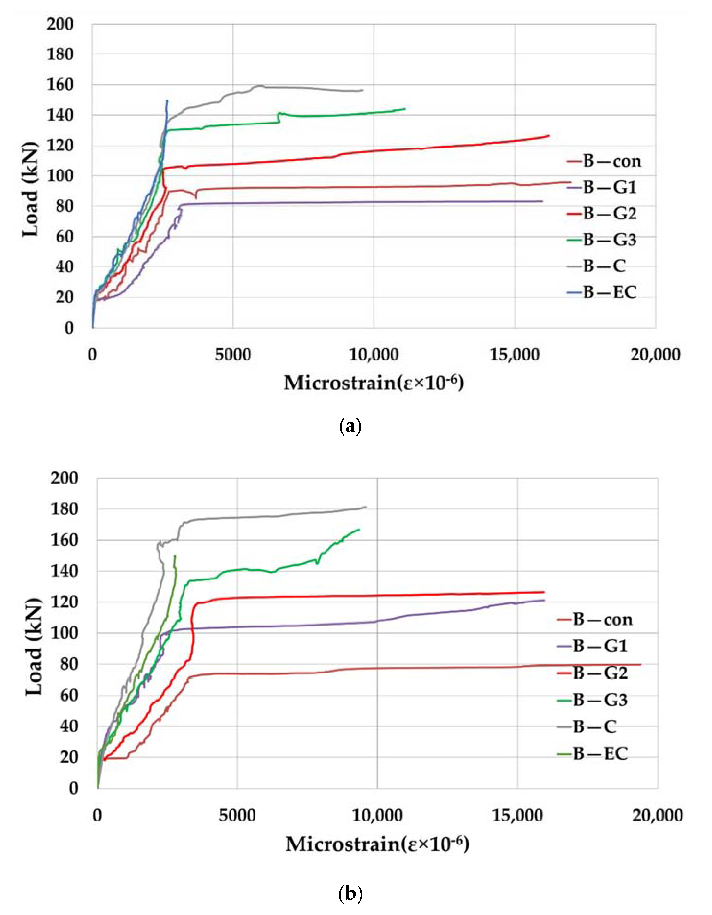
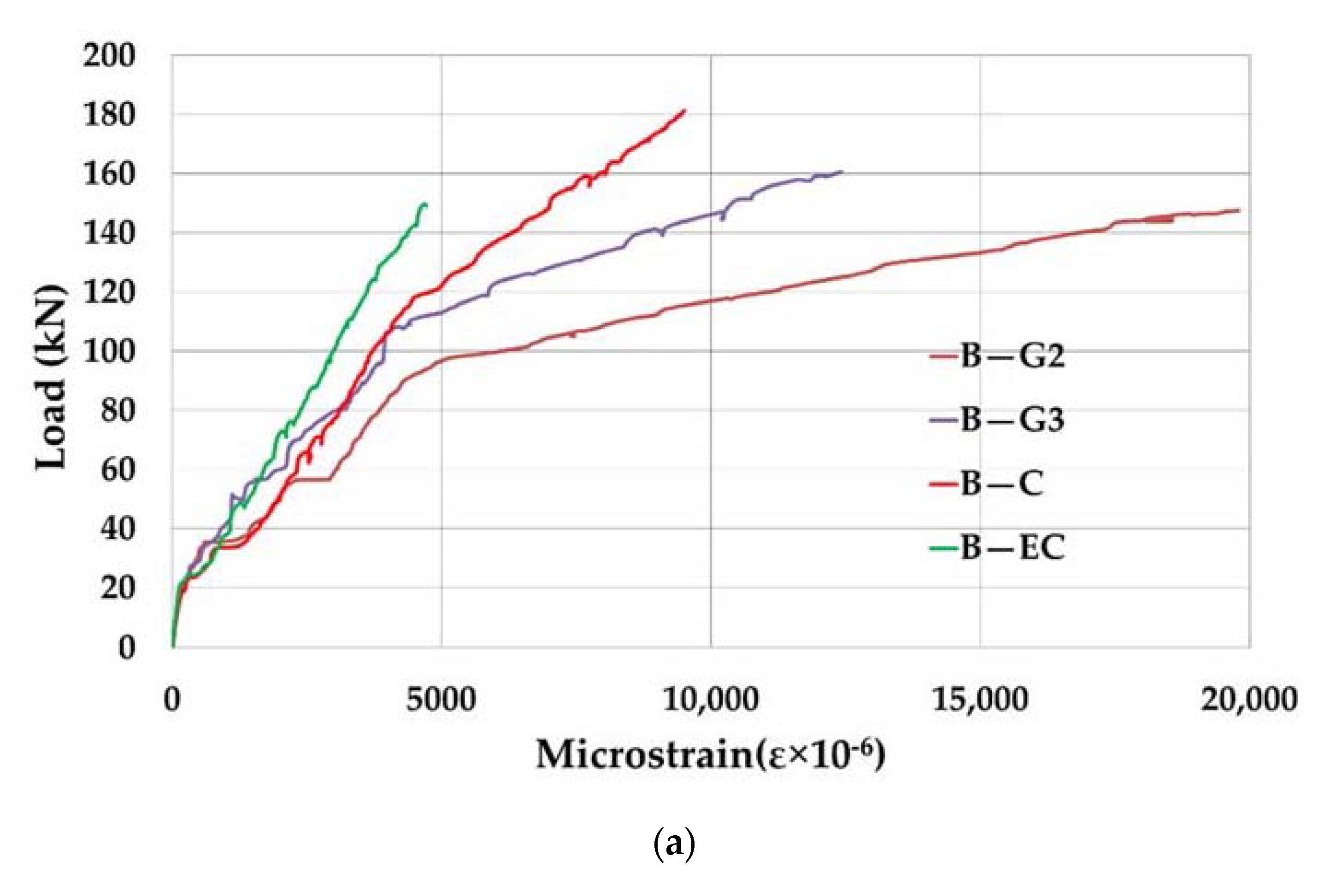
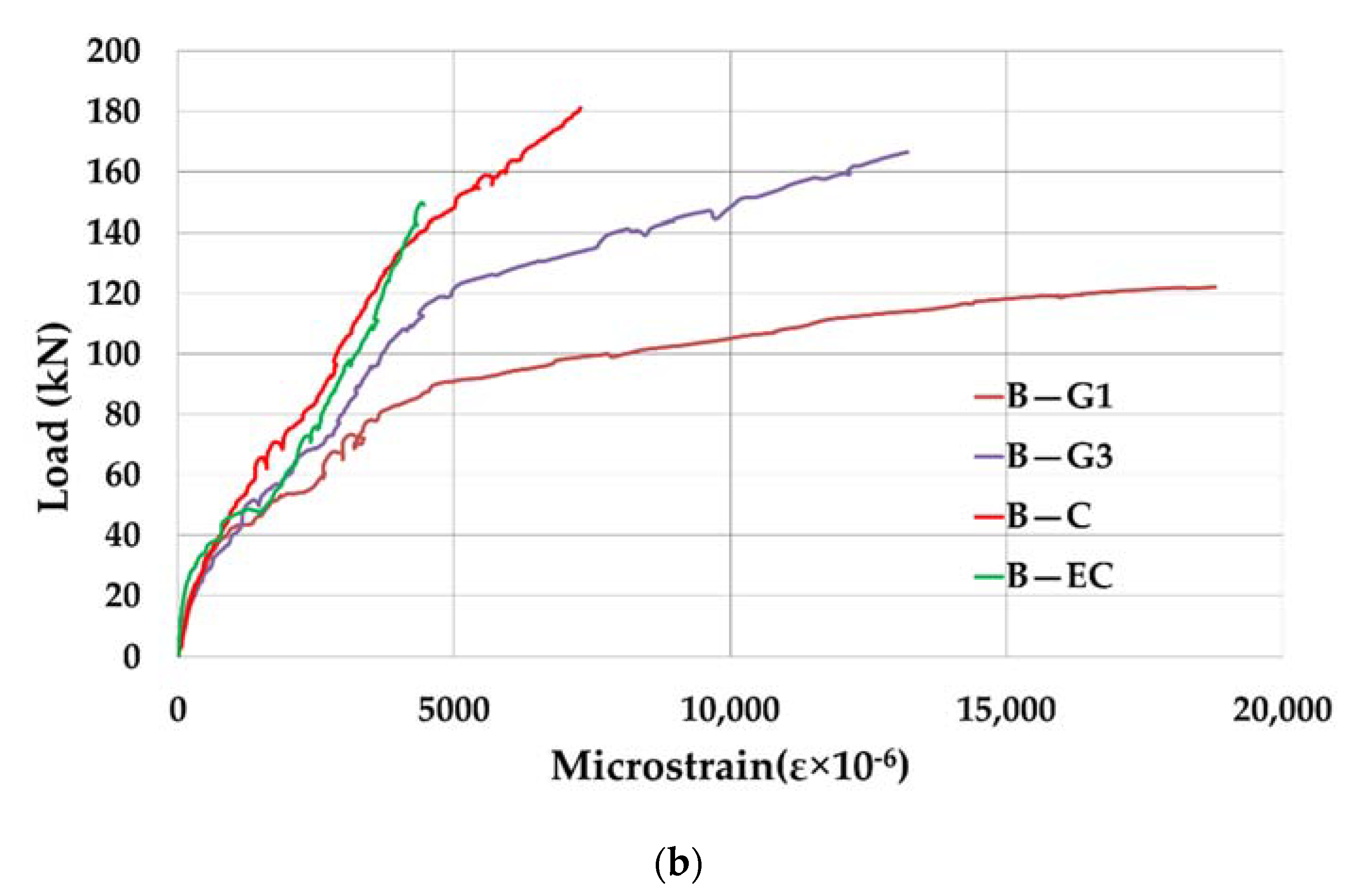
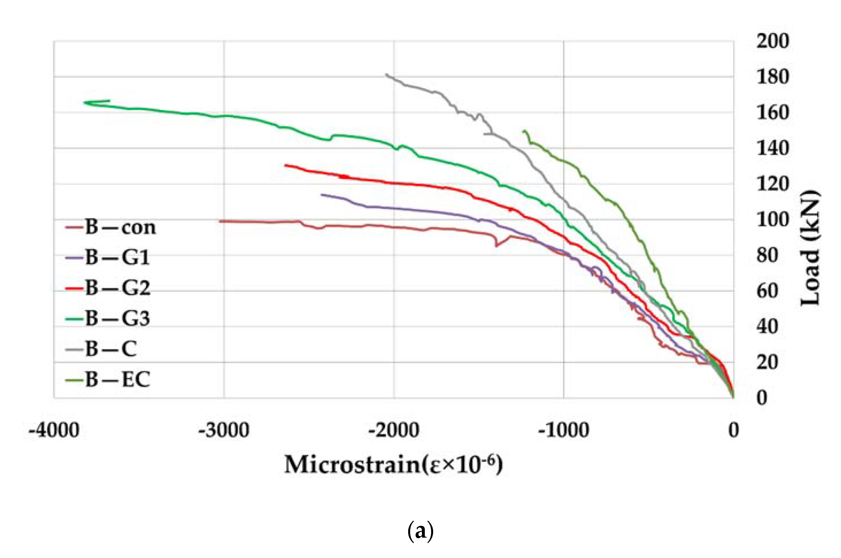
3.2. Analysis of Normal Strain in the Steel Reinforcement

Load-strain dependence diagrams in the tensioned steel reinforcement of the tested beams are presented in Figure 12a (mid-span cross-section) and Figure 12b (cross-section above the support).
It can be seen from the diagram that the strains in the tensioned steel reinforcement are negligibly small until the emergence of cracks in the concrete, after which they increase nonlinearly until the yield point in the steel reinforcement. The last phase from the yield of steel reinforcement to failure has an even more pronounced nonlinearity. There is a noticeable increase of the load at which the yield of steel reinforcement occurs in reinforced beams in relation to the control beam at which the load is Fy ≈ 80 kN.
In the case of beams reinforced with GFRP reinforcement, the increase in load at which the reinforcement steel yields is 14% for beam B-G1, 70% for beam B-G2 and 86% for beam B-G3.
In the case of the beam reinforced with CFRP bars by the NSM method, an increase in the load of 100% at which the steel reinforcement yields was achieved in relation to the control unreinforced beam.
In the case of beams reinforced with CFRP tapes by the EB method, the yield of tensioned steel reinforcement was not observed.
Figure 13 shows the comparison of the yielding load of the tested beams.

3.3. Analysis of Normal Strains in the FRP Reinforcement

Load-strain dependence diagrams in the FRP reinforcement for the tested beams are presented in Figure 14a (mid-span cross-section) and Figure 14b (cross-section above the support).
When comparing the maximum measured strains in the FRP reinforcement with the ultimate strains of GFRP and CFRP reinforcement during tensioning, it was observed that the GFRP reinforcement is maximally utilized in beams B-G1 and B-G2. For other beams, the utilization of additional FRP reinforcement is not full and it is the lowest in the case of CFRP tape reinforcement when the utilization is approximately 40%.

3.4. Analysis of Normal Strains in the Concrete

Load-strain dependence diagrams in concrete for the tested beams are presented in Figure 15a (mid-span cross-section) and Figure 15b (cross-section above the support).
From the presented diagrams, it can be observed that the strains in concrete are compatible to those in tensioned steel reinforcement, until the onset of first cracks in concrete. After that, the strains are nonlinear, whereby that nonlinearity is more pronounced after the yield of steel reinforcement.

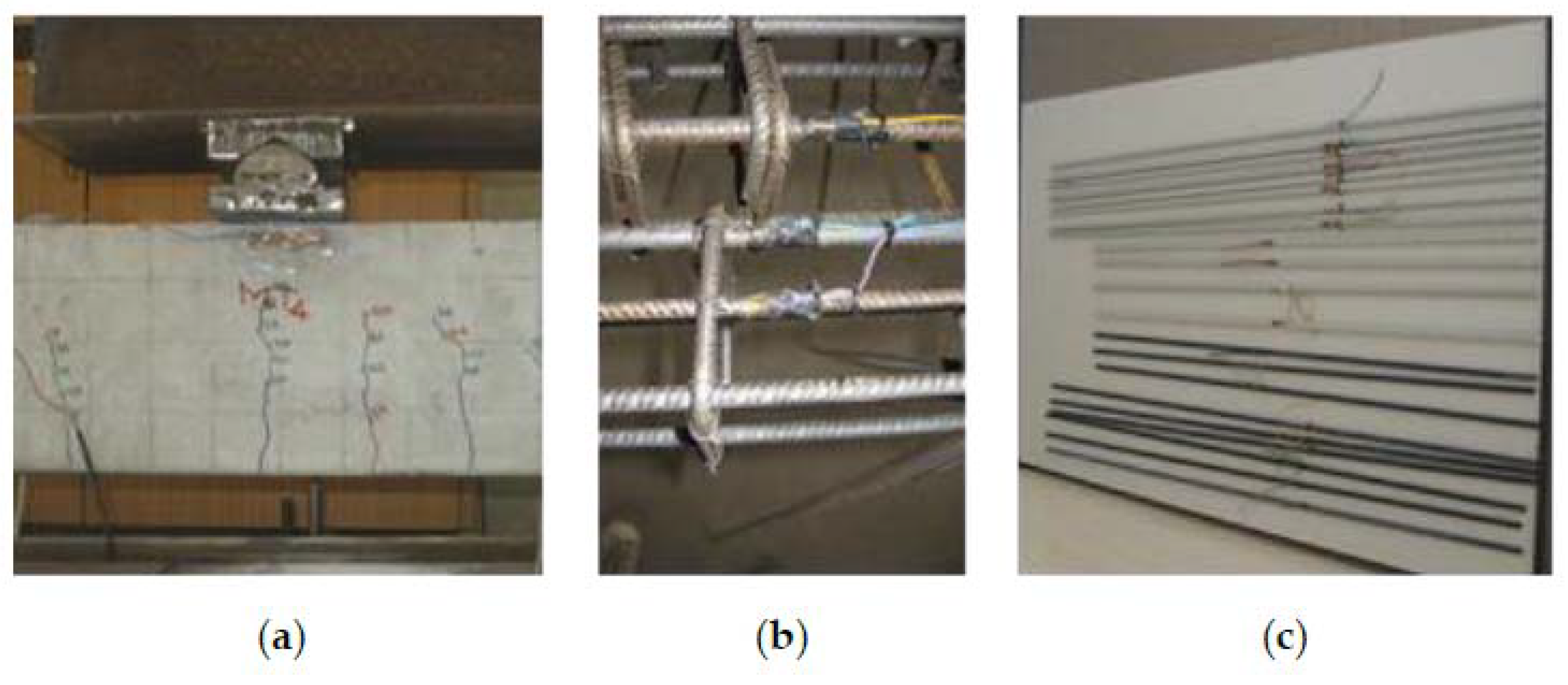
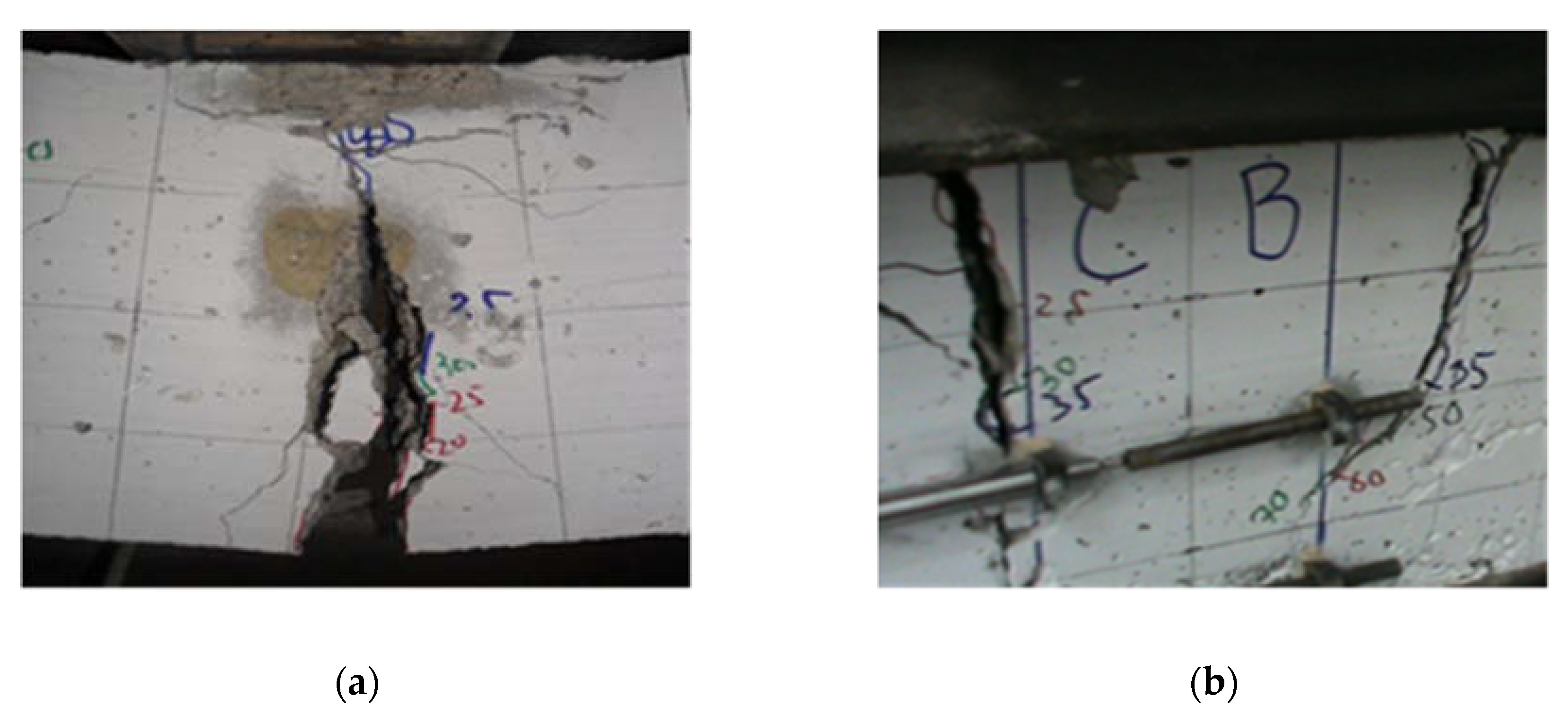
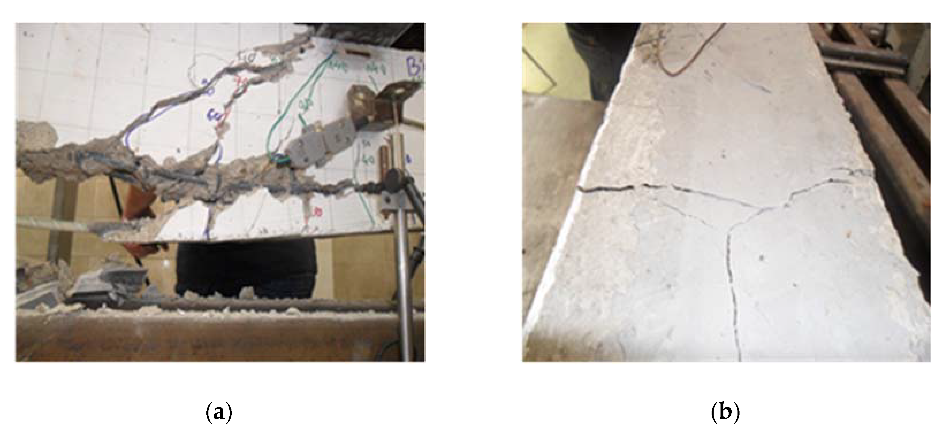
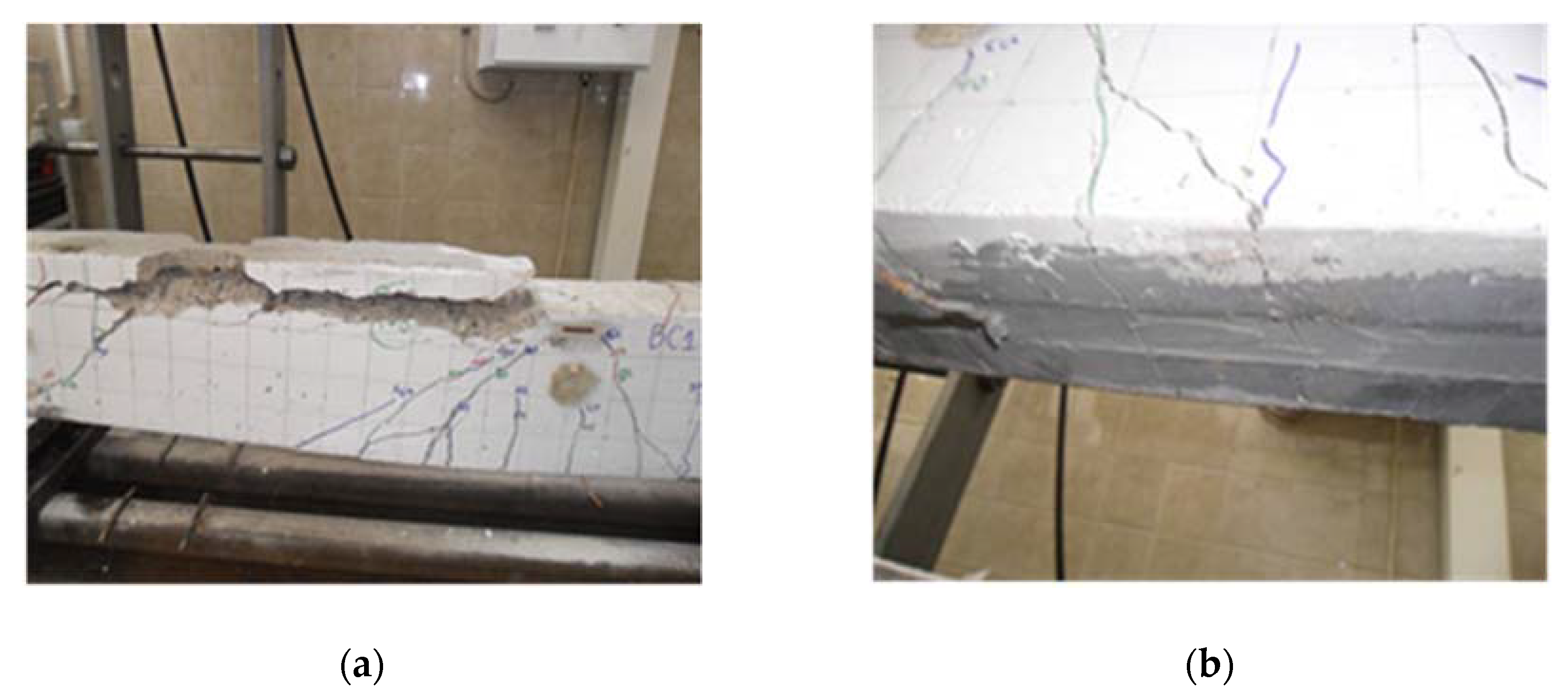
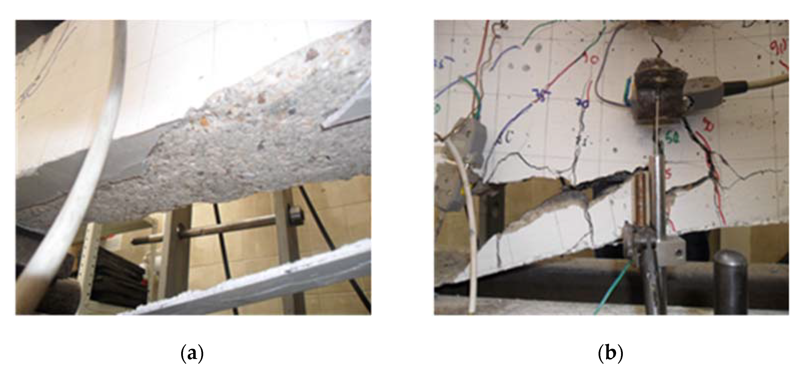
3.5. Beam Failure Modes

Figure 16 shows the failure mode of the control beam. The failure of the beam is caused by the formation of a plastic hinge, i.e., by reaching the ultimate strain of steel reinforcement during tensioning, first in the cross-section above the middle support. By reaching the ultimate strain of the steel reinforcement during tension in the cross section in the span a plastic hinge is formed and thus the failure mechanism of the beam. The maximum realized force was 100 kN, after which the deformations increase without increasing the force.
In the case of the beam girder B-G1, which is reinforced with a GFRP bar above the middle support, the cross section in the span fails first, reaching the ultimate strain of the steel reinforcement, which is followed by concrete crushing (Figure 17)—by forming a plastic joint in that cross section. The formation of the failure mechanism occurs due to crushing of concrete in the cross-section over the middle support, without debonding of the FRP reinforcement system, which indicates the complete utilization of this system. The load-bearing capacity of this beam is 122 kN, and exceptional deformability and failure without major damage to the beam were observed.
In Figure 18 the shape of the failure of the beam strengthened with GFRP reinforcement in the zone of positive moments (bottom side of the beam)—beam B-G2—is shown. A failure of the section above the middle support was first observed due to reaching the limit strain of the steel reinforcement during tensioning (Figure 18a). The formation of the failure mechanism occurs due to the failure of the cross section in the span, caused by separation of the concrete at the level of the longitudinal steel reinforcement (Figure 18b). Crushing of concrete was observed in the zone of force application (Figure 18b). Transverse cracks in the concrete on the bottom side of the beam intersect the slot with the epoxy filling. The load bearing capacity of this beam is 148 kN, the deformability is good and the failure occurs with damage to the beam (Figure 18b).
Beam fracture B-G3 is caused by debonding of epoxy and concrete, as a result of which concrete separates at the level of the protective layer (Figure 19a). The load-bearing capacity of this beam is high (Fu = 167 kN), but the failure is sudden with a loud crack and with a considerable damage to the beam. Crushing of concrete was observed in the zone of force application as well as transverse cracks in concrete both on the bottom and on the top side of the beams intersecting the groove with the epoxy infill (Figure 19b). Deformability is lower compared to other beams in which strengthening was accomplished using GFRP reinforcement.
Figure 20 show the failure shape of a beam strengthened with CFRP reinforcement in the zone of negative moments above the middle support (top side of the beam) and in the zone of positive moments (bottom side of the beam) caused by incremental application of test load until failure. It is observed that the failure occurs by debonding of epoxy and concrete, as a result of which concrete separates at the level of the protective layer (Figure 20a). The load-bearing capacity of this beam is the highest (Fu = 182 kN) in comparison with other tested beams, but the deformability is extremely low, so that failure occurs suddenly with considerable damage to the beam.
Failure of beams reinforced by the EB method with CFRP tapes (B-EC beams) occurs much earlier than in beams strengthened with CFRP bars by the NSM method (B-C beams). In general, the behavior of these beams is similar until the onset of tape separation in B-EC beams. Failure (fracture) occurs due to the sudden separation of the tape due to the loss of bond at the joint of concrete and epoxy adhesive (Figure 21a), after which the protective layer of concrete separates (Figure 21b). Failure due to the debonding of the reinforcement system is the most common failure of beams strengthened by the EB method, and it is also the most prominent deficiency of this method. Debonding failure prevention can be achieved by various anchoring systems such as: anchor spikes, U-Anchors, transverse wrapping, plate anchors, bolted angles and other miscellaneous systems [32]. The fracture load was 150 kN (at B-C beam 180 kN) where the deformability of this beam is very low with a very linear relationship between the load and the deflection of the beam.

4. Conclusions

Composite materials are certainly materials of the future but also of the present. Application of the fiber polymer materials provides great opportunities in repair and strengthening of the RC structures, thus extending their service life [33].
Experimental testing of six two-span continuous beams made of self-compacting concrete strengthened with fiber reinforced polymer (FRP) materials was done in this research. The influence of the method of strengthening, type of the FRP material and position of the strengthening on the flexural behavior of the examined beams were analyzed. Based on all of the above, general conclusions can be summarized:
  • The use of FRP materials in strengthening of RC continuous beams, even with a small amount of additional reinforcement, can considerably increase their load-bearing capacity. An increase of 22–82% in the load-bearing capacity of the strengthened beams compared to the control beam was achieved.
  • The highest increase of the load-bearing capacity was in the beams strengthened both in the negative moment zone above the middle support and in the positive moment zones in the spans, and it ranges within 50–82% depending on the type of FRP reinforcement (glass and carbon) and the method of strengthening (EB and NSM).
  • Strengthening with CFRP materials results in a higher failure load, but the price of these materials is considerably higher compared to GFRP materials so in each individual case, it should be assessed which material is more adequate.
  • The use of FRP materials also influenced the increase of the yielding load which was in the range from 14% to 100% compared to the yielding load of the control beam.
  • With the increase in the amount of FRP reinforcement, it is noticeable that there is a decrease in the deformability or ductility of reinforced beams, which is one of the main disadvantages of using FRP reinforcement.
  • The failure modes of the strengthened beam with higher percentage of FRP reinforcement were brittle with separation of the concrete protective layer and before fully utilizing the tensile strength of the FRP material. The lowest efficiency was observed in the beam strengthened by the EB method due to the separation of the tapes.
  • Debonding of the FRP system in the beams strengthened in the same manner occurred earlier with the EB method, so the efficiency and utilization of the tensile strength of the FRP reinforcement is higher with the NSM method.
  • The basic disadvantages of the NSM method compared to the EB method are the groove size for installing the FRP bars and the higher price, which lead to the conclusion that the assessment of which method is more adequate should be made on a case by case basis.
In further experimental research, the use of narrow strips instead of bars in the NSM method, given the smaller size of the required gap in the concrete, can be analyzed. Further, the numerical model of the examined continuous beams using the finite element method should be made, validated and verified with experimentally obtained results.

Author Contributions

Conceptualization, Ž.P. and B.M. (Bojan Milošević); methodology, Ž.P. and B.M. (Biljana Mladenović); software, A.Z. and P.P.; validation, S.R. and B.M. (Bojan Milošević); formal analysis, B.M. (Bojan Milošević); investigation, P.P., S.R. and D.Z.; resources, S.R. and B.M. (Bojan Milošević); data curation, A.Z.; writing—original draft preparation, Ž.P. and B.M.; writing—review and editing, S.R. and D.Z.; visualization, B.M. (Biljana Mladenović); supervision, B.M. (Biljana Mladenović) and D.Z.; project administration, Ž.P. All authors have read and agreed to the published version of the manuscript.

Funding

This research received no external funding.

Institutional Review Board Statement

Not applicable.

Informed Consent Statement

Not applicable.

Conflicts of Interest

The authors declare no conflict of interest.

References

  1. Bilotta, A.; Ceroni, F.; di Ludovico, M.; Nigro, E.; Pecce, M.; Manfredi, G. Bond efficiency of EBR and NSM systems for strengthening concrete members. J. Compos. Constr. 2011, 15, 757–772. [Google Scholar] [CrossRef]
  2. ISIS Educational Module 2. An Introduction to FRP Composites for Construction; A Canadian Network of Centres of Excellence: Ottawa, ON, Canada, 2006. [Google Scholar]
  3. Fib, Bulletin.14 (Task Group 9.3). Externally Bonded FRP Reinforcement for RC Structures. Technical Report on the Design and Use of Externally Bonded Fiber Reinforced Polymer Reinforcement (FRP EBR) for Reinforced Concrete Structures; International Federation for Structural Concrete: Lausanne, Switzerland, 2001. [Google Scholar]
  4. Sakr, M.A.; Khalifa, T.M.; Mansour, W.N. External Strengthening of RC Continuous Beams Using FRP Plates: Finite Element Model. In Proceedings of the Second International Conference on Advances in Civil, Structural and Mechanical Engineering—CSM 2014, Birmingham, UK, 1–2 June 2014. [Google Scholar] [CrossRef]
  5. Akbarzadeh, H.; Maghsoudi, A.A. Experimental and analytical investigation of reinforced high strength concrete continuous beams strengthened with fiber reinforced polymer. Mater. Des. 2010, 31, 1130–1147. [Google Scholar] [CrossRef]
  6. Aiello, M.A.; Valente, L.; Rizzo, A. Moment redistribution in continuous reinforced concrete beams strengthened with carbon fiber- reinforced polymer laminates. Mech. Compos. Mater. 2007, 43, 453–466. [Google Scholar] [CrossRef]
  7. Maghsoudi, A.A.; Bengar, H.A. Moment redistribution and ductility of RHSC continuous beams strengthened with CFRP. Turk. J. Eng. Environ. Sci. 2009, 33, 45–59. [Google Scholar]
  8. Rahman, M.M.; Jumaat, M.Z. The Effect of CFRP Laminate Length for Strengthening the Tension Zone of the Reinforced Concrete T-Beam. J. Sci. Res. Rep. 2013, 2, 626–640. [Google Scholar] [CrossRef]
  9. Al-Khafaji, A.; Salim, H. Flexural Strengthening of RC Continuous T-Beams Using CFRP. Fibers 2020, 8, 41. [Google Scholar] [CrossRef]
  10. Soumya, S. Strengthening of RC Continuous Beam Using FRP Sheet; Department of Civil Engineering, National Institute of Technology Rourkela: Odisha, India, 2012. [Google Scholar]
  11. Wang, X.; Zhou, C. Numerical investigation for the flexural strengthening of reinforced concrete beams with external prestressed HFRP sheets. Constr. Build. Mater. 2018, 804–815. [Google Scholar] [CrossRef]
  12. Wang, X.; Zhou, C.; Ai, J.; Petru, M.; Liu, Y. Numerical investigation for the fatigue performance of reinforced concrete beams strengthened with external prestressed HFRP sheet. Constr. Build. Mater. 2020, 237, 117601. [Google Scholar] [CrossRef]
  13. Zhang, C.; Wang, J. Viscoelastic analysis of FRP strengthened reinforced concrete beams. Compos. Struct. 2011, 93, 3200–3208. [Google Scholar] [CrossRef]
  14. Aidoo, J.; Harries, K.A.; Petrou, M.F. Full-scale experimental investigation of repair of reinforced concrete interstate bridge using CFRP materials. J. Bridge Eng. 2006, 11, 350–358. [Google Scholar] [CrossRef]
  15. Quattlebaum, J.B.; Harries, K.A.; Petrou, M.F. Comparison of three flexural retrofit systems under monotonic and fatigue loads. J. Bridge Eng. 2005, 10, 731–740. [Google Scholar] [CrossRef]
  16. Rosenboom, O.A.; Rizkalla, S. Fatigue behavior of prestressed concrete bridge girders strengthened with various CFRP systems. ASCE J. Compos. Constr. 2007, 230, 764–776. [Google Scholar]
  17. Okamura, H.; Ozawa, K. Mix Design for Self-Compacting Concrete, Concrete. Libr. Jpn. Soc. Civ. Eng. 1995, 25, 107–120. [Google Scholar]
  18. Persson, B. A comparison between mechanical properties of self-compacting concrete and the corresponding properties of normal concrete. Cem. Concr. Res. 2001, 31, 193–198. [Google Scholar] [CrossRef]
  19. Okamura, H.; Ouchi, M. Self-Compacting Concrete. J. Adv. Concr. Technol. 2003, 5, 5–15. [Google Scholar] [CrossRef]
  20. Domone, P.L. A review of the hardened mechanical properties of self-compacting concrete. Cem. Concr. Compos. 2007, 1–12. [Google Scholar] [CrossRef]
  21. Aslani, F.; Nejadi, S. Mechanical properties of conventional and self-compacting concrete: An analytical study. Constr. Build. Mater. 2012, 36, 330–347. [Google Scholar] [CrossRef]
  22. Vidivelli, B.; Kathiravan, T.; Gobi, T. Flexural Behaviour of Self Compacting and Self Curing Concrete Beams. Asian Rev. Civ. Eng. 2013, 2, 1–9. [Google Scholar]
  23. Shi, C.; Wu, Z.; Lv, K.; Wu, L. A review on mixture design methods for self-compacting concrete. Constr. Build. Mater. 2015, 84, 387–398. [Google Scholar] [CrossRef]
  24. Khatab, T.A.M.; Ashour, F.A.; Sheehan, T.; Lam, D. Experimental investigation on continuous reinforced SCC deep beams and Comparisons with Code provisions and models. Eng. Struct. 2017, 131, 264–274. [Google Scholar] [CrossRef]
  25. Petrović, Ž.; Milošević, B.; Zorić, A.; Ranković, S.; Mladenović, B.; Zlatkov, D. Flexural Behavior of Continuous Beams Made of Self-Compacting Concrete (SCC)—Experimental and Numerical Analysis. Appl. Sci. 2020, 10, 8654. [Google Scholar] [CrossRef]
  26. European Commitee for Standardization. Eurocode 2. Design of Concrete Structures–Part 1-1: General Rules and Rules for Buildings; European Commitee for Standardization: Brussels, Belgium, 2004. [Google Scholar]
  27. EFNARC. The European Guidelines for Self-Compacting Concrete Specification; Production and Use; EFNARC: Farham, UK, 2005; p. 66. [Google Scholar]
  28. European Commitee for Standardization. EN 206-9:2010. Additional Rules for Self-Compacting Concrete (SCC); European Commitee for Standardization: Brussels, Belgium, 2010; p. 27. [Google Scholar]
  29. Ranković, S. Experimental and Theoretical Analysis of Limit State RC Linear Plane Structures Strengthened with NSM FRP Elements. Ph.D. Thesis, University of Niš, Niš, Serbia, 2011. [Google Scholar]
  30. ACI 440.3R-04. Guide Test Methods for Fiber-Reinforced Polymers (FRPs) for Reinforcing or Strengthening Concrete Structures; ACI Committee 440; American Concrete Institute: Farmington, Hills, MI, USA, 2004; p. 16. [Google Scholar]
  31. Hassan, T.K.; Rizkalla, S.H. Bond Mechanism of Near-Surface-Mounted Fiber-Reinforced Polymer Bars for Flexural Strengthening of Concrete Structures. ACI Struct. J. 2004, 101, 830–839. [Google Scholar]
  32. Grelle, S.V.; Sneed, L.H. Review of Anchorage Systems for Externally Bonded FRP Laminates. Int. J. Cocnr. Struct. Mater. 2013, 7, 17–33. [Google Scholar] [CrossRef] [Green Version]
  33. Petrović, Ž. Experimental—Theoretical Analysis of Limit States of Continuous Beams Made of Self-Compacting Concrete Strengthened with Fiber Reinforced Polymer (FRP). Ph.D. Thesis, University of Niš, Niš, Serbia, 2016. [Google Scholar]
Figure 1. Reinforcing of the tested beams.
Applsci 11 04032 g001
Figure 2. Particle size distribution of aggregates.
Applsci 11 04032 g002
Figure 3. (a) Slump-flow test; (b) Concrete cubes and cylinders.
Applsci 11 04032 g003
Figure 4. Determination of the characteristics of hardened concrete: (a) Compressive strength; (b) Tensile strength; (c) Modulus of elasticity.
Applsci 11 04032 g004
Figure 5. Determination of the characteristics of FRP materials: (a) Test specimens; (b) Test setup; (c) Specimens after testing [29].
Applsci 11 04032 g005
Figure 6. Variants of strengthening of tested beams.
Applsci 11 04032 g006
Figure 7. (a) Deflectometer U1 (LVDT); (b) Dilatometer positions.
Applsci 11 04032 g007
Figure 8. Strain gauges on: (a) Concrete; (b) Steel; (c) FRP reinforcement.
Applsci 11 04032 g008
Figure 9. Disposition of the control beam: (a) Before loading; (b) Under loading.
Applsci 11 04032 g009
Figure 10. Mid-span deflection diagram for different strengthening variants.
Applsci 11 04032 g010
Figure 11. (a) Comparison of maximum load-bearing capacity of the tested beams; (b) Comparison of maximum deflections at half of the span of the tested beams.
Applsci 11 04032 g011
Figure 12. Load vs. microstrain curves in steel reinforcement for the section: (a) At the middle of span—Section I; (b) Above the middle support—Section III.
Applsci 11 04032 g012
Figure 13. Comparison of the yielding load of the tested beams.
Applsci 11 04032 g013
Figure 14. Load vs. microstrain curves in FRP reinforcement for the section: (a) At the middle of span—Section I; (b) Above the middle support—Section III.
Applsci 11 04032 g014aApplsci 11 04032 g014b
Figure 15. Load vs. microstrain curves for concrete for the section: (a) At the middle of span—Section I; (b) Above the middle support—Section III.
Applsci 11 04032 g015aApplsci 11 04032 g015b
Figure 16. Control beam: (a) Failure of the cross-section at mid-span of control beam; (b) Failure of the cross-section above the support of control beam.
Applsci 11 04032 g016
Figure 17. Beam B-G1: (a) Disposition of cracks and failure of the cross-section at mid-span; (b) Disposition of cracks and failure of the cross section above the support.
Applsci 11 04032 g017
Figure 18. Beam B-G2: (a) Failure of the cross section above the support; (b) Failure of cross section in the span due to concrete separation.
Applsci 11 04032 g018
Figure 19. Beam B-G3: (a) Concrete separation at the level of protective layer of concrete; (b) Cracks in concrete on the top side of the beam intersecting the groove with the epoxy infill.
Applsci 11 04032 g019
Figure 20. Beam B-C: (a) Concrete separation at the level of protective layer of concrete (b) Arrangement of cracks.
Applsci 11 04032 g020
Figure 21. Beam B-EC: (a) Debonding at the joint of concrete and epoxy adhesive on the beam bottom side; (b) Concrete separation at the level of protective layer of concrete.
Applsci 11 04032 g021
Table 1. Physical–mechanical characteristics of cement.
Characteristics of CementValue
Setting Time, MinStart 176, End 226
Density3.13 g/cm3
Bulk density in loose state930 kg/m3
Bulk density in compacted state1515 kg/m3
Tensile strength at 2 days6.98 N/mm2
Tensile strength at 28 days9.30 N/mm2
Compressive strength at 2 days31.33 N/mm2
Compressive strength at 28 days55.15 N/mm2
Table 2. Concrete composition.
Mass for 1 m3 (kg)
limestone filler100.00
cement320.00water absorption (%)
fraction 0–4 mm807.500.80
fraction 4–8 mm380.000.50
fraction 8–16 mm553.000.40
water210.00
MC Power Flow 1102 additive2.10
Table 3. The test results obtained on fresh concrete.
Density (kg/m3)Slump-Flow Test D (mm)t500 (s)ωc
(Water Cement Ratio)
23056054.80.49
Table 4. The test results obtained on hardened concrete.
Compressive Strength
(MPa)
Tensile Strength
(MPa)
Modulus of Elasticity
(GPa)
SecantTangent
fc,2fc,7fc,14fc,28fct,28EcEcm
12.0618.1524.9328.823.4425.3524.35
Standard deviation (σ)0.630.921.151.240.151.251.15
Table 5. Mechanical properties of steel and FRP reinforcement.
ReinforcementDimension
(mm)
Modulus of Elasticity
(GPa)
Ultimate Strain
(ε × 10−6)
Yield Strength
(MPa)
Tensile Strength
(MPa)
steelØ8200.0-500560
CFRP barØ8148.113,434-1940
GFRP barØ1047.015,635-735
CFRP tape50/1.2165.017,000-3100
Table 6. Mechanical properties of epoxy adhesive.
density1.70 kg/dm3
Linear shrinkage0% (at +23°)
Compressive modulus of elasticity6000 MPa
Bond strength>3 MPa
Shear strength in strengthening>35 MPa
Bond strength in strengthening>18 MPa
Table 7. Position of strain gauge tapes (SG) and linear variable displacement transducers (LVDT) dilatometers in Sections I, II and III of the tested beams.
Beam LabelTensioned Steel ReinforcementCompressed ConcreteFRPDeflection
Section IB–conSG1SG4-LVDT1
B–G1SG1SG4-LVDT1
B–G2SG1SG4SG6LVDT1
B–G3SG1SG4SG6LVDT1
B–CSG1SG4SG6LVDT1
B–ECSG1SG4SG6LVDT1
Section IIIB–conSG2D1--
B–G1SG2D1SG6-
B–G2SG2D1--
B–G3SG2D1SG7-
B–CSG2D1SG7-
B–ECSG2D1SG7-
Section IIB–conSG3SG5-LVDT2
B–G1SG3SG5-LVDT2
B–G2SG3SG5SG7LVDT2
B–G3SG3SG5SG8LVDT2
B–CSG3SG5SG8LVDT2
B–ECSG3SG5SG8LVDT2
Publisher’s Note: MDPI stays neutral with regard to jurisdictional claims in published maps and institutional affiliations.

