
Exoscarne: Assistive Strategies for an Industrial Meat Cutting System Based on Physical Human-Robot Interaction

 ,
,  , and
, and
Abstract
1. Introduction and Motivation
- Reduction of occupational risks by reducing the arduousness of the operators’ tasks and improving their working conditions.
- Overcome a major shortage of skilled labour by reducing the lack of image and attractiveness, particularly among young people (hardship in low-value jobs, etc.), which will help maintain or even develop jobs in the sector.
- Improve the competitiveness of companies by reducing the direct and indirect costs of work stoppages and by increasing productivity.
- Improve the safety of products by reducing the direct handling of products by operators or by integrating cleaning systems (e.g., sterilization of tools online between each operation).
- Compensate the weight of the cutting tool.
- Permit the user to move the tool in all 6 degrees of freedom.
- Permit impedance shaping according to the operation being performed by the user.
- Provide assistive forces during the meat cutting operations as per the user’s convenience.
- Allow the user to perform the operations autonomously.
2. Background on Robot Assistance
3. Methodology
3.1. pHRI Assistive Strategies
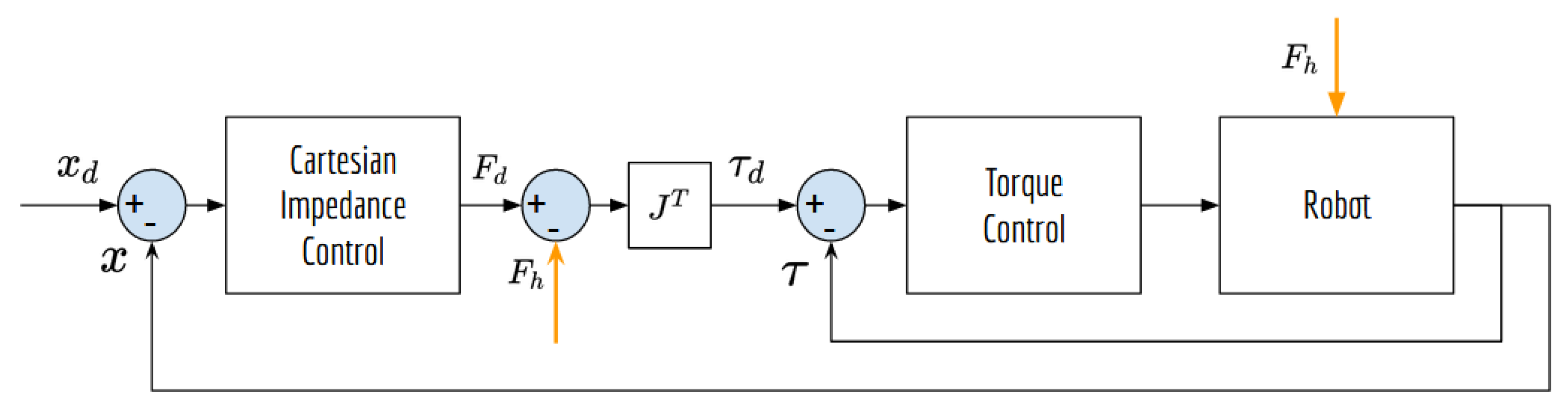
- Force amplification strategy
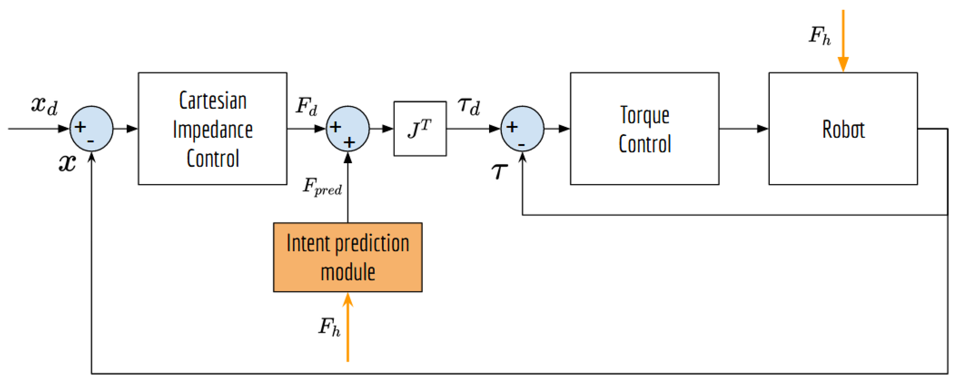
- Intent prediction strategy
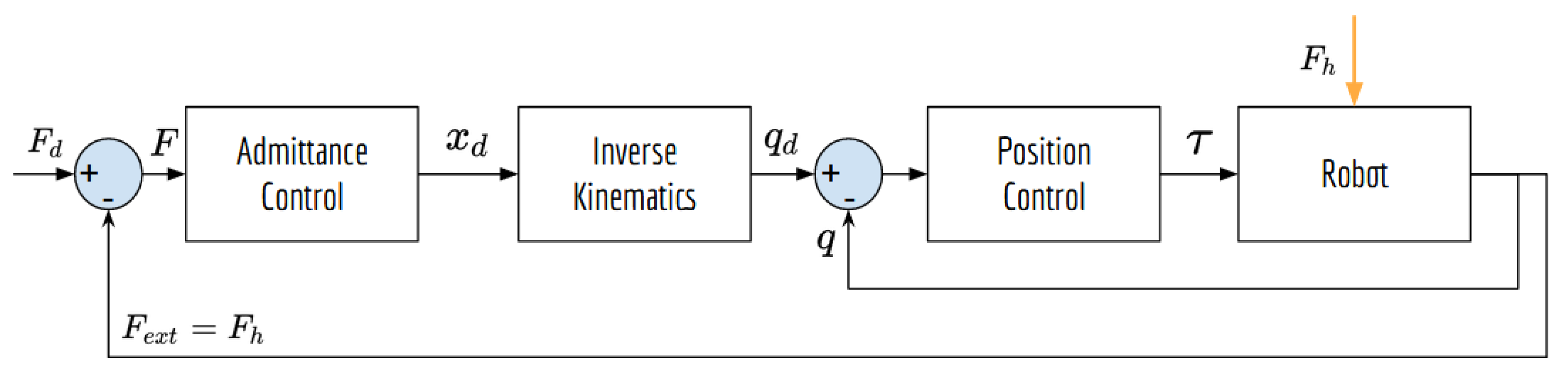
3.2. Impedance Control
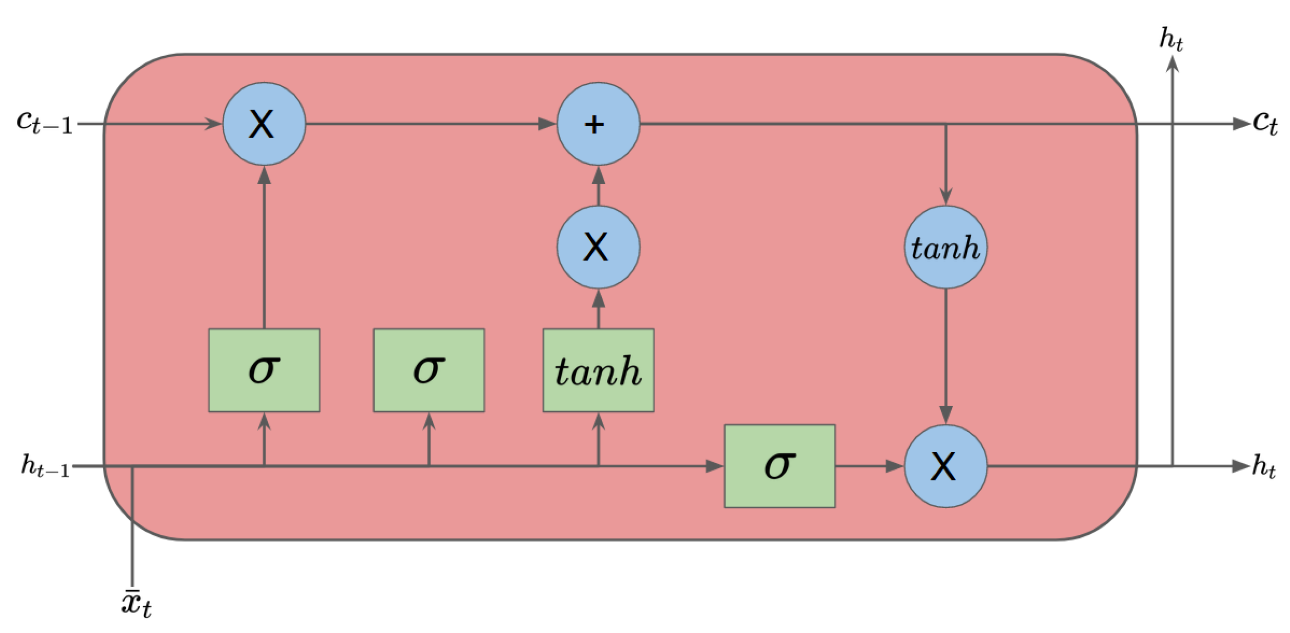
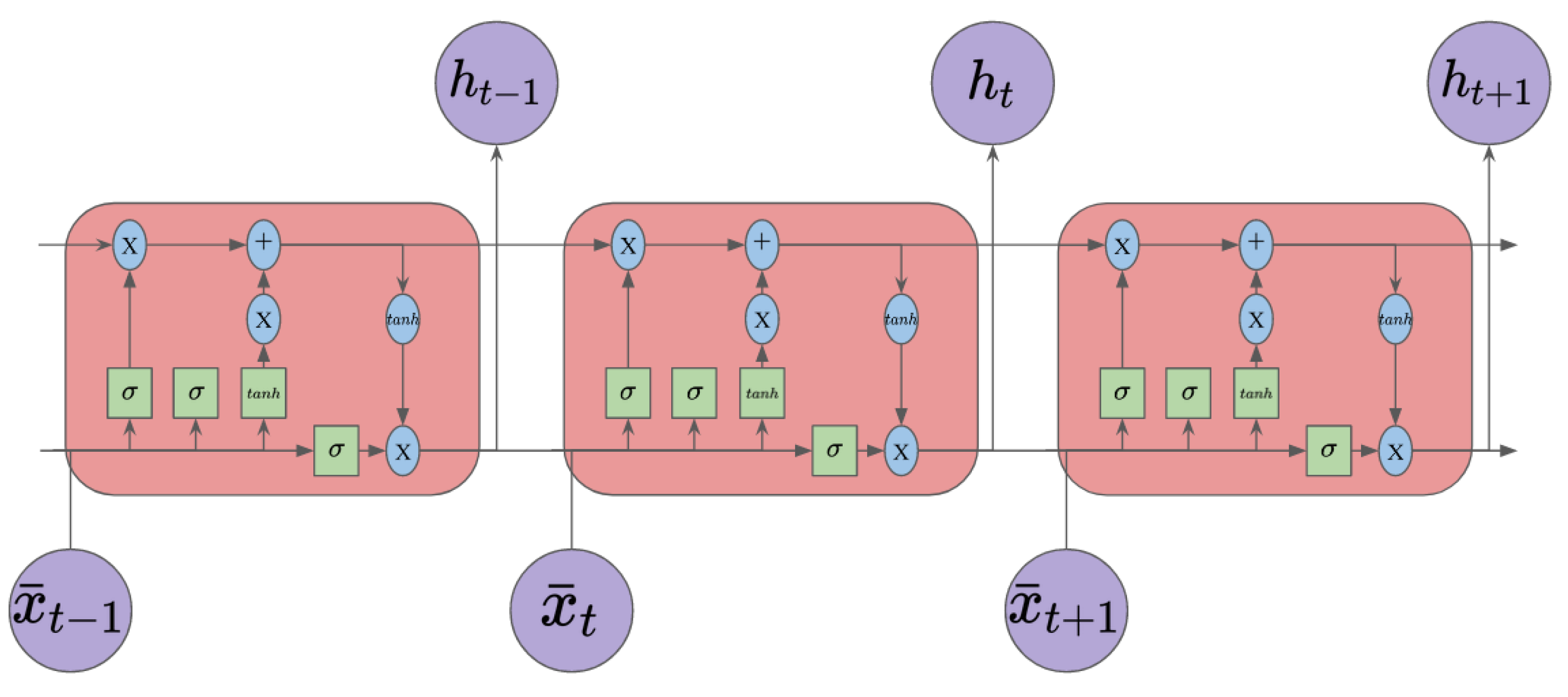
3.3. Long Short-Term Memory Model
- An input gate (i).
- An output gate (o).
- A forget gate (f).
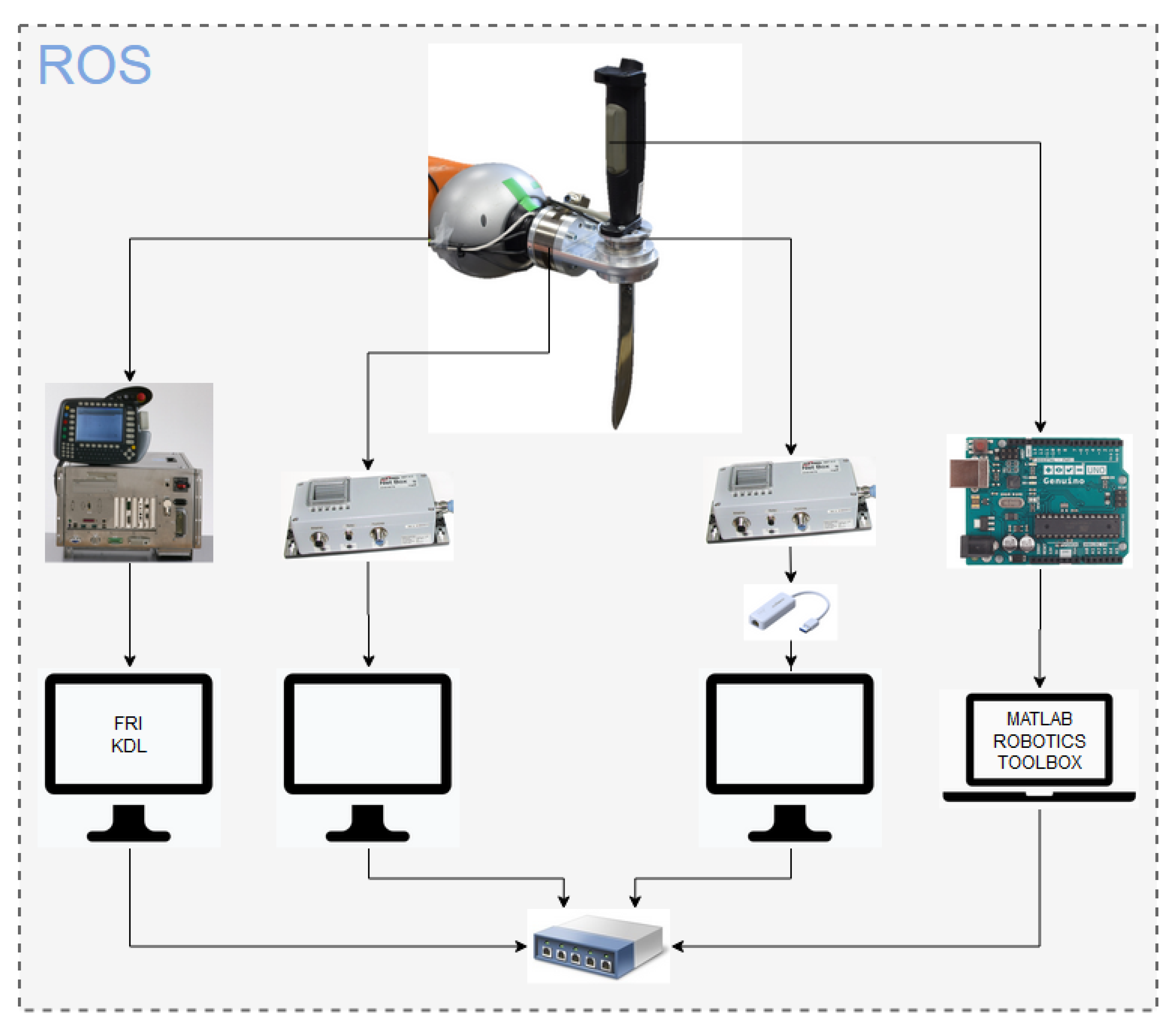
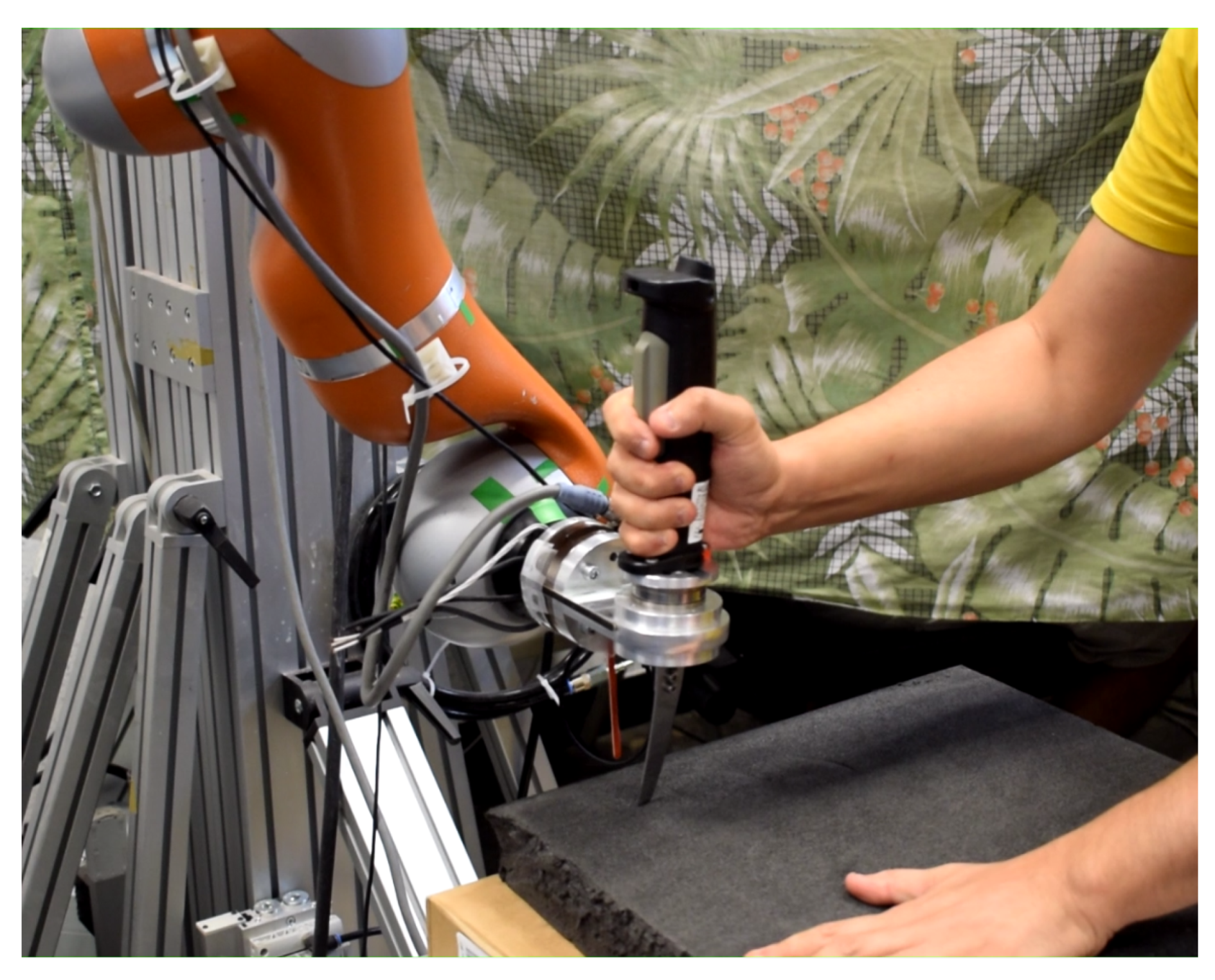
4. Experimental Setup
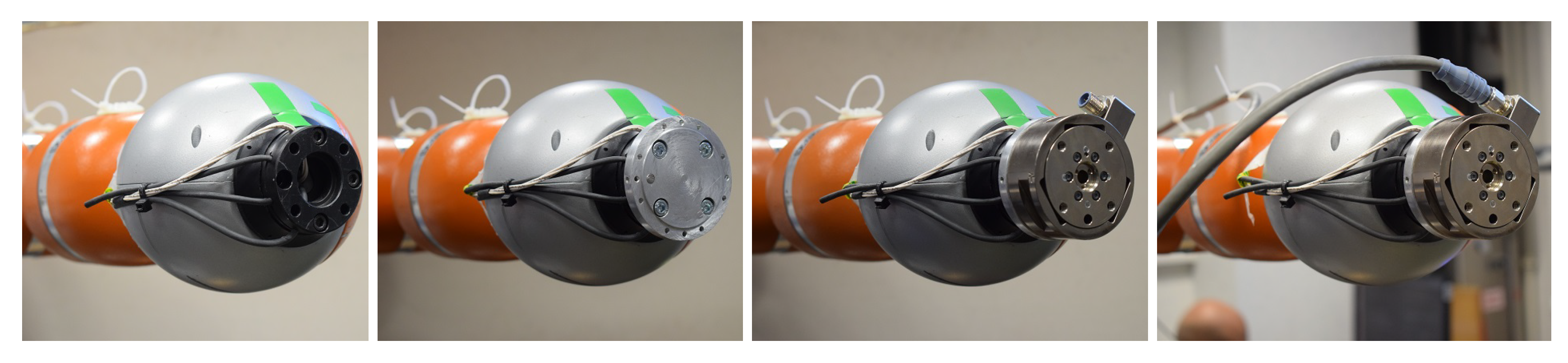
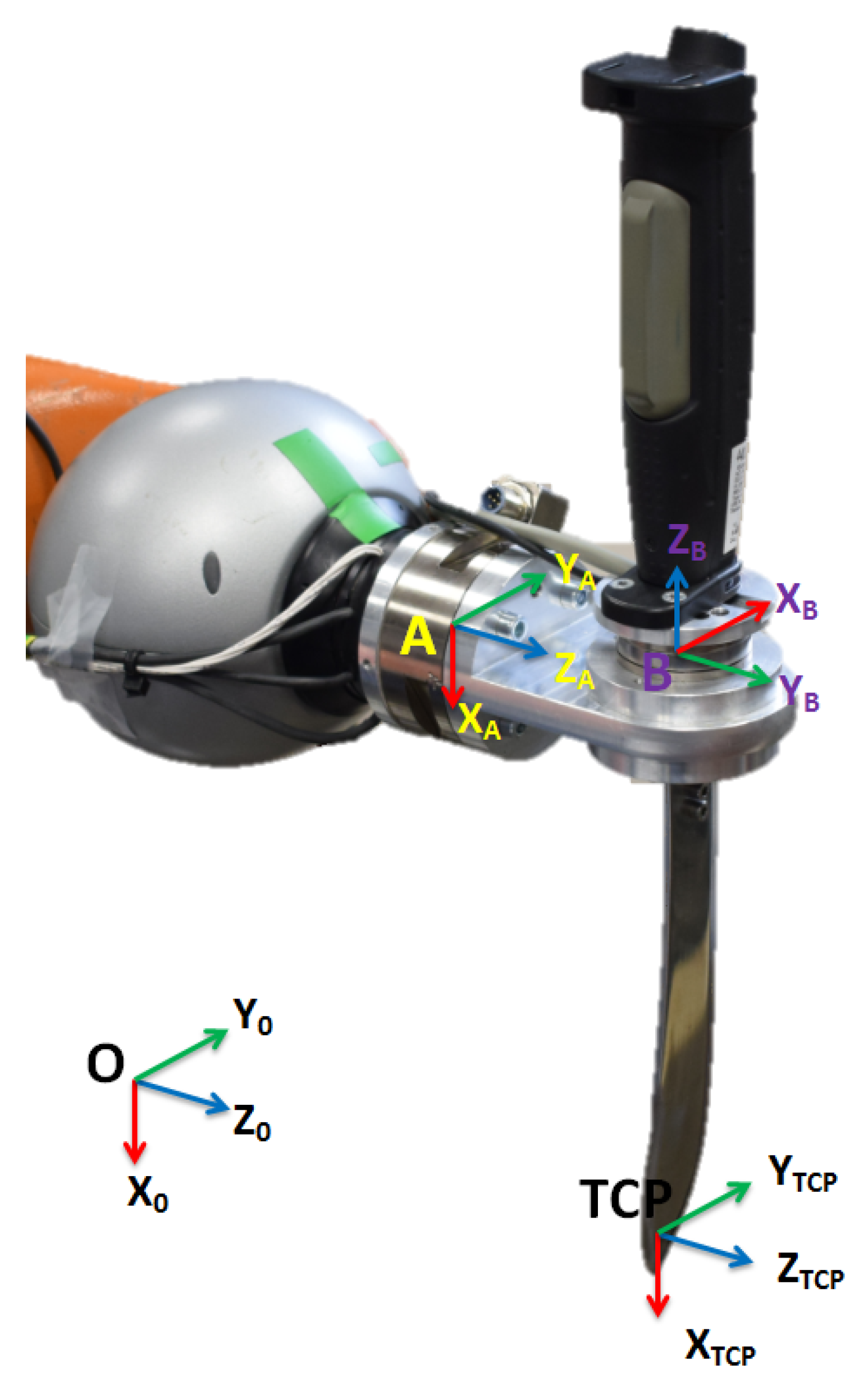
4.1. KUKA LWR Robot
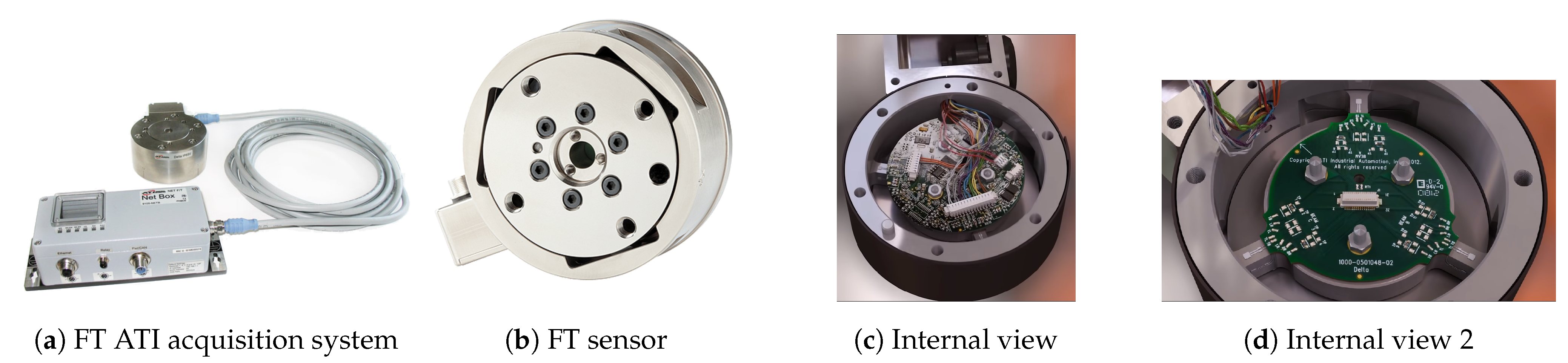
4.2. ATI FT Sensors
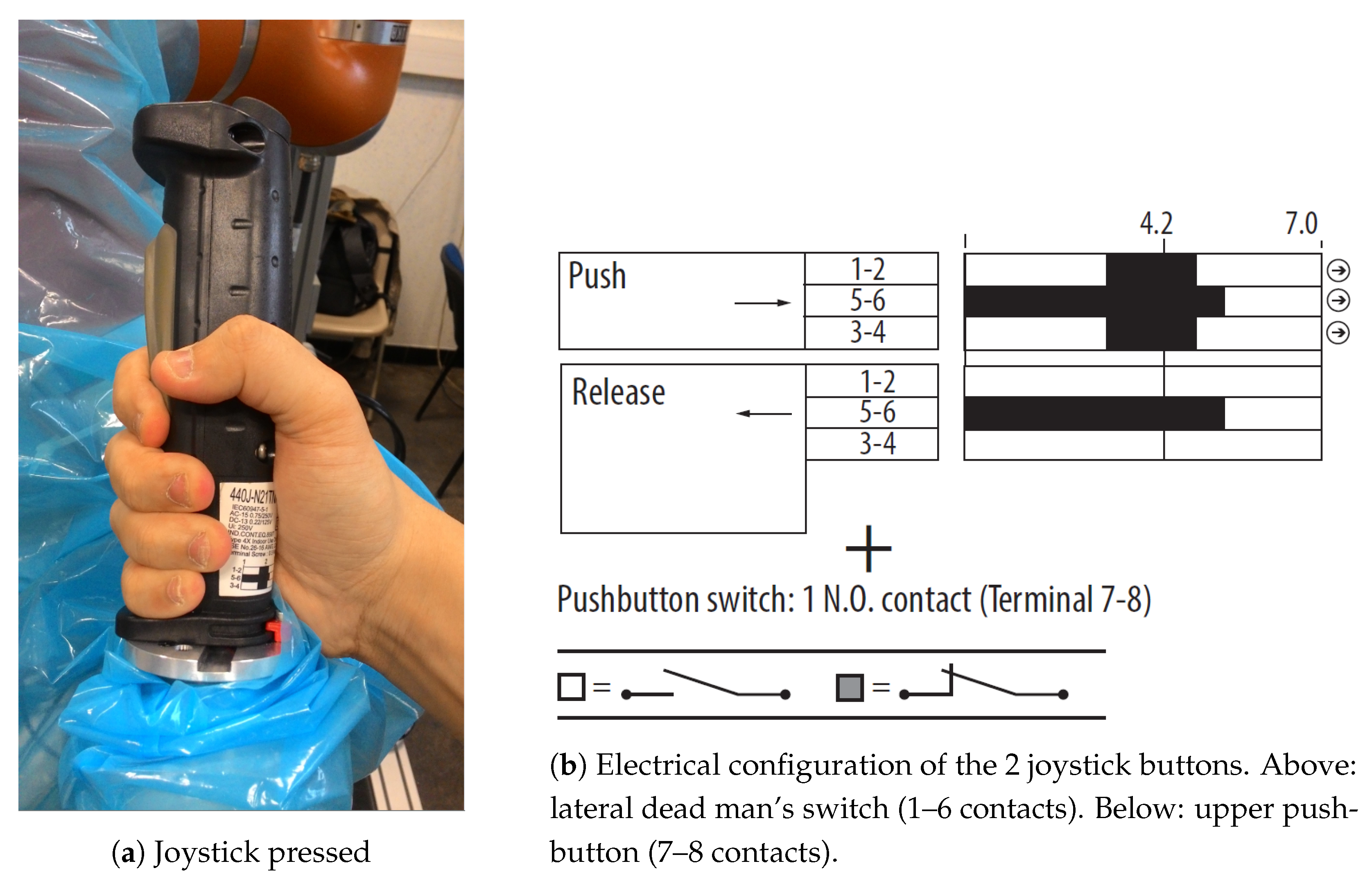
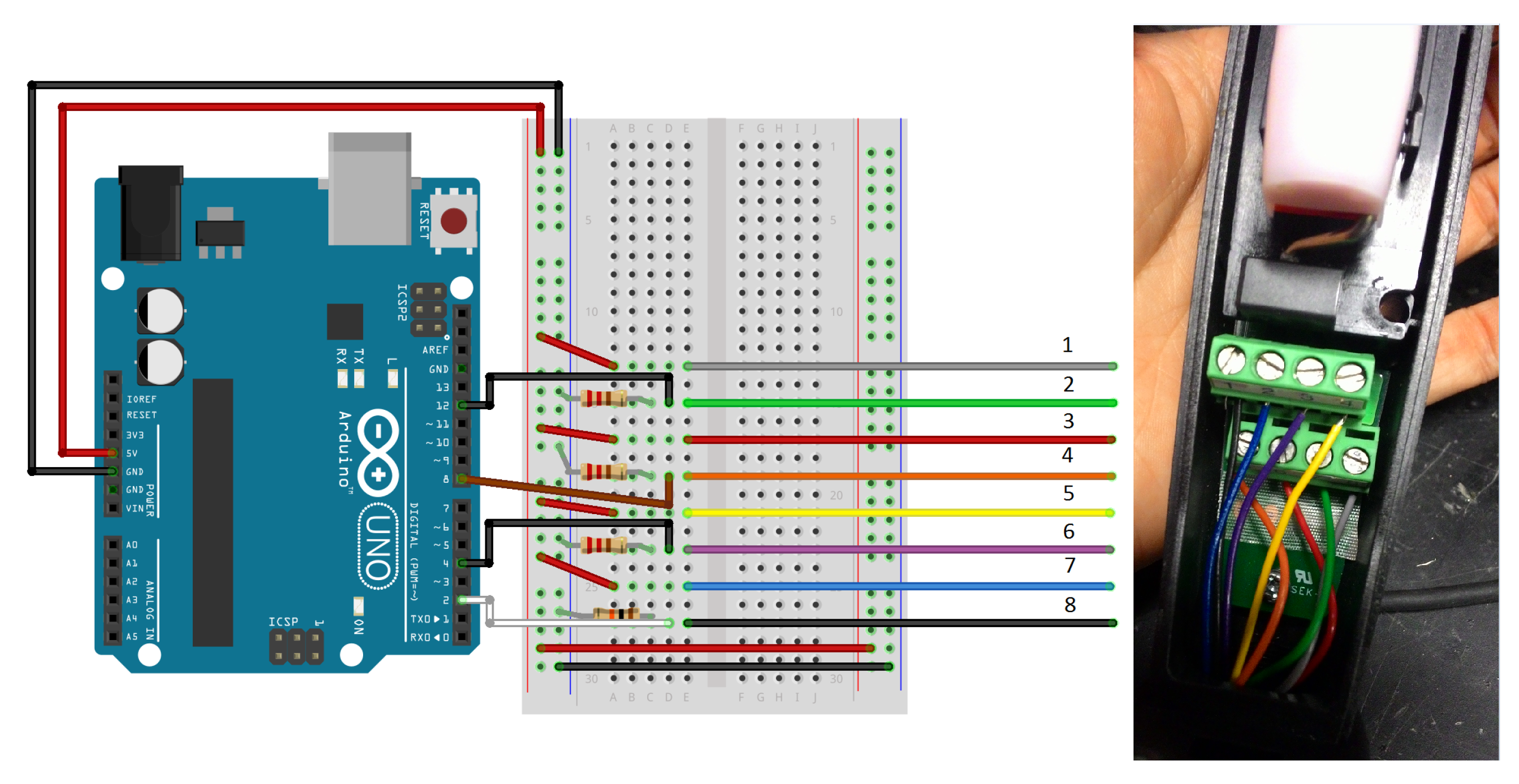
4.3. Allen-Bradley Joystick
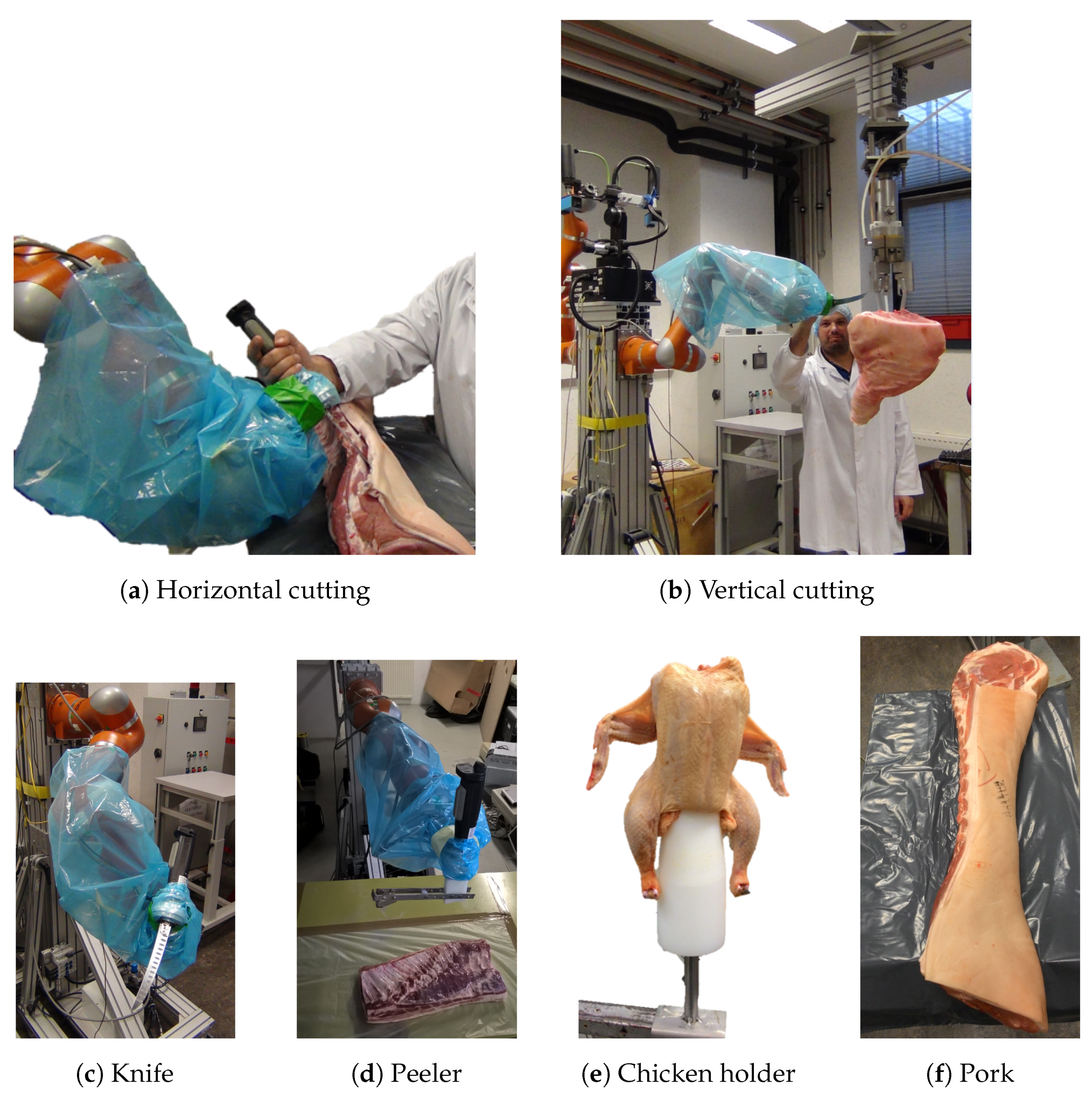
4.4. Meat Cutting Equipment
5. Experiments
- Which FT sensor should be used as a source of input for the control scheme?
- What should the impedance shaping strategy performed through the joystick buttons be?
- What should the amplification factor be for the force amplification strategy?
- Comparison of the force amplification strategy and the intent prediction strategy.
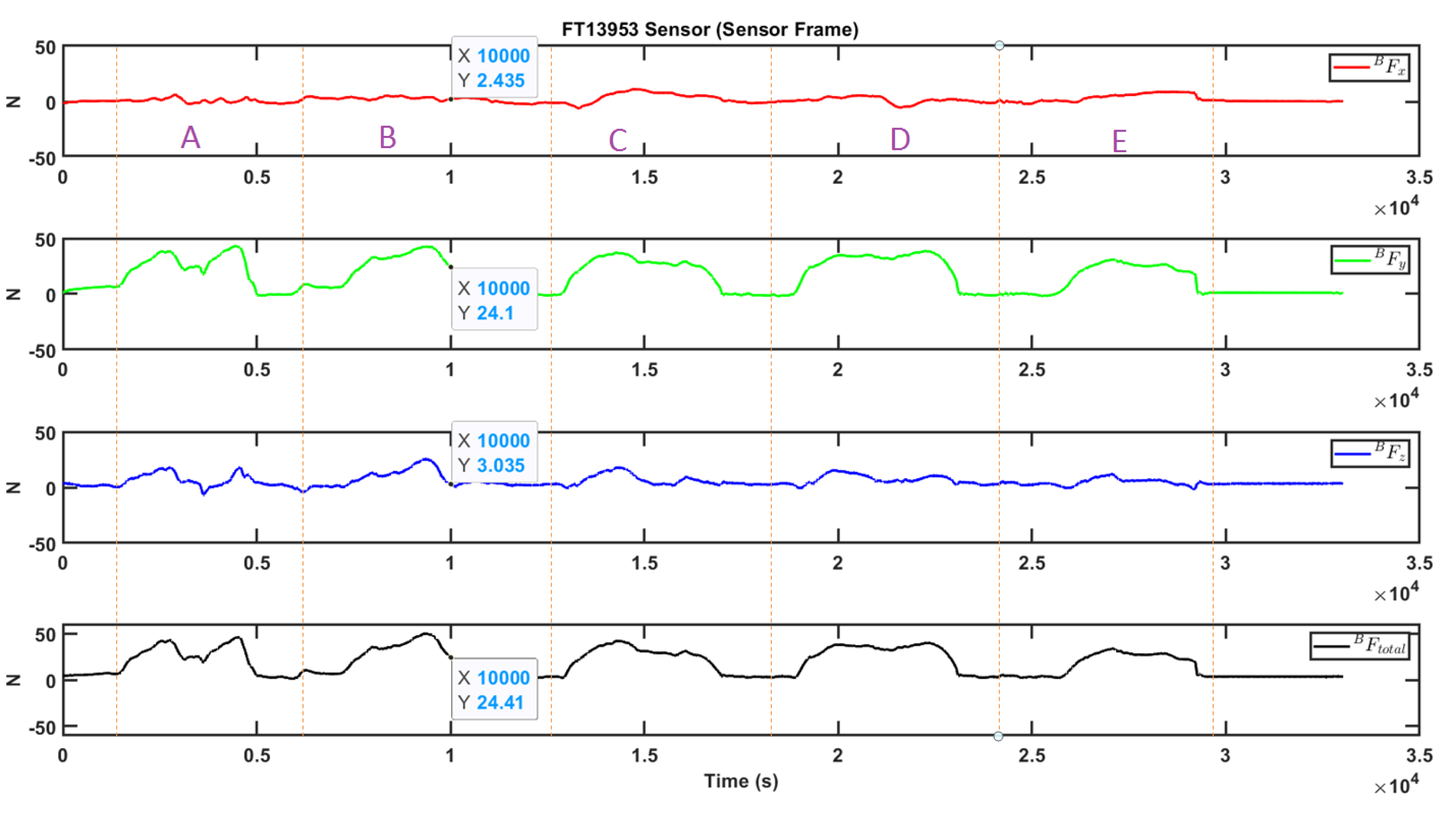
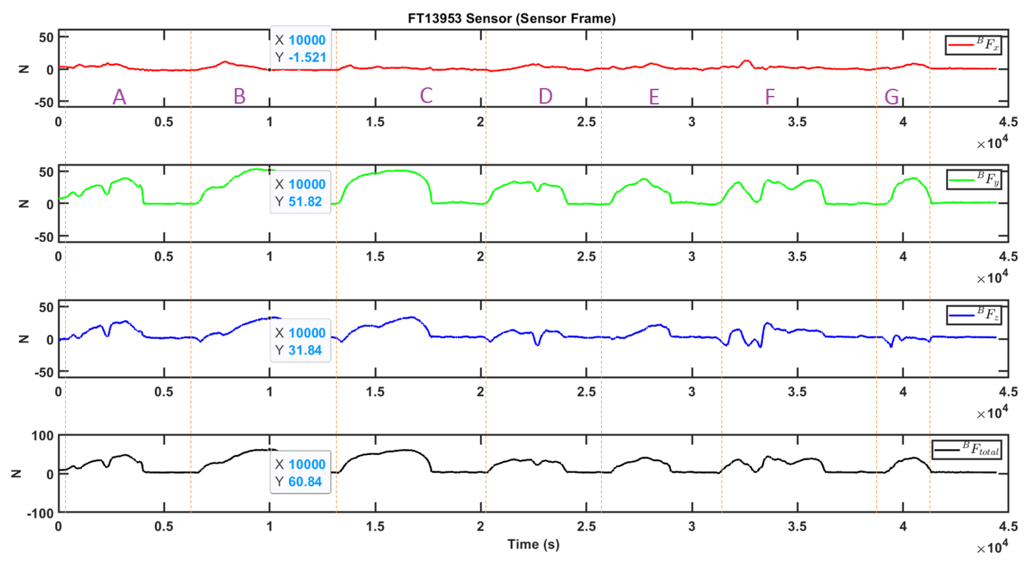
5.1. Comparison of FT Sensors
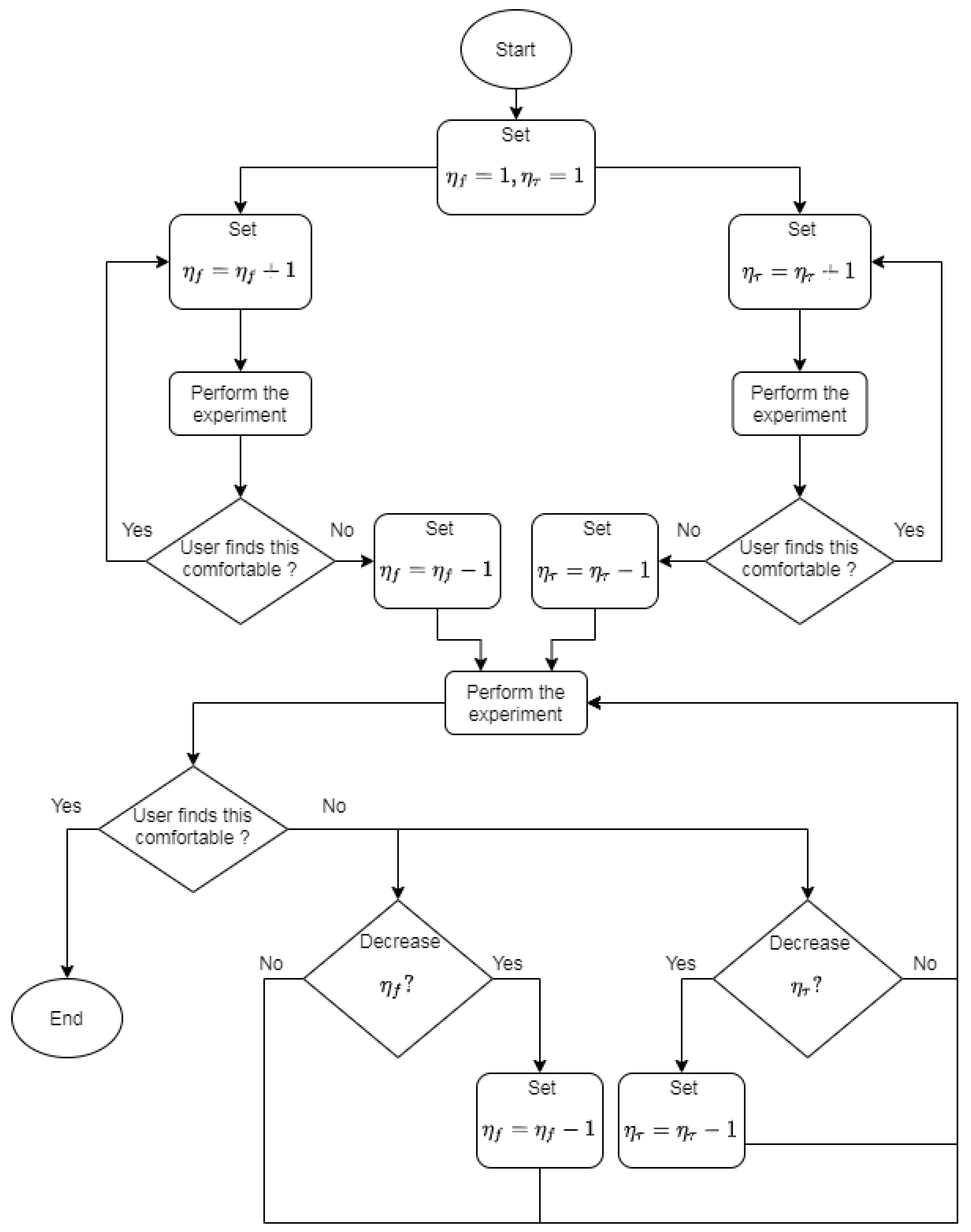
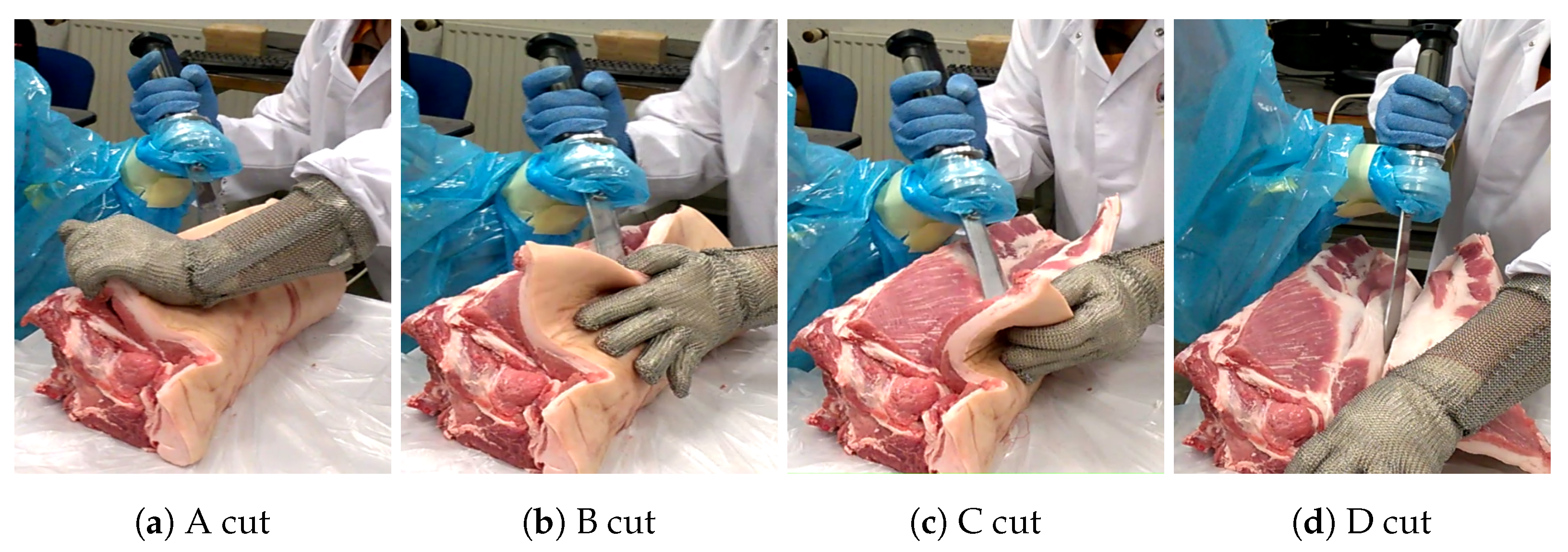
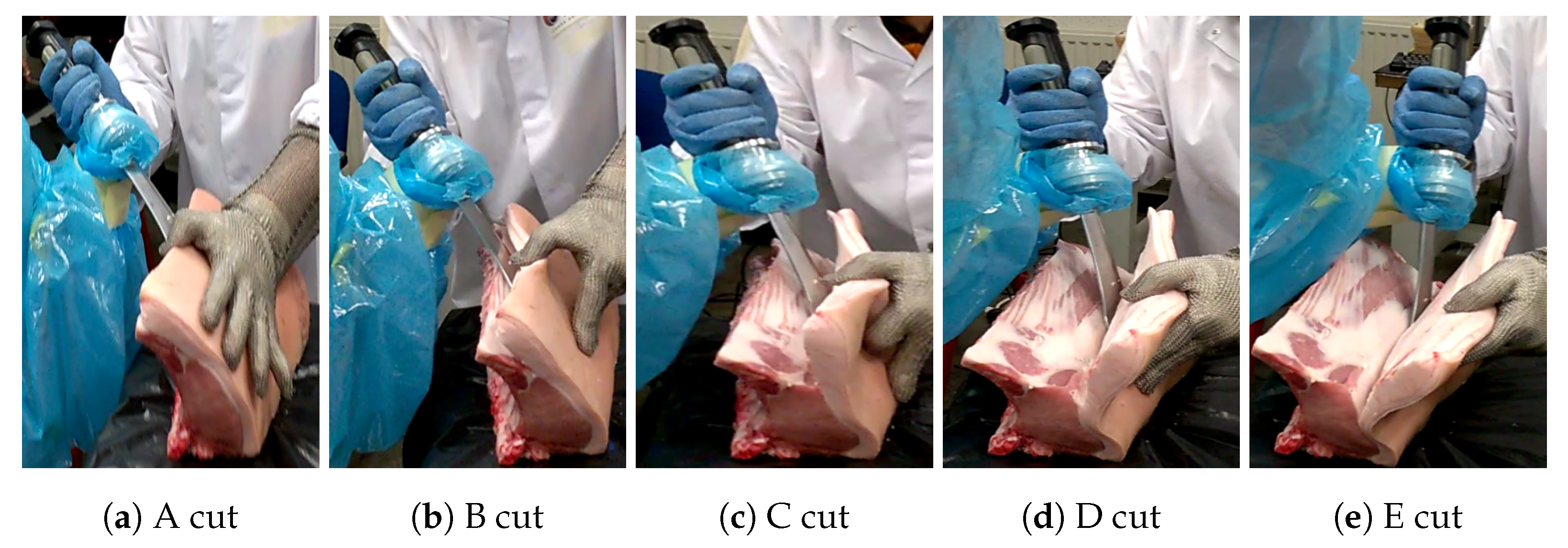
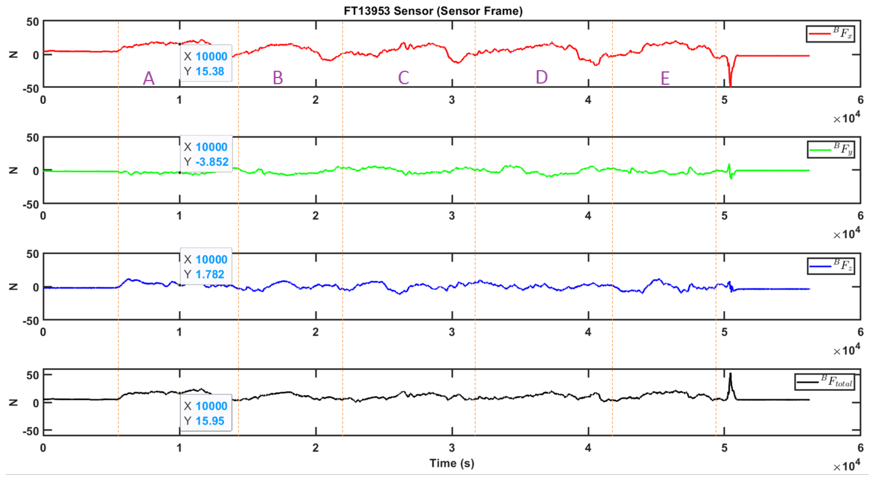
5.2. Impedance Shaping for Cutting
- ,
- ,
- ,
5.3. Tuning the Amplification Factor
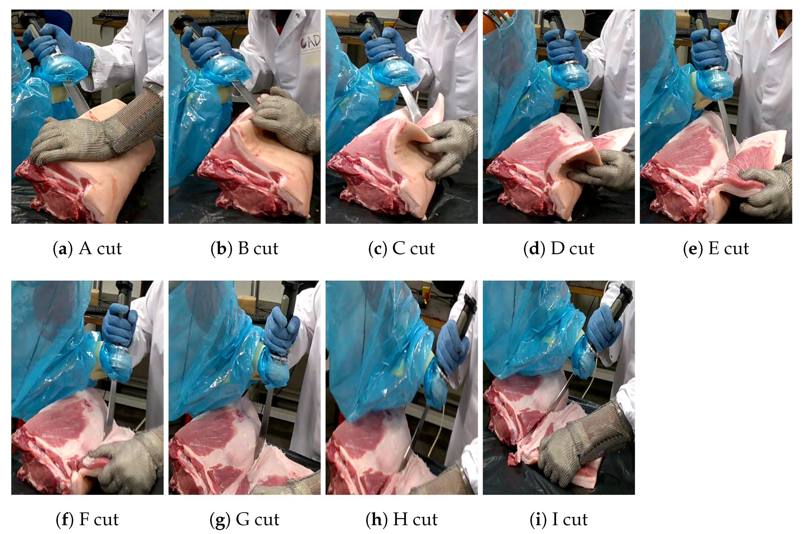
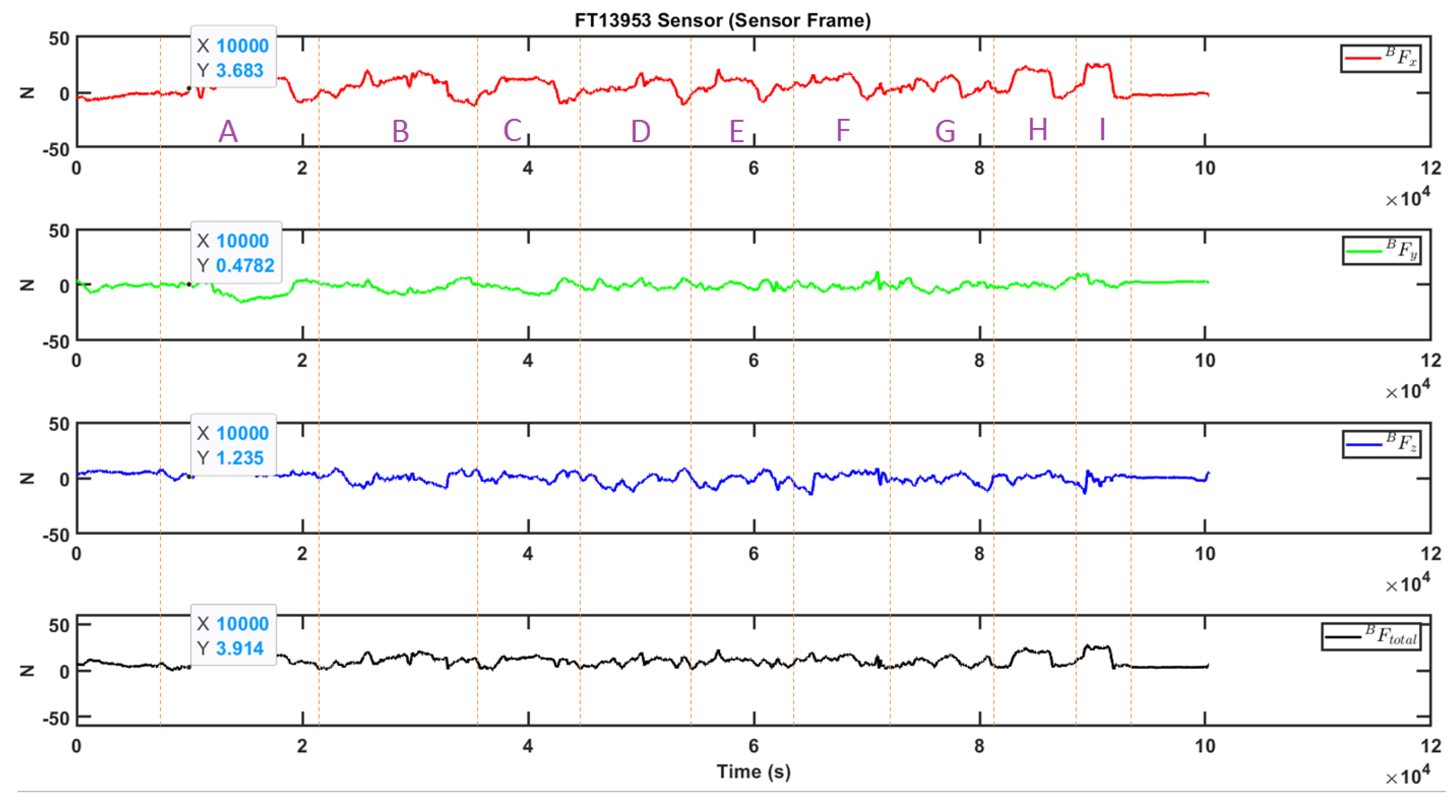
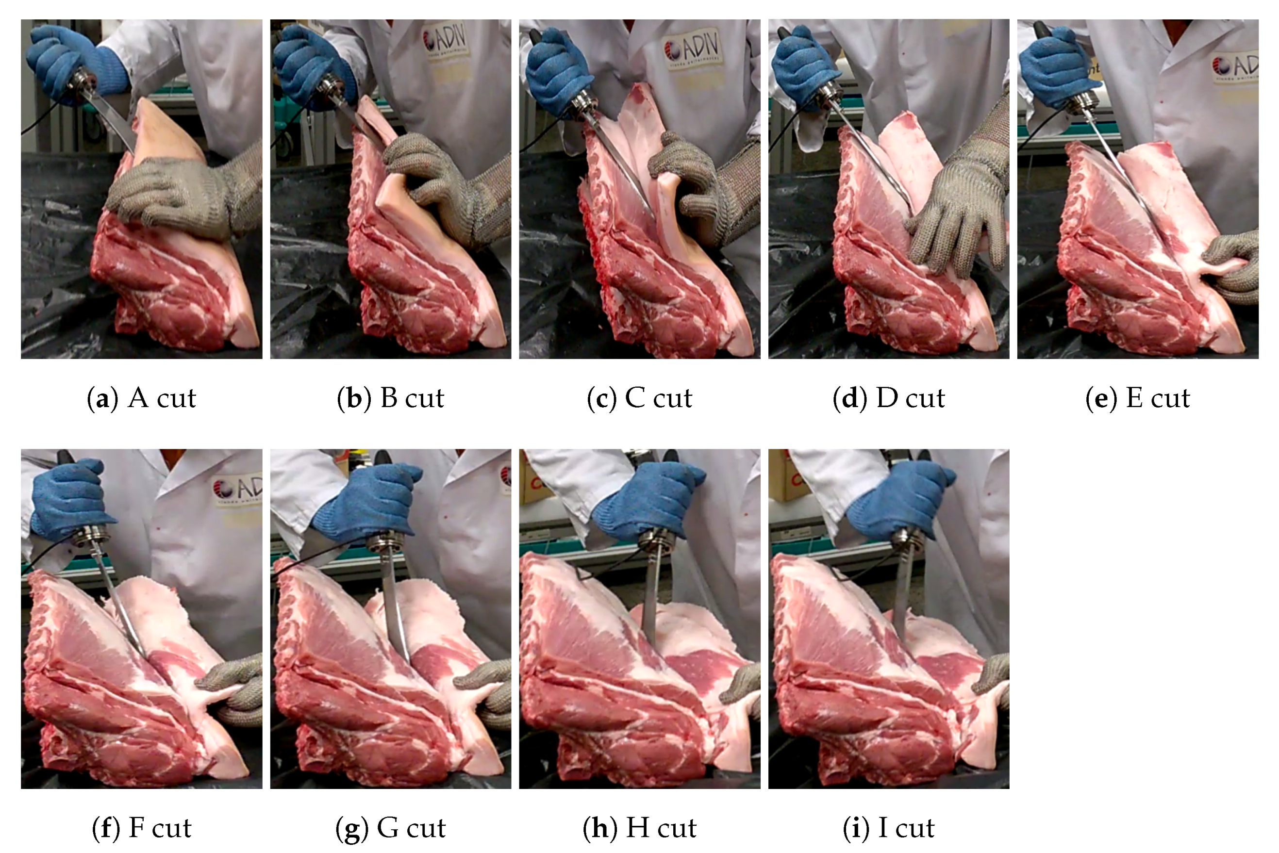
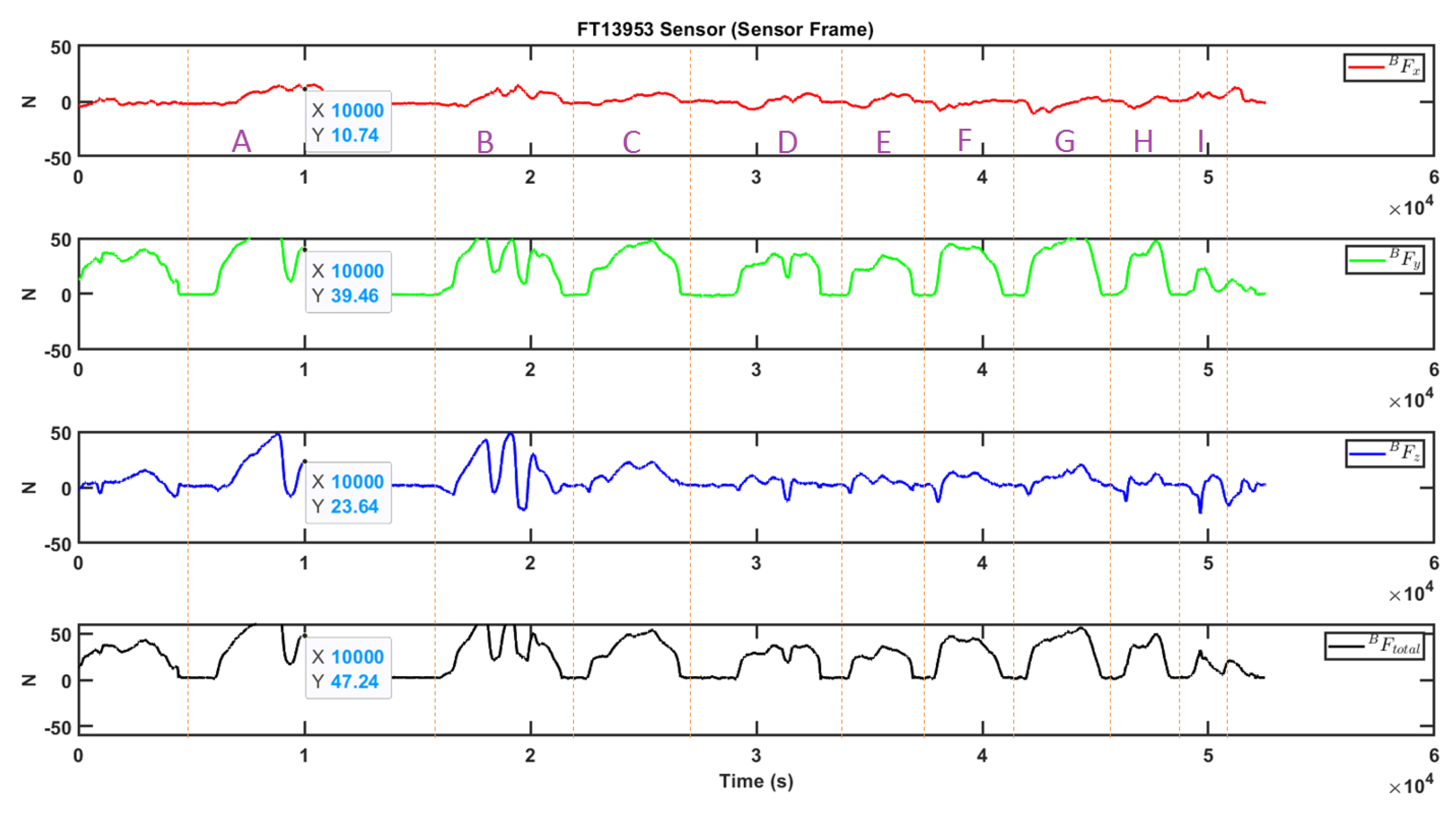
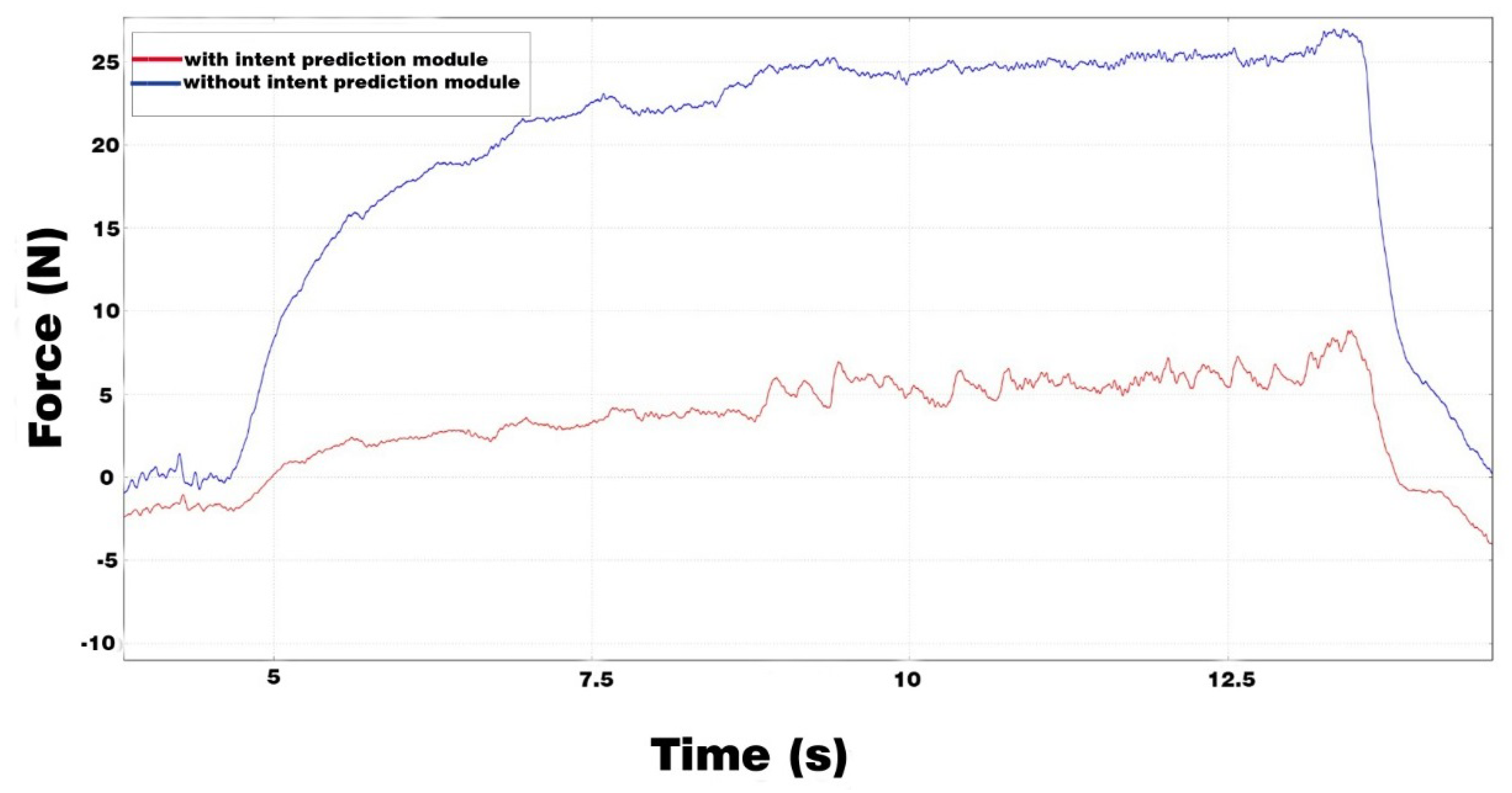
5.4. Meat Cutting with Force Amplification Strategy
6. Conclusions and Future Work
- We followed a systematic methodology to develop a user friendly pHRI controller system for meat cutting.
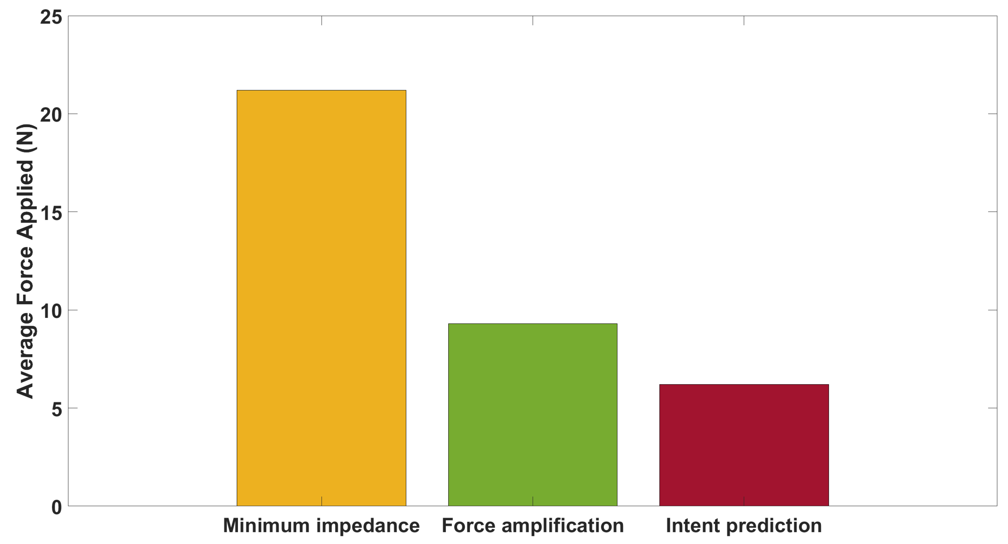
- We developed two assistive strategies: a force amplification strategy and an intent prediction strategy.
- The developed system allowed the user to move the knife in all 6 degrees of freedom.
- Using impedance shaping, the impedance values were altered between the cutting and non-cutting re-positioning movement of the knife, which was found as comfortable by the user.
Author Contributions
Funding
Informed Consent Statement
Conflicts of Interest
Abbreviations
| pHRI | Physical human-robot interaction |
| MSD | Musculoskeletal disorders |
| ARMS | A multi arms Robotic system for Muscle Separation |
| RNN | Recurrent neural networks |
| LSTM | Long Short Term Memory |
| ROS | Robot Operating System |
| FT | Force-Torque |
| URDF | Unified Robot Description Format |
| FRI | Fast Research Interface |
| DH | Denavit–Hartenberg |
| LWR | Light Weight Robot |
| KDL | Kinematics and Dynamics Library |
| IAD | Intelligent Assist Devices |
References
- Statistiques Accidents du Travail et Maladies Professionnelles; Carsat Bretagne: Rennes, France, 2020.
- Rapport Annuel 2019, L’Assurance Maladie-Risques Professionels, Éléments Statistiques et Financiers; Caisse nationale de l’Assurance Maladie des travailleurs salariés: Paris, France, 2020.
- État de Santé des Salariés de la Filière Viande du Régime Agricole en Bretagne; Institut de Veille Sanitaire: Saint-Maurice, France, 2019.
- De Medeiros Esper, I.; From, P.J.; Mason, A. Robotisation and intelligent systems in abattoirs. Trends Food Sci. Technol. 2021, 108, 214–222. [Google Scholar] [CrossRef]
- Long, P.; Khalil, W.; Martinet, P. Modeling control of a meat-cutting robotic cell. In Proceedings of the 2013 16th International Conference on Advanced Robotics (ICAR), Montevideo, Uruguay, 25–29 November 2013; pp. 1–6. [Google Scholar] [CrossRef]
- Long, P.; Khalil, W.; Martinet, P. Robotic cutting of soft materials using force control image moments. In Proceedings of the 2014 13th International Conference on Control Automation Robotics Vision (ICARCV), Singapore, 10–12 December 2014; pp. 474–479. [Google Scholar] [CrossRef]
- Long, P.; Khalil, W.; Martinet, P. Force/vision control for robotic cutting of soft materials. In Proceedings of the 2014 IEEE/RSJ International Conference on Intelligent Robots and Systems, Chicago, IL, USA, 14–18 September 2014; pp. 4716–4721. [Google Scholar] [CrossRef]
- Misimi, E.; Øye, E.R.; Eilertsen, A.; Mathiassen, J.R.; Åsebø, O.B.; Gjerstad, T.; Buljo, J.; Skotheim, Ø. GRIBBOT—Robotic 3D vision-guided harvesting of chicken fillets. Comput. Electron. Agric. 2016, 121, 84–100. [Google Scholar] [CrossRef]
- Wei, G.; Stephan, F.; Aminzadeh, V.; Dai, J.S.; Gogu, G. DEXDEB—Application of DEXtrous Robotic Hands for DEBoning Operation. In Gearing up and Accelerating Cross-Fertilization Between Academic and Industrial Robotics Research in Europe; Röhrbein, F., Veiga, G., Natale, C., Eds.; Springer International Publishing: Cham, Switzerland, 2014; pp. 217–235. [Google Scholar]
- Alric, M.; Stephan, F.; Sabourin, L.; Subrin, K.; Gogu, G.; Mezouar, Y. Robotic solutions for meat cutting and handling. In European Workshop on Deformable Object Manipulation; Innorobo: Lyon, France, 2014. [Google Scholar]
- Lawitzky, M.; Mörtl, A.; Hirche, S. Load sharing in human-robot cooperative manipulation. In Proceedings of the 19th International Symposium in Robot and Human Interactive Communication, Viareggio, Italy, 13–15 September 2010; pp. 185–191. [Google Scholar] [CrossRef]
- Reinkensmeyer, D.J.; Wolbrecht, E.; Bobrow, J. A computational model of human-robot load sharing during robot-assisted arm movement training after stroke. In Proceedings of the 2007 29th Annual International Conference of the IEEE Engineering in Medicine and Biology Society, Lyon, France, 22–26 August 2007; pp. 4019–4023. [Google Scholar]
- Mörtl, A.; Lawitzky, M.; Kucukyilmaz, A.; Sezgin, M.; Basdogan, C.; Hirche, S. The role of roles: Physical cooperation between humans and robots. Int. J. Robot. Res. 2012, 31, 1656–1674. [Google Scholar] [CrossRef]
- Dumora, J.; Geffard, F.; Bidard, C.; Aspragathos, N.A.; Fraisse, P. Robot assistance selection for large object manipulation with a human. In Proceedings of the 2013 IEEE International Conference on Systems, Man, and Cybernetics, Manchester, UK, 13–16 October 2013; pp. 1828–1833. [Google Scholar]
- Medina, J.R.; Lawitzky, M.; Molin, A.; Hirche, S. Dynamic strategy selection for physical robotic assistance in partially known tasks. In Proceedings of the 2013 IEEE International Conference on Robotics and Automation, Karlsruhe, Germany, 6–10 May 2013; pp. 1180–1186. [Google Scholar]
- Erden, M.S.; Marić, B. Assisting manual welding with robot. Robot. Comput. Integr. Manuf. 2011, 27, 818–828. [Google Scholar] [CrossRef]
- Colgate, J.E.; Peshkin, M.; Klostermeyer, S.H. Intelligent assist devices in industrial applications: A review. In Proceedings of the 2003 IEEE/RSJ International Conference on Intelligent Robots and Systems (IROS 2003), Las Vegas, NV, USA, 27–31 October 2003; 3, pp. 2516–2521. [Google Scholar] [CrossRef]
- Paxman, J.; Liu, D.; Wu, P.; Dissanayake, G. Cobotics for Meat Processing: An Investigation into Technologies Enabling Robotic Assistance for Workers in the Meat Processing Industry; Technical Report; University of Technology: Sydney, Australia, 2006. [Google Scholar]
- Campeau-Lecours, A.; Otis, M.J.D.; Gosselin, C. Modeling of physical human–robot interaction: Admittance controllers applied to intelligent assist devices with large payload. Int. J. Adv. Robot. Syst. 2016, 13. [Google Scholar] [CrossRef]
- Lamy, X.; Collédani, F.; Geffard, F.; Measson, Y.; Morel, G. Overcoming human force amplification limitations in comanipulation tasks with industrial robot. In Proceedings of the 2010 8th World Congress on Intelligent Control and Automation, Jinan, China, 7–9 July 2010; pp. 592–598. [Google Scholar] [CrossRef]
- Duchaine, V.; Gosselin, C.M. Investigation of human-robot interaction stability using Lyapunov theory. In Proceedings of the 2008 IEEE International Conference on Robotics and Automation, Pasadena, CA, USA, 19–23 May 2008; pp. 2189–2194. [Google Scholar]
- Dimeas, F.; Aspragathos, N. Online stability in human-robot cooperation with admittance control. IEEE Trans. Haptics 2016, 9, 267–278. [Google Scholar] [CrossRef] [PubMed]
- Maithani, H.; Ramon, J.A.C.; Mezouar, Y. Predicting Human Intent for Cooperative Physical Human-Robot Interaction Tasks. In Proceedings of the 2019 IEEE 15th International Conference on Control and Automation (ICCA), Edinburgh, UK, 6–9 July 2019; pp. 1523–1528. [Google Scholar] [CrossRef]
- Grafakos, S.; Dimeas, F.; Aspragathos, N. Variable admittance control in pHRI using EMG-based arm muscles co-activation. In Proceedings of the 2016 IEEE International Conference on Systems, Man, and Cybernetics (SMC), Budapest, Hungary, 9–12 October 2016; pp. 001900–001905. [Google Scholar]
- Hochreiter, S.; Schmidhuber, J. Long short-term memory. Neural Comput. 1997, 9, 1735–1780. [Google Scholar] [CrossRef] [PubMed]
- Albu-Schäffer, A.; Haddadin, S.; Ott, C.; Stemmer, A.; Wimböck, T.; Hirzinger, G. The DLR lightweight robot: Design and control concepts for robots in human environments. Ind. Robot. Int. J. 2007, 34, 376–385. [Google Scholar] [CrossRef]
- Bischoff, R.; Kurth, J.; Schreiber, G.; Koeppe, R.; Albu-Schäffer, A.; Beyer, A.; Eiberger, O.; Haddadin, S.; Stemmer, A.; Grunwald, G.; et al. The KUKA-DLR Lightweight Robot arm-a new reference platform for robotics research and manufacturing. In Proceedings of the ISR 2010 (41st International Symposium on Robotics) and ROBOTIK 2010 (6th German Conference on Robotics), VDE, Munich, Germany, 7–9 June 2010; pp. 1–8. [Google Scholar]
- Albu-Schaffer, A.; Hirzinger, G. Cartesian impedance control techniques for torque controlled light-weight robots. In Proceedings of the 2002 IEEE International Conference on Robotics and Automation (Cat. No. 02CH37292), Washington, DC, USA, 11–15 May 2002; 1, pp. 657–663. [Google Scholar]
- Schreiber, G.; Stemmer, A.; Bischoff, R. The fast research interface for the kuka lightweight robot. In Proceedings of the IEEE Workshop on Innovative Robot Control Architectures for Demanding (Research) Applications How to Modify and Enhance Commercial Controllers (ICRA 2010), Anchorage, AK, USA, 3–7 May 2010; pp. 15–21. [Google Scholar]
- KUKA LWR Document Manual; KUKA Roboter GmbH: Augsburg, Germany, 2010.
- Quigley, M.; Conley, K.; Gerkey, B.; Faust, J.; Foote, T.; Leibs, J.; Wheeler, R.; Ng, A.Y. ROS: An open-source Robot Operating System. In ICRA Workshop on Open Source Software; IEEE ICRA 2009: Kobe, Japan, 2009; Volume 3, p. 5. [Google Scholar]
- Available online: http://docs.ros.org/indigo/api/orocos_kdl/html/ (accessed on 21 April 2021).
- Corke, P. Robotics, Vision and Control: Fundamental Algorithms in MATLAB® Second Edition, Completely Revised; Springer: Berlin/Heidelberg, Germany, 2017; Volume 118. [Google Scholar]
- Available online: https://in.mathworks.com/help/robotics/ (accessed on 21 April 2021).


| Joints | (m) | (rad) | (rad) | (Nm) | ||||
|---|---|---|---|---|---|---|---|---|
| J1 | A1 | 0.3105 | 0 | /2 | −170 | 170 | 176 | |
| J2 | A2 | 0 | 0 | /2 | −120 | 120 | 176 | |
| J3 | E1 | 0.4 | 0 | −/2 | −170 | 170 | 100 | |
| J4 | A3 | 0 | 0 | /2 | −120 | 120 | 100 | |
| J5 | A4 | 0.39 | 0 | /2 | −170 | 170 | 100 | |
| J6 | A5 | 0 | 0 | −/2 | −120 | 120 | 38 | |
| J7 | A6 | 0.078 | 0 | 0 | −170 | 170 | 38 |
| Joints | x (m) | y (m) | z (m) | r | p | y | Axis | |
|---|---|---|---|---|---|---|---|---|
| A1 | 0 | 0 | 0.11 | 0 | 0 | 0 | [0 0 1] | +z axis |
| A2 | 0 | 0 | 0.2005 | 0 | 0 | 0 | [0 −1 0] | −y axis |
| E1 | 0 | 0 | 0.2 | 0 | 0 | 0 | [0 0 1] | +z axis |
| A3 | 0 | 0 | 0.2 | 0 | 0 | 0 | [0 1 0] | +y axis |
| A4 | 0 | 0 | 0.2 | 0 | 0 | 0 | [0 0 1] | +z axis |
| A5 | 0 | 0 | 0.19 | 0 | 0 | 0 | [0 −1 0] | −y axis |
| A6 | 0 | 0 | 0.078 | 0 | 0 | 0 | [0 0 1] | +z axis |
| Robot World Frame | Sensor A (FT13855) | Sensor B (FT13953) | Relation |
|---|---|---|---|
| X | X | −Z | X X −Z |
| Y | Y | X | Y X X |
| Z | Z | Y | Z Z Y |
| Button 2 | |||
|---|---|---|---|
| State 0 | State 1 | ||
| Button 1 | Position 0 | Robot is stiff + no amplification | Robot is stiff + amplification |
| Position 1 | Robot is free, but no amplification (used for positioning of knife) | Robot is free + amplification (used for cutting) | |
| Position 2 | Robot is free, but no amplification (used for positioning of knife) | Robot is free + amplification (used for cutting) | |
| Button 2 | |||
|---|---|---|---|
| State 0 | State 1 | ||
| Button 1 | Position 0 | ||
| Position 1 | (used for positioning of knife) | (used for cutting) | |
| Position 2 | (used for positioning of knife) | (used for cutting) | |
| S.No. | Meat | Part | Side | Operation | FT Sensor Input | Force Amplification | Torque Amplification |
|---|---|---|---|---|---|---|---|
| 1 | Pork | Square | Right | Cutting | B | 20 | 3 |
| 2 | Pork | Square | Right | Cutting | B | 20 | 3 |
| 3 | Pork | Square | Right | Cutting | B | 15 | 3 |
| 4 | Pork | Square | Right | Cutting | B | 15 | 3 |
| 5 | Pork | Square | Right | Cutting | B | 10 | 3 |
| 6 | Pork | Square | Right | Cutting | B | 20 | 3 |
Publisher’s Note: MDPI stays neutral with regard to jurisdictional claims in published maps and institutional affiliations. |
© 2021 by the authors. Licensee MDPI, Basel, Switzerland. This article is an open access article distributed under the terms and conditions of the Creative Commons Attribution (CC BY) license (https://creativecommons.org/licenses/by/4.0/).
Share and Cite
Maithani, H.; Corrales Ramon, J.A.; Lequievre, L.; Mezouar, Y.; Alric, M. Exoscarne: Assistive Strategies for an Industrial Meat Cutting System Based on Physical Human-Robot Interaction. Appl. Sci. 2021, 11, 3907. https://doi.org/10.3390/app11093907
Maithani H, Corrales Ramon JA, Lequievre L, Mezouar Y, Alric M. Exoscarne: Assistive Strategies for an Industrial Meat Cutting System Based on Physical Human-Robot Interaction. Applied Sciences. 2021; 11(9):3907. https://doi.org/10.3390/app11093907
Chicago/Turabian StyleMaithani, Harsh, Juan Antonio Corrales Ramon, Laurent Lequievre, Youcef Mezouar, and Matthieu Alric. 2021. "Exoscarne: Assistive Strategies for an Industrial Meat Cutting System Based on Physical Human-Robot Interaction" Applied Sciences 11, no. 9: 3907. https://doi.org/10.3390/app11093907
APA StyleMaithani, H., Corrales Ramon, J. A., Lequievre, L., Mezouar, Y., & Alric, M. (2021). Exoscarne: Assistive Strategies for an Industrial Meat Cutting System Based on Physical Human-Robot Interaction. Applied Sciences, 11(9), 3907. https://doi.org/10.3390/app11093907