Article

Additive Manufacturing in the Construction Industry: The Comparative Competitiveness of 3D Concrete Printing

1
Department of Industrial Engineering and Management, Aalto University, 00076 Aalto, Finland
2
Department of Civil Engineering, Aalto University, 00076 Aalto, Finland
3
Department of Architecture, Aalto University, 00076 Aalto, Finland
4
Singapore Center for 3D printing, Nanyang Technological University, Singapore 639798, Singapore
*
Author to whom correspondence should be addressed.
Appl. Sci. 2021, 11(9), 3865; https://doi.org/10.3390/app11093865
Submission received: 30 March 2021 / Revised: 19 April 2021 / Accepted: 21 April 2021 / Published: 24 April 2021
(This article belongs to the Section Applied Industrial Technologies)

Abstract

:
The construction industry is facing increasing pressure to improve productivity and decrease its environmental impact. Additive manufacturing (AM) technologies, especially three-dimensional concrete printing (3DCP) technology, have provided many benefits for construction. However, holistic comparative studies of the competitiveness of 3DCP and conventional methods, from cost and time perspectives, are lacking. Choosing between the methods is difficult for practitioners. In this study, we investigated the current state of 3DCP in the construction industry using seven distinct scenarios. Our analysis was performed to illustrate the impact of design and supply chain configurations on performance. The results prove the notable competitiveness of 3DCP. In contrast to the conventional construction method, the more complex round design had a positive impact on the cost and process time in 3DCP scenarios. Additionally, we show that on-site 3DCP using a robotic arm was more cost-effective than off-site 3DCP.

1. Introduction

The construction industry is estimated to comprise 13% of the global GDP and has been growing at a rate of 6% over the last five years due to rapid urbanization in countries such as China [1]. Due to the enormous size of the construction industry, its economic and environmental impact cannot be disregarded. In other words, even a modest improvement in the efficiency and effectiveness of the construction industry can have significant implications for the global economy and the world population. Digital transformation might hold the key to such necessary change in the construction industry. While various aspects of human life have been transformed by digitalization during the last 30 years, and industries have been overhauled through digital transformations or even replaced by their digital versions (e.g., the retail and travel industries), the construction industry is known to be lagging behind most other modern industries in terms of digitalization and productivity improvements [2]. The industry has not yet experienced a sizable digital disruption, unlike many other industries.
Three-dimensional printing, also known as additive manufacturing (AM), contributes to digital transformation in the manufacturing sector. AM produces components directly from a digital design file and prints the special raw material layer by layer. Nowadays, AM technology is explored intensively in the construction industry, since it allows designs to be developed and manufactured rapidly [3]. It can also shorten supply chains in the construction industry by autonomously manufacturing components directly from a digital design model with the least possible human intervention [4]. Regarding concrete structures, 3D printing technology enables concrete to be printed at a desired location and at a desired speed, by pumping the concrete toward the printing head [5].
Since 3D printing technology is advancing and making it possible to print complex and large structures such as two-story houses [6] and five-story apartments [7], it is important to investigate the cost and sustainability aspects of 3D concrete printing (3DCP) technology. The construction industry is one of the most inefficient industries; hence, 3D printing technology may disrupt the construction industry operationally and economically. Prior research has shown that complex large-scale structures can be produced via 3DCP technology, and besides introducing automation, the technology can have social and design flexibility benefits [8]. The 3DCP technology offers design freedom, allowing designers to produce flexible designs [9]. Theoretically, 3D printing should allow for any shape to be printed [10] and it has the potential to change the effect of design and supply chain configurations on cost performance. Traditional construction methods have supported the use of standardized design solutions and industrialized prefabrication, but little empirical research has examined how 3D concrete printing might change these relationships.
The typical division of construction into industrialized prefabrication and on-site operations is still relevant for 3D concrete printing, even though AM originally facilitated local on-site production. Moreover, 3DCP can be performed on the production site while the robotic printer and the concrete pump are being transported to the site and installed for printing, which we call on-site printing. Printing can be performed in factories, and the produced components can be shipped to the construction site for assembly. Thus, multiple design and supply chain configurations are possible for 3DCP, and empirical research is needed regarding the cost and time effects of these different supply chain configurations.
The objective of this study was to compare the performance of conventional construction methods with that of 3DCP technology for different design solutions and supply chain configurations. We investigated the competitiveness of concrete printing in terms of cost and completion time to determine the optimal design solutions and supply chain configurations. The study contributes to the existing knowledge about concrete printing technology and the feasibility of its application for housing projects.

2. Literature Review

2.1. Evolution of Production and Design Methods in the Construction Industry

Humanity has engaged in construction since the beginning of history. Construction has evolved through the ages and by the discovery of new materials, means, and methods up to the modern age. During pre-industrial times, labor was the major factor in construction. During the 1900s, a transformation took place, from an agricultural economy to an industrial economy in which coal, steel, and construction businesses gained more importance [11]. The industry finally adopted more mechanized approaches that led to a mature form of technological thinking [12].
Regarding concrete construction methods, reinforced concrete was invented during the second half of the nineteenth century. The main driver for its development was the need for economic and fireproof building materials. The development of modern cement and steel during the first half of the nineteenth century made this invention possible [13]. In 1885, the first skyscraper was built in Chicago, which was the first metal-framed building in history [14]. In 1889, the Eiffel Tower was built by Gustave Eiffel and Maurice Koechlin to demonstrate the potential of iron for building structures [15]. Thus, it can be said that innovation in construction was more technology-driven than market-driven [16].
In 1973, the Sydney Opera House was built by structural engineers using computational analysis software for the first time [17], which was estimated to save 10 years of human work. In the early 2000s, building information modeling (BIM) was introduced to replace CAD solutions, impacting all aspects of building design and development processes [18].
Since the end of the 1980s, some supply chain management developments have been introduced in the construction industry [19], and studies have attempted to integrate the construction supply chain with construction processes [20]. Recently, the role of logistics has become a major concern for construction industry managers [21].

2.2. Construction Supply Chain Configurations: On-Site and Off-Site

Two distinguishable supply chain configurations can be used to supply the final product to customers: a centralized configuration and a distributed configuration [22]. In a centralized configuration, products are produced at a single location, and the raw material is supplied to that location by the suppliers. The end product is then shipped from that single location to all the customers around the world. In the case of construction, the product (i.e., a building) is constructed from components that are prefabricated by a supplier in a central factory. The supplied prefabricated components are then assembled on the site, and finishing work is performed on them to complete the building.
The distributed supply chain concept refers to production facilities located near the points of consumption [23]. In this case, multiple factories in different geographical locations produce products near their points of use. In the case of the construction industry, on-site construction represents a decentralized supply chain, with all the components for production delivered to the production site. The construction and assembly then take place at the production site and are completed with finishing tasks. On-site printing is an example of a decentralized supply chain for construction, since the concrete printer is transported to the construction site and moved around the site as required until the construction is complete.
During the first wave of industrial automation, around the 1980s, the first prefabricated concrete and masonry elements and modules were developed [24]. Prefabrication means assembling building components in a factory or a special facility and then transporting the partially or completely assembled structures to the building location [25]. Prefabrication contributes to standardization and labor reductions [26]. However, it requires extra engineering effort during the design phase and greater initial investment [27]. Moreover, design is limited to combining a set of prefabricated elements.

2.3. Additive Manufacturing and Application for Construction

Additive manufacturing (AM) was invented in the 1980s as a polymer prototyping method. In contrast to conventional manufacturing (CM) methods such as computer numerical control (CNC), AM creates the part geometry using a layer-by-layer process that adds material, rather than subtracting it. Additionally, AM differs from CM forming methods because it is tool-independent, and this makes the AM process much faster than tool-based conventional manufacturing processes for the first part of a production run. Being a toolless process, economies of scale only apply to AM parts until the production chamber is full; thereafter, the cost per part remains constant independently of the production volume. New sorts of structures with dimensional accuracy and evaluation of the morphologies of the structures are possible through 3DCP [28]. Using a concrete mix that satisfies several design and operational constraints, 3D concrete printing can be used without the use of formwork [29].
AM provides construction opportunities such as design flexibility [30,31], automation possibilities [32], digitalization [33], and high precision [34]. Studies have shown that novel shapes can be manufactured via large-scale 3D printing [35]. Using 3D printing for construction reduces the required labor, capital investment, and formwork [36] compared to traditional construction.
Figure 1 shows the generic components of an AM machine used for construction. The main components are the six-axis robotic arm, which moves the concrete nozzle used for printing; the concrete mixer and concrete pump, which feed the concrete to the nozzle; and the robotic arm control unit.

2.4. Gaps in the Existing Knowledge

Previous research has focused on the use of concrete printing for volume production. Three-dimensional printing for construction applications has demonstrated its benefits, such as for one-story house printing in a day in China [37] and a canal house in Amsterdam [38]. Regarding performance, previous studies have focused on the quality of 3D concrete printing materials and environmental benefits [39,40]; job variability due to combining conventional construction techniques with 3D concrete printing [41]; different particle-bed 3D printing techniques for construction [42]; and various materials, opportunities, and challenges [43]. Prior research claimed a roughly 25% cost reduction for prefabricated bathroom units achieved via 3DCP compared to prefabricated construction methods [44]. However, few articles [1,45,46] have studied the competitiveness of 3D concrete printing for complete house models in terms of cost and completion time compared to traditional construction methods. Moreover, there is a lack of research regarding the cost and time competitiveness of different design options (e.g., rounded or rectangular geometries) and 3D printing supply chain strategies, such as on-site and off-site concrete printing. The current research question is as follows: how feasible are different design solutions and supply chain configurations for concrete printing compared to conventional construction methods?

3. Methodology

A deductive case study method using scenario analysis was selected for this study. Futures studies is a new field of social inquiry aiming at the systematic study of the future, exploring alternative futures to create the most desirable future [47]. Since the scenario analysis method is suitable for futures studies [48], it is suitable for the emerging field of AM for construction, also known as three-dimensional concrete printing (3DCP). Two different designs (round and rectangular) for urban residential buildings were utilized for the analysis (Table 1). The rectangular design represented a typical design solution for conventional in situ concrete work using molds, whereas the round design represented a more flexible design option. The area size of both building designs was approximately 40 m2. We assumed the scope of the project to be 100 buildings in each scenario (unit of analysis). Seven scenarios were studied in total. Three scenarios for round house design and four scenarios for rectangular house design were defined, which differed in the method of construction (3DCP or conventional method) and the supply chain configuration for the construction project (on-site or off-site). One scenario was omitted due to the obvious disadvantages and impracticality of using the conventional method to construct the round house off-site. More information regarding the architectural design of the buildings is provided in Table A1 of Appendix A.
The focus of this study was on the variable parts of the construction process for the concrete walls of the two designs, and the other components, such as the foundation work and roof construction, and exterior and interior components, such as doors, windows, and kitchen components, were ignored because they cost the same for both projects. In other words, our analysis compared the cost and completion times of different scenarios for the construction of concrete exterior and interior walls. For more detailed information related to the house design, dimensions, material used for the construction, and the 3DCP machine specification, refer to Appendix A.
The starting point of the project was deemed to be when the structural design of the building was ready, and the end point was the end of the concrete wall construction and the transportation of the equipment off the site. We assumed that the remaining steps to project completion were identical. The justification for this scope was that the main capability of 3DCP at this point was for the construction of wall sections.
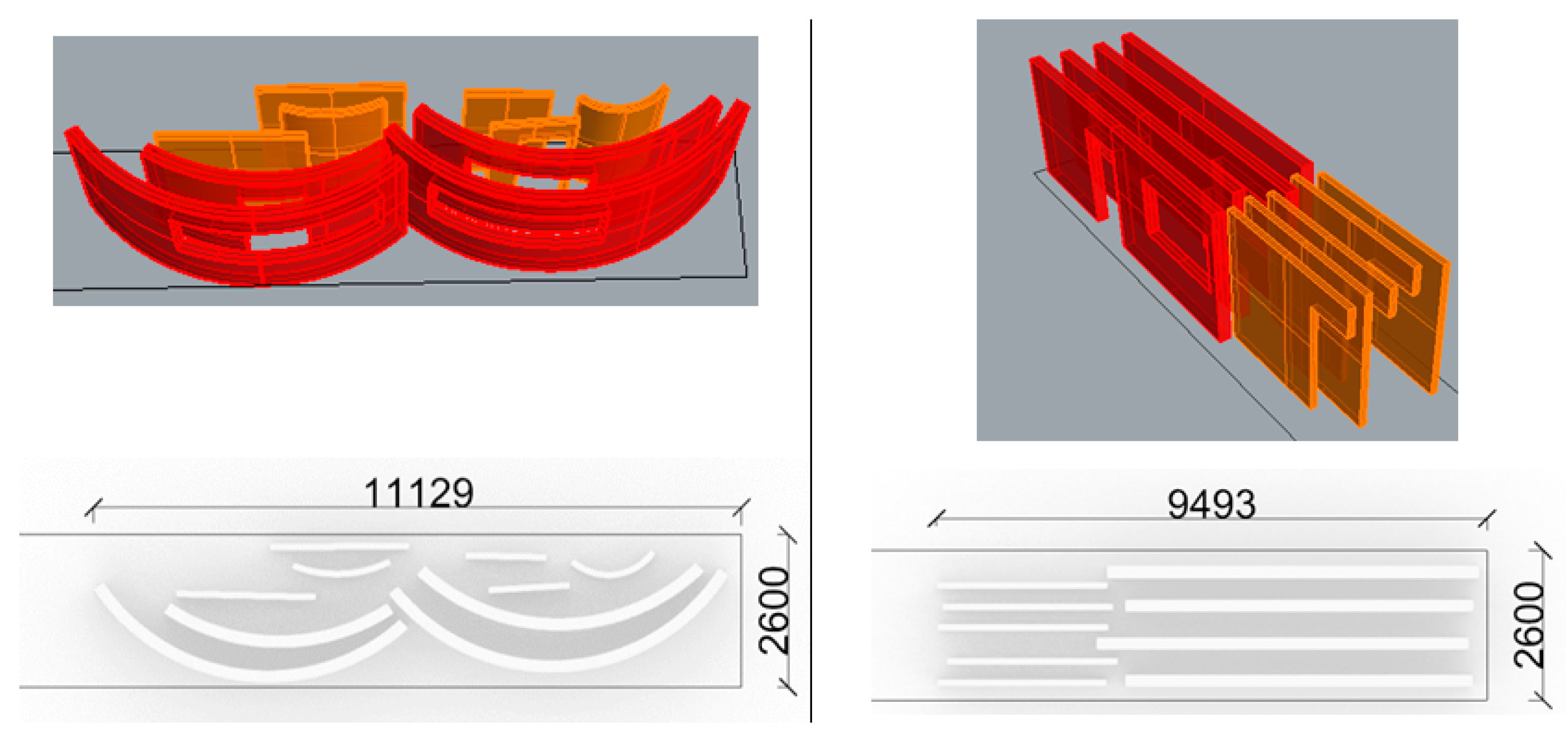
Figure 2 shows the simulation of the model and how the printed wall components could be transported for the off-site scenarios. These constraints were considered when calculating the transportation costs.
For the cost and time analysis, we used case data collected from two experimental uses of 3DCP in the real world (Singapore and Denmark) [44] and introduced expert opinion and analysis to create the cost models. For the analysis of conventional construction methods, we used data from Nordic countries, such as Swedish cost data from the International Construction Market Survey 2019 [49], Finnish construction work amount statistics (construction productivity information files, i.e., Ratu cards) [50], and sale prices from the largest material providers in Finland. The cost calculations were performed in euros, and costs were calculated for Nordic countries.
The cost model considered the following parameters: construction machinery and equipment, raw materials, transportation, and labor. Table 2 shows the details of the items used in the cost calculations. To examine each case from a time perspective, we utilized process mapping and calculated the time required for each step in the process map. The time analysis starting point was the moment at which the design was ready, and 100 houses were then printed.
In this research, robotic arm-based 3DCP was chosen over gantry-based 3DCP. The reason behind this choice is that due to the nature of the project regarding the high number of units and the size of the units which are single-story houses, robotic arm-based 3DCP allows for faster deployment (e.g., assembly and disassembly). A robotic arm-based 3DCP system can be moved in the construction site using a forklift and be installed for printing in less than an hour, and this is in contrast to gantry-based 3DCP systems, where the installation for printing requires about one day. This pattern also holds for the unmounting of the two systems.
A disadvantage of the robotic arm-based 3DCP system compared to the gantry-based 3DCP system is its limited reach [53] which requires mounting and unmounting of the robotic arm numerous times during the printing of a single house depending on the size of it. Therefore, this mouting and unmounting of the robotic arm can makes it less suitable for very large houses; however, in this project, the size of the houses does not require more than two movements of the robotic arm during the printing of each unit. As a result, the use of a robotic arm-based 3DCP system was preferable for the specific characteristics of the project in our study which are the size of the houses and the number of replications.
Moreover, the transportation of a robotic arm to a site is easier than the transportation of a gantry system. The robotic arm can be transported on one standard euro pallet (1200 × 800 mm), while a gantry requires a larger truck and crane for transportation and mounting. The robotic arm setup also requires only one or two workers to set it up, as opposed to the gantry system, which requires cranes and four to five workers.

4. Results

Our results cover the 3DCP process from time and cost perspectives for all seven scenarios. In Section 4.1, we report our findings related to the analysis of the scenarios’ process time maps, while in the subsequent Section 4.2, the results of analyzing the cost of scenarios are presented.

4.1. Process Time Analysis

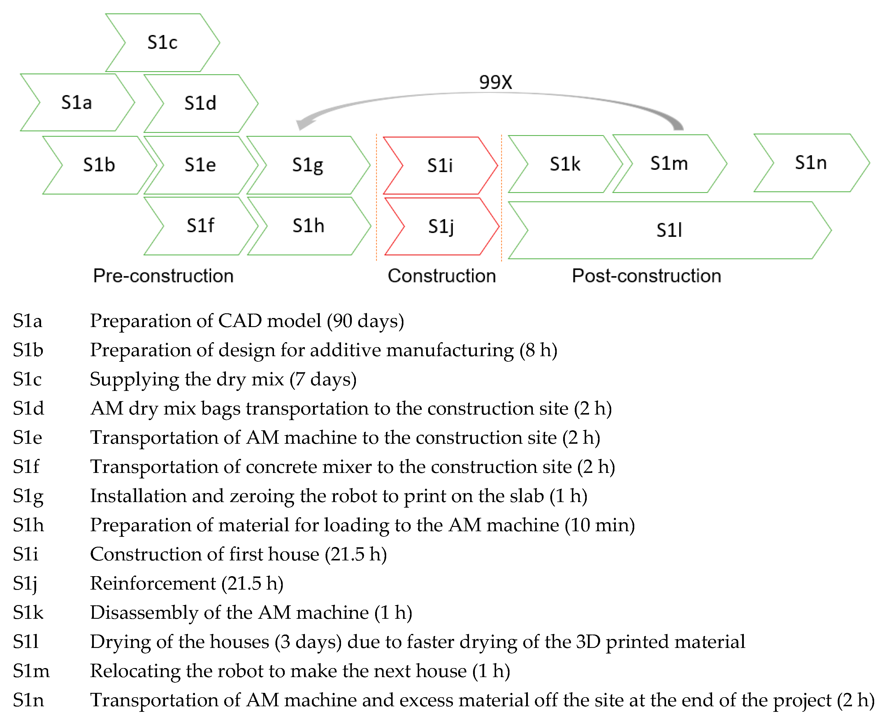
The Scenario 1 (S1) process starts with the preparation of the CAD design model and receiving the required approvals for the construction. This step could take up to 90 days. The next step after the design approval is the preparation of the design for additive manufacturing, during which the design is fine-tuned based on the specification of the printer selected for the project, and export of the design to the robot tool path generator. This step could take up to eight hours. The dry mix, which is the raw material for 3DCP, is then ordered and received by the company before being shipped to the project site. This step has a seven-day lead time. Thereafter, the dry mix, the robotic arm, and the concrete mixer are transported to the project site in approximately two hours. Once the robotic arm is on the site, it should be installed, calibrated at the first house construction location, and connected to a concrete pump attached to a mixer. The preparation of the robotic arm could take up to one hour. In the next step, the construction of the house walls starts, and the robotic arm lays the wet mix of concrete layer by layer according to the pre-determined path.
Reinforcement also takes place during the construction phase, which includes adding steel components for structural tension. The construction and reinforcement steps last for 21.5 h. Once the whole house is printed, the robot could be unmounted from the floor and relocated to the next site location, and the process is repeated until all the walls of 100 houses are completed (Figure 3). Printed house walls could take up to 72 h to dry and be ready for the next phase of construction. The estimated total time required for each S1 house construction step (excluding the material ordering, design, and approval steps) is 34.5 h.
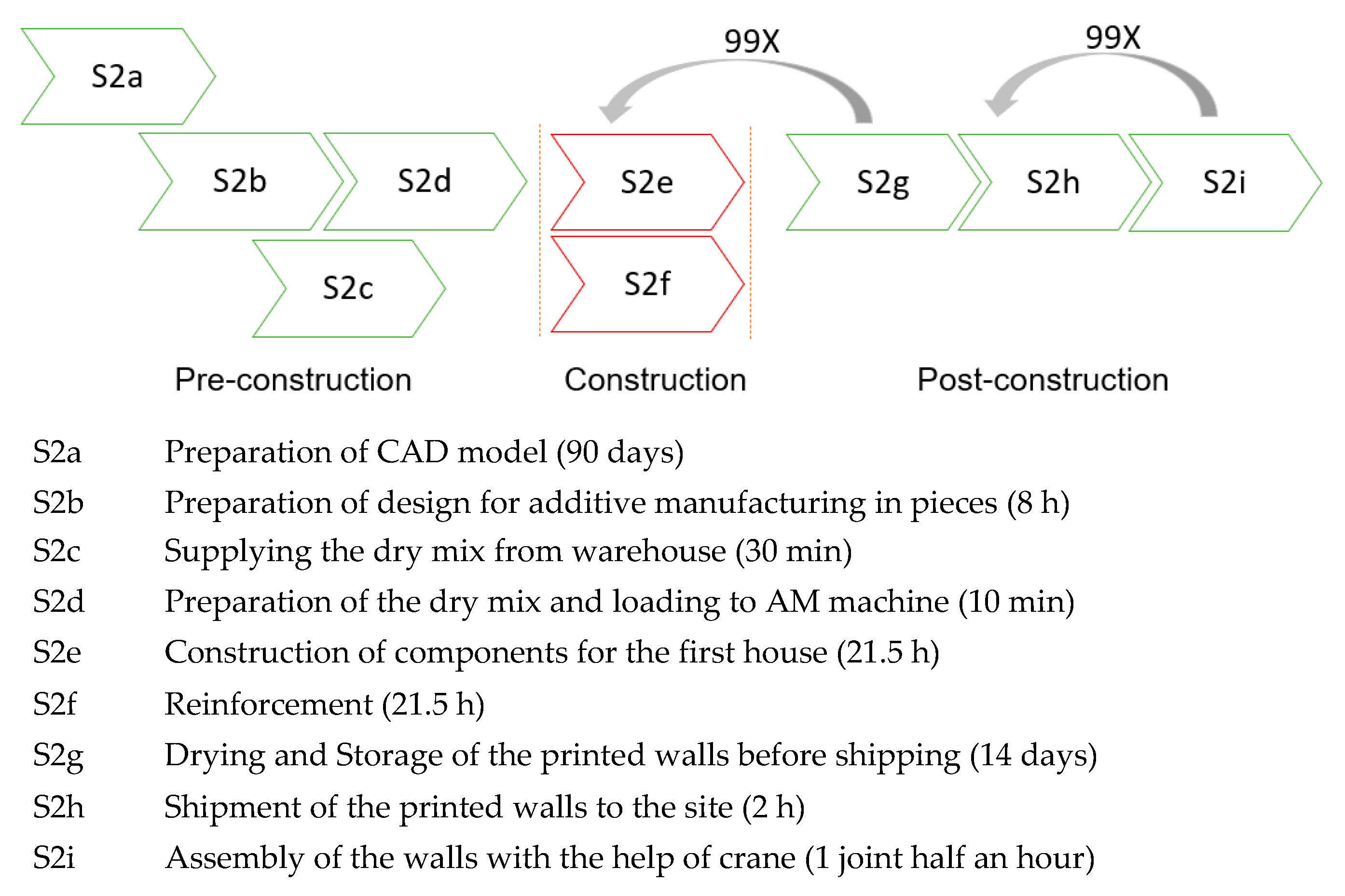
Scenario 2 (S2) starts with the design and approvals, and then the preparation of a design for modular production that could then be transferred to the construction site for assembly is performed. The preparation of the design also includes exporting the design to the robot tool path generator. This step takes approximately eight hours. The dry mix is retrieved from the inventory and is prepared in 10 min. Thereafter, the additive construction of the wall modules at the factory starts using robotic arms. The reinforcement of the modules takes place simultaneously with the 3DCP process. The additive construction and reinforcement steps take approximately 21.5 h to complete. The wall modules could go through a drying period of 14 days in storage before being shipped to the site. Transportation to the site is assumed to take two hours. On the site, the wall pieces should be assembled by the workers using a crane, which could take approximately five and a half hours. The process of construction, transportation, and assembly is repeated until the walls of all 100 houses are installed on the project site and ready for the remaining construction steps. The estimated total time required for the S2 construction steps (excluding the material ordering, design, and approval steps) is 15 days and 13.16 h (Figure 4). This is considerably longer than the S1 time due to the 14 days required for the walls to dry before they could be transported to the project site. If the delay caused by the concrete drying is excluded from S2, the process for each house only takes 37.16 h.
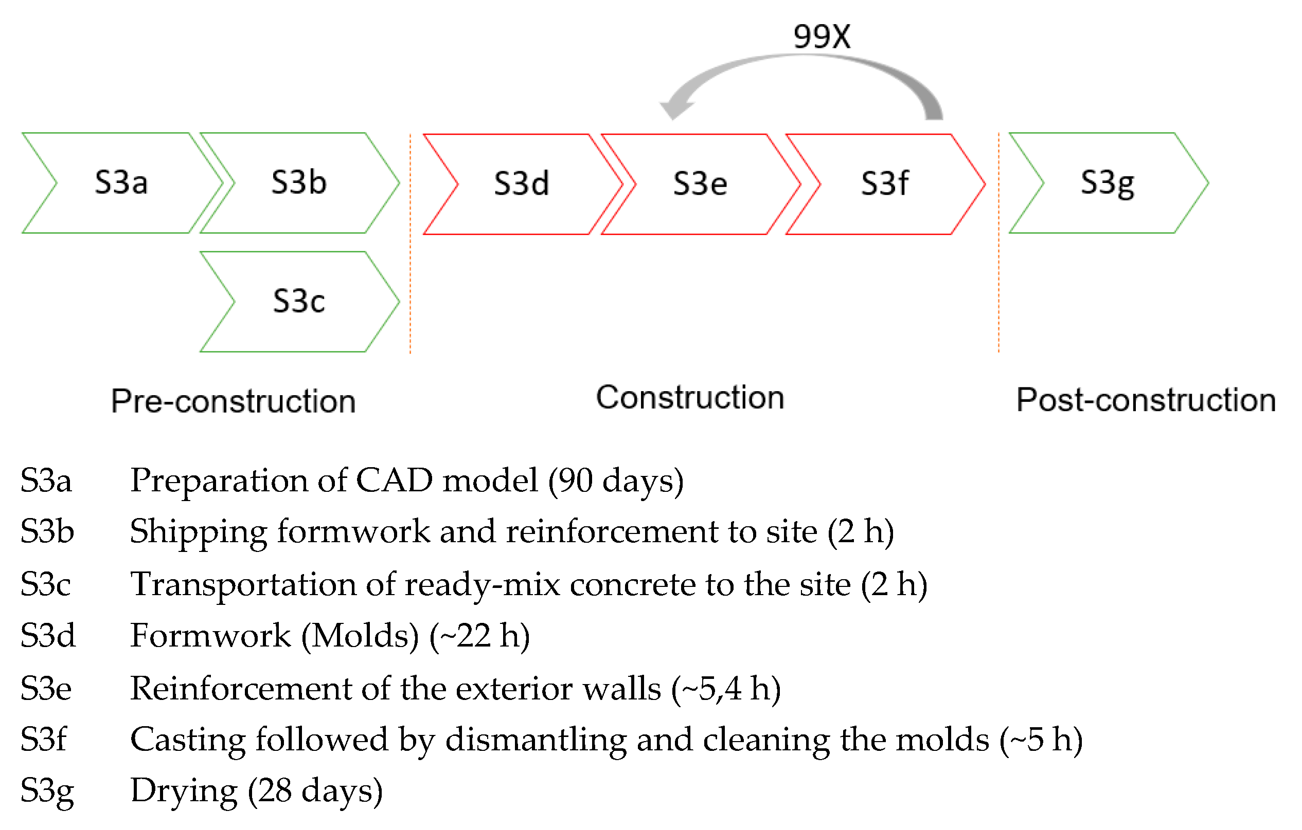
For the round houses in Scenario 3 (S3), the proper conventional construction method is cast-in-place concrete. The process map for S3 is presented in Figure 5. In this process, after the CAD design, the first task is to ship the formwork to the construction site. Formwork includes setting up molds for both the external and internal walls. For curved walls, this should typically be carried out using timber. After formwork, exterior walls must be reinforced with steel according to recognized construction codes. Ready-mixed concrete is then transported from the factory to the site and cast from the truck into the molds. After the required hardening time, molds are finally dismantled and cleaned. Mold material can often be recycled and utilized in subsequent formwork. The 44 h for the formwork includes the dismantling and cleaning steps. Two workers are used for the on-site operations. It takes 28 days for the concrete to reach its nominal strength. Since houses would be built immediately after each other, the drying time for the concrete in conventional scenarios is calculated only once to build 100 houses. The process of building one house takes approximately 1.5 days. The build process time of S3 is 29 days and 12.4 h when including the drying time for conventionally built houses which makes 3DCP scenarios faster than S3.
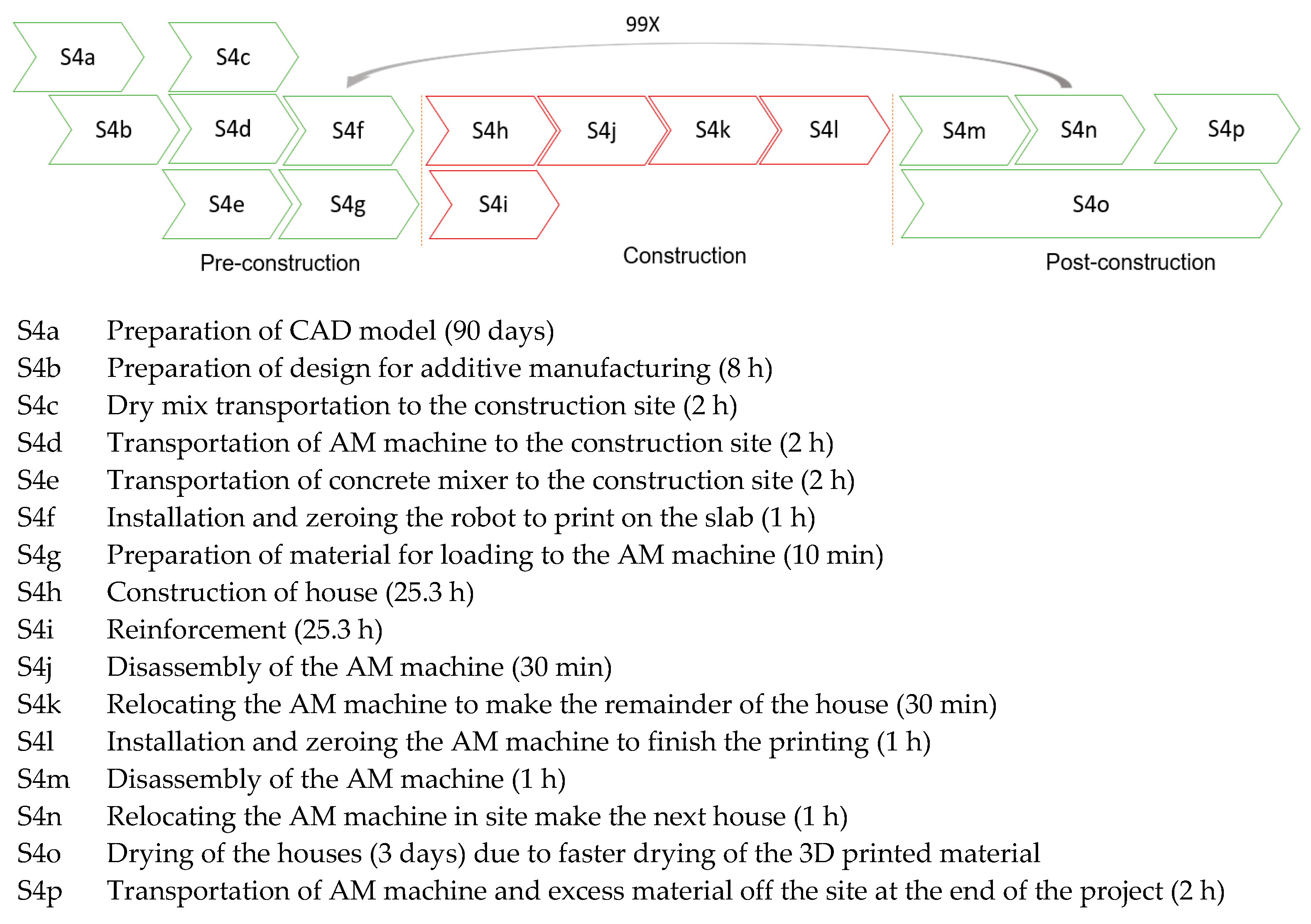
The process for Scenario 4 (S4) is presented in Figure 6. It is similar to S1, with two main differences. The first difference is due to the reach of the robot arm and the size of the house. The robot has to be mounted in two separate locations, and the printing process has to be carried out in two stages. This adds approximately two hours to the construction process. The second difference between S4 and S1 arises from the shape of the house, which results in construction time differences. The time taken for printing and reinforcement for S4 is 25.3 h. The total process time for S4 is 110.3 h (about 4 days and 14 and a half hours), which is only 5.5% longer than for S1. This illustrates the positive impact of the round design on the process time of 3DCP.
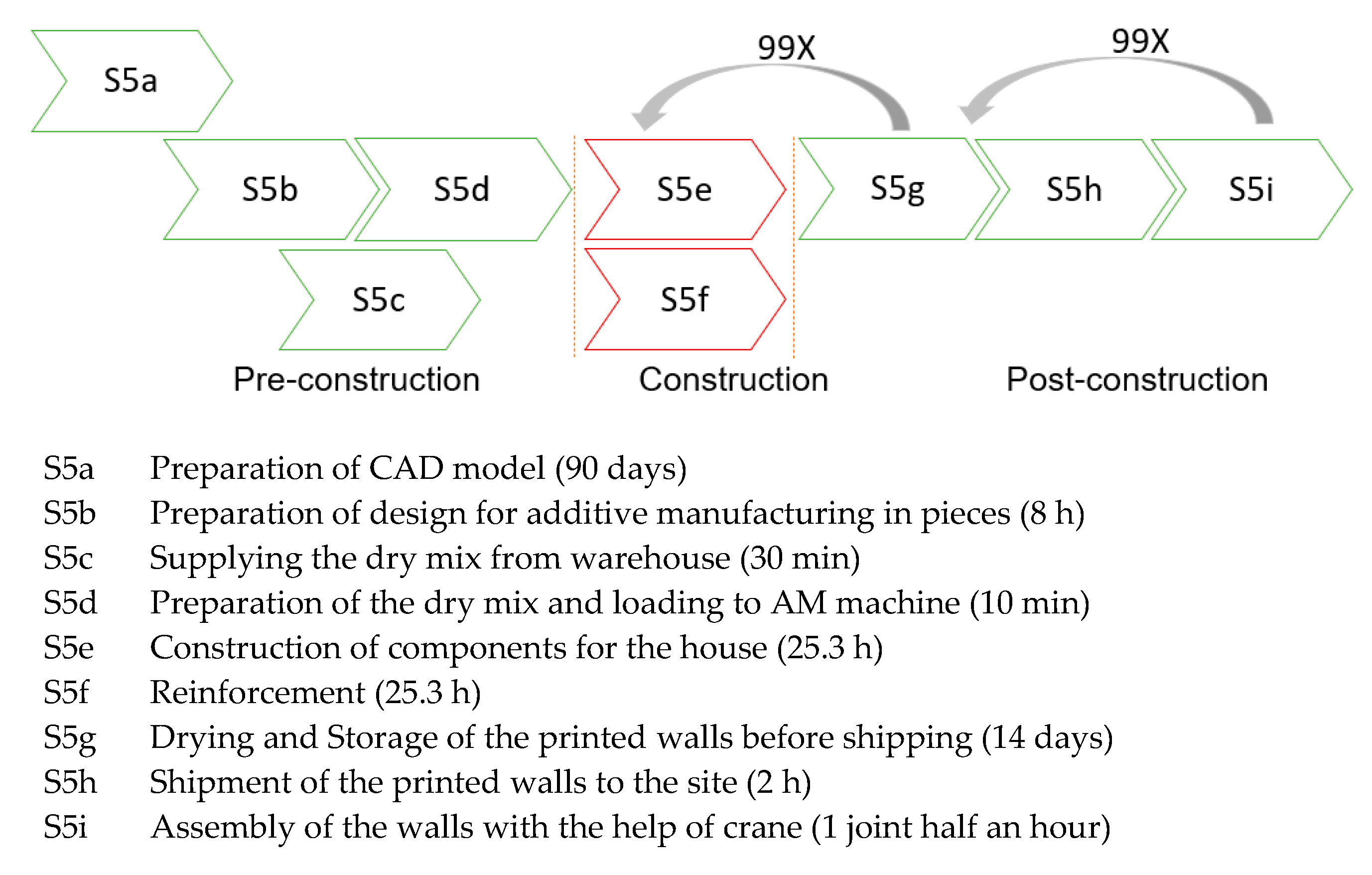
Figure 7 illustrates the process map for Scenario 5 (S5). The construction process is similar to that for S2, with one difference relating to the design of the house, which results in distinct construction and assembly times. The construction and reinforcement time for S5 is approximately 25.3 h. Moreover, for the rectangular design in S5, 11 joints require assembly, which results in an extra five and a half hours, based on the assumption of half an hour per joint assembly. The total process time for S5 is 15 days and 16.96 h, which is approximately 240% longer than for S4. The main reason for this significant difference is the 14 days required to dry the off-site printed modules.
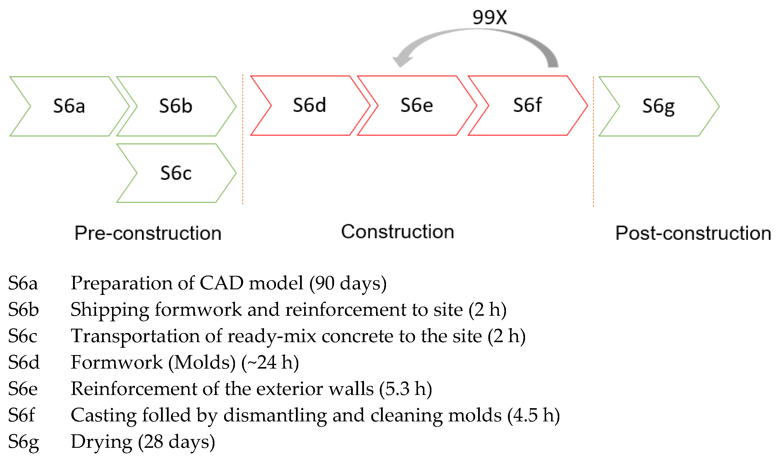
The process for Scenario 6 (S6) is depicted in Figure 8. It entails designing the house model, transporting the formwork and reinforcement materials to the site, the formwork, the reinforcement, transporting concrete to the site, and dismantling and cleaning the molds ready for reuse, as well as the drying time of the concrete. In such a project, there is an option to order premanufactured molds. In S6, we assumed that the formwork is also conducted in the conventional way. The 49 h used for formwork includes dismantling and cleaning the molds. Transportation of the ready-mixed concrete is assumed to be simultaneous with the other pre-construction steps. The process for S6 is similar to that for S3, with only one difference related to the shape of the house. The most time-consuming step in the S6 process is reinforcement, apart from the 28 days of the concrete drying time. We assume that two workers handled the site operations. The total process time for S6 is 29 days and 13.8 h per house including the drying time of the concrete. Processes in 3DCP scenarios are faster than those in S6.
The Scenario 7 (S7) process map is presented in Figure 9. The time estimation for S7 is not fully comparable with the other scenarios since the data represent the sourcing of the prefabricated modules from a third-party supplier. The process starts with the design phase and obtaining the component configurations for the design. The precast concrete elements are ordered from the element factories; they are produced there and shipped to the site. The factories expect orders to be placed six months before project kick-off due to their manufacturing capacity and allocation of orders. This lead time only happens once at the beginning of the process. After the delivery, the elements are installed using a crane and on-site workers, and the joint concrete work is then completed. The rate of work consumption is based on Finnish construction productivity information Ratu cards, and it takes 0.19 h per concrete element per square meter to install.
Table 3 illustrates the schedule comparison of all scenarios. We divide the whole construction process into three main stages: pre-construction, construction, and post-construction. The pre-construction in 3DCP scenarios involves all the steps that need to be taken after the architectural design is ready, from the construction permissions being received from the authorities to initiation of the actual construction of the building. For the on-site conventional scenarios, pre-construction involves shipping the required steel, timber, and ready-mixed concrete. For the S7 prefabrication scenario, pre-construction involves extracting the concrete component configurations from the design model and the ordering, manufacturing, and shipping time for these components.
The construction stage in the 3DCP scenarios includes the steps relating to the printing of the walls and the reinforcement stages of the 3DCP process until the printing is completed. For the on-site conventional scenarios, the construction involves formwork, reinforcement, concrete casting, and demolding and cleaning the molds. For S7—the prefabrication scenario—construction involves the assembly of concrete wall components and joint concrete work.
The post-construction stage in 3DCP scenarios includes disassembly and relocation of the printer, drying of the off-site printed wall, transportation to the site, and assembly of the wall modules. For the on-site conventional scenarios, the only post-construction activity is the drying of the concrete, which can be excluded from estimating the time taken to build 100 houses consecutively. For the S7 prefabrication scenario, post-construction involves the drying time of the joint concrete, which is estimated as one day.
As can be seen from Table 3, off-site 3DCP requires more time for the whole process due to the longer post-construction phase.

4.2. Cost Analysis

For the off-site scenarios, we used a two-axle truck with 16.2-ton capacity for the transportation of the printed components. Table 4 illustrates the required means of transportation. The cost of the labor was assumed to be EUR 42 per hour. A two-axle truck was rented for two full days for transportation of the printing robot. For the transportation of the robot around the site during the printing process, we assumed the use of a forklift. Detailed cost information for the scenarios can be found in Appendix B.

4.2.1. Scenario 1

The S1 or ONP-RND scenario included the on-site concrete printing of the round design. In S1, we used a robotic arm and the dry mix shipped to the construction site to build the walls of the house (the base floor slab and the roof were not part of our modeling and calculations). There were four main cost components in S1: robot, material, labor, and transportation costs. For this research, where the scope of the construction project was 100 identical houses, we assumed the use of five robotic arms to reduce the overall project completion time by executing parallel production. In S1, due to the round shape of the design, the print job could be performed with no movement of the robotic arm during the construction of each house, due to the sufficient reach of the robotic arm. In S1, like the other scenarios, we used a two-axle truck for the transportation of the materials and the robotic arm, and a forklift to move the robotic arm from one completed house to the next.
Our calculations illustrated that 55.6% of the wall construction costs related to labor costs, while 30.4% of the costs related to the materials used for the printing, reinforcement, and waste. Transportation and robot costs were responsible for 11.1% and 2.9% of the total wall construction costs in this project, respectively. This illustrated that, although the process took advantage of robotic automation, the monitoring and management of the robot still entailed costs for a significant amount of manual and skilled work. For more detail refer to Table A2.

4.2.2. Scenario 2

The S2 or OFP-RND scenario included the use of concrete printing for off-site construction of a round house. S2 was comparable to S1 and only differed in the way the production of parts was carried out off-site. The four cost components for this scenario were labor, material, machinery, and transportation costs, representing 42.4%, 20.7%, 20.1%, and 16.9% of the total cost, respectively. While the cost of transportation for this scenario, as expected, was higher than for S1, the machinery cost was significantly higher than for S1 due to the need for a crane to assemble the wall modules. As a result, the total cost for S2 was 47% higher than that for S1. This was also partly due to the extra labor cost for the wall module assembly. For more detail refer to Table A3.

4.2.3. Scenario 3

For the S3 or ONC-RND scenario, timber plank boards were used for the formwork, and the work included dismantling and cleaning the molds, which were included in the rate. The rate for the molds for the external walls was higher than the rate used for S6 due to the circular house model. The cost of the concrete included 4% waste. The transportation of the materials to the site corresponded to 7.8% of the total cost. Material costs represented 43.4% of the total cost, while the labor cost was 48.8%. For more detail refer to Table A4.

4.2.4. Scenario 4

The S4 or ONP-RECT scenario used concrete printing for the on-site construction of a rectangular house. S4 only differed from S1 in its geometric design, while the area inside both houses was comparable at 40.69 m2. In S4, like S1, we had four main cost components, and the share of each cost component in the total cost was 52.9% for the labor, while material, transportation, and robot costs accounted for 34.1%, 10.2%, and 2.7%, respectively. Interestingly, the cost for S4 was 26.8% higher than the cost for S1. This was due to the design of the houses, since the conventional design required more raw materials, a longer construction time, and movement of the robot during the construction of each house. This suggests that taking advantage of AM design to enhance performance also allows for construction cost savings. For more detail refer to Table A5.

4.2.5. Scenario 5

The S5 or OFP-RECT scenario used 3DCP for off-site construction of identical rectangular houses. S5 was like S4, only differing from it in the way the houses were constructed off-site. The cost components for S5 were labor, material, machinery, and transportation costs, representing 41.6%, 25.3%, 17.5%, and 15.6% of the total cost, respectively. S5 was 35.2% more expensive than S4 because of the higher machinery and transportation costs and the slightly higher labor costs. This finding suggests that 3DCP is more cost-efficient when performed on-site for large projects such as the one studied for this article. When comparing S5 with S1, we found that S5 was 71.4% more expensive per constructed unit. This proved the cost savings from the use of AM design, which enables houses to be manufactured on-site with less labor and less equipment required for transportation and assembly. For more detail refer to Table A6.

4.2.6. Scenario 6

The S6 or ONC-RECT scenario modeled the on-site rectangular house construction. It differed from S3 only in the shape of the house. The rates were the same as those for S3, except for the labor cost for mold work, which was less due to the rectangular shape of S6. Transportation costs comprised 9.1% of the total cost of building a rectangular house on site in a traditional way. Labor costs corresponded to 36.8%, while material costs constituted 54.1% of the total cost. The cost for S3 was 3.2% greater than the cost for S6 due to the more complex and costly molding of the round house. The material cost for S6 was higher than the material cost for S3 because the surface area of the rectangular house model was larger than the surface area of the circular house model. The rates used for calculation of material costs were per square meter. For more detail refer to Table A7.

4.2.7. Scenario 7

The S7 or OFC-RECT scenario considered off-site construction of rectangular house modules—also known as prefabrication. This scenario was important since the efficiency of this method for conventional house designs is well known. However, the numbers relating to the costs for this scenario were collected from the end customer and therefore included a profit margin. The cost data were obtained from several Finnish concrete element factories. External walls cost EUR 140 per square meter, and internal walls cost EUR 90 per square meter. Thus, these numbers were only used for the purpose of rough comparison with the other scenarios, which excluded the profit margins. If we conducted an estimate by excluding a 30% profit margin from S7, the cost was around EUR 9000, making it comparable to conventional scenarios S3 and S6.
The most significant cost component was the concrete element cost. The labor cost for S7 was naturally lower than for S3 and S6, since prefabrication is less labor-intensive than conventional construction methods. The crane used to lift and move the components to be assembled to the assembly location comprised 6.3% of total costs as a machinery cost. The daily cost of renting a truck and its driver was taken as EUR 500 for all the off-site scenarios. The transportation cost was about 4% of the total cost in this scenario. For more detail refer to Table A8.

4.2.8. Summary of the Cost Analysis

Table 5 presents the cost components for all seven investigated scenarios. It is interesting that the cost of S3 was about 135% higher than that of S1, suggesting that 3DCP is more cost-efficient for the wall construction of round houses. This cost saving was due to eliminating the formwork via 3DCP [55]. Comparing the cost of S4 and S6, we observed a 80.1% cost disadvantage for on-site traditional construction of a rectangular house, illustrating the dependence of the cost advantage for each construction technology on the design. While 3DCP was more cost-efficient for both the round and rectangular designs, this cost advantage eroded when the rectangular design was chosen because it was mold-friendly and less suitable for the size of the AM robot, which needed to be relocated during the process to complete the task. In the conventional scenario calculations, the multipliers also included the cost of the machinery; hence, there is no separate machinery cost in Table 5 for the conventional construction scenarios.
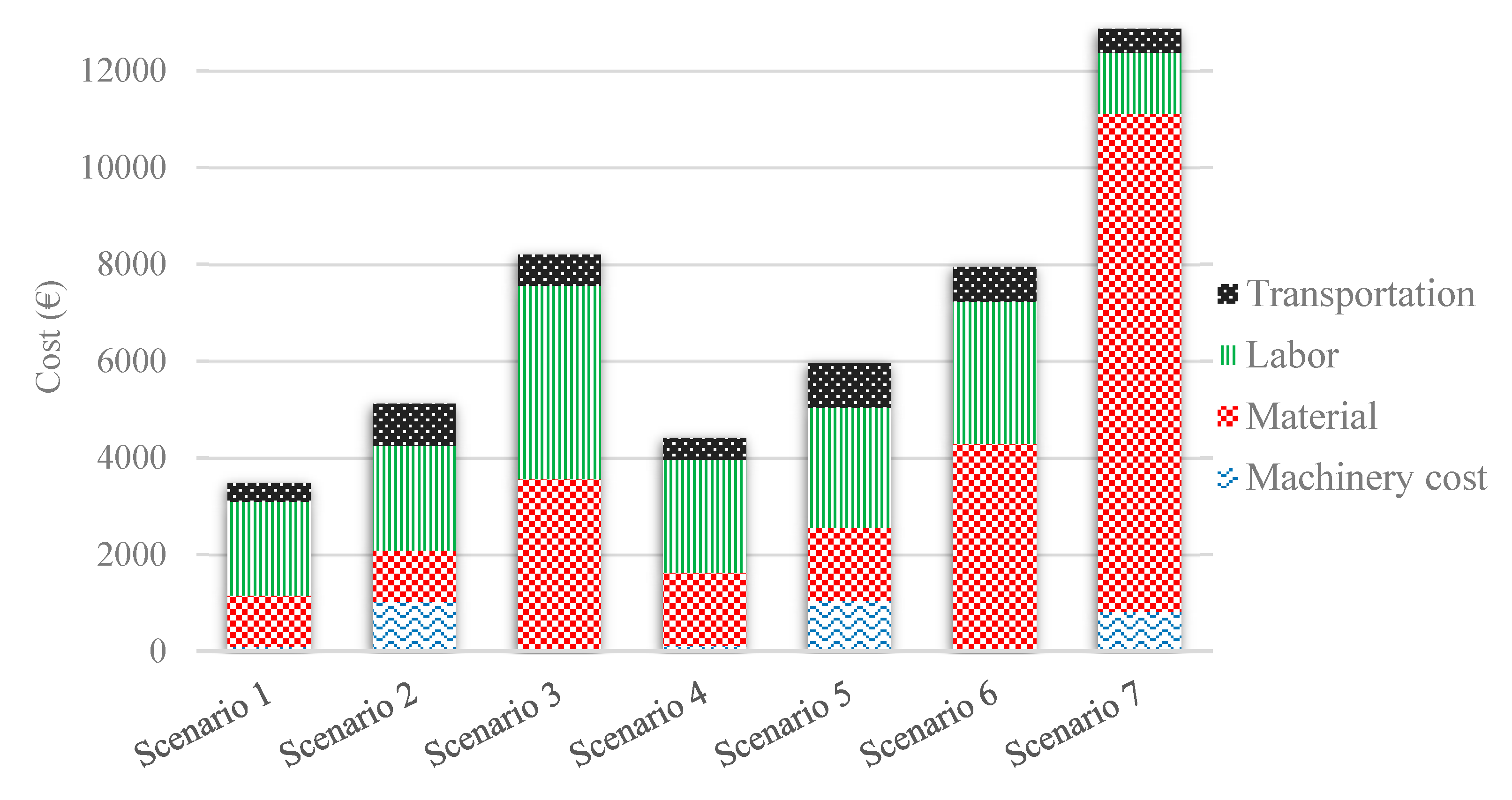
Figure 10 illustrates the cost percentages for each scenario based on machinery, material, labor, and transportation costs.

5. Discussion

The construction industry is one of the least automated industries, and its productivity has been stagnant until recently, but digital transformation due to the emergence of new tools such as 3DCP promises to change the status quo [4]. In this research, we investigated the time and cost impacts of 3DCP compared to conventional construction methods using multiple different design and supply chain options. The analysis revealed that 3DCP provides opportunities to execute complex designs without additional costs. Concrete printing allows for multi-purpose construction design, meaning that with the advantage of complex geometries enabled by 3DCP, a wall can be designed and constructed in a way that makes it not only a space separator but also an insulator, due to its internal shape.
In our study, 3DCP allowed for the construction of geometrically complex designs with significantly lower costs compared to conventional methods. We illustrated that the construction of a round house costs less using 3DCP than when using traditional construction methods. This was in line with the literature, which found that a 3D-printed model cost less than a model constructed using traditional construction methods [11]. Moreover, unlike conventional construction methods, the cost of constructing a round house with 3DCP was less than the cost for a rectangular design. This was due to the need for more materials and a larger printing volume in the case of the rectangular design. In terms of schedules, our analysis illustrated that 3DCP was advantageous compared to the conventional and prefabrication construction methods, especially when the concrete drying times were considered in the calculations.
Another interesting point is that concrete printing still requires a significant amount of labor for the management, running, movement, calibration, and alignment of the robot and the other subsystems for successful construction. The operator needs to be on-site monitoring the printing operations, which is a high-end technology-based job [56] requiring extensive training. Thus, this area can benefit from further automation to potentially decrease labor intensity and increase 3DCP’s competitiveness.
The construction industry is highly regulated, and this is one of the reasons why 3DCP has not yet significantly disrupted this industry. Different countries, states, and provinces have their own construction standards. Approval processes also vary depending on the geographic location. The use of 3DCP in construction is not yet included in the current standards [57], and this poses challenges in terms of regulatory approvals. Most of the building codes and procurement standards do not consider 3DCP technology [58]; thus, 3DCP companies follow generic, already established construction standards in their respective locations. This makes the 3DCP construction approval process longer than that for traditional construction methods. Currently, structural tests are being conducted, and technical recommendations will eventually be made based on such empirical findings [59]. Other 3D printing methods already have established standards, and 3DCP is now moving in the direction of similar standards. In the 3DCP field, a global effort is underway to establish new draft standards, such as the 3DCP Standard (ISO/ASTM 529XX PWI Additive Manufacturing for Construction—Qualification Principles—structural and infrastructure) [60]. Many stakeholders including material manufacturing companies, construction companies, and 3D printing companies are working together to develop standards for 3DCP. Such standardization can facilitate regulation and streamline the acquisition of construction permits for additively manufactured houses.
As the results of our study on constructing 100 similar houses show, producing a structure directly from a digital design model allows the same design model to be used repeatedly in a project or even consecutively in other projects. This provides opportunities for efficiency inherent in the utilization of AM for construction aligned with the direct digital construction concept [61]. Thus, 3D concrete printing applications for construction are a step toward industrial construction.

6. Conclusions

The construction industry, which is among the industries with the least amount of digitalization, can significantly benefit from digitalized solutions. The 3DCP technology is one of the digitalization methods that has notable implications for construction efficiency. In this research, we calculated the cost and completion time differences for a housing construction project using different methods, supply chain configurations, and designs. We excluded the parts of the process maps that were identical for all scenarios, such as the foundation slab work, roofing, painting, and tiling. This research illustrated that 3DCP is both time- and cost-competitive with on-site conventional construction. More specifically, we found that the cost of on-site conventional construction methods for round houses is more than two times higher than that of on-site 3DCP for the same design. This suggests that 3DCP is more cost-efficient for the construction of round walls. Similarly, while comparing the cost of the on-site conventional construction method for the rectangular design and on-site 3DCP for the same design, we observed a 80.1% higher cost for the on-site conventional construction method. The cost efficiency of 3DCP was related to the lack of formwork, which reduced the material costs significantly and also decreased the cost of labor. We also found that, although complex design proved to be costly for conventional construction, for 3DCP, it had positive effects on the efficiency and process time.
On-site 3DCP proved to be significantly more time-efficient than the other scenarios due to the elimination of assembly work and the fact that drying could take place on-site while other activities were being performed concurrently. This is interesting since prefabrication is known to be cost-effective and time-efficient, but 3DCP proved to be a worthy competitor.
The contributions of this research are threefold:
  • The cost and time competitiveness of conventional construction methods versus 3DCP was evaluated;
  • The impact of the design on the cost and time efficiency of 3DCP was analyzed;
  • The impact of supply chain configurations (off-site versus on-site construction) on the cost and process time competitiveness of 3DCP was uncovered.
This research was limited to investigating the effects of house design variations. Moreover, we did not study gantry-based 3DCP. Future research must focus on case studies of real-world designs, cost and schedule comparisons for different 3DCP methods, and comparisons with a wider range of traditional construction methods.

Author Contributions

Conceptualization, S.H.K., Y.W. and M.L.; methodology, S.H.K., J.H., M.T., A.M. and A.P.; software, A.M.; validation, S.K, A.M., M.T. and A.P.; formal analysis, S.H.K., M.T., and A.P.; investigation, S.H.K., Y.W., J.H., M.T., A.M., A.P. and M.L.; resources, A.M.; data curation, S.H.K.; writing—original draft preparation, S.H.K., M.T., A.M. and A.P.; writing—review and editing, S.H.K., Y.W., J.H., M.T., A.M., A.P. and M.L.; visualization, A.M.; supervision, S.H.K.; funding acquisition, J.H. and A.P. All authors have read and agreed to the published version of the manuscript.

Funding

This research was funded by ACADEMY OF FINLAND, grant number 323831.

Institutional Review Board Statement

Not applicable.

Informed Consent Statement

Not applicable.

Conflicts of Interest

The authors declare no conflict of interest. The funders had no role in the design of the study; in the collection, analyses, or interpretation of data; in the writing of the manuscript, or in the decision to publish the results.

Appendix A

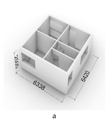
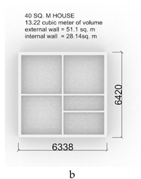
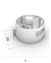
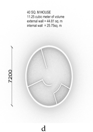
Table A1. The architectural 3D model of the cases.
3D ViewTop View
Rectangular house and its internal and external walls Applsci 11 03865 i001 Applsci 11 03865 i002
Round house and its internal and external walls Applsci 11 03865 i003 Applsci 11 03865 i004
The buildings’ dimensions and specification:
The thickness of external walls is 230 mm and the thickness of internal walls is 110 mm.
The height of the walls is 2.5 m. The density of walls made by 3DCP in this research is assumed to be 40%.
Material used for 3DCP and its difference with the concrete used for conventional construction:
The concrete used in the conventional construction includes cement, sand, water, and aggregate. The concrete mix that is used for 3DCP has no aggregate, but it includes a chemical mix (also known as admixture) consisting of a plasticizer and accelerant. The plasticizer regulates the flowability of the concrete so that it can be pumped and laid down using the printer nozzle, while the accelerant increases the solidification rate of the 3DCP concrete so that the concrete layers can be printed on top of one another without the need for long pauses. Due to these differences, the costs of conventional concrete and 3DCP concrete are different. In our case, the cost of 3DCP concrete per cubic meter is EUR 150, while the cost of conventional concrete per cubic meter is EUR 110.
Technical specification of the 3DCP machine and the process:
The robotic arm used for this study is a Kuka KR120 R3900 six-axis with a radial maximum reach of 3901 mm and a weight of approximately 1.2 tons. It is rated for 120 kg payloads [51]. The printer used in this study has a nozzle dimeter of 30 mm and can lay down 200 mm length of concrete at a layer thickness of 12 mm. In our printing time calculations, we used a safety factor of 1.25.

Appendix B

In all the AM scenarios (S1, S2, S4, and S5), hallow walls with a density of about 40% are used which allows for a reduction in the amount of material required for the construction compared to the conventional construction scenarios (S3 and S6).
Table A2. Scenario 1 cost model in detail.
ItemCost componentQtyUnitRate (€)Cost
1Machinery
aHour of usage of 3DCP *21.5h€ 4.11€ 88.48
bMaintaince of 3D concrete printer € 0.55€ 11.8
Section Total € 100.27
2Material
aConcrete11.25€ 150€ 669.64
bWaste5 % € 33.48
cLintel (windows and doors)4pc.€ 80€ 320
dReinforcement5 % € 33.48
Section Total € 1056.61
3Labor
aMachine set up2h€ 42€ 84
bLabor cost of operator of robot2pers.43.06€ 1808.45
cLabor for in-site transport1h€ 42€ 42
Section Total € 1934.45
4Transportation
aRobot: In the begining and at the end of the project with 2-axle truck (includes the daily driver fee)€ 1 0002€ 20
bRobot: Before and after the print job with forklift€ 116.671€ 1.17
cRobot: During the print with forklift€ 2.330€ -
dMaterial **€ 1000 € 365
Section Total € 386.17
Total cost for one building € 3477.5
* Acquisition of robotic arm, concrete pump, and mixer. ** Dry mix transportation to the site with 2-axle 16.2-ton truck. We assume that in one day, two trips to the site and back are possible. The cost also includes the daily driver fee. Note: base floor slab is 130 mm thick and is the same for all the scenarios.
Table A3. Scenario 2 cost model in detail.
ItemCost componentQtyUnitRate (€)Cost
1Machinery
aHour of usage of 3DCP *21.5h€ 4.11€ 88.48
bMaintaince of 3D concrete printer € 0.55€ 11.8
cOffloading the pre-constructed walls and installation of walls at the site using a 50 tonnes crane **€ 1 139 € 925.44
Section Total € 1025.71
2Material
aDry mix bought in powder form11.25€ 150€ 669.64
bWaste5 % € 33.48
cLintel (windows and doors)4pc.€ 80€ 320
dReinforcement5 % € 33.48
Section Total € 1056.61
3Labor
aMachine set up0h--
bLabor for moving the parts to the storage for drying1 € 42€ 42
cLabor cost of operator of robot2pers.€ 43.06€ 1808.45
dLoading at the factory and offloading at the site2h€ 42€ 84
eAssembly of the walls in the site0.5h€ 42€ 231
Section Total € 2165.45
4Transportation
aPre-constructed items: Transportation of walls to the site using 2-axle truck ***€ 1000 € 500
bMaterial ****€ 100073€ 365
Section total € 865
Total cost for one building € 5112.77
* Cost of 3DCP includes the acquisition of robotic arm, concrete pump, and mixer. Moreover, we assume that the time for printing the walls in pieces is the same as the print in one piece. ** Including the driver. Additionally, assuming one hour for offloading and five and a half hours for assembly. *** Maximum 16.2-ton and 12 × 2.6 m trailer dimensions (the cost also includes the daily driver fee, assuming that we can perform 2 trips to the site per day). **** Transportation of dry mix to the factory on 16.2-ton truck in powder form, assuming that two trips to the factory are possible per day.
Table A4. Scenario 3 cost model in detail.
ItemCost componentQtyUnitRate (€)Cost
1Material
aConcrete including 4% waste, for external walls44.8m2€ 26.31€ 1 178.69
bConcrete including 4% waste, for interior walls25.75m2€ 12.58€ 323.94
cLintel4pc.€ 80€ 320
dReinforcement44.8m2€ 11.94€ 534.91
eTimber for extrnal and internal walls70.55m2€ 17€ 1199.35
Section Total € 3556.89
2Labor
aFormwork for external walls44.8m2€ 62.50€ 2800
bFormwork for internal walls25.75m2€ 31.25€ 804.69
cReinforcement44.8m2€ 4.45€ 199.36
dCasting concrete for external walls44.8m2€ 3.444€ 154.29
eCastong concrete for internal walls25.75m2€ 1.647€ 42.41
Section Total € 4000.75
3Transportation
aPump car for external walls44.8m2€ 11.07€ 495.94
bPump car for interior walls25.75m2€ 5.168€ 133.08
cSteel *44.8house€ 10€ 10
dTimber70.55house€ 0.5€ 0.5
Section Total € 639.52
Total cost for one building € 8197.16
* Transportation of steel to the site using 2-axle truck (max 16.2 ton and 12 × 2.6 m, includes the daily driver fee, assuming that we can performs 2 trips to the site per day).
Table A5. Scenario 4 cost model in detail.
ItemCost componentQtyUnitRate (€)Cost
1Machinery
aHour of usage of 3DCP *25.3h€ 4.11€ 103.97
bMaintaince of 3D concrete printer € 0.55€ 13.86
Section Total € 117.83
2Material
aConcrete13.22€ 150€ 786.9
bWaste5 % € 39.35
cLintel (windows and doors)8pc.€ 80€ 640
dReinforcement5 % € 39.35
Section Total € 1505.6
3Labor
aMachine set up3.5h€ 42€ 147
bLabor cost of operator of robot2pers.50.6€ 2125.13
cLabor for during the print transport0.5pers.€ 42€ 21
dLabor for in-site transport1h€ 42€ 42
Section Total € 2335.13
4Transportation
aRobot: In the begining and at the end of the project (includes the daily driver fee)€ 1 0002€ 20
bRobot: Before and after the print job € 116.671€ 1.17
cRobot: During the print only relocation€ 116.670.5€ 0.58
dMaterial **€ 1000 € 430
Section Total € 451.75
Total cost for one building € 4410.31
* Acquisition of robotic arm, concrete pump, and mixer. ** Dry mix transportation to the site with 2-axle 16.2-ton truck. We assume that in one day, two trips to the site and back are possible. The cost also includes the daily driver fee.
Table A6. Scenario 5 cost model in detail.
ItemCost componentQtyUnitRate (€)Cost
1Machinery
aHour of usage of 3DCP *25.3h€ 4.11€ 103.97
bMaintaince of 3D concrete printer € 0.55€ 13.86
cOffloading the pre-constructed walls and installation of walls at the site using a 50 tonnes crane **€ 1 139 € 925.44
Section Total € 1043.27
2Material
aDry mix bought in powder form13.22€ 150€ 786.9
bWaste5 % € 39.35
cLintel (windows and doors)8pc.€ 80€ 640
dReinforcement5 % € 39.35
Section Total € 1505.6
3Labor
aMachine set up0h--
bLabor for moving the parts to the storage for drying1h€ 42€ 42
cLabor cost of operator of robot2pers.€ 50.6€ 2 125.13
dLoading at the factory and offloading at the site2h€ 42€ 84
eAssembly of the walls in the site0.5h€ 42€ 231
Section Total € 2482.13
4Transportation
aPre-constructed items: Transportation of walls to the site using 2-axle truck ***€ 1000 € 500
bMaterial ****€ 100086€ 430
Section total € 930
Total cost for one building € 5960.99
* Cost of 3DCP includes the acquisition of robotic arm, concrete pump, and mixer. Moreover, we assume that the time for printing the walls in pieces is the same as the print in one piece. ** Including the driver. Additionally, assuming one hour for offloading and five and a half hours for assembly. *** Maximum 16.2-ton and 12 × 2.6 m trailer dimensions (the cost also includes the daily driver fee, assuming that we can perform 2 trips to the site per day). **** Transportation of dry mix to the factory on 16.2-ton truck in powder form, assuming that two trips to the factory are possible per day.
Table A7. Scenario 6 cost model in detail.
ItemCost componentQtyUnitRate (€)Cost
1Material
aConcrete including 4% waste, for external walls51.1m2€ 26.31€ 1344.44
bConcrete including 4% waste, for interior walls28.14m2€ 12.58€ 354
cLintel8pc.€ 80€ 640
dReinforcement of exterior walls only51.1m2€ 11.94€ 610.13
eTimber for exterior and interior walls79.24m2€ 17€ 1347.08
Section Total € 4295.65
2Labor
aFormwork for exterior and interior walls79.24m2€ 31.25€ 2476.25
bReinforcement51.1m2€ 4.45€ 227.4
cCasting concrete for external walls51.1m2€ 3.44€ 175.99
dCastong concrete for internal walls28.14m2€ 1.647€ 46.35
Section Total € 2925.99
3Transportation
aPump car for external walls51.1m2€ 11.07€ 565.68
bPump car for interior walls28.14m2€ 5.168€ 145. 43
cSteel *51.1house€ 10€ 10
dTimber79.24house€ 0.5€ 0.5
Section Total € 721.61
Total cost for one building € 7943.25
* Transportation of steel to the site using 2-axle, 16.2-ton truck with 12 × 2.6 m trailer dimensions, assuming that two trips to the site are possible per day.
Table A8. Scenario 7 cost model in detail.
ItemCost componentQtyUnitRate (€)Cost
1Machinery
aCrane1.4Houses per day€ 1 139€ 813.6
Section Total € 813.6
2Material
aExternal wall elements51.1m2€ 140€ 7154
bInternal wall elements28.14m2€ 90€ 2 532.6
cJoint concrete79.24m2€ 7.7€ 610.15
Section Total € 10 296.75
3Labor
aAssembly of elements79.24m2€ 7.92€ 627.58
bJoint concrete work79.24m2€ 7.92€ 627.58
Section Total € 1255.16
4Transportation
aTruck and driverApproaximately the elements for one house-€ 500€ 500
Section Total € 500
Total cost for one building € 12,865.51

References

  1. Valente, M.; Sibai, A.; Sambucci, M. Extrusion-based additive manufacturing of concrete products: Revolutionizing and remodeling the construction industry. J. Compos. Sci. 2019, 3, 88. [Google Scholar] [CrossRef] [Green Version]
  2. Alaloul, W.S.; Liew, M.S.; Zawawi, N.A.W.A.; Mohammed, B.S. Industry revolution IR 4.0: Future opportunities and challenges in construction industry. In MATEC Web of Conferences; EDP Sciences: Paris, France, 2018; Volume 203, p. 02010. [Google Scholar]
  3. Ituarte, I.F.; Khajavi, S.H.; Partanen, J. Challenges to implementing additive manufacturing in globalised production environments. Int. J. Collab. Enterp. 2016, 5, 232–247. [Google Scholar] [CrossRef]
  4. Ghaffar, S.; Mullett, P. Commentary: 3D printing set to transform the construction industry. Proc. Inst. Civ. Eng. Struct. Build. 2018, 171, 737–738. [Google Scholar] [CrossRef]
  5. Bos, F.; Wolfs, R.; Ahmed, Z.; Salet, T. Additive manufacturing of concrete in construction: Potentials and challenges of 3D concrete printing. Virtual Phys. Prototyp. 2016, 11, 209–225. [Google Scholar] [CrossRef] [Green Version]
  6. Scott, C. Chinese Construction Company 3D Prints an Entire Two-Story House On-Site in 45 Days. 2016. Available online: https://3dprint.com/138664/huashang-tengda-3d-print-house/ (accessed on 20 March 2021).
  7. Starr, M. World’s first 3D-Printed Apartment Building Constructed in China. 2015. Available online: http://www.cnet.com/news/worlds-first-3d-printed-apartment-building-constructed-in-china/ (accessed on 10 April 2020).
  8. Ma, G.; Wang, L.; Ju, Y. State-of-the-art of 3D printing technology of cementitious material—An emerging technique for construction. Sci. China Technol. Sci. 2018, 61, 475–495. [Google Scholar] [CrossRef]
  9. Panda, B.; Tay, Y.W.D.; Paul, S.C.; Tan, M.J. Current challenges and future potential of 3D concrete printing: Aktuelle Herausforderungen und Zukunftspotenziale des 3D-Druckens bei Beton. Mater. Sci. Eng. 2018, 49, 666–673. [Google Scholar] [CrossRef]
  10. Anastasiou, A.; Tsirmpas, C.; Rompas, A.; Giokas, K.; Koutsouris, D. 3D printing: Basic concepts mathematics and technologies. In Proceedings of the 13th IEEE International Conference on BioInformatics and BioEngineering, Chania, Greece, 10–13 November 2013; IEEE: Piscataway, NJ, USA, 13 November 2013; pp. 1–4. [Google Scholar]
  11. Holt, C.; Edwards, L.; Keyte, L.; Moghaddam, F.; Townsend, B. Construction 3D printing. In 3D Concrete Printing Technology; Butterworth-Heinemann: Oxford, UK, 2019; pp. 349–370. [Google Scholar]
  12. Peters, T.F. , Building the Nineteenth Century; The MIT Press: Cambridge, MA, USA, 1996; Volume 19, pp. 25–43. [Google Scholar]
  13. Moussard, M.; Garibaldi, P.; Curbach, M. The Invention of Reinforced Concrete (1848–1906). In High Tech Concrete: Where Technology and Engineering Meet; Springer: Cham, Swizerland, 2018; pp. 2785–2794. [Google Scholar]
  14. Weisman, W. New York and the problem of the first skyscraper. J. Soc. Archit. Hist. 1953, 12, 13–21. [Google Scholar] [CrossRef]
  15. Eiffel, G.; Keochlin, M.; Nougier, E.; Sauvestre, S. The Eiffel Tower; Smithsonian Institution: Washington, DC, USA, 1890. [Google Scholar]
  16. Pries, F.; Doree, A. A century of innovation in the Dutch construction industry. Constr. Manag. Econ. 2005, 23, 561–564. [Google Scholar] [CrossRef]
  17. Danhaive, R.; Mueller, C. Structure, Architecture, and Computation: Past and Future. In Proceedings of the ACSA Annual Meeting, Seattle, WA, USA, 17–19 March 2016. [Google Scholar]
  18. Eastman, C.M.; Eastman, C.; Teicholz, P.; Sacks, R.; Liston, K. BIM Handbook: A Guide to Building Information Modeling for Owners, Managers, Designers, Engineers and Contractors; John Wiley & Sons: Hoboken, NJ, USA, 2011. [Google Scholar]
  19. Vrijhoef, R.; Koskela, L. The four roles of supply chain management in construction. Eur. J. Purch. Supply Manag. 2000, 6, 169–178. [Google Scholar] [CrossRef]
  20. Dainty, A.R.; Millett, S.J.; Briscoe, G.H. New perspectives on construction supply chain integration. Supply Chain Manag Int. J. 2001, 6, 163–173. [Google Scholar] [CrossRef]
  21. Behera, P.; Mohanty, R.P.; Prakash, A. Understanding construction supply chain management. Prod. Plan. Control 2015, 26, 1332–1350. [Google Scholar] [CrossRef]
  22. Silva, C.A.; Sousa, J.M.C.; Runkler, T.A.; da Costa, J.S. Distributed supply chain management using ant colony optimization. Eur. J. Oper. Res. 2009, 199, 349–358. [Google Scholar] [CrossRef]
  23. Emelogu, A.; Chowdhury, S.; Marufuzzaman, M.; Bian, L. Distributed or centralized? A novel supply chain configuration of additively manufactured biomedical implants for southeastern US States. CIRP J. Manuf. Sci. Technol. 2019, 24, 17–34. [Google Scholar] [CrossRef]
  24. Girmscheid, G. Industrialization in building construction: Production technology or management concept? Understanding the Construction Business and Companies in the New Millennium. In Proceedings of the 11th Joint Cib International Symposium: Combining Forces-Advancing Facilities Management and Construction through Innovation, Helsinki, Finland, 13–16 June 2005; VTT Technical Research Centre of Finland and RILUniversity of West Indies: Helsinki, Finland, 2005; Volume 1, pp. 427–441. [Google Scholar]
  25. Tam, V.W.; Tam, C.M.; Zeng, S.X.; Ng, W.C. Towards adoption of prefabrication in construction. Build. Environ. 2007, 42, 3642–3654. [Google Scholar] [CrossRef] [Green Version]
  26. Haron, N.A.; Hamzah, A.R.; Hanid, M. A literature review of the advantages and barriers to the implementation of industrialised building system (IBS) in construction industry. Malays. Constr. Res. J. 2009, 2, 10–14. [Google Scholar]
  27. Fenner, A.E.; Razkenari, M.; Hakim, H.; Kibert, C.J. A review of prefabrication benefits for sustainable and resilient coastal areas. In Proceedings of the 6th International Network of Tropical Architecture Conference, Tropical Storms as a Setting for Adaptive Development and Architecture, Gainesville, FL, USA, 1–3 December 2017; pp. 1–3. [Google Scholar]
  28. Allevi, G.; Capponi, L.; Castellini, P.; Chiariotti, P.; Docchio, F.; Freni, F.; Marsili, R.; Martarelli, M.; Montanini, R.; Pasinetti, S.; et al. Investigating additive manufactured lattice structures: A multi-instrument approach. IEEE Trans. Instrum. Meas. 2019, 69, 2459–2467. [Google Scholar] [CrossRef]
  29. Malaeb, Z.; AlSakka, F.; Hamzeh, F. 3D concrete printing: Machine design, mix proportioning, and mix comparison between different machine setups. In 3D Concrete Printing Technology; Butterworth-Heinemann: Oxford, UK, 2019; pp. 115–136. [Google Scholar]
  30. Camacho, D.D.; Clayton, P.; O’Brien, W.J.; Seepersad, C.; Juenger, M.; Ferron, R.; Salamone, S. Applications of additive manufacturing in the construction industry—A forward-looking review. Autom. Constr. 2018, 89, 110–119. [Google Scholar] [CrossRef]
  31. Krimi, I.; Lafhaj, Z.; Ducoulombier, L. Prospective study on the integration of additive manufacturing to building industry—Case of a French construction company. Addit. Manuf. 2017, 16, 107–114. [Google Scholar] [CrossRef]
  32. Ghaffar, S.H.; Corker, J.; Fan, M. Additive manufacturing technology and its implementation in construction as an eco-innovative solution. Autom. Constr. 2018, 93. [Google Scholar] [CrossRef]
  33. Nerella, V.N.; Mechtcherine, V. Studying the printability of fresh concrete for formwork-free concrete onsite 3D printing technology (CONPrint3D). In 3D Concrete Printing Technology; Butterworth-Heinemann: Oxford, UK, 2019; pp. 333–347. [Google Scholar]
  34. Hager, I.; Golonka, A.; Putanowicz, R. 3D printing of buildings and building components as the future of sustainable construction. Procedia Eng. 2016, 151, 292–299. [Google Scholar] [CrossRef] [Green Version]
  35. Bhooshan, S.; van Mele, T.; Block, P. Equilibrium-aware shape design for concrete printing. In Humanizing Digital Reality; Springer: Singapore, 2018; pp. 493–508. [Google Scholar]
  36. Tay, Y.W.D.; Panda, B.; Paul, S.C.; Mohamed, N.A.N.; Tan, M.J.; Leong, K.F. 3D printing trends in building and construction industry: A review. Virtual Phys. Prototyp. 2017, 12, 261–276. [Google Scholar] [CrossRef]
  37. Goldin, M. Chinese Company Builds Houses Quickly with 3D Printing. Available online: mashable.com (accessed on 29 April 2014).
  38. Van Baarsen, S.B.; Schönwälder, J.; Houtman, R.; van der Veen, A.C.; Vermeulen, H.; Haan, S.D. The 3D printed canal house. In Proceedings of the IASS Annual Symposia; International Association for Shell and Spatial Structures (IASS): Amsterdam, The Netherlands, 2015; Volume 2015, pp. 1–7. [Google Scholar]
  39. de Schutter, G.; Lesage, K.; Mechtcherine, V.; Nerella, V.N.; Habert, G.; Agusti-Juan, I. Vision of 3D printing with concrete—Technical, economic and environmental potentials. Cem. Concr. Res. 2018, 112, 25–36. [Google Scholar] [CrossRef]
  40. Siddika, A.; Al Mamun, A.; Ferdous, W.; Saha, A.K.; Alyousef, R. 3D-printed concrete: Applications, performance, and challenges. J. Sustain. Cem. Based Mater. 2020, 9, 127–164. [Google Scholar] [CrossRef]
  41. De Soto, I.A.-J.G.; Joss, S.; Hunhevicz, J. Implications of Construction 4.0 to the workforce and organizational structures. Int. J. Constr. Manag. 2019. [Google Scholar] [CrossRef]
  42. Lowke, D.; Dini, E.; Perrot, A.; Weger, D.; Gehlen, C.; Dillenburger, B. Particle-bed 3D printing in concrete construction—Possibilities and challenges. Cem. Concr. Res. 2018, 112, 50–65. [Google Scholar] [CrossRef]
  43. Buchanan, C.; Gardner, L. Metal 3D printing in construction: A review of methods, research, applications, opportunities and challenges. Eng. Struct. 2019, 180, 332–348. [Google Scholar] [CrossRef]
  44. Weng, Y.; Li, M.; Ruan, S.; Wong, T.N.; Tan, M.J.; Yeong, K.L.O.; Qian, S. Comparative economic, environmental and productivity assessment of a concrete bathroom unit fabricated through 3D printing and a precast approach. J. Clean. Prod. 2020, 261, 121245. [Google Scholar] [CrossRef]
  45. Jagoda, J.; Diggs-McGee, B.; Kreiger, M.; Schuldt, S. The Viability and Simplicity of 3D-Printed Construction: A Military Case Study. Infrastructures 2020, 5, 35. [Google Scholar] [CrossRef] [Green Version]
  46. Allouzi, R.; Al-Azhari, W.; Allouzi, R. Conventional Construction and 3D Printing: A Comparison Study on Material Cost in Jordan. J. Eng. 2020, 2020. [Google Scholar] [CrossRef]
  47. Bell, W. What do we mean by futures studies. In New Thinking for a New Millennium: The Knowledge Base of Futures Studies; Routledge: London, UK, 2002; Chapter 1. [Google Scholar]
  48. Börjeson, L.; Höjer, M.; Dreborg, K.H.; Ekvall, T.; Finnveden, G. Scenario types and techniques: Towards a user’s guide. Futures 2006, 38, 723–739. [Google Scholar] [CrossRef]
  49. Townsend, T. International Construction Market Survey 2019. Available online: https://www.turnerandtownsend.com/en/perspectives/international-construction-market-survey-2019/ (accessed on 29 March 2021).
  50. Rakennustieto. 2021. Available online: https://kortistot.rakennustieto.fi/kortit/Ratu%20F31-0360 (accessed on 27 March 2021).
  51. KUKA KR 120 R3900 Ultra, K. Augsburg: KUKA Deutschland. 2021. Available online: https://www.kuka.com/-/media/kuka-downloads/imported/6b77eecacfe542d3b736af377562ecaa/0000189662_en.pdf?rev=fb14749f6d8a4fc78eefb97fe35d948b&hash=463F7C79587ADF40E64888B874957A21 (accessed on 28 March 2021).
  52. Duo-Mix-Connect-M-Tec. 2021. Available online: https://m-tec.com/construction-site-equipment/machines/mixing-pumps/duo-mix-connect/ (accessed on 28 March 2021).
  53. Paul, S.C.; van Zijl, G.P.; Tan, M.J.; Gibson, I. A review of 3D concrete printing systems and materials properties: Current status and future research prospects. Rapid Prototyp. J. 2018, 24, 784–798. [Google Scholar] [CrossRef] [Green Version]
  54. Aggarwal, V.; Parameswaran, L. 2015. Effect of overweight trucks on fatigue damage of a bridge. In Advances in Structural Engineering; Springer: New Delhi, India, 2015; pp. 2483–2491. [Google Scholar]
  55. Sanjayan, J.G.; Nematollahi, B. 3D concrete printing for construction applications. In 3D Concrete Printing Technology; Butterworth-Heinemann: Oxford, UK, 2019; pp. 1–11. [Google Scholar]
  56. Nematollahi, B.; Xia, M.; Sanjayan, J. Current progress of 3D concrete printing technologies. In Proceedings of the International Symposium on Automation and Robotics in Construction, Taipei, Taiwan, 28 June–1 July 2017. [Google Scholar]
  57. Gaudillière, N.; Dirrenberger, J.; Duballet, R.; Bouyssou, C.; Mallet, A.; Roux, P.; Zakeri, M.; Xtree, E.R. Industrialising Concrete 3D Printing: Three Case Studies. In Design Transactions: Rethinking Information Modelling for a New Material Age; UCL Press: London, UK, 2020; p. 158. [Google Scholar]
  58. Elnaeem, R.; Taglsir, M. Applicability of using the 3D concrete printing technology in Sudan. FES J. Eng. Sci. 2020, 9, 64–70. [Google Scholar]
  59. Diks, T. The Roadmap to Standards for 3D Concrete Printing. Research on the Interplay between Technological and Legislative Developments. Bachelor’s Thesis, University of Twente, Enschede, The Netherland, 2019. [Google Scholar]
  60. ISO. ISO/ASTM PRF TS 52930. 2021. Available online: https://www.iso.org/standard/79527.html (accessed on 28 March 2021).
  61. Tetik, M.; Peltokorpi, A.; Seppänen, O.; Holmström, J. Direct digital construction: Technology-based operations management practice for continuous improvement of construction industry performance. Autom. Constr. 2019, 107, 102910. [Google Scholar] [CrossRef]
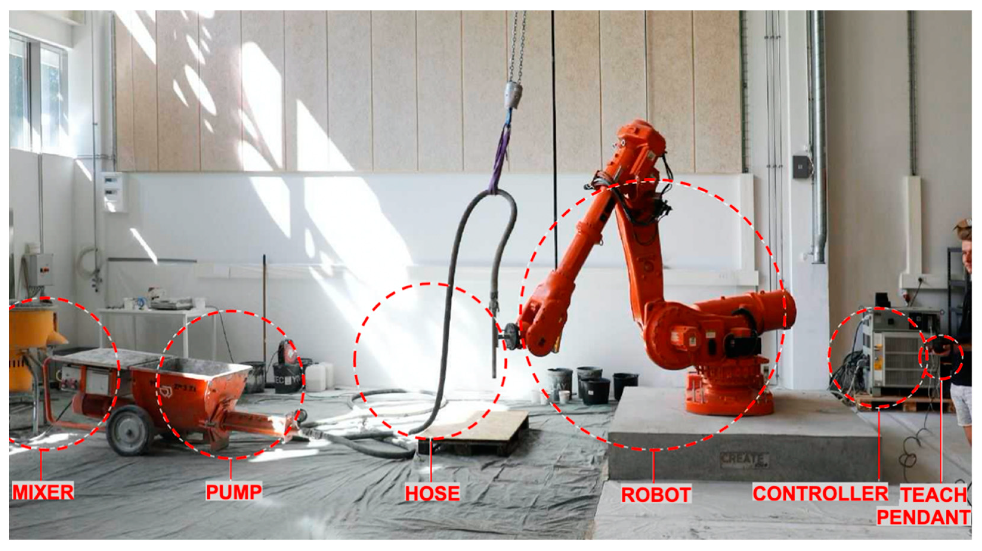
Figure 1. Components of an AM robotic arm for concrete printing.
Applsci 11 03865 g001
Figure 2. Transportation simulation for the house models (dimensions are in millimeters).
Applsci 11 03865 g002
Figure 3. The process map for Scenario 1.
Applsci 11 03865 g003
Figure 4. The process map for Scenario 2.
Applsci 11 03865 g004
Figure 5. The process map for Scenario 3.
Applsci 11 03865 g005
Figure 6. The process map for Scenario 4.
Applsci 11 03865 g006
Figure 7. The process map for Scenario 5.
Applsci 11 03865 g007
Figure 8. The process map of Scenario 6.
Applsci 11 03865 g008
Figure 9. The process map for Scenario 7.
Applsci 11 03865 g009
Figure 10. Cost components for the scenarios.
Applsci 11 03865 g010
Table 1. Seven distinct scenarios for the research analysis and their designated names.
Technologies
Round house Applsci 11 03865 i005Supply chain configuration3DCPConventional construction
On-siteScenario 1
(On-site printing of round house: ONP-RND)
Scenario 3
(On-site conventional construction of round house: ONC-RND)
Off-siteScenario 2
(Off-site printing of round house: OFP-RND)
-
Rectangular house Applsci 11 03865 i006On-siteScenario 4
(On-site printing of rectangular house: ONP-RECT)
Scenario 6
(On-site conventional construction of rectangular house: ONC-RECT)
Off-siteScenario 5
(Off-site printing of rectangular house: OFP-RECT)
Scenario 71
(Off-site conventional construction of rectangular house: OFC-RECT)
1 Scenario is not fully comparable to others, since the numbers include the profit margin of the prefabrication company.
Table 2. Project component specifications.
ItemEquipment or Raw Material SpecificationsPricing (EUR)
Printing machineryKuka robotic arm KR120 R3900 + concrete pump [51]135,000
Concrete mixerM-tec duo connect [52]15,000
Forklift3 tons lifting capacity35,000
Raw materials for conventional methodsGeneric concrete and formwork materials110 per m3
Raw material for 3D printingPremixed dry material in 1-ton bags150 per m3
Table 3. Schedule comparison of all scenarios.
ScenarioPre-ConstructionConstructionPost-ConstructionTotal (h)
S1 (ONP-RND)11 h21.5 h3 d4 days 8.5 h
S2 (OFP-RND)8.16 h21.5 h14 d 7.5 h15 days 13.16 h
S3 (ONC-RND)2 h34.4 h28 days29 days 12.4 h
S4 (ONP-RECT)11 h27.3 h3 days4 days 14.3 h
S5 (OFP-RECT)8.16 h25.3 h14 d 7.5 h15 days 16.96 h
S6 (ONC-RECT)2 h35.8 h28 days29 days 13.8 h
S7 1 (OFC-RECT)6 months 1 h30 h1 days6 months 2 days 7 h
1 Not fully comparable with other scenarios since the data take the subcontractor’s perspective of buying the modules from a prefabricated module supplier rather than the prefabricated module manufacturer itself.
Table 4. Required equipment for transportation.
ItemSpecificationCost of Rental Per Day (EUR/day)Application
Truck, 2-axle (including the driver)16.2-ton capacity [54]1000Transportation of robot
Crane truck (including the operator)50-ton capacity1139Movement of walls on the site
Forklift3-ton capacity9.33Movement of robot on-site
Concrete mixer truck6.1 m3 capacityEUR 164 + EUR 200/h (operator + truck)Mixing concrete
Table 5. Cost comparison of the scenarios per house.
ScenarioMachinery and Production Equipment (EUR)Material (EUR)Labor (EUR)Transportation (EUR)Total (EUR)
S1 (ONP-RND)100.27
(2.9%)
1056.61
(30.4%)
1934.45
(55.6%)
386.17
(11.1%)
3477.5
S2 (OFP-RND)1025.71
(20.1%)
1056.61
(20.7%)
2165.45
(42.4%)
865
(16.9%)
5112.77
S3 (ONC-RND)-3556.89
(43.4%)
4000.75
(48.8%)
639.52
(7.8%)
8197.16
S4 (ONP-RECT)117.83
(2.7%)
1505.6
(34.1%)
2335.13
(52.9%)
451.75
(10.2%)
4410.31
S5 (OFP-RECT)1043.27
(17.5%)
1505.60
(25.3%)
2482.13
(41.6%)
930
(15.6%)
5960.99
S6 (ONC-RECT)-4295.65
(54.1%)
2925.99
(36.8%)
721.61
(9.1%)
7943.25
S7 (OFC-RECT) 1813.6
(6.3%)
10,296.75
(80%)
1255.16
(9.75%)
500
(3.9%)
12,865.51
1 Scenario is not fully comparable with others, since the numbers include the profit margin of the prefabricated module manufacturer.
Publisher’s Note: MDPI stays neutral with regard to jurisdictional claims in published maps and institutional affiliations.