Article

Seismic Evaluation and Methods of Rehabilitation of Old Masonry Buildings in the Bay of Kotor (Montenegro)

1
Faculty of Technical Sciences, Department of Architecture, University of Priština in Kosovska Mitrovica, ul. Knjaza Miloša 7, 38220 Kosovska Mitrovica, Serbia
2
Faculty of Technical Sciences, Management in Construction, University of Priština in Kosovska Mitrovica, ul. Knjaza Miloša 7, 38220 Kosovska Mitrovica, Serbia
3
Faculty of Architecture, University of Montenegro, Bulevar Džordža Vašingtona b.b., 81000 Podgorica, Montenegro
4
Primary School, Prizrenska 37, 11080 Belgrade, Serbia
*
Author to whom correspondence should be addressed.
Appl. Sci. 2021, 11(8), 3544; https://doi.org/10.3390/app11083544
Submission received: 20 March 2021 / Revised: 11 April 2021 / Accepted: 12 April 2021 / Published: 15 April 2021
(This article belongs to the Special Issue Theory and Modelling of Historic Masonry Architecture)

Abstract

:
Old load-bearing masonry buildings exist all around the world. The cultural and architectural heritage value of these buildings and the consciousness of public opinion have led to a need for safeguarding and preservation policies for these architecturally valued buildings and urban aggregates. This paper provides the information on the constructive and structural details of the old buildings dating from the 12th to 19th century in the Bay of Kotor and discusses their seismic and dynamic behaviour, identifying structural fragilities and consequently their vulnerability. One factor that significantly influences the seismic vulnerability is the quality of workmanship, which has, in conjunction with the lack of maintenance of the buildings, increased the seismic vulnerability of heritage masonry buildings in general. Masonry constructions represent an important part of Montenegrin Architectural Heritage. The existing heritage masonry buildings in the Bay of Kotor suffered major earthquakes with repairs ranging from minor repairs to partial rebuilding. No degree of seismic resistance to any potentially severe shaking levels has been determined for the surviving buildings. The lack of strategies, policies and actions by the institutions responsible for this domain in the course of the second half of the 20th century drove these buildings to the state of serious degradation. The adoption of intrusive and inadequate rehabilitation and conservation practices, using new materials and construction techniques on structural and nonstructural elements, has strayed away from traditional knowledge and practices. The main objective of this research is understanding the whole building process that underpins a historical construction, and building techniques and other methods applied in building the architectural and engineering structures constituting the present Historical Heritage in Montenegro.

1. Introduction

Unreinforced masonry (URM) buildings are among the most common types of buildings in the seismically active zones of Southern and Central Europe. Some of them possess a high historical value and could therefore be classified as part of the architectural heritage, requiring special attention with regard to their preservation and retrofitting measures [1].
Organizations such as The Masonry Society and the Federal Emergency Management Agency have found, after numerous earthquakes, that the damage to the unreinforced walls causes greater material damage and a higher rate of fatalities than any other structural element [2,3].
In the case of historical buildings in general, large differences are evident in terms of structural assembly, construction techniques and properties of the applied construction material.
The study of old construction techniques is important not only from the perspective of the history of architecture and construction, but also from the aspect of application of traditional or compatible modern construction procedures in the process of rehabilitation, reconstruction and adaptation of historic buildings.
Awareness of the need for seismic strengthening of buildings is of crucial importance, the so-called local seismic culture, which is conditioned by the frequency of earthquakes in a given period. The continuity and interruptions of seismic culture in traditional construction can be understood and followed by earthquake research throughout history, where the dates of seismic shocks, their intensities, and magnitudes are analysed. The more frequent and stronger an earthquake is, the more pronounced is the local seismic culture. This, among other things, explains the presence of appropriate seismic constructive solutions on masonry structures in the area of the Bay of Kotor dating from the 16th to 18th century (major earthquakes occurred in the years 1559, 1563, 1608, 1632, 1639, 1667, 1750 and 1780).
The most recent earthquake in the Bay of Kotor area and the entire Montenegrin coast that occurred in 1979, as well as the previous major earthquakes, showed, to the extent traceable on the buildings and through historical sources, aside from shortcomings, many qualities of traditional construction. Certainly, such quality was, among others, conditioned by the financial standing of the client, either an individual or a community, as well as by the knowledge of construction systems and techniques, economic and cultural ties with developed regions. Effects of earthquakes on ancient masonry buildings, as well as the ones that cover cultural and social importance regarding effects on earthquakes and repair techniques, are presented in the papers of the following authors [4,5,6,7].

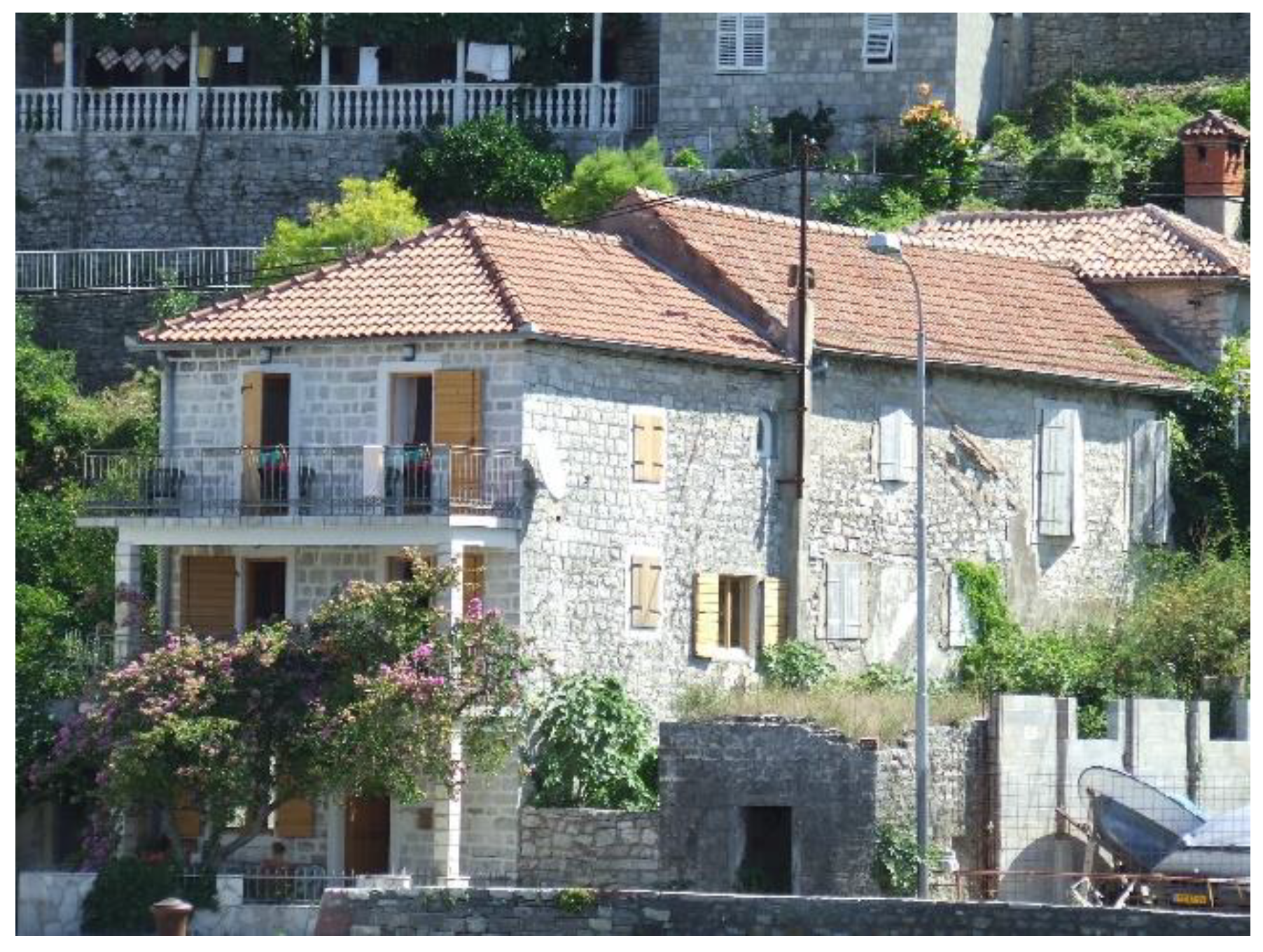
2. Building Characteristics

The historic buildings of the Bay of Kotor, as well as the wider surrounding area, are usually masonry, massive, nonframe, made of stone as the basic building material and lime mortar as a binder.
Masonry structures are affected by significant seismic forces in proportion to their mass. They are insufficiently resilient to tensional and shear stress; they have low ductility (plasticity) and relatively small capacity for stress redistribution. However, the seismic resistance of these buildings may vary to a large extent, depending on the soil and the method of foundation, architectural form, the original quality of their structural elements and construction techniques, maintenance methods and so on.
It is difficult to determine to what extent the old builders intentionally designed the structures to be aseismic both regarding the entire structure and its elements. Nevertheless, it is evident that, in the overall construction process, they primarily took into account the structural load and general safety of the building and often achieved extraordinary results from the aspect of their earthquake resistance.
Regardless of whether the entire structures or their individual elements had originally been intentionally designed as earthquake resistant, it is important to understand their role and contribution to the favourable behaviour of the building during an earthquake. Gaining an insight into the original seismic properties of architectural heritage would contribute to having minor interventions and more rational solutions for their structural rehabilitation, that would, among others, be beneficial from the aspect of preserving the original structural assembly as the essential feature of historical buildings whose authenticity is particularly valued.
The continuous uniform distribution of stress is closely related to the stated properties of architectural form: symmetry, simplicity and regularity. It has been proved that buildings, having their load-bearing structural elements evenly distributed, with continuous walls without abrupt changes in thickness, have the maximum chance of surviving an earthquake. The axial arrangement of the openings and vertical strips of walls between openings along the entire height of the building are also essential. Any disturbance of the full—empty relationship on the floors would lead to unwanted damage. Such examples are far more uncommon in traditional buildings than in modern ones.
It is particularly interesting that with regard to the earthquake-resistant properties, the openings in the walls (doors, windows) were the subject of special attention of the old builders. Segmental or flat relieving arches or somewhat simpler arches on three joints were usually placed above the window sills and lintels.
Vaults and arches were among the frequently used constructive elements. Some of them, especially those precisely carved of stone from the Đurići quarry, with narrow joints and raised lanced arches, are extremely good aseismic structures, which was proved by their stability in earthquakes, including the latest one in 1979 (Figure 1 and Figure 2) [8].
These masonry buildings represent a box-type structural system composed of vertical structural elements—walls—and horizontal structural elements—floors and roofs. Vertical loads are transferred from the floors, acting as horizontal flexural members, to the bearing walls, and from the bearing walls, acting as vertical compression members, to the foundation system.
The most common technique uses “cornerstones”, stones of a larger size than those used in the walls and typically of regular shape. Effective coupling of orthogonal directions through the thickness of the walls is possible. Also, the efficient system of restraining building walls to maintain the box was made with wooden or iron chaining.
Accurate prediction of the seismic response of such structures has often proved to be difficult, not only due to the complex geometrical features of their individual architectural parts, but also due to the composite and nonhomogeneous nature of URM [1].

3. Aseismic Properties
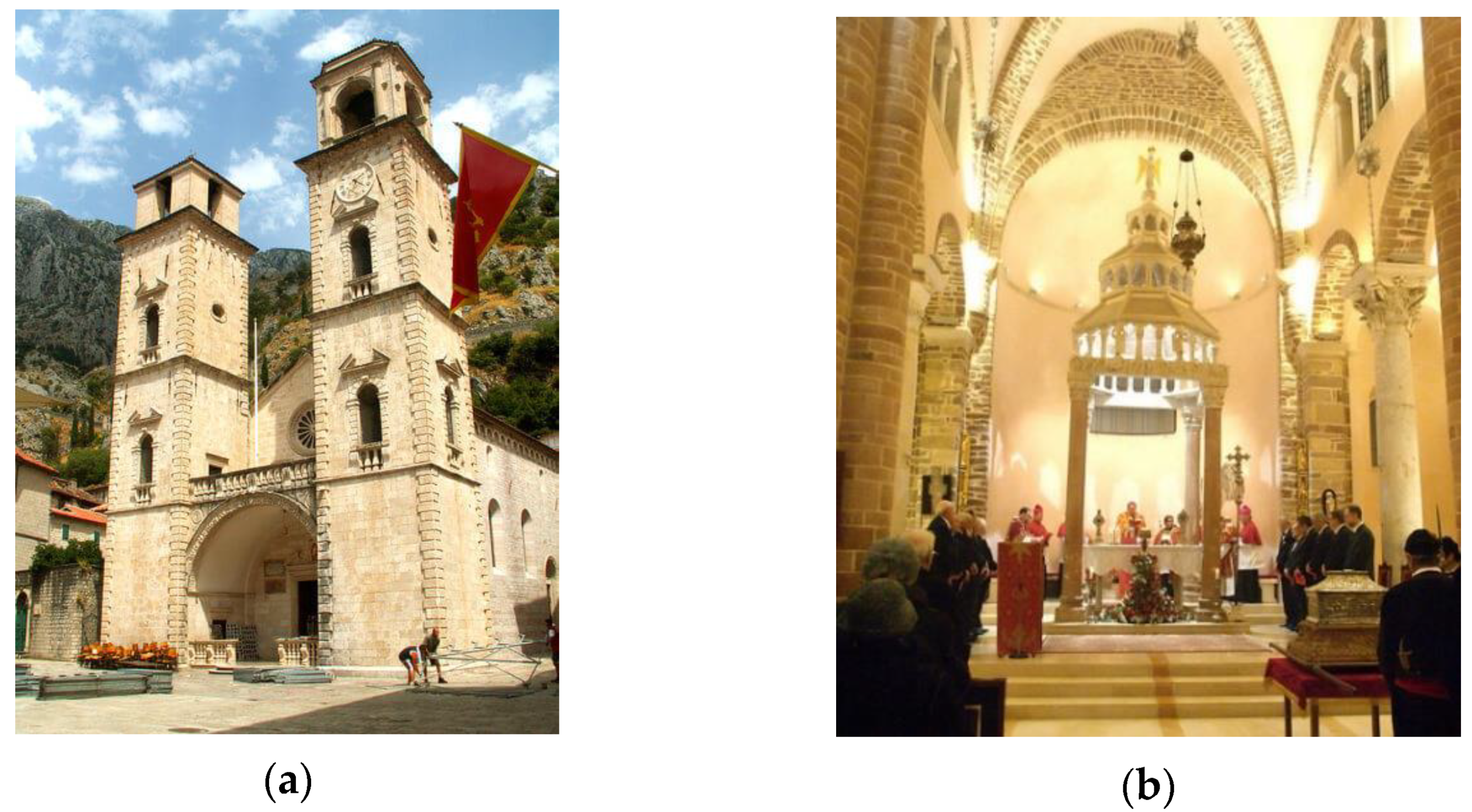
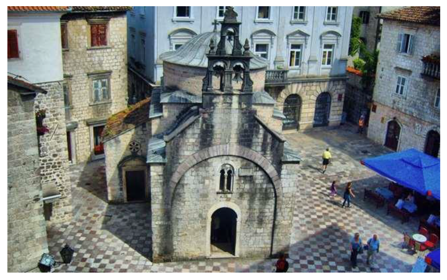
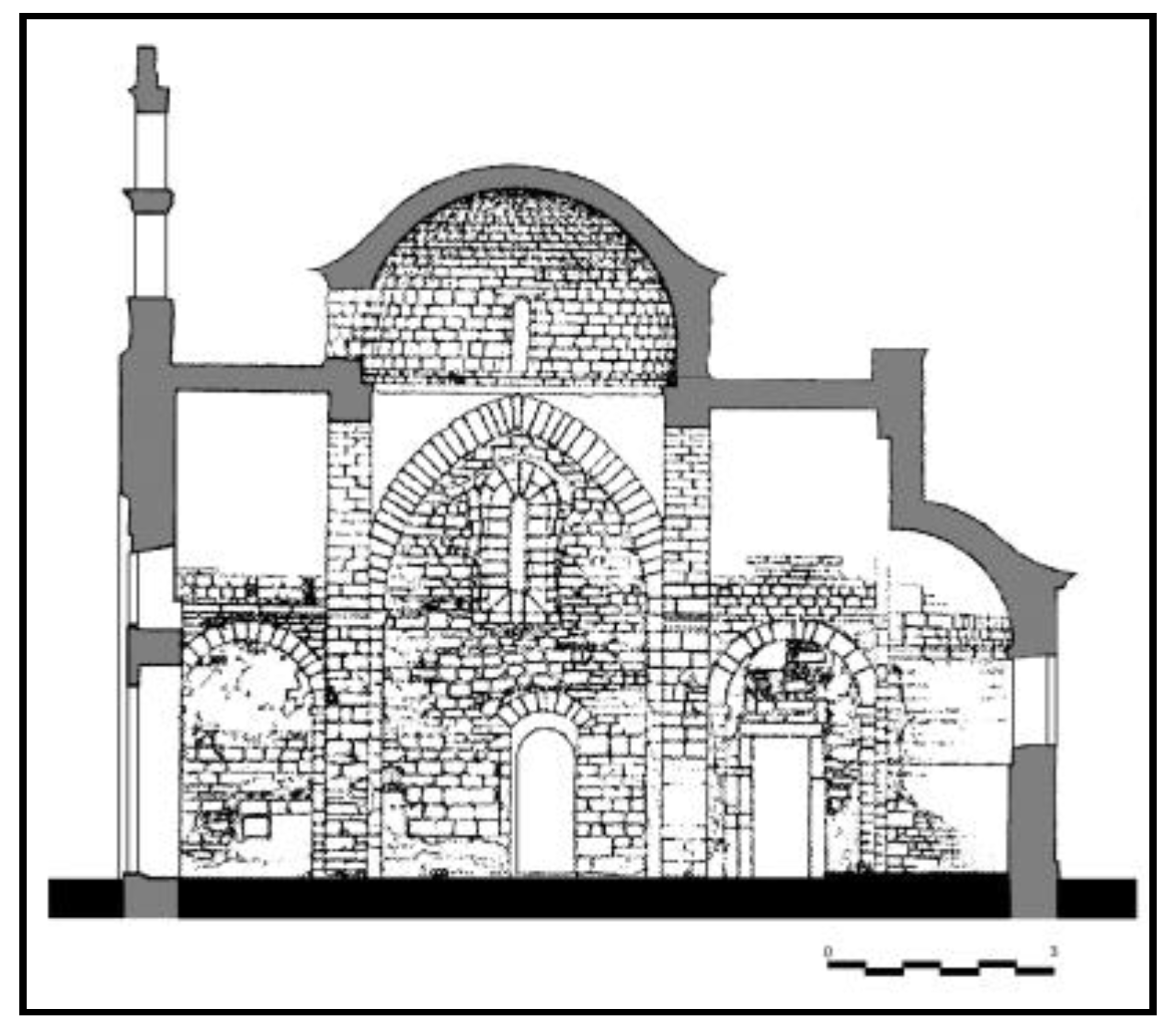
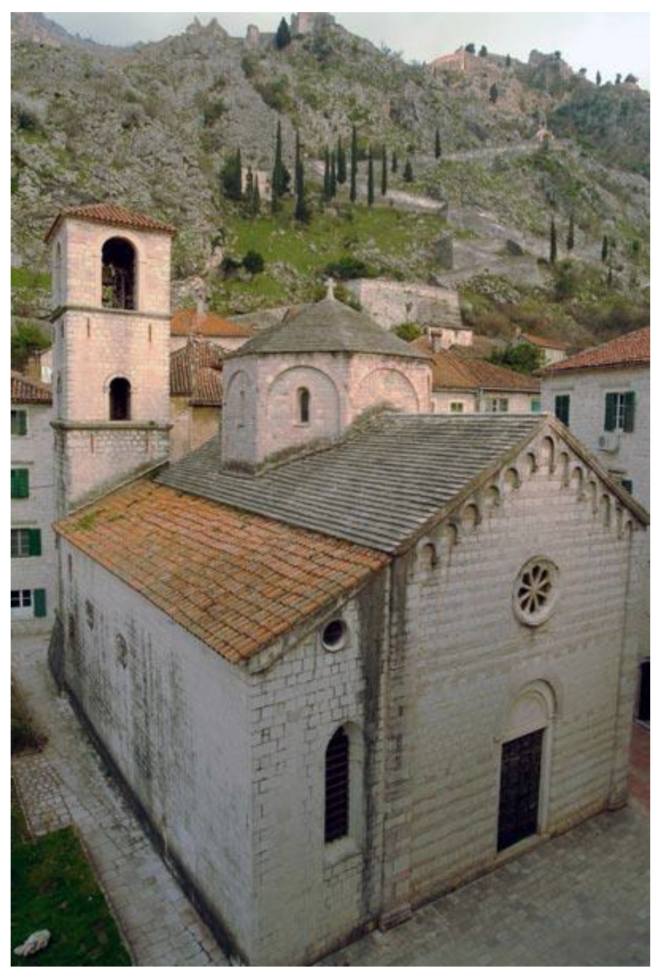
3.1. Monuments

The earthquake-resistant (aseismic) properties of traditional architecture in general have been ultimately confirmed by the very existence of very old authentic buildings, even in the most distinct seismic zones. In the area of the Bay of Kotor, the example of Kotor is particularly characteristic, with a number of Romanesque, primarily sacral buildings located there (from the 12th–14th century). The churches of St. Luke and St. Mary of Rijeka have preserved their original architectural structure during their eight-century history, surviving, among others, numerous turbulent seismic events.
However, considering that according to the sources, there were no major earthquakes at the time of the construction of these churches, nor much earlier, it can be concluded that the aseismic component had been brought from outside, together with other elements of the applied construction. This assumption would be completely in line with the repeatedly emphasized similarity of the churches of St. Luke and St. Mary with the construction properties of Attica and Apulia, the two most seismically distinct neighbouring areas.
As tall buildings are very rare in traditional construction (towers, bell towers), cases of overturning are also exceptional. Such a catastrophic case happened in 1667 with the Romanesque bell towers of the Cathedral of St. Tryphon (Figure 3a,b), which collapsed and damaged nearby buildings on the square. The extent to which this earthquake influenced the strengthening of the local aseismic culture has been demonstrated by the fact that the present bell towers, built at that time, did not show the slightest constructive damage in the 1979 earthquake.
It is known that the bell tower of the church of St. Luke was destroyed and renovated several times, and this was the case with other sacral buildings as well (Figure 4 and Figure 5).
Similar to the belvedere structures in the historical buildings, there are domes in the central part at the roof level of sacral buildings. Depending on the size, shape and the design solution of the dome and other upper parts of the building, these elements radically differ from each other regarding their seismic response.
The much larger dome of the Cathedral of St. Tryphon in Kotor had a similar fate. In addition to the fact that the foundation of the eastern part of the Cathedral of St. Tryphon was constructed in the rock and the western on the embankment, the original dome was exposed to the most unfavourable influences due to the different seismic behaviour of the structure at its ends. The sudden discontinuity and the effect of the so-called “soft story at the ground floor” contributed to the damage of the dome. Namely, the dome was supported by free-standing elements (columns and pillars) that were exposed to strong seismic vibrations during the earthquake, eventually causing its fall.
The domes of the churches of St. Luke and St. Mary are much better connected with the lower structures, walls and leaning and transverse arches (Figure 6 and Figure 7). In the case of the church of St. Luke, above the usual profiled wreath, there are two more rows of very long (45–55 cm) and low (13,10 cm), meticulously processed square stones. This particular ring beam was made in accordance with modern theoretical standards and played a crucial role in managing tension forces at the bottom of the dome, and significantly contributed to the stability of the entire building, successfully applying tension forces and combining the lateral and transverse arches. These elements are also known in Byzantine construction, also with occasional blocks being interconnected by metal anchors, in order to act on the principle of a chain.
A similar construction concept was applied to the Church of St. Mary of Rijeka, dating from the beginning of the 13th century. It is important to note that on the example of these churches, during the rehabilitation after the earthquake in 1979, a method of reinforcement compatible with the original construction was applied. These are the ring beams and tie-rods in the upper zone (under the roof, at the top and at the bottom of the dome) with minimal interventions or recess cutting [8]. Poor quality of the constitutive masonry material and the insufficient rigidity of floors and roofing systems are the main causes of seismic vulnerability and, consequently, of collapse mechanisms. High-quality masonry and well-connected walls play a crucial role in limiting damage formation and reducing global seismic vulnerability.

3.2. Aseismic Characteristics of Historical Buildings

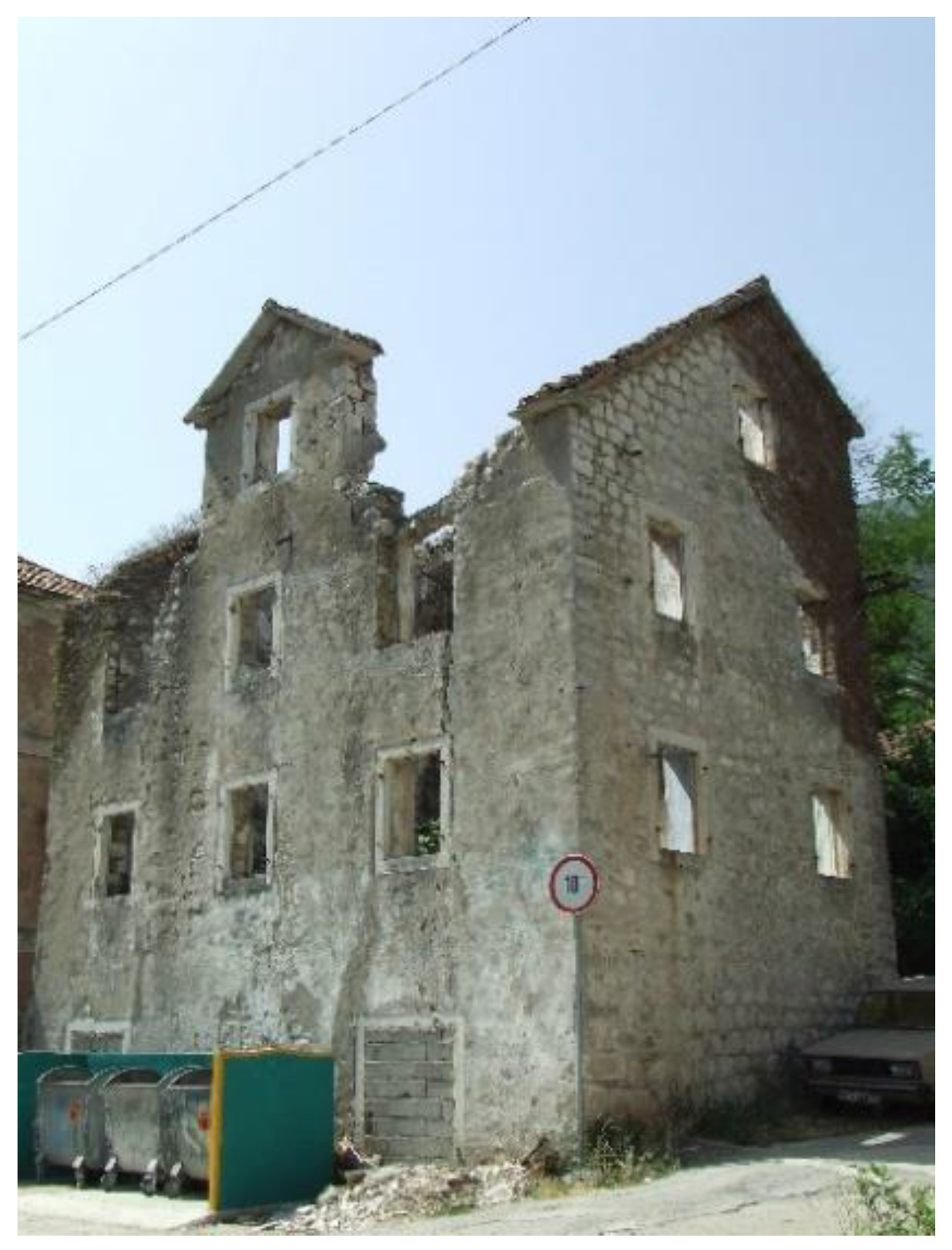
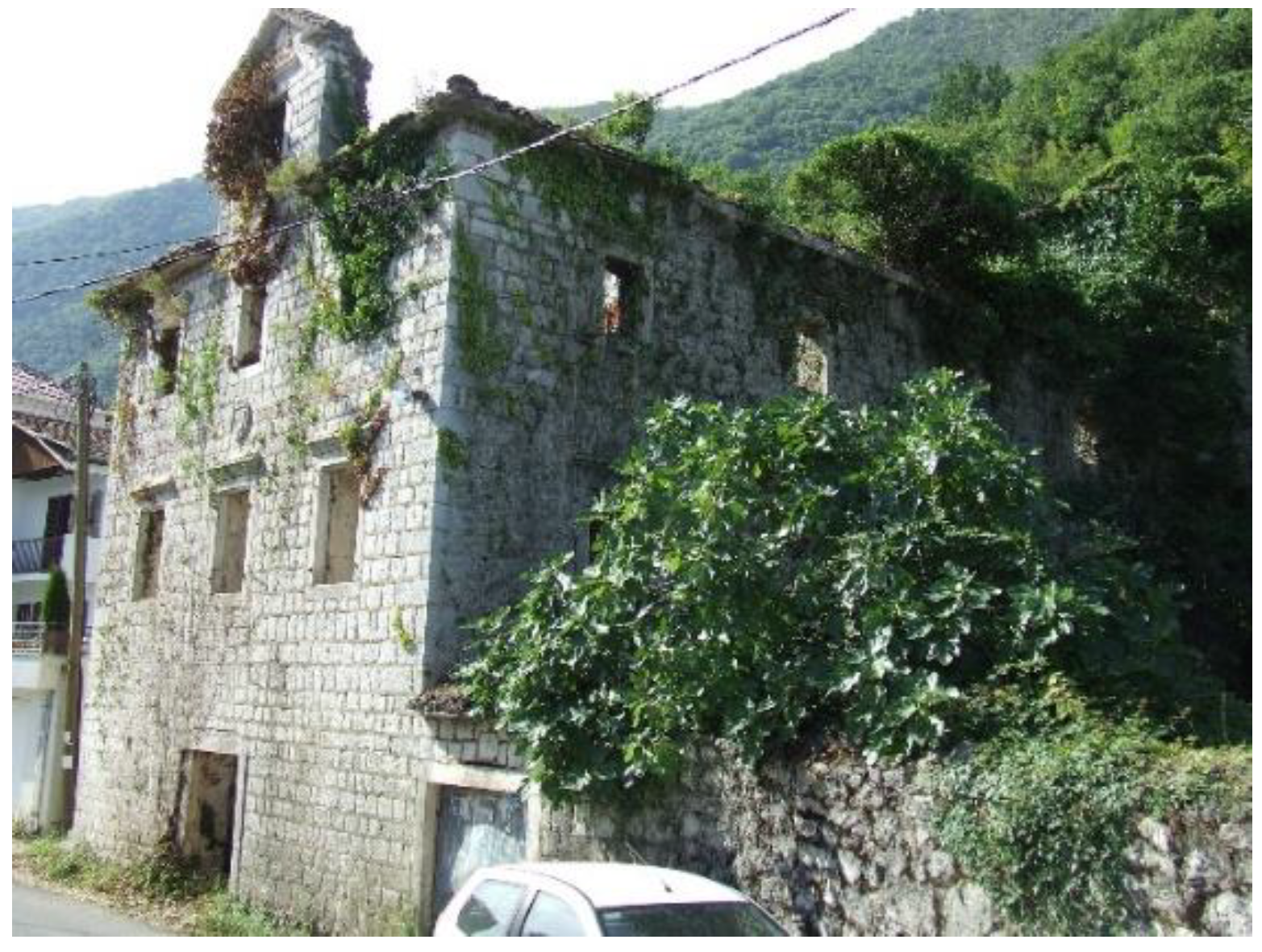
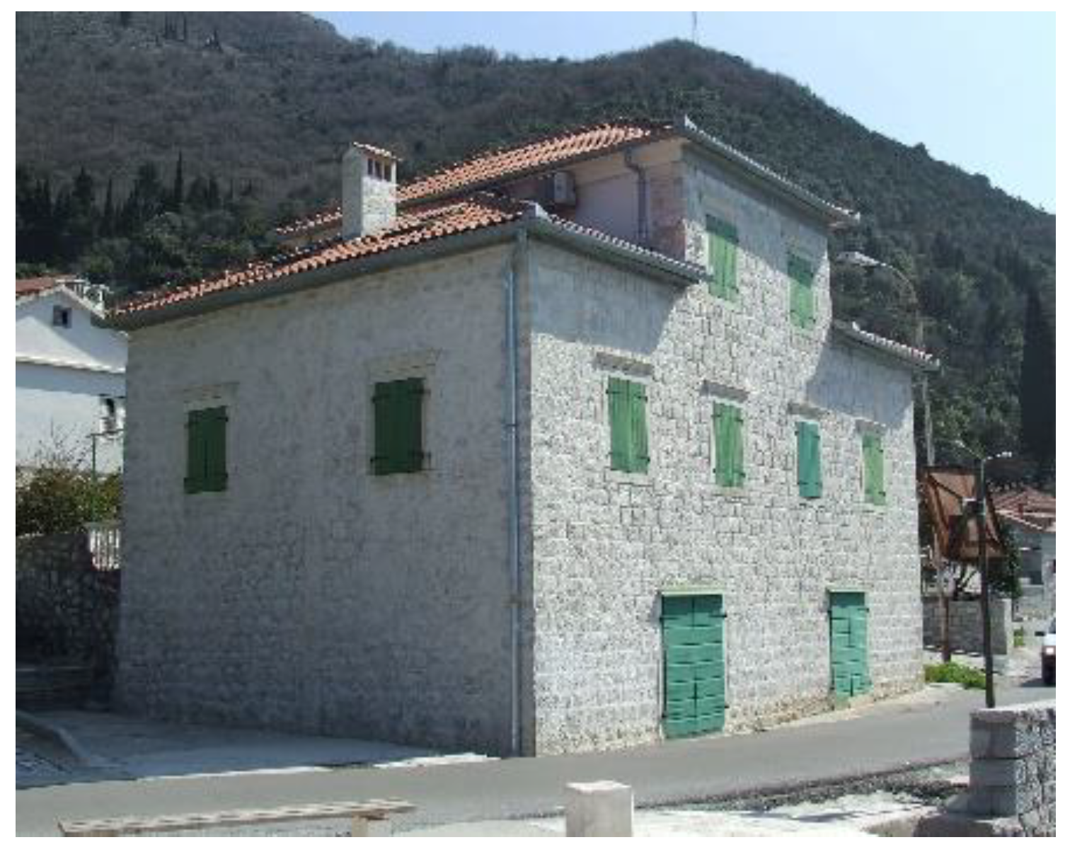
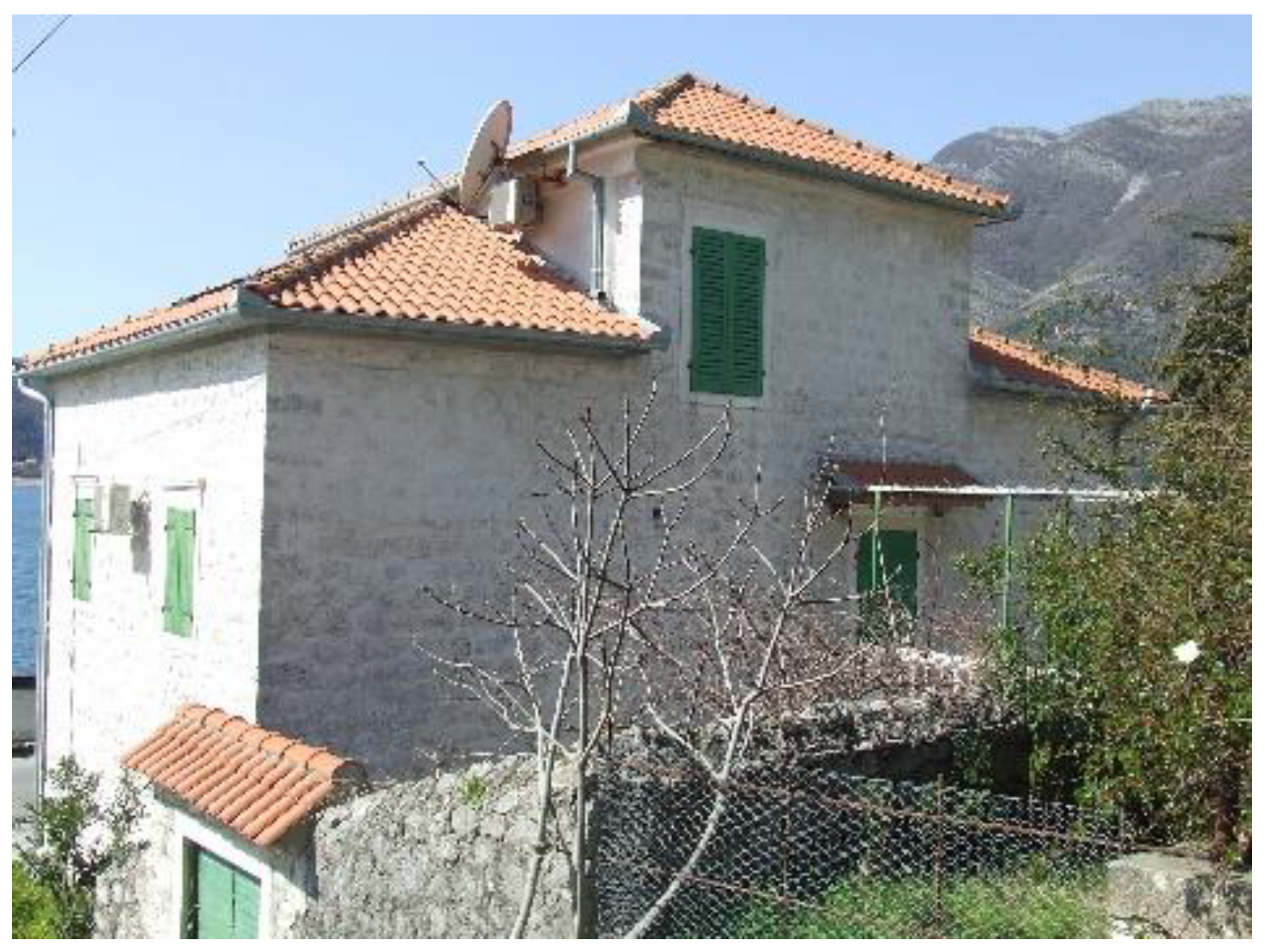
3.2.1. Single Houses
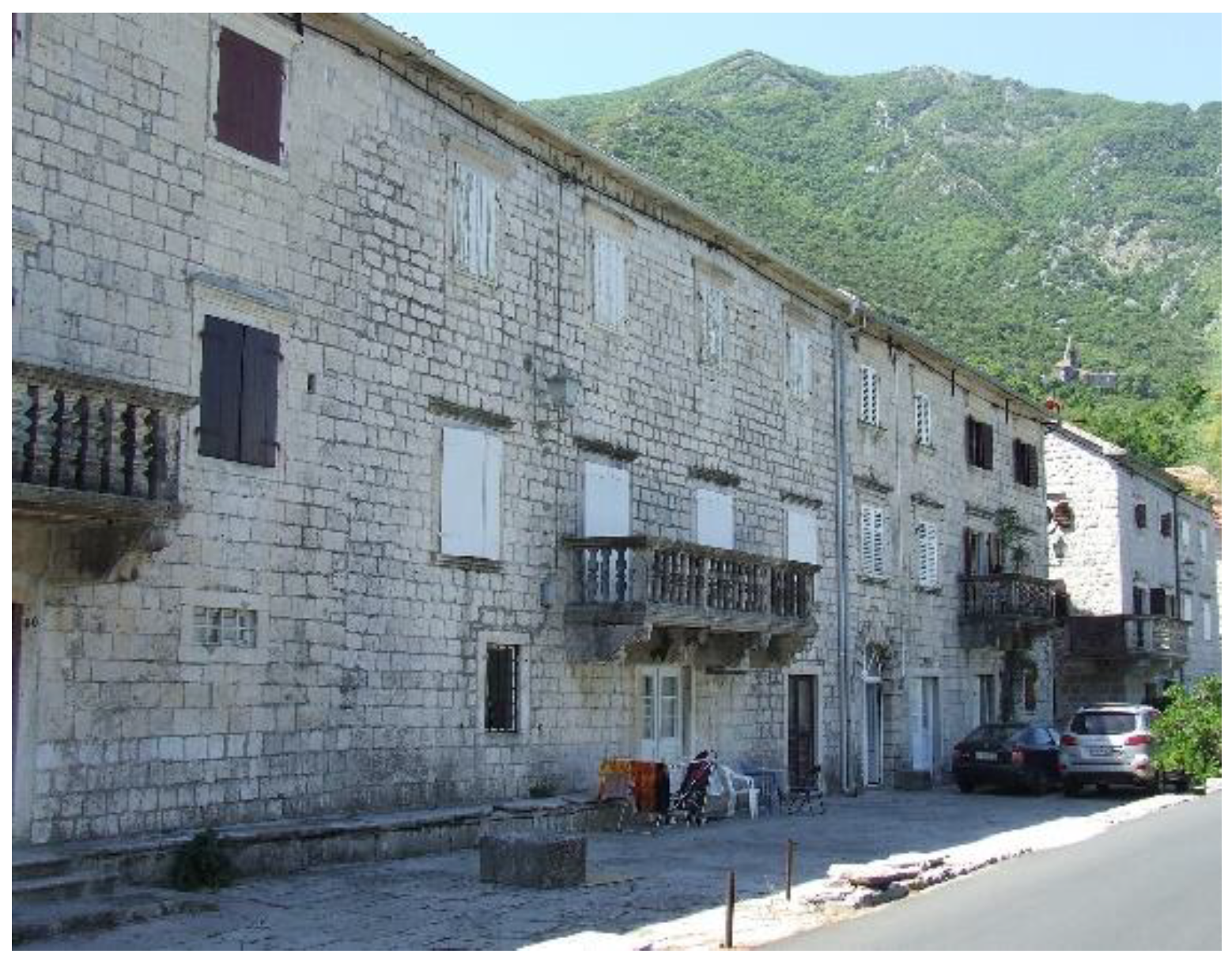
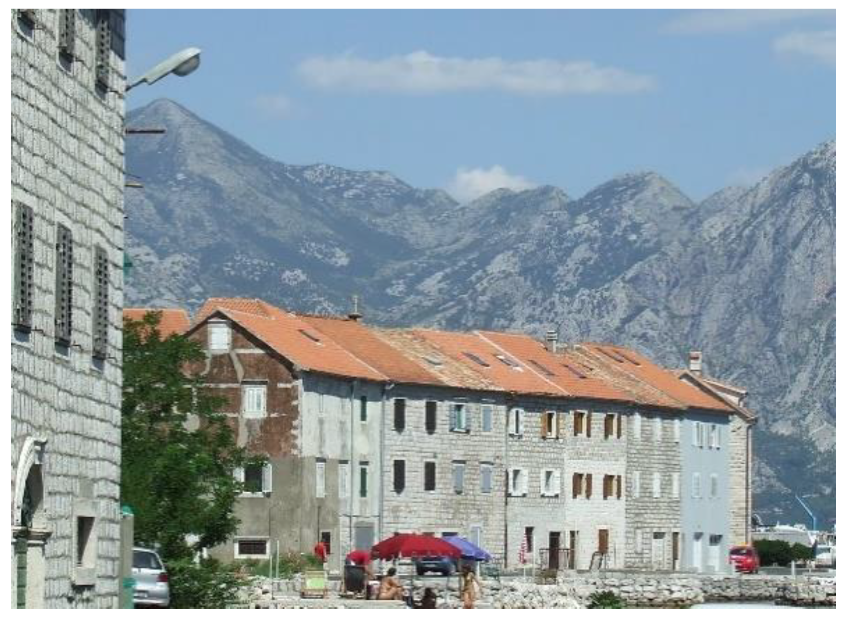
The configuration of the building, the construction design and the architectural form have a significant influence on its behaviour in an earthquake. Experience has shown that simple structures have the greatest chance of surviving. This type of building is easy to build, maintain and repair. Its response to an earthquake can be relatively easily determined and analysed. If the building is symmetrical, compact and not too elongated, it will behave much better in an earthquake. On the other hand, if a building does not possess such properties, it may be exposed to torsion and various influences at its ends. Corner damage often occurs at the corners of buildings due to the stress concentrations that occur at the intersection of perpendicular walls. Instability of corner sections often occurs because two sides of the corner are unrestrained. Therefore, the corner section is free to collapse outward from the building.
In the Bay of Kotor, the buildings are, as a rule, simple, mostly rectangular, symmetrical, compact and with relatively uniform dimensions of the base and other proportions.
The most representative single houses of the bay have the so-called belvedere room in the attic, which is the prominent central part of the facade with a pair of window shafts. Despite the original trend that was later chiefly abandoned, to connect this part of the façade with the rest of the structure using wood beams—tie rods and iron anchors (ital. capochiave), during the earthquakes, a concentration of stress would occur, causing cracks along the horizontal joint with even the case of the whole belvedere structure collapsing at the point of discontinuity, that is, the place where the wall façade canvas narrows (Figure 8 and Figure 9). Cracking and collapse of the front and back façades during earthquakes is the most frequent failure of the system caused by this fragility [9].
Out-of-plane bending of walls is a very frequent mechanism. Horizontal inertia actions are transferred from the floor structures, which should act as rigid horizontal diaphragms, into the bearing walls, causing shearing and bending effects, and from the bearing walls into the foundation system. Additionally, due to the distributed mass of wall elements, distributed inertia forces are induced, resulting in out-of-plane bending of walls.
The possibility of overturning of large parts of walls, facades and bell towers is certainly the most critical hazard in this kind of structure. Small tensile strength of masonry favors separation of external walls from the main body of the building, progressively turning them into freestanding walls.

3.2.2. Row Houses

Row houses, which are most common in urban environments of the bay such as Kotor, Perast, Risan, Muo and Stoliv, do not have independent structural behaviour (Figure 10 and Figure 11). They share midwalls with adjacent buildings, interacting among themselves. The evolution of the urban layout is an important issue because of the chronological construction process in which adjacent buildings share load-bearing masonry walls and others use existing masonry and partition walls for floor and roof support.
This aspect is important not only for vertical load-bearing capacity, but also for seismic actions, and hence seismic vulnerability. Most of the row buildings have a low-quality connection between walls, particularly at wall corner angles.
The analysis of buildings belonging to an aggregation is different than the case of an isolated building [10], because of the several interactions that the adjacent volumes could act on the structural unit which is analysed. The main structural interaction may be classified into two categories [11], vertical loads or horizontal actions (especially under the seismic action) from adjacent buildings; buttressing or constraining effects offered by the adjacent buildings. These interactions modify the collapse mechanism of the aggregation and of its structural unit introducing new different actions and changing the constraint configuration. Lack of alignment between façades causes the lack of contrast from adjacent buildings, as in the case of head buildings in rows. Another vulnerability source could be the different height of the buildings, with stiff changes that might lead to possible collapse of the higher one. Floors at different levels in adjacent buildings could act against the common wall.

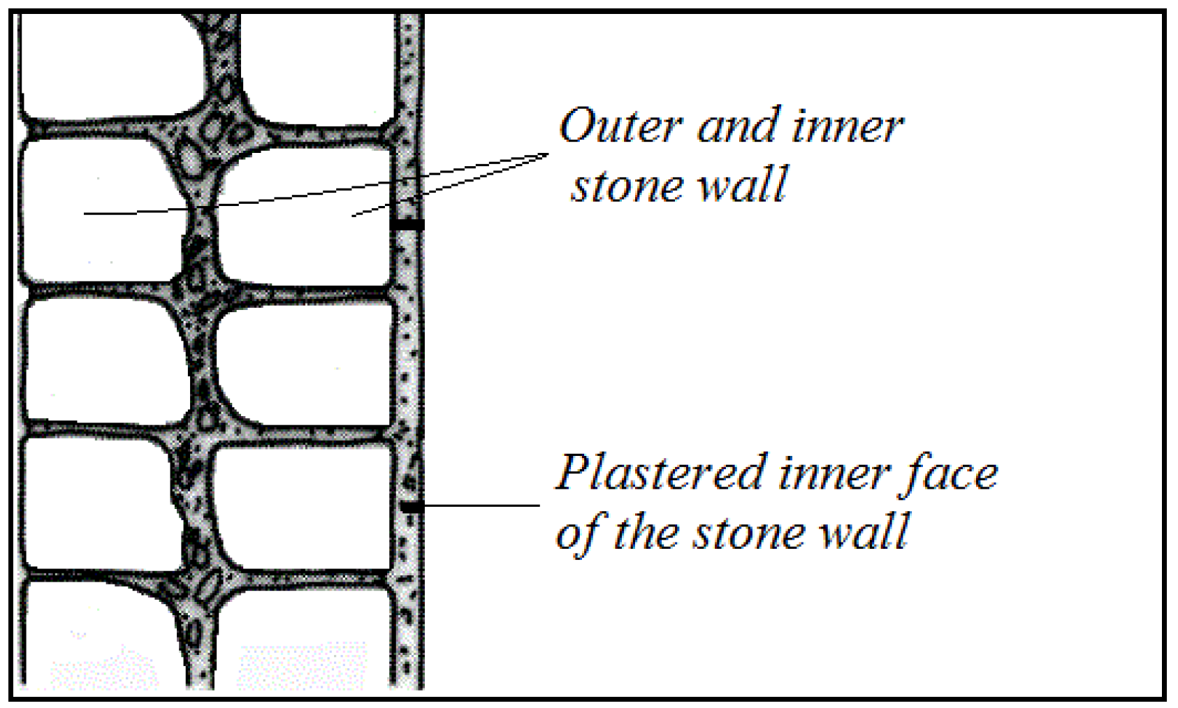
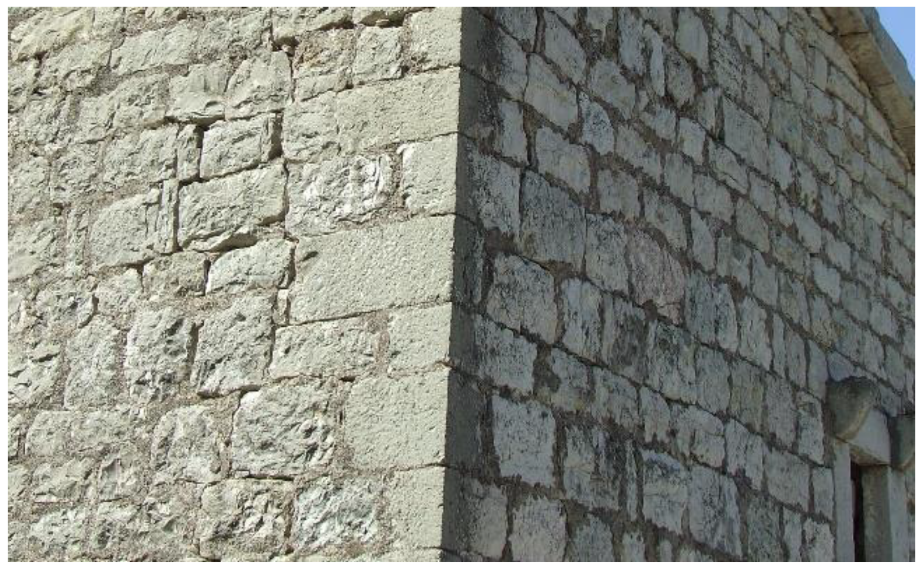
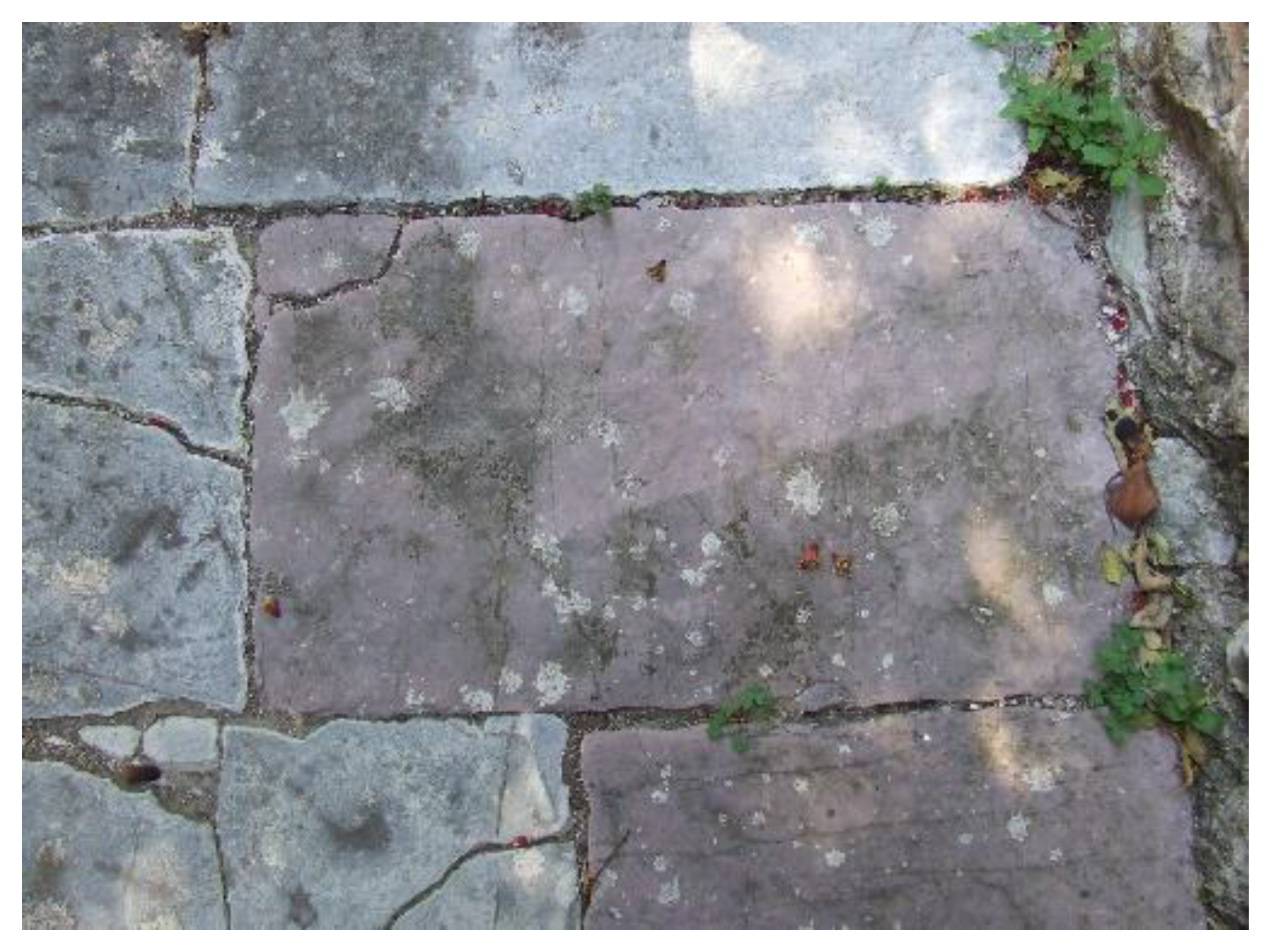
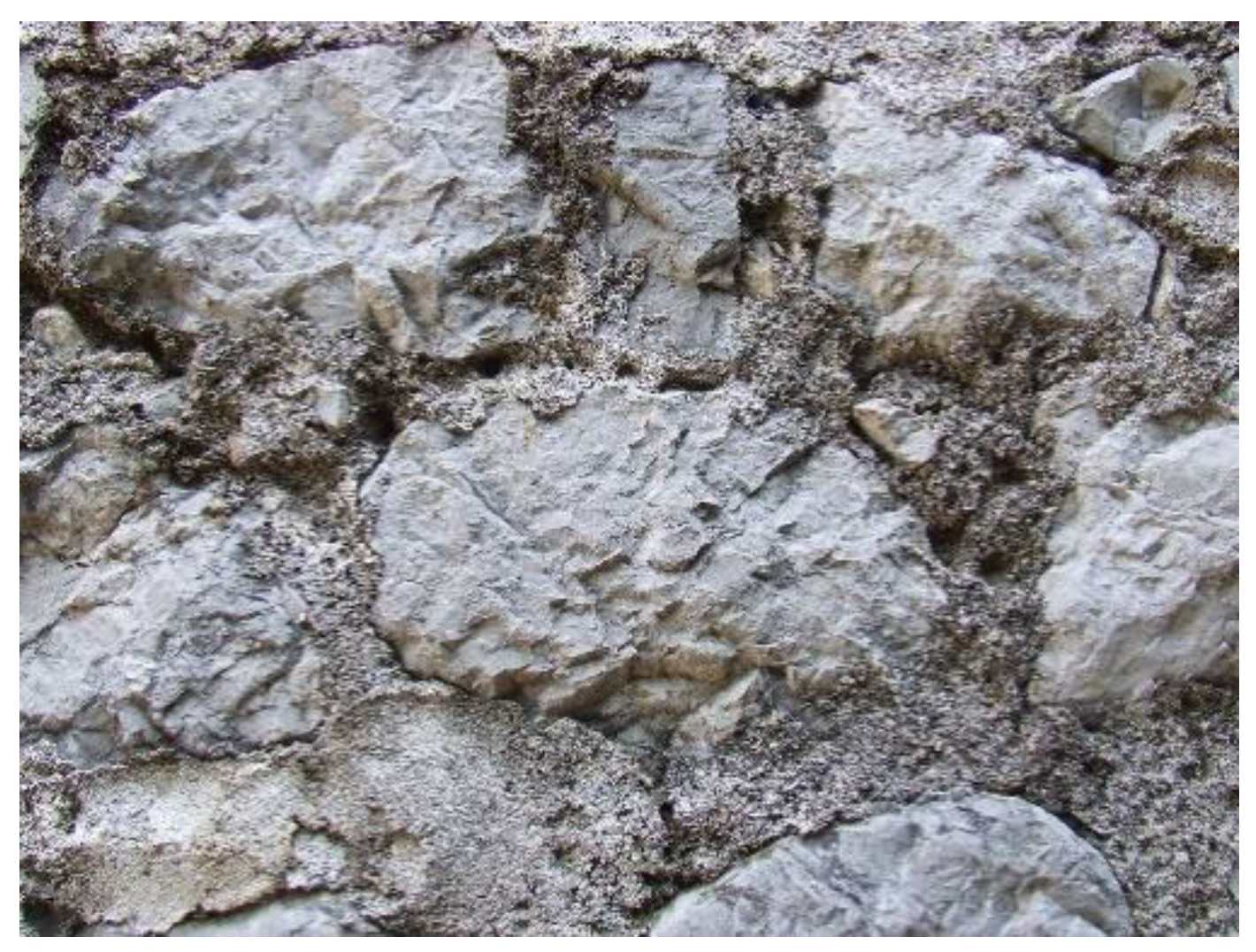
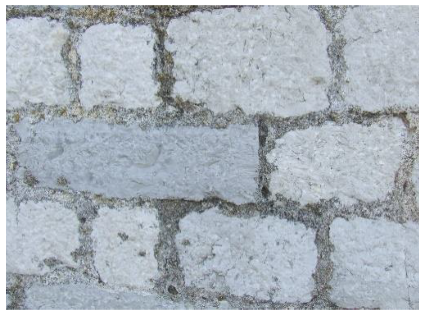
4. Construction Elements and Techniques

The dimensions and nobility of buildings are ruled by the architectural typology and traditional construction techniques. In the majority of buildings that were analysed, the systematic use of wood was observed in structural elements of floors, roofing structures, floor coverings, and interior partition walls.
As a rule, multiple-story houses were built on solid ground. House foundations at the seaside were immersed in underground waters, if not in the sea itself. Nevertheless, the walls of these houses have not yet shown signs of cracking or any kind of subsidence.
The foundations were made of flagstone or larger blocks of different sizes, and their depth did not exceed 50–60 cm. In the case of loose soil, excavations would be more than one meter deep, while no foundation was required for the buildings constructed the rock. The width of the stone wall varied from 70 to 80 cm, while the binding agent used was lime mortar, or sometimes also the terra rossa (the red soil), known to be a good binding agent.
Walls were built using local stone immersed in hot lime mortar or sand, clay, or even in eggs, which were occasionally used as a binding agent. These walls are formed of an outer and an inner wall. The space between the two is filled with small pebbles (“sovrnja”, Lat. sauornam) and in most cases lime mortar (Figure 12).
One large stone was used to connect both sides of the walls at every 2–3 m interchangeably in each row, thus fitting the two walls together (Figure 13). This stone and procedure are called “wall binding” by stonemasons. Corner blocks can be seen at the corners of the houses. They are slightly larger in size, more evenly processed, their colour being a darker grey, and they partially have the bearing function in the stone houses.
Venetian feet (34.77 cm) were used to measure the wall thickness. This was the measurement unit in civil engineering until the end of the 19th century in the whole Bay of Kotor area.
The thickness of walls of some houses is 72 cm (two feet), while upper floors are thinner, being up to 66 or 60 cm.
Outer walls were built using the thoroughly treated fine stone (made from carved stone blocks) 17–25 cm in height. Side walls were built using less regularly shaped blocks than those on the front facade of the house. Thick stone walls ensured lower interior temperatures during the summer months, and retained heat for a longer time in winter. During construction works the local stone on the main facade (in more wealthy owners), was substituted with the Korčula stone. They would contribute to the beauty of the building, and at the same time reflect its owner’s wealth.
Stone was not particularly processed for interior walls, except for several flagstones above the window, where they formed a discrete arch. Vaults were built using 5–6 cm thick flagstone taken from local quarries Verige, Strp and Lipci.
Joints were usually filled with mortar along the wall edge and their size varies from 5 to 7 mm. Joint processing was not always consistent in its quality [12].
These masonry stone walls are generally expected to display good behaviour with respect to compression, usually induced by gravity forces and not by flexural, shear or tension forces. The weak shear and tension strength depend on the geometric characteristics of the masonry and its components, their connection and the material characteristics (stone size, masonry arrangement and stone laying, type of transversal connection between wall faces, type of natural stone, and type of mortar) [9].
The silhouette of the house depends on the shape of the base, which was rectangular in the Bay of Kotor area. The external measures are 9 to 13 m in length, and 6 to 8 m in width. The number of floors is another important characteristic that influences the architectural shape of stone houses. In most cases, these houses consist of a ground floor, an upper floor and a loft.
The height of the largest number of historic buildings in the bay area does not exceed four times the shorter horizontal width of the building.
The front façade was richer, made using better stone in comparison with the more-modest side façades. During heavy rains, joints tend to carry moisture through the walls into the interior of the house. This brought about the trend of plastering the side façades (in some places, all of them) with red hydraulic mortar (lime mortar with added milled brick); cement mortar was used later in the 20th century.
In the traditional construction of the Bay of Kotor, wooden floor constructions are predominantly used, attached to the walls with anchors, thus ensuring harmonious oscillation and preventing any severe damage (Figure 14). These elements, which included several rows of stone on the exterior, were also fixed to the ceilings on the inside and they were usually fixed in the axis of the interwindow columns, where they were most effective.
Larger buildings having interior structural walls had their wooden ceiling beams passing through the walls fittingly attached to it, have the function of tension. During the reconstruction following the earthquake in 1979, when the new reinforced concrete ceilings were built, the interior bearing walls were often demolished due to the problematic construction of reinforced concrete ring beam on both sides of the wall.
Oak and chestnut were frequently used. Wooden floors contributed to the overall stiffness of the buildings, primarily thanks to the timber frame that improved the resistance to horizontal forces in that direction (Figure 15). The floor diaphragms have a weak axial rigidity to distortion.
The roofs are typically sloped in two directions (Figure 16), but there are some roofs that are sloped in three or four directions as well (Figure 17). The timber roofing structure is composed of timber elements of 0:10 × 0:16 m2 for rafters and beams and 0:12 × 0:20 m2 for the roof ridge beam. These roofs exert an outward thrust on the supporting walls, and others are framed to ensure a vertical reaction force.
A timber roof may affect or may consolidate the masonry structure below, depending on the thrust side of the wooden framework and the resistance and rigidity of the masonry walls. Taking those forces into consideration could avoid further degradation of masonry structures and could provide better cooperation between structural elements in order to achieve a better structure.
Roof damage could be revealed by a movement of the joints or of the ridge. Local damages caused by the movement of the tile coverings are frequently causes of the beams’ decay. The decay of the connection between strut and tie causes a sliding of the strut, which thrusts directly the wall. Strut-tie decay is frequently surveyed due to the biological attack or moisture conditions. The damage could involve the truss collapse or an anomalous loading of the supporting walls. Thrusting elements could contribute to the local or global overturning of unrestrained walls.

Materials

Construction materials used for building the houses and enclosures on the entire area of the Bay of Kotor and similarly, along the Adriatic coast, were provided locally, from nearby sites.
This region is rich with a high-quality stone. Straight blocks of stone extracted in Strp and Lipci close to Morinj were used for the facades. The Verige and Kamenare quarries contain plate stone, which has been used both at the time and today for paving the floors of taverns, courtyards, city squares and other public spaces.
There has always been a shortage of wooden building materials at the coastal area. The coast hardly contains any forests, and the scarce timber does not yield sufficient building material. In the 19th century, timber was imported and brought in Lepetane, and transported via direct sea pathways from Venice. After the World War II, the situation significantly improved. The industrialization development throughout the country brought about the opening of many storage spaces and there were more diverse building materials offered.
Masonry sand was brought from Meljine and Žanjic, later from Ulcinj, Cavtat, including from the valley of the Neretva River.
All sculptural elements were made of stone. They were prefabricated in local quarries or in the quarries located on the Brač and Korčula islands. This primarily refers to heavy house balconies borne by stone brackets (Lat. regulae), frames around the windows and doors, small stone brackets underneath the cornices, and terrace fences made from stone balusters.
When houses were being established, their roofs were covered by flagstones or by an old type of dry-layered imbrex. The oldest type of tile can still be found on some houses.
All materials mentioned here meet all requirements in terms of their strength and thermal insulation, but also befit the coastal climate they adapt to.
For each one of these masonry typologies, different mechanical characteristics can be found with a dissimilar structural behaviour. Along with the level of wall-to-wall bond and connections between all structural members, these characteristics may have a critical influence on the overall structural response of a building. Experimental testing to find the mechanical properties of these stone masonry typologies has not been conducted.
This region contains a lot of high-quality limestone. The Verige and Kamenare quarries contain plate stone, which was used then but also today for paving the floors of taverns, courtyards, city squares, and other public spaces (Figure 18). Straight blocks of limestone extracted in Strp and Lipci close to Morinj were used for facades on the houses (Figure 19 and Figure 20).
Limestones are massive with thick-layered types of stone, grayish brown to light brown in color, mainly of Mudstone type with layers of pellet Wackestone and Packstone, and less of Grainstone. According to Folk’s classification (Folk, 1959 and 1962), these are mainly micrites, pelletiferous micrites, completely or partially recrystallized micrites of the grumous structure, and less often pelmicrites to pelsparites. Limestone contains little fossil remains, from nonskeletal components, mainly pellets, to skeletal components of myliolide and ostracods. Based on the findings of Favreina njegosensis BRÖNNIMANN, these deposits are from the Neocomian age (Matičec & Fuček, 1999). Microfossil structures are mainly distinguished by a micrite or a fibrous calcite diameter of 0.02–0.8 mm [13].

5. Strengthening Techniques

5.1. Technical Measures and Applied Materials Applied to Enable Stability and Improve Seismic Resistance of Monuments and Historical Buildings

Monuments and historical buildings do not have their cultural significance only as relics from the past. Seismic protection and improvement of seismic resistance must include changes and reconstruction of individual, or sometimes most parts of the building. The seismic protection project decomposes the historic fabric of the building, which may be in good condition, and makes it almost completely new in terms of construction and materials.
Sometimes, seismic protection projects are also promoted as possibilities for “restoring” the original appearance of the building, while removing all subsequent changes (complete reconstruction) [14].
After the 1979 earthquake in Montenegro, many buildings in the historic cities of Kotor and Budva, being a part of the world cultural heritage, were reconstructed, using the reinforced concrete (RC) floor structures that replaced the original timber. Some of the buildings embedded RC pillars in the walls, forming completely new “RC structures”. Shotcrete plastering was used for tambours, domes and walls of the buildings so that they are now thicker than they originally were. In addition, by irreversibly and firmly fitting the old walls with the added RC elements, the integrity of genuine, original walls was destroyed. One of the main advantages of masonry in stone or brick is that the wall mass can be repaired by removing only damaged parts and rearranging. In this case, however, the original wall immerged into a solid mass fused with concrete. For years, it will be impossible to repair such walls without causing severe damage to the valuable original material [15].
The possibility of recovering the original condition is one of the basic principles of all works on cultural heritage. That is why a set of measures, which establish a rigid response as a building response to an earthquake trigger, has been proposed. The technical measures necessary to establish the stability and earthquake resistance of the masonry heritage are [16]:
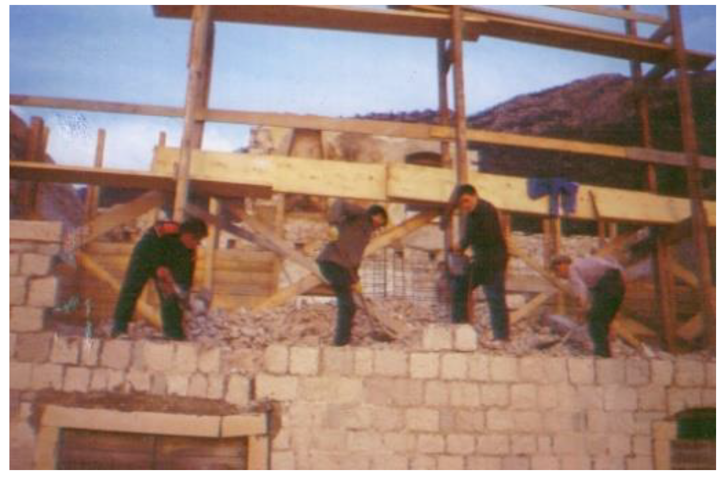
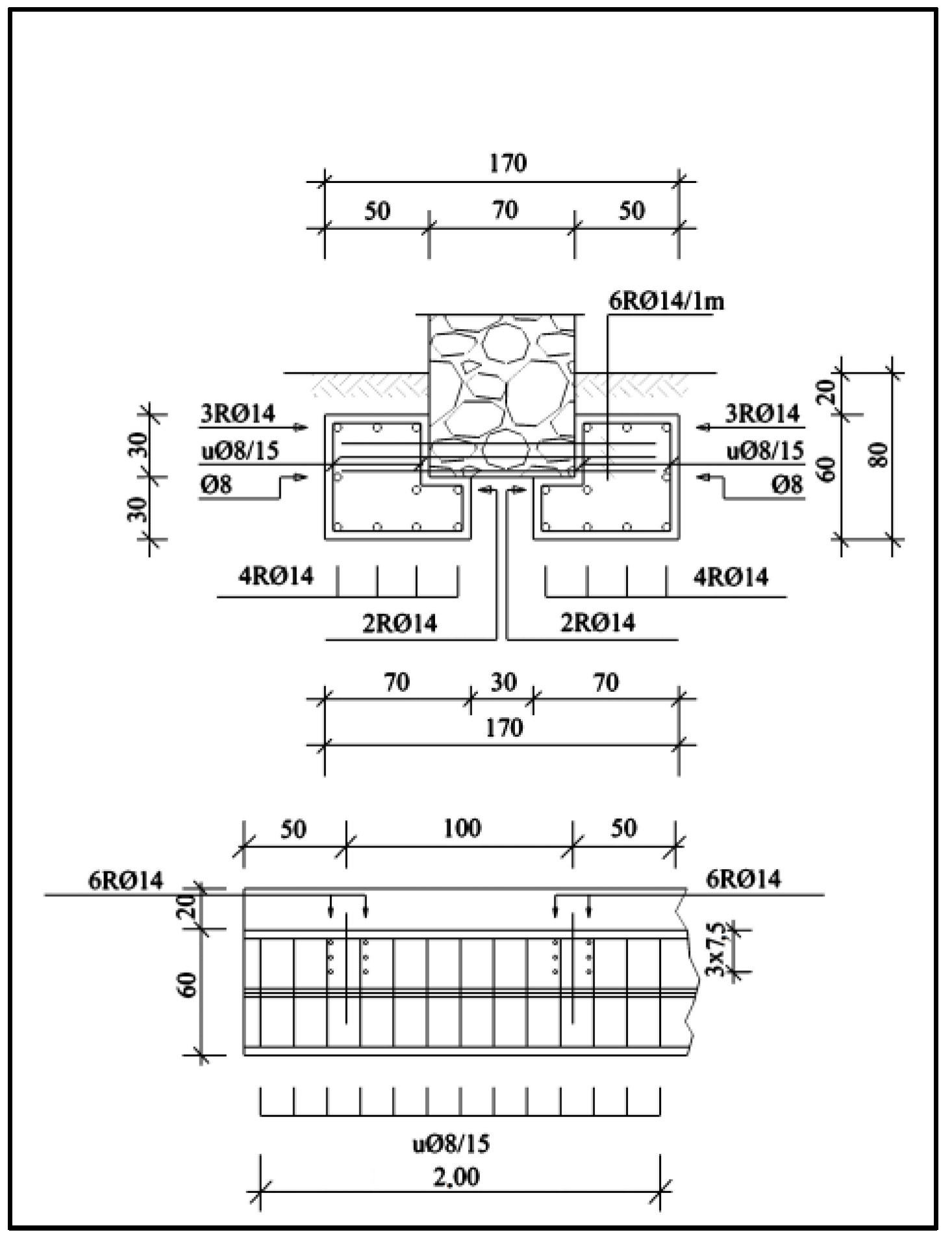
  • Rehabilitation and consolidation of the foundation—achieved by concrete underpinning of the foundation, reinforcing the soil by jet injection (Jet Grouting), repairing the foundation by inserting micropiles, repairing the foundation with expanding mixtures;
  • Joining walls and floor construction—structural walls should be evenly distributed in two orthogonal directions of the building and adequately connected. Their strength should be sufficient to successfully resist the expected seismic loads. Floor structures should be anchored to the walls and their rigidity should enable the distribution of seismic loads on the walls. This will preserve the integrity of the structure and prevent excessive oscillation of wall surfaces during earthquakes;
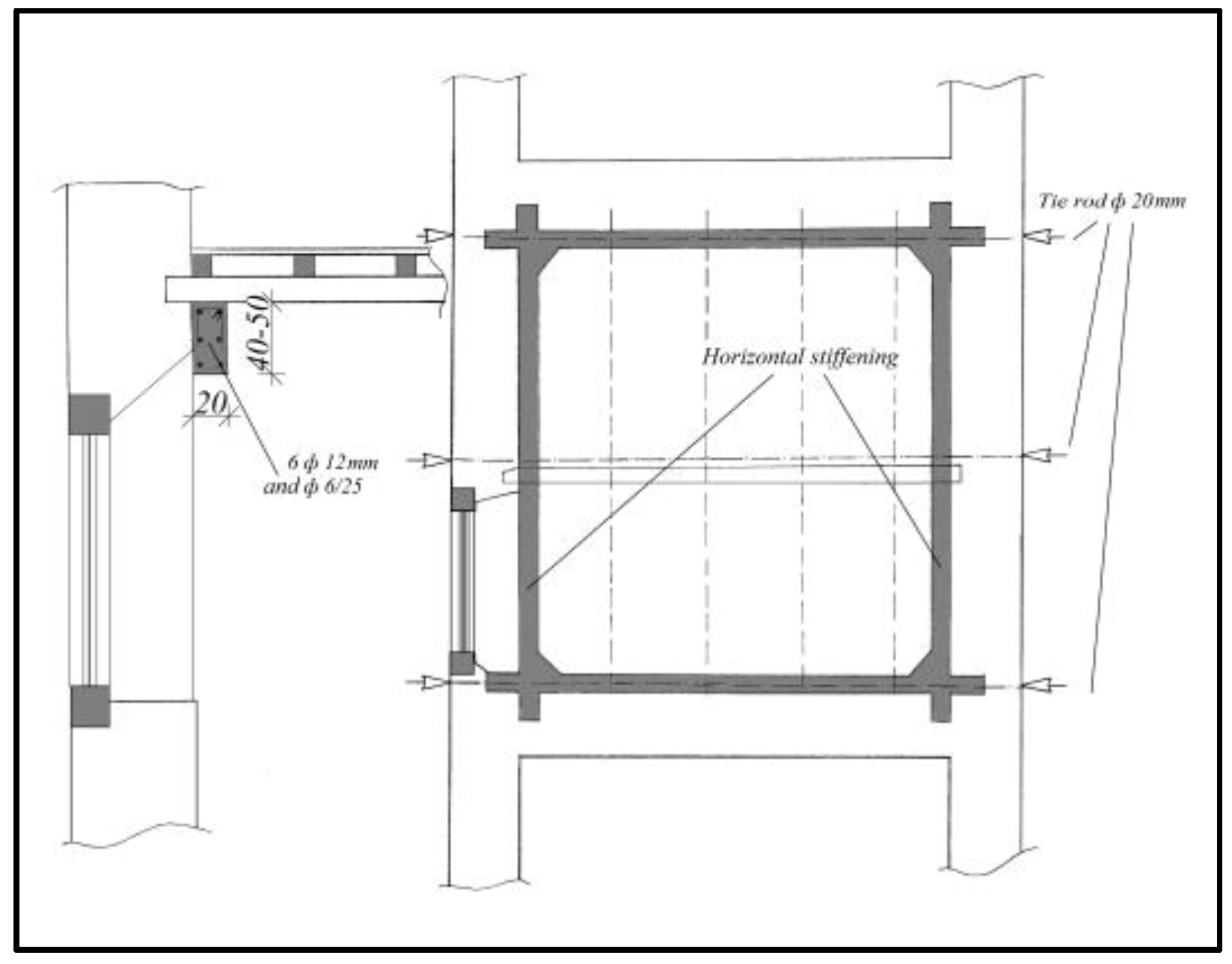
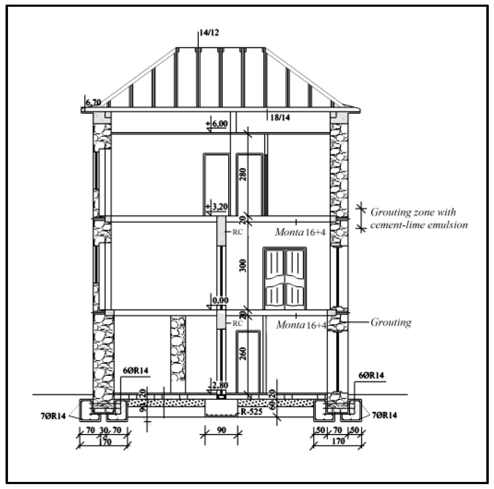
  • Reinforcement of walls—walls made of bricks, various types of blocks and stones are strengthened by injecting emulsions into cracks to restore the continuity between the brick and the existing mortar by permeating the cavities in the wall. The choice of material to be used as grout depends on the type of wall, its texture and is closely related to the efficiency of the grouting technique chosen: by coating the walls on one or both sides with reinforcement and 3 to 5 cm thick, MB 30 cement mortar, with the reinforcement anchored to a previously cleaned wall having open joints and cracks that are filled in the entire depth of the wall; by inserting vertical and horizontal ring beams with grout injection; by prestressing the walls with prior injection of cement emulsion into cracks; if the existing floor structures do not connect the load-bearing walls and do not have the necessary rigidity, reinforcement is performed by introducing steel clamps on both sides of the walls (for wooden floor structures); if the walls are made of stone, they are injected at the ceiling level, at the height of a minimum 60 cm. If the walls are damaged and dislocated, they must be rebuilt with the same material of a better quality, or they must be reinforced with ring beams;
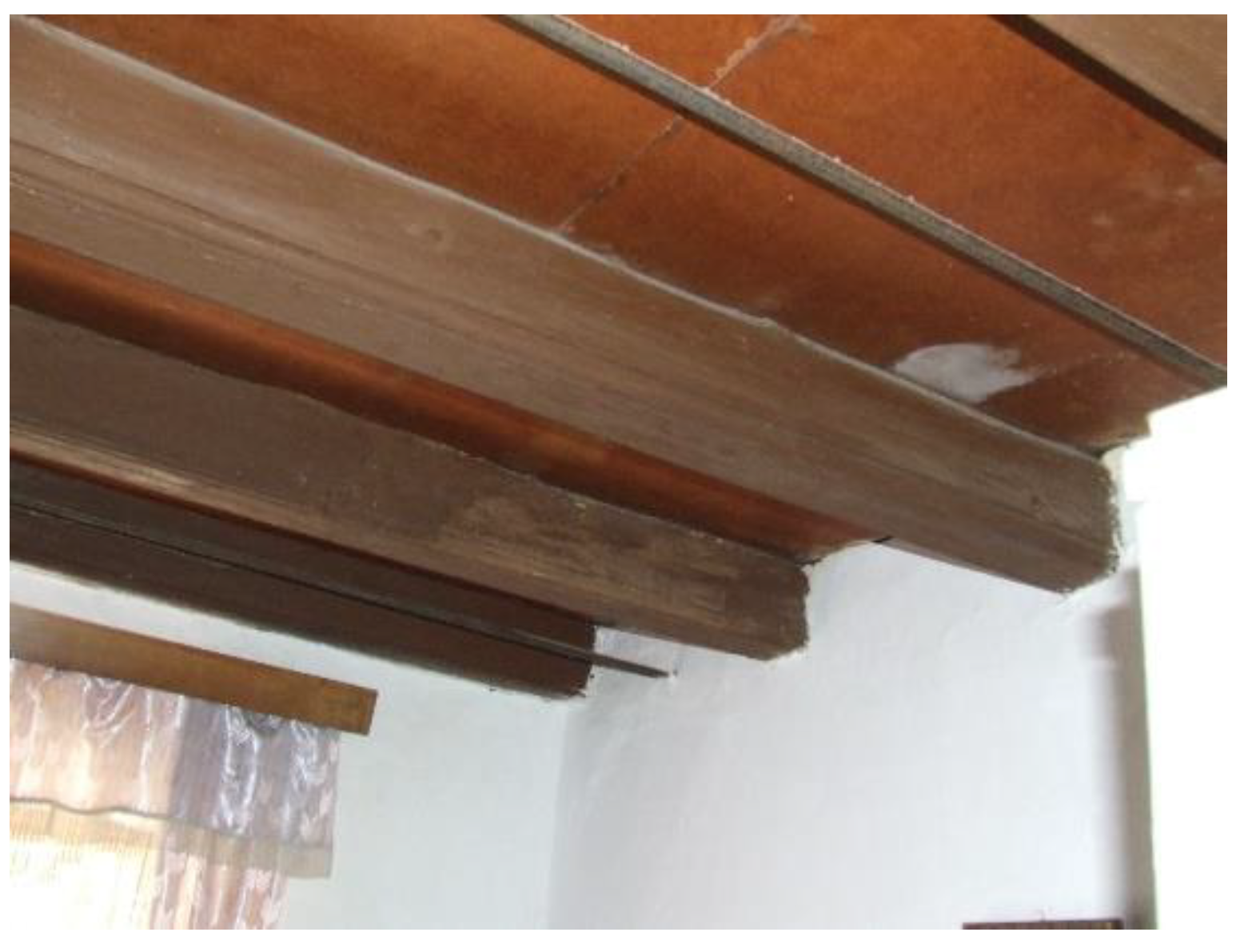
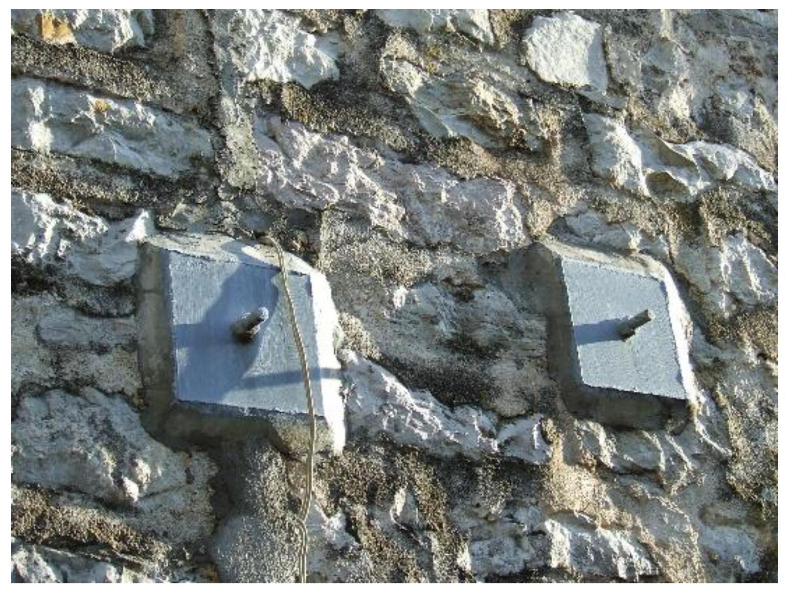
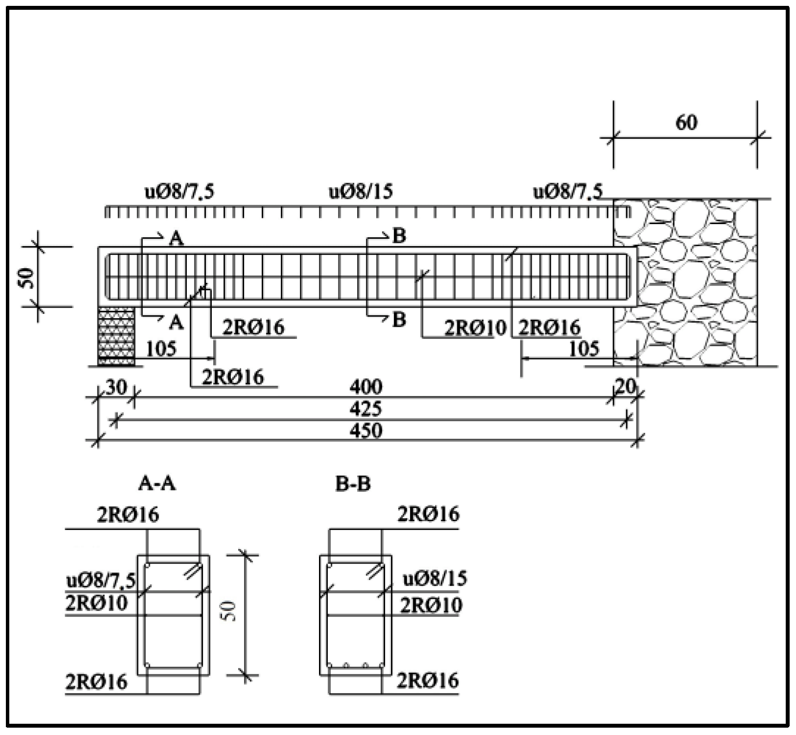
  • Reinforcement of floor structures—this is done by installing diagonal tie-beams if the floor structures are made of wood, along with anchoring of wooden beams into the walls. The layout and dimensions of the tie-beams are determined by calculation, while in one-story buildings the tie-beams are arranged in the course of the construction, without calculations, by replacing the dilapidated wooden floor structure with a reinforced concrete ceiling, whereas the adjoining between the ceiling and all load-bearing walls is achieved by cutting into the walls at the length of minimum 1.5 m.
  • Renovation of wooden roof structure, repair and reinforcement of nonstructural elements.
In practice, there are various types of protection methods, from those that require strict adherence to traditional crafts and techniques, to those that introduce completely new materials and structural systems [17,18,19].
In the last period, in order to preserve the stylistic whole of a building and the longevity of a compound (old–new) construction, attention is increasingly being paid to introducing the least problematic and a high-quality combination of old and new materials. Epoxy-based materials are used most commonly. When using these materials, it is necessary to assess the compatibility of physical/mechanical properties (density, linear thermal expansion) of the bonding material and the bonded material, the volume of the bonding material, the size of the joint being filled in, and the temperature around the joint to prevent straining between the resin and the surrounding structures [20].
A significant novelty is the emergence and use of fibre-reinforced polymers (FRP). Their development was very fast, from twisted fibres to fabrics of practically unlimited dimensions. The use of FRP fibres is almost irreplaceable in the restoration of cultural goods from the consequences of earthquakes [21]. Reinforcement of masonry structures using FRP products, compared to traditional reinforcement techniques, has the following advantages:
  • little or no extra weight;
  • fast and noninvasive application that does not cause changes in the appearance of the building and does not interfere with its use during the performing of reinforcement;
  • significant increases in stress resistance;
  • the ability to avoid the mechanism fracture by cracking.
One of the directions in the reconstruction of the architectural heritage after an earthquake is the use of old, traditional materials significantly improved by new technologies. Their application in reconstruction of architectural heritage enables the implementation of one of the basic principles of conservation—reversibility. Similar to the improved old materials, the completely new nano materials enable delicate interventions that maximally preserve the original tissue of the buildings that remained undamaged or slightly damaged in earthquakes.

5.2. Reconstruction Levels and Overview of Proposed Measures

Based on the knowledge of the basic principles of design and behaviour of buildings during earthquakes, it is necessary to make a decision on technical measures and methods for rehabilitation by increasing the seismic resistance of a particular facility. Which measures and methods will be applied depends on the configuration of a particular building, the type and quality of the material used and the degree of damage, as well as the level of seismic resistance to be achieved. The final decision on the manner of rehabilitation and strengthening of the facility should always be based on the calculations and decisions of the engineers (in agreement with experts for the protection of cultural monuments), as well as on data related to the recorded condition of the facility, including its damage. It should also be based on the data on the types and quality of materials of which its load-bearing structure is made.
Given the degree of damage, three levels of reconstruction have been suggested. For each of the levels of reconstruction and rehabilitation, a basic description of the measures and necessary interventions is presented [22]. Each of the suggested levels has its own specific characteristics reflected in the details. The main goal is for each of the levels, and the reconstruction and rehabilitation process to be the least invasive and as most cost-effective as possible, with the use of light materials and simple techniques. By applying a higher level or a combination of several levels at the same time, the earthquake resistance of the building as a whole grows.
Depending on the applied level of reconstruction and rehabilitation, the cost of reconstruction itself increases, which is correlated and is proportional to the increase in the level of earthquake resistance of the existing facility.

5.2.1. Level 1

The main goal of Level 1 is to return the existing building to its original state, that is, to its condition before the earthquake, with additional improvement of those parts of the building that have shown particular earthquake vulnerability. It is necessary to restore the building for living and use, which includes minimal reinforcements with classical methods that do not significantly interfere with the living space and construction. The goal is primarily to connect the free walls, but also to connect the structure [22].
This level of reconstruction and rehabilitation is divided into five basic measures that are applicable without a detailed structural analysis (manual calculations of individual elements are possible) and global analysis of the building:
  • Repair of observed cracks and damage to gable walls and chimneys (filling them with mortar and securing them with FRP protection)
  • Repair and stabilization of the roof structure and roof covering
  • Connecting the floor structure and gable walls
  • Local reinforcements of walls (grouting and filling the cracks), lintels and window sills
  • Connecting the walls
The estimated value of works undertaken at this level is 90–95 Euro/m2 [22].

5.2.2. Level 2

At Level 2, additional interventions are being made in relation to Level 1, with the main goal to strengthen the existing building so as to improve the earthquake resistance of the building in relation to its resistance that it had before the earthquake and to amount at least 50% of that resistance required for new facilities.
The basic precondition for carrying out the reconstruction works on Level 2 is that the necessary works listed in Level 1 were taken before.
At this level, it is necessary for an authorized expert (structural engineer) to perform a simple global analysis of the entire facility and make a static calculation of the observed critical places of individual elements that were damaged in the earthquake and in need for rehabilitation. Reinforcements of damaged elements with FRP products are most often taken. The measures taken do not change the stiffness and mass of the object.
From an economic point of view, Level 2 is economically the most profitable. The estimated value of works at this level is approximately 70 Euro/m2, and if the works are combined with works performed at Level 1, (depending on the scope of work taken) the estimated value of works is approximately 165 Euro/m2 [22].

5.2.3. Level 3

At Level 3, there is an additional increase in the resilience of the building in relation to Level 2, with the requirement to achieve 75–100% resistance to the effects of earthquakes related to new buildings. At this level, applied materials do not contribute to the increase of the total weight of the structure. A detailed global analysis of the structure and a detailed structural analysis are undertaken. Level 3 requires the preparation of project documentation at the level of the Project for construction and seismic classification of the facility. The application of this level conditions the eviction from the building because it requires far more extensive works. Level 3 is an upgrade of Level 2. The estimated value of works at this level is 230 Euro/m2, and if the works are combined with works performed at level 1 and level 2, the estimated value of works is about 400 Euro/m2 [22].
The cost of reconstruction and rehabilitation works depends on the type and amount of work to be taken. In the following text, for each of the suggested levels, an estimate of the cost of work is given, based on previous experience in performing these types of rehabilitation works.
All levels of renovation are designed to preserve the authenticity of the building as much as possible, without interfering with its functionality. By applying these levels, the structural assembly, purpose or surface of the space does not change. Each of the proposed levels can be done separately, with a time distance from the previous level.
In case all three proposed levels are implemented, it is possible to achieve savings ranging up to 15% compared to the case where each level is done partially.

6. Structural Restoration—Techniques

The examples of the two historical buildings in Lepetani, originating from the 19th century, demonstrated the two most common techniques of structural restoration applied by the end of the 20th century:
  • Structural restoration—noninvasive technique
  • Structural restoration—invasive technique

6.1. Structural Restoration—Noninvasive Technique

Using the regulations for eliminating the consequences of the catastrophic earthquake, the practice and suggestions of the Institute for the Protection of Cultural Monuments, a schematic drawing of the most basic restoration works done in the first half of the 1980s of the 20th century, number of floors being the ground floor, plus two floor levels, dating from the second half of the 19th century (Figure 21).
The rehabilitation of this building included measures proposed under Level 2, Section 5.2.
When making a sketch for the rehabilitation of a particular object, at the request of the investor, the following conditions were taken into account:
  • that the concept of the building does not change during the rehabilitation interventions
  • to keep the architectural appearance of the building authentic
  • to keep investment costs as low as possible.
An on-site inspection and a recording of the existing condition showed that the building constructively has two parts and that it rests on the adjacent building without a requisite expansion wall.
The walls are made of crushed stone with a suitable facade of bush hammered squares. The floor constructions are made of wooden beams with a grid of ordinary boards and a ceiling made of slats, reed and mortar (Figure 22). Except for the stone partition wall on the ground floor, the others are made of boards, slats and mortar (nonload-bearing walls). The roof is partly covered with a gutter and partly with clay pantiles.
The tightening of the building, which shows smaller cracks in the stone walls and does not indicate any major damage, was done with steel bars Φ20 mm, anchored to the fitting steel 10 mm thick plates or transverse reinforced concrete beams, to ensure its durability (Figure 23).
Reinforced tie-beam profile is requisite, because the walls are planned to be tightened only from the inside, so that the exterior facade does not deteriorate.
Reinforced concrete beams for stiffening are made next to the existing walls in the area above the inner door to the ceiling. In the height of the existing roof cornice, a reinforced concrete ring beam with a new cornice was made, connected with transverse beams for stiffness (without dismantling the roof structure).
Detailed description of these works is given below in the section with attached drawings (Figure 24, Figure 25 and Figure 26).

6.2. Structural Restoration—Invasive Technique

On the captain’s house dating from 1842, which has not been in function since 1979, the reconstruction and revitalization of this facility was done in the period from 2001–2003.
(Levels 1–3 of measures proposed and costs can be found in Section 5.2)
The condition of the building before the beginning of the reconstruction was that effectively the only thing left of the building was the outer walls (Figure 27, Figure 28, Figure 29 and Figure 30). They were also damaged, especially the front wall with a visionary and a height of 9 m. The walls were made of carved or ashlar stone blocks with a filling of small stone (lat. sauornam) [23]. Mortar joints generally represent “weak spots” in the wall, especially when poor quality mortar is used for masonry [24]. Traditional construction knows different types of lime mortars: with the addition of old oils, crushed bricks, red earth (Italian terra rossa), and so on [25].
Since the house suffered visible damage in the 1979 earthquake (Figure 31 and Figure 32), the rehabilitation is based on the reconstruction of vital load-bearing elements. Thus, the rigidity of the building is ensured by a pair of central massive RC canvases, which, with their continuity, close the entire building in height, with the peculiarity of structurally justified 50% reduction of cross-sectional areas of the canvas at the attic level. The RC canvases have been fixed so that their edging pillar width side would be entered into the stone façades, achieving the effective compound of the new and the existing old structure. In parallel with the RC canvases, from the foundation, that is, the bases of the ground floor, RC pillars extend vertically, ending at the level the first of the two attic RC ring beams. The cement mortar was injected into the cracked walls, followed by pointing. The disposition of the calculated seismic load implied the IX-degree effect on the MCS scale.
The existing strip foundations of the massive facade stone walls obtained a substantial RC reinforcement in the form of longitudinal L profile beams, which expanded the compact foundation surface, significantly increasing their rigidity (Figure 33).
The floor constructions of the floor and the attic are solved with LMT ceilings that cover the entire surface of the foundations, ending with an anchor RC wreath, clamped in the massive facade walls (Figure 34 and Figure 35). At this junction, cement emulsion injection was essential.
The dispositional solution of the roof structure, as well as the arrangement of the partition walls of the attic space, urged the construction intervention at the level of the floor structure at the attic (Figure 36). The roof essentially consists of two hipped roofs placed one on top of the other. The lower, larger, covers the dimensions of the house, while the other is placed transversely to it above the central superstructure.
A pair of continuous RC suspended beams were constructed, having the function of the load-bearing base of the side walls of the attic belvedere structure, as well as the associated RC pillars with another attic cornice. The mentioned RC pillars, as well as the previous ones in the lower floors, are clamped in massive facade stone walls. A typical roof structure consists of construction elements made of second-class coniferous wood. The roof is made with thermal and waterproofing provided for a given climate zone.
All RC elements are made of concrete MB30, reinforcement RA400/500 (columns and beams, as well as reinforcement of floor beams GA240/360 (stirrups), MA500/560 (RC canvases, and in situ components. Criteria for aseismic design formed for new buildings today, were applied to this building (Figure 37 and Figure 38) [26].

7. Conclusions

Monuments and historical buildings of the Bay of Kotor and a wider surrounding area have by rule been masonry, massive, nonframe, made of stone and as the basic building material and lime mortar as a binder. Such an authentic construction form, their elements and building techniques have shown a number of shortages, with high structures being highly undesirable from the aspect of the aseismic requirements. In the 1979 earthquake, many buildings of both the profane and sacral architecture in the Bay of Kotor suffered the same fate as the one shown in the picture. For the same earthquake intensity, higher damage was generally observed for monuments rather than historical buildings.
The most frequent and important structural problems to be solved in rehabilitation of buildings in the Bay of Kotor by subsidence or by earthquakes are those related to avoiding overturning or excessive inclination of walls and columns and, consequently, collapse of roofs and floors they are supporting. The most common solution in the past few decades has been by placing reinforced concrete ring beams at the top of walls, the purpose of which is to distribute load concentrations and to connect and to provide some confinement for the whole set of load-bearing walls. In intermediate floors a similar function has been assigned to beams surrounding concrete slabs constituting horizontal diaphragms. Frequently, connection between concrete beams and masonry walls has not been properly solved, thus impairing the efficiency of the solution; moreover, no proper care has been taken regarding the durability of the concrete work.
External tie-bars anchored to walls are more widely accepted by conservationists than ring beams and are becoming the most common measure to absorb lateral thrust. Common steel bars are used for external ties, whereas stainless steel is generally used when bars are embedded in masonry. Welded wire meshes with a concrete mortar rendering over the masonry walls were rather common in the recent past for strengthening and connecting masonry walls. The same could be said about arrays of steel anchors embedded in masonry. For pillars, grout injections and replacement of degraded mortars and stones have been the most common procedures, in addition to confinement by external steel rings or plates. No application of new materials, as resins or high strength fibers, is known to have been performed in Montenegro.
Results show the need to better understand the seismic behaviour of this type of construction as well as to define more appropriate strategies to be applied. In general, architectural conservation guidelines (e.g., ICOMOS Charters) and guidelines for structural restoration (e.g., Eurocodes) usually lead to contradictory approaches to heritage conservation. On the one hand, architectural conservation guidelines follow the minimum intervention concept by which the applied interventions should be limited, reversible and should strive towards minimising the impact on the heritage substance. On the other hand, the aim of structural restoration is to maximise safety and resilience of the structure by using strengthening techniques which are often very invasive and irreversible [1].
The need to take preventive measures of structural strengthening to minimize damage or avoid any loss of immeasurable value is surely a priority. Such measures require a previous evaluation of the expected seismic response through modelling this representative type of building. The concern about structural safety with respect to seismic actions has led to the assessment of seismic vulnerability, which should be a priority in the mitigation of seismic risks, and the planning and development of strengthening intervention strategies that will ensure appropriate technical decisions and financial support [9].
Drawing upon past experiences, there is a hope that the seed of new philosophy of intervention for safety could develop: to use simple and “ancient” ideas, alternatives, translated into modern technologies and methods that should not be generalized, but rather developed each time for each individual case [27].
Measures to protect URM monuments and historical buildings would help preserve the architectural heritage in the Bay of Kotor, which has been endangered for the past 20 years. Thus, the unique cultural landscape would be preserved for future generations, together with the natural environment.

Author Contributions

Optimal design and writing, D.T.; analysis, L.M.; N.G.; I.R.; J.A.; three authors have equally contributed to writing the final version of the paper. T.T. translated the paper. All authors have read and agreed to the published version of the manuscript.

Funding

This research received no external funding.

Institutional Review Board Statement

Not applicable.

Informed Consent Statement

Not applicable.

Data Availability Statement

Not applicable.

Conflicts of Interest

The authors declare no conflict of interest.

References

  1. Petrovčič, V.; Kilar, V. Seismic rehabilitation of masonry heritage structures with base-isolation and with selected contemporary strenghthening measures. Int. J. Saf. Secur. Eng. 2017, 7, 475–485. [Google Scholar]
  2. Federal Emergency Management Agency. Repair of Earthquake Damaged Concrete and Masonry Wall Buildings; FEMA: Washington, DC, USA, 1998; p. 80.
  3. Federal Emergency Management Agency. Techniques for the Seismic Rehabilitation of Existing Buildings; FEMA: Washington, DC, USA, 2006; p. 571.
  4. Ruggieria, S.; Tosto, C.; Rosati, G.; Uva, G.; Ferro, G.A. Seismic Vulnerability Analysis of Masonry Churches in Piemonte after 2003 Valle Scrivia Earthquake: Post-event Screening and Situation 17 Years Later. Int. J. Archit. Herit. 2020, 1–29. [Google Scholar] [CrossRef]
  5. De Matteis, G.; Brando, G.; Corlito, V. Predictive model for seismic vulnerability assessment of churches based onthe 2009 L’Aquila earthquake. Bull. Earthq. Eng. 2019, 17, 4909–4936. [Google Scholar] [CrossRef]
  6. Lagomarsino, S.; Podestà, S. Damage and Vulnerability Assessment of Churches after the 2002 Molise, Italy, Earthquake. Earthquake Spectra 2004, 20, 271–283. [Google Scholar] [CrossRef]
  7. Valluzzi, M.R.; Binda, L.; Modena, C. Mechanical behaviour of historic masonry structures strengthened by bed joints structural repointing. Constr. Build. Mater. 2005, 19, 63–73. [Google Scholar] [CrossRef]
  8. Ilija, L. Svojstva istorijskih zidanih konstrukcija u seizmičkim zonama (primer Boke Kotorske). Izgradnja 2011, 11–12, 698–703. [Google Scholar]
  9. Vicente, R.; Rodrigues, H.; Varum, H.; Silva, R. Evaluation of Strengthening Techniques of Traditional Masonry Buildings: Case Study of a Four-Building Aggregate. J. Perform. Constr. Facil. 2011, 25, 202–216. [Google Scholar] [CrossRef] [Green Version]
  10. Binda, L.; Cardani, G.; Saisi, A.; Modena, C.; Valluzzi, M.R. Multilevel approach to the analysis of the historical buildings: Application to four centers in seismic area finalised to the evaluation of the repair and strengthening tech-niques. In Proceedings of the XIII International Brick and Block Masonry Conference, Amsterdam, The Netherlands, 4–7 July 2004. [Google Scholar]
  11. Borri, A.; De Maria, A. Eurocode 8 and italian code. A comparison about safety levels and classification of interventions on masonry existing buildings. In Proceedings of the Eurocode 8 Perspectives from the Italian Standpoint Workshop, Naples, Italy, 3 April 2009; pp. 237–246. [Google Scholar]
  12. Borri, A.; Cangi, G. Vulnerabilità ed interventi di prevenzione sismica nei centri storici umbri dell’alta Val Tiberina. In Proceedings of the XI Congresso Nazionale “L’ingegneria Sismica in Italia”, ANIDIS, Genoa, Italy, 25–29 January 2004. [Google Scholar]
  13. Tomanović, D.; Rajković, I.; Grbić, M.; Aleksić, J.; Gadžić, N.; Lukić, J.; Tomanović, T. Houses Based on Natural Stone; A Case Study—The Bay of Kotor (Montenegro). Sustainability 2019, 11, 3866. [Google Scholar] [CrossRef] [Green Version]
  14. Pollak, D. Ovisnost Inženjerskogeoloških Svojstava Karbonatnih Stijena o Njihovim Sedimentno-Petrološkim Značajkama (Trasa Jadranske Autoceste: «Tunel sv. Rok–Maslenica»). Master’s Thesis, Sveučilište u Zagrebu-Rudars-Geološko-Naftni Fakultet, Zagreb, Croatia, 2002. [Google Scholar]
  15. Kurtović-Folić, N.; Folić, R. Some new experiences in built heritage restoration. In Proceedings of the International Scientific Conference BASA’2019, Sofia, Bulgaria, 21–23 November 2019; Tuleškov, N., Partov, D., Eds.; Bulgarian Academy of Sciences and Art: Sofia, Bulgaria, 2019; pp. 31–46. [Google Scholar]
  16. Kurtović-Folić, N.; Folić, R. Past and some topical problems of built heritage protection from earthquaqes. Build. Mater. 2020, 63, 27–67. [Google Scholar]
  17. Žarnić, R. Technologies for Safeguarding of Heritage Buildings in Slovenia. Faculty of Civil and Geodetic Engineering, University of Ljubljana. pp. 1–13. Available online: http://docplayer.net/11578156 (accessed on 25 January 2021).
  18. Barou, L.; Oikonomopoulos, F.; Bristogianni, T.; Veer, F.A.; Nijsse, R. Structural glass: A new remedial tool for the consolidation of historic structures. Heron 2018, 63, 159–198. [Google Scholar]
  19. Branco, M.; Guerreiro, L.M. Seismic rehabilitation of historical masonry buildings. Eng. Struct. 2011, 33, 1626–1634. [Google Scholar] [CrossRef]
  20. De Canio, G. Marble Device for the Basic Isolation of the Two Bronzes of Riace: A proposal for the David of Michelangelo. In Proceedings of the 15th World Conference on Earthquake Engineering, Lisboa, Portugal, 24–28 September 2012; pp. 1–10. [Google Scholar]
  21. Sidraba, I. New Materials of Stone Monuments in Latvia; Institute of Silicate Materials, Riga Technical University: Riga, Latvia, 2001; pp. 1–13. [Google Scholar]
  22. De Lorenzis, L.; Nanni, A. International Workshop on Presentation of Historical Structures with FRP Composites, Final Report; National Science Foundation (NSF): Arlington, VA, USA, 2004.
  23. Galić, J.; Vukić, H.; Andrić, D.; Stepinac, L. Priručnik za Protupotresnu Obnovu Postojećih Zidanih Zgrada; Arhitektonski Fakultet: Zagreb, Croatia, 2020. [Google Scholar]
  24. Lalošević, I. Kostanjica—Prirodno i Kulturno Nasljeđe; Centralna Narodna Biblioteka Crne Gore: Cetinje, Montenegro, 2009; p. 26. [Google Scholar]
  25. Radonjanin, V. Sanacija i Ojačanje Zidanih Zgrada Oštećenih Usled Dejstva Zemljotresa. Izgradnja 2011, 5–6, 267. [Google Scholar]
  26. Đurovic, V. O malterima na zgradama od 16.do 19.veka u Boki Kotorskoj. Zbornik Zaštite Spomenika Kulture 1955, 6–7, 79–89. [Google Scholar]
  27. Dowrick, D.J. Earthquake Resistant Design, A Manual for Engineers and Architects; John Wiley & Sons: London, UK, 1977. [Google Scholar]
  28. Cusano, C.; Cennamo, C. Criteria for Optimizing Structural Safety through the Principles of Environmental Compatibility; IFAU Department of Architecture and Industrial Design, University of Campania “Luigi Vanvitelli”: Aversa, Italy, 2019. [Google Scholar]
Figure 1. Colapse of row houses in urban environment (Kotor).
Applsci 11 03544 g001
Figure 2. Openings in the walls (doors, windows) showed their vulnerability in the 1979 earthquake.
Applsci 11 03544 g002
Figure 3. (a) Cathedral of St. Tryphon—Romanesque bells collapsed in the 1667 earthquake. (b) The cathedral was designed as the three-aisled basilica.
Applsci 11 03544 g003
Figure 4. Church of St. Luke from the 12th century—cross-in-square plan.
Applsci 11 03544 g004
Figure 5. Cross-section of the Church of St. Luke.
Applsci 11 03544 g005
Figure 6. Church of St. Mary of the River from the 13th century.
Applsci 11 03544 g006
Figure 7. The Church of St. Mary dome is more solidly attached with the substructures, walls and lateral and transverse arches than the Cathedral of St. Tryphon.
Applsci 11 03544 g007
Figure 8. Cracking of belvedere structure in Prčanj and Stoliv.
Applsci 11 03544 g008
Figure 9. Cracking of belvedere structure in Prčanj and Stoliv.
Applsci 11 03544 g009
Figure 10. A row of houses in Prčanj and Muo.
Applsci 11 03544 g010
Figure 11. A row of houses in Prčanj and Muo.
Applsci 11 03544 g011
Figure 12. Stone wall with two sides.
Applsci 11 03544 g012
Figure 13. The corners of the house were constructed using extended blocks.
Applsci 11 03544 g013
Figure 14. Wooden floor constructions attached to the walls with anchors.
Applsci 11 03544 g014
Figure 15. Transversal beams had the function of tie-rods.
Applsci 11 03544 g015
Figure 16. Typical gable roof.
Applsci 11 03544 g016
Figure 17. Hipped roof construction.
Applsci 11 03544 g017
Figure 18. Verige and Kamenare quarries contain gray and red plate stones.
Applsci 11 03544 g018
Figure 19. Less regular shaped blocks on the lateral façade from Strp and Lipci quarries.
Applsci 11 03544 g019
Figure 20. Front façade walls were built using the highly regarded fine stone from Strp and Lipci quarries.
Applsci 11 03544 g020
Figure 21. A house in Lepetani from the second half of the 19th century whose rehabilitation was carried out in the 1980s of the 20th century.
Applsci 11 03544 g021
Figure 22. Posttensioning of the building was done using steel Φ20 mm rods.
Applsci 11 03544 g022
Figure 23. At their ends, the rods were anchored to the 10 mm thick steel plates.
Applsci 11 03544 g023
Figure 24. Cross-section—Positioning of tie-beams at each floor level.
Applsci 11 03544 g024
Figure 25. Version with interior ring beam fixed at the positions that suffered severe damage.
Applsci 11 03544 g025
Figure 26. Tie-beam position and reinforced concrete beams at the ground floor foundation.
Applsci 11 03544 g026
Figure 27. Captain’s house dating from 1842, before and at the beginning of reconstruction.
Applsci 11 03544 g027
Figure 28. Captain’s house dating from 1842, before and at the beginning of reconstruction.
Applsci 11 03544 g028
Figure 29. Captain’s house dating from 1842, before and at the beginning of reconstruction.
Applsci 11 03544 g029
Figure 30. Captain’s house dating from 1842, before and at the beginning of reconstruction.
Applsci 11 03544 g030
Figure 31. The façade had to be taken down due to the forced protrusion.
Applsci 11 03544 g031
Figure 32. The façade had to be taken down due to the forced protrusion.
Applsci 11 03544 g032
Figure 33. Reinforcement of façade wall foundations.
Applsci 11 03544 g033
Figure 34. Vertical cross-section of the building.
Applsci 11 03544 g034
Figure 35. Plan of floor attic reinforcing.
Applsci 11 03544 g035
Figure 36. RC cornices with stone slabs.
Applsci 11 03544 g036
Figure 37. West and East facade today.
Applsci 11 03544 g037
Figure 38. West and East facade today.
Applsci 11 03544 g038
Publisher’s Note: MDPI stays neutral with regard to jurisdictional claims in published maps and institutional affiliations.

