Abstract
The non-symmetrical collapse of an empty cylindrical cavity is modeled using Smoothed Particle Hydrodynamics. The presence of a nearby surface produces an anisotropic pressure field generating a high-velocity jet that hits the surface. The collapse follows a different dynamic based on the initial distance between the center of the cavity and the surface. When the distance is greater than the cavity radius (detached cavity) the surface is hit by traveling shock waves. When the distance is less than the cavity radius (attached cavity) the surface is directly hit by the jet and later by other shock waves generated in the last stages of the of the collapse. The results show that the surface is hit by a stronger shock when distance between the center of the cavity and the surface is zero while showing more complex double peaks behavior for other distances.
1. Introduction
Cavitation is a phenomenon occurring in a liquid that undergoes rapidly changes in pressure. At first a bubble, or cavity, nucleates and growth over a nucleation site. After growing up to maximum value, the cavity collapses generating shock waves [1].
When the pressure field in the liquid is isotropic, the cavity preserves its symmetry and the collapse has spherical symmetry [2,3,4]. However, when an anisotropic pressure field drives the collapse, the cavity does not preserve its symmetry and folds in a specific direction generating a high-velocity flow known as jet [1,5]. The anisotropic pressure field is generated by the so-called anisotropic driver, which also defines the jet folding direction [6]. The most common anisotropic drivers are rigid or free surface, gravity, presence of neighbor bubbles or a combination of the above. Another mechanism that makes a cavity folds during the collapse is the interaction with a shock waves that folds the cavity in the shock direction. This situation is known as shock-induced collapse, while the pressure driven collapse is called Rayleigh collapse [7,8].
From an engineering point of view, the high-speed jet generated in the Rayleigh collapse by the presence of a nearby solid surface is the scenario most addressed in the literature [8,9]. In fact, the high-speed flow can hit the surface causing erosion and eventually loss of material. This phenomenon, known as cavitation erosion, is undesirable in industrial, military and power station equipment such as pump impellers, high-speed propellers and turbine blades [10,11,12].
Thanks to its Lagrangian nature, Smoothed Particle Hydrodynamics (SPH) can handle problems with large deformations better than mesh-based technique [13] and, for this reason, it is particularly suited for studying cavitation. Joshi et al. [14] developed a Smoothed Particle Hydrodynamics axisymmetric solver to simulate a shock-induced collapse of an empty cavity and the erosion process of the nearby surface. Pineda et al. [15] used a SPH-ALE method to study a gas filled cylindrical cavity Rayleigh collapse far and near a surface. Nair and Tomar [16] used SPH to simulate an oscillating gas filled cylindrical cavity under a variable isotropic pressure field. Albano and Alexiadis [17] developed a SPH model to study the Rayleigh collapse of a gas filled cylindrical cavity that takes in account the heat diffusion at the gas-liquid interface. Among these studies, only Joshi et al. and Pineda et al. take in account anisotropic collapses. Joshi et al. only for the shock-induced collapse case, while Pineda at al only for cavity detached from the surface. Despite its importance in practical applications, non-symmetrical Rayleigh collapse of surface attached cavities, to the best of our knowledge, has never been investigated with the SPH method. Moreover, cavities commonly nucleate on surfaces rather than away from it [18,19,20]. This work, therefore, develops a SPH model for a non-symmetrical Rayleigh collapse of a cylindrical cavity which is considered the greatest causes of erosion and material loss [8,9].
2. Model
2.1. Smoothed Particle Hydrodynamics
Smoothed Particle Hydrodynamics is a mesh-free particle method originally developed by Gingold Monaghan [21] and Lucy [22] and used in a wide range of applications: astrophysics [23], shock waves [24,25,26,27], explosion [28,29,30], thermo-fluid flows [31], thermo-capillary flows [32], multiphase flow [33,34], Biological flows [35], non-Newtonian fluid flows [36,37].
Thanks to its particle nature SPH is part of the Discrete Multi-Physics framework where, coupled with other particle methods [38,39,40], is used to address multi-complex physics phenomena [41,42,43,44,45] to overcome the single weakness of each method.
The idea behind the SPH formulation lies in the integral representation of any continuum function depending on the three-dimensional position vector
where W is the smoothing function or kernel and h is the smoothing length. Dividing the domain in a finite number of computational particles with their own mass , is possible approximate any continuum function as
where , and are mass, density and position of the i-th particle. Equation (2) is known as particle approximation in SPH literature [13].
We used the SPH particle approximation to discretize continuity, momentum and energy conservation equation:
where is the velocity vector with , e internal energy and is the artificial viscosity introduced by Monaghan [24]. The Monaghan artificial viscosity depends on a constant parameter called dimensionless dissipation factor, , and from the speed of sound of particle i and j, and , with the following relationship.
To solve the set of Equations shown before, an Equation Of State (EOS) that links pressure P and density is required.
2.2. Computational Set Up
In this work, we focus on the non-symmetrical collapse induced by an anisotropic pressure field. The anisotropy is generated by non-symmetric water domain shown in Figure 1. The domain is divided in three concentric regions, delimited by three different radii. In each region, different types of computational particles are used:
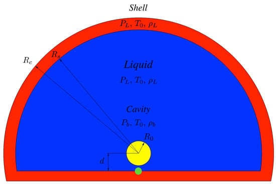
Figure 1.
Geometry of the simulation box.
- Cavity (): inside the yellow region in Figure 1, particles are removed to generate an empty cavity with .
- Liquid (): inside the blue region in Figure 1, particles are modeled as water following a liquid EOS. The density is set as [kg m] with initial pressure .
- Shell (): inside the red region of Figure 1, are modeled as in the liquid region. Moreover, they have fixed position and density to keep constant pressure as boundary condition. The extension of shell region has been discussed in previous work [17]. The lower part of this region also acts as a wall inducing anisotropy in the pressure field during the collapse.
The green region in Figure 1 does not refer to a different type of particle. We highlight it because, later, the pressure generated during the collapse will be monitored in the green region. As explained in next section, when a non-symmetric collapse is studied, it is necessary to quantify the anisotropy of the collapse. When the anisotropy is induced by the presence of a nearby solid surface, is common to use the stand-off, [6] defined as
where d is the distance between the cavity center and the wall (see Figure 1) and its initial radius. The dynamic of a cylindrical cavity in a Rayleigh collapse, where the driving force is the pressure difference between the pressure in the liquid, , and the pressure in the cavity, , is described by a 2D Rayleigh-Plesset (2DRP) equation [46]:
However, the 2DRP equation only describe the dynamic of a symmetrical collapse. Form our knowledge an equation to validate the dynamic of a non-symmetrical collapse has still to be developed. For this reason, as commonly done in the literature [15,17,46,47], the model presented as been validated for the case of symmetric collapse against Equation (6) [17].
In the simulations we use the Lucy Kernel [13] and the Tait EOS [13] with a smoothing length of where is the initial particle spacing. The dimensionless dissipation factor, time step and speed of sound were set as , [s] and [m s]. The sensitivity of the results to parameters such as the kernel function, EOS or h, was investigated in a previous publication for the case of symmetric collapse [17]. In the next section, the particle resolution for the specific case of non-symmetric collapse is discussed.
2.3. Software for Simulation, Visualization and Post-Process
The simulations were run with the open-source code simulator LAMMPS [48,49]. The visualization and data post-processing were generated with the open-source code OVITO [50].
3. Results
As mentioned in the introduction, collapsing cavities formed during cavitation generate high-pressure shock wave [1]. When the collapse occurs near a solid surface, the symmetry of the cavity is not preserved and this produces a high-velocity flow known as re-entrant jet [5,7,8]. The characteristics of the jet depend on (see Equation (5)). When , the jet hits the opposite side of the cavity generating a high-pressure shock wave that travels in the direction of the solid surface. When , the jet hits directly the solid surface generating a water hammer pressure [51,52] that causes erosion.
3.1. Preliminary Results
Four preliminary simulations with different particle resolutions have been carried out with , MPa and . These values are chosen to match those commonly used in computational studies [14,17,52]. Figure 2 shows the total collapse time and the max jet speed (defined as ) for the different resolutions. Particle resolution is specified as the ratio between the initial particle spacing and the initial cavity radius .
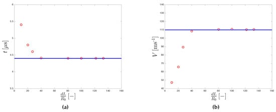
Figure 2.
Resolution convergences for collapse time (a) and max jet speed (b).
Both the collapsing time and max jet velocity converge for . This resolution value was also independently found by Joshi et al. and Pineda et al. At this resolution, the model correctly reproduces jet formation [5,7]. Figure 3 shows that as the collapse proceeds, wall proximity produces a pressure difference between the top and the bottom of the cavity. This pushes down the upper-side of the cavity inducing the formation of a high-velocity/low-pressure jet.
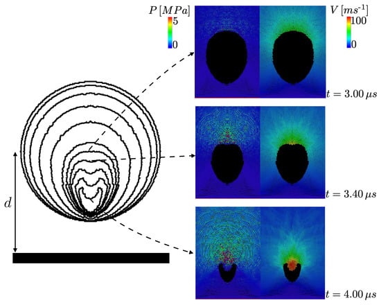
Figure 3.
Shape evolution with pressure and velocity field (, and MPa).
In Section 3.3 we show simulations at higher resolution. In fact, at higher resolutions, we will be able to uncover more details of the velocity pattern occurring during the collapse.
3.2. Stand-Off and Pressure Analysis
To study the effect of on the collapse, eight different stand-offs, in the range [0, 1.4], are simulated with 5 and 50 MPa. The upper limit was chosen since this study focuses on strongly deformed collapses, which are known to produce cavitation erosion [1,8]. In Figure 4, the dimensionless collapsing time and the maximal pressure at the wall are plotted for different . The dimensionless time is defined as the ratio between , the collapsing time obtained in the simulation for a given , and , the collapsing time for [17]. The dimensionless pressure is defined as the ratio between the maximal pressure at the wall and the characteristic pressure of a Rayleigh collapse [52]. The pressure at the wall is calculated at the green circle shown in Figure 1 positioned below the center of the cavity with a diameter of 0.01 mm.
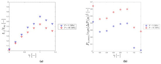
Figure 4.
Dimensionless collapse time (a) and dimensionless pressure (b) for different stand-off and pressure ().
The collapsing time shows a maximum for and a minimum for . When , the lower part of the cavity touches the wall, while the upper part is free to move (Figure 5c). During the collapse, the cavity loses its symmetry generating a re-entrant jet, which travels for the whole diameter of the cavity before reaching the surface. When the cavity reduces to a semi sphere. Therefore, the collapse is symmetric again (Figure 5h) and, in fact, (Figure 4a) as for [17].
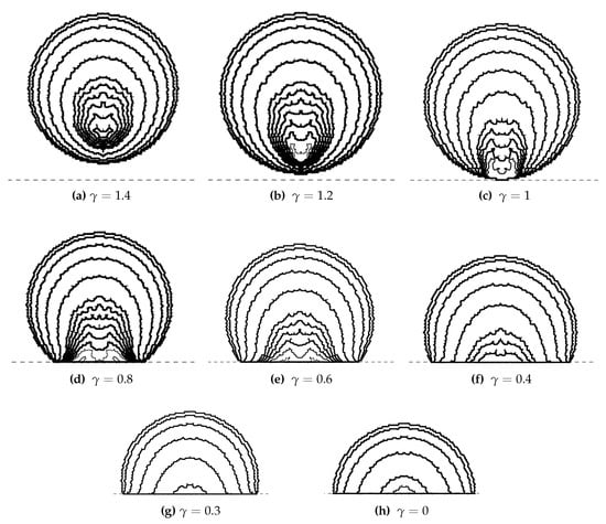
Figure 5.
Cavity shapes for different stand-offs ( and MPa). Each shape shows the cavity outline at a different time.
The pressure is shown in Figure 4b. The normalized maximum wall pressure is thought to scale with [1,6]. However, this was reported for values of , which are outside the range investigated in this study. Other studies show results similar to ours in the range of investigation [9,53].
3.3. Pressure and Speed Developed in High-Resolution Collapse
For 3 different stand-offs (0.0, 0.6 and 1.0), pressure histories at the center of the surface (i.e., green circle in Figure 1) are plotted in Figure 6.
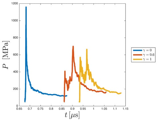
Figure 6.
Pressure trend for different stand-offs (=133 and MPa).
For , the pressure shows a single maximum of roughly 1200 MPa. This pressure is generated by a water hammer impact of the collapsing cavity on the surface. Since the symmetry is preserved, see Section 3.2, the collapse ends when the cavity impacts on the surface generating a high-pressure shock wave (Figure 7a). After the impact, the pressure at wall decreases as the shock moves into the liquid (Figure 7b,c).
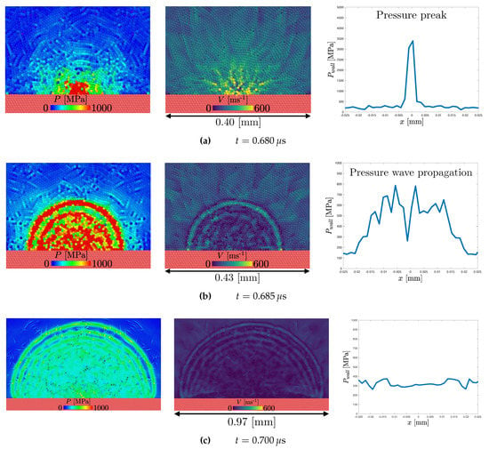
Figure 7.
Pressure and velocity field in the liquid and the spatial pressure trend at the wall ( = 133, and MPa).
When = 0.6 and 1 the pressure shows a double peak. As with , the first peak is generated by the water hammer impact of the cavity with the surface (Figure 8a and Figure 9a). After the impact, the jet splits into two high-speed/low-pressure lateral jets (Figure 8b) that will later impact with the sides of the cavity generating collapsing circles and a pair of “side” pressure waves (Figure 8c and Figure 9b).
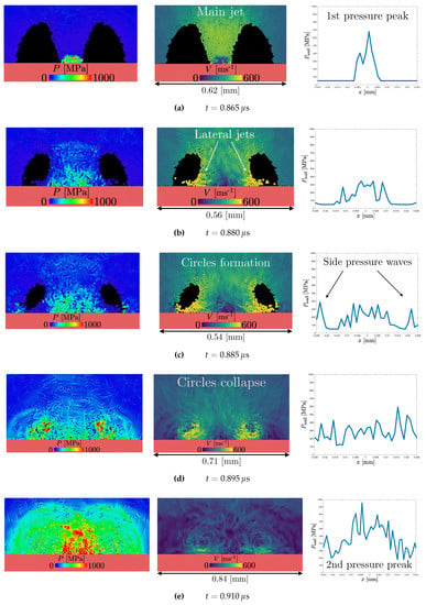
Figure 8.
Pressure and velocity field in the liquid and the spatial pressure trend at the wall ( = 133, and MPa).
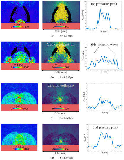
Figure 9.
Pressure and velocity field in the liquid and the spatial pressure trend at the wall ( = 133, and MPa).
The collapse ends when the fluid fills the circles. When this happens a third pair of pressure waves is generated (Figure 8d and Figure 9c). The waves will later merge at the center resulting in a second pressure peak (Figure 8e and Figure 9d). Figure 10 shows a schematic representation of a wall-attached cavity collapse with the three pairs shock formation for . It can be difficult to clearly identify these hydrodynamics patterns if the simulation is run at lower resolution (e.g., Joshi et al. 2019).
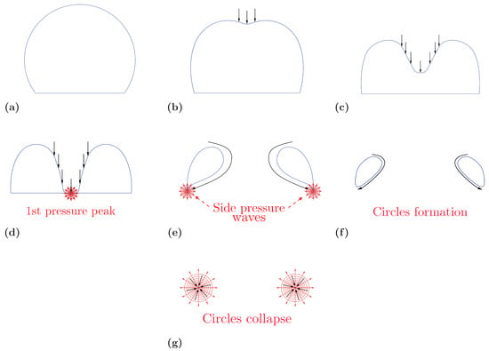
Figure 10.
Schematic representation of a wall-attached cavity collapse with the three pairs shock formation for . The blue lines represents the cavity, black arrows represent the liquid flow, red circles represent the shock waves propagation at different collapse stages.
As shown in Figure 6, when the first peak is higher compared to the first peak of . Before hitting the surface, the jet travels a longer distance for rather than . Therefore, it is accelerated by the pressure gradient for longer resulting in a higher water hammer pressure at the wall [8,51,54].
However, for the second peak, the behavior is reversed, and the peak is higher for . The water between the collapsing rings and the wall acts as a shield mitigating the shock wave [26,55]. When the distance between the rings and the wall is higher than resulting in a greater mitigation effect and lower pressure peak.
4. Conclusions
A SPH model is developed to study non-symmetrical Rayleigh collapse of an empty cylindrical cavity. When the cavity collapse near a solid surface the anisotropy of the pressure field induce the formation of the re-entrant jet. This anisotropy is quantified with the stand-off, .
Different collapses in the range are discussed showing that the model can correctly simulate the jet physics and the consequent pressure fields at the surface.
We study the collapse of attached cavities (), where the liquid exerts the maximum pressure over the surface. When the collapse is symmetric again and pressure shows a single max, which corresponds to the end cavity collapse. When the pressure shows multiple peaks, which reflect a more complex behavior with the circles’ formation and collapse.
This work shows the importance of studying the collapse of cavities attached to the surface. This case is less investigated than the detached collapse, but a better understanding of the final stages of the attached collapse is essential to improve predictions of cavitation erosion. For this reason, the simulations are run at higher resolution than previous studies. Only in this way, in fact, certain hydrodynamic features of the collapse can clearly emerge from the simulations.
Author Contributions
A.A. (Andrea Albano) and A.A. (Alessio Alexiadis) conceptualise the work; A.A. (Andrea Albano) designed the work and performed the simulations; A.A. (Andrea Albano) and A.A. (Alessio Alexiadis) contributed in writing–review and editing the paper. All authors have read and agreed to the published version of the manuscript.
Funding
This work was supported by the US Office of Naval Research Global (ONRG) under 256 NICOP Grant N62909-17-1-2051.
Conflicts of Interest
The authors declare no conflict of interest.
References
- Brennen, C.E. Cavitation and Bubble Dynamics; Cambridge University Press: Cambridge, UK, 2014. [Google Scholar]
- Rayleigh, L. VIII. On the pressure developed in a liquid during the collapse of a spherical cavity. Lond. Edinb. Dublin Philos. Mag. J. Sci. 1917, 34, 94–98. [Google Scholar] [CrossRef]
- Plesset, M.S. The dynamics of cavitation bubbles. J. Appl. Mech. 1949, 16, 277–282. [Google Scholar] [CrossRef]
- Hickling, R.; Plesset, M.S. Collapse and rebound of a spherical bubble in water. Phys. Fluids 1964, 7, 7–14. [Google Scholar] [CrossRef]
- Plesset, M.S.; Chapman, R.B. Collapse of an initially spherical vapour cavity in the neighbourhood of a solid boundary. J. Fluid Mech. 1971, 47, 283–290. [Google Scholar] [CrossRef]
- Supponen, O.; Obreschkow, D.; Tinguely, M.; Kobel, P.; Dorsaz, N.; Farhat, M. Scaling laws for jets of single cavitation bubbles. J. Fluid Mech. 2016, 802, 263–293. [Google Scholar] [CrossRef]
- Johnsen, E.; Colonius, T. Numerical simulations of non-spherical bubble collapse. J. Fluid Mech. 2009, 629, 231–262. [Google Scholar] [CrossRef]
- Kim, K.H.; Chahine, G.; Franc, J.P.; Karimi, A. Advanced Experimental and Numerical Techniques for Cavitation Erosion Prediction; Springer: Berlin, Germany, 2014; Volume 106. [Google Scholar]
- Philipp, A.; Lauterborn, W. Cavitation erosion by single laser-produced bubbles. J. Fluid Mech. 1998, 361, 75–116. [Google Scholar] [CrossRef]
- Knapp, R.; Daily, J.; Hammitt, F. Cavitation (Engineering Societies Monographs); McGraw-Hill: New York, NY, USA, 1970; Volume 39. [Google Scholar]
- Arndt, R.E. Cavitation in fluid machinery and hydraulic structures. Annu. Rev. Fluid Mech. 1981, 13, 273–326. [Google Scholar] [CrossRef]
- Giannadakis, E.; Gavaises, M.; Arcoumanis, C. Modelling of cavitation in diesel injector nozzles. J. Fluid Mech. 2008, 616, 153–193. [Google Scholar] [CrossRef]
- Liu, G.R.; Liu, M.B. Smoothed Particle Hydrodynamics: A Meshfree Particle Method; World Scientific: Singapore, 2003. [Google Scholar]
- Joshi, S.; Franc, J.P.; Ghigliotti, G.; Fivel, M. SPH modelling of a cavitation bubble collapse near an elasto-visco-plastic material. J. Mech. Phys. Solids 2019, 125, 420–439. [Google Scholar] [CrossRef]
- Pineda, S.; Marongiu, J.C.; Aubert, S.; Lance, M. Simulation of a gas bubble compression in water near a wall using the SPH-ALE method. Comput. Fluids 2019, 179, 459–475. [Google Scholar] [CrossRef]
- Nair, P.; Tomar, G. Simulations of gas-liquid compressible-incompressible systems using SPH. Comput. Fluids 2019, 179, 301–308. [Google Scholar] [CrossRef]
- Albano, A.; Alexiadis, A. A smoothed particle hydrodynamics study of the collapse for a cylindrical cavity. PLoS ONE 2020, 15, e0239830. [Google Scholar] [CrossRef]
- Pruppacher, H.R.; Klett, J.D. Microphysics of clouds and precipitation. Nature 1980, 284, 88. [Google Scholar] [CrossRef]
- Sear, R.P. Quantitative studies of crystal nucleation at constant supersaturation: Experimental data and models. CrystEngComm 2014, 16, 6506–6522. [Google Scholar] [CrossRef]
- Ferraro, G.; Jadhav, A.J.; Barigou, M. A Henry’s law method for generating bulk nanobubbles. Nanoscale 2020, 12, 15869–15879. [Google Scholar] [CrossRef]
- Gingold, R.A.; Monaghan, J.J. Smoothed particle hydrodynamics: Theory and application to non-spherical stars. Mon. Not. R. Astron. Soc. 1977, 181, 375–389. [Google Scholar] [CrossRef]
- Lucy, L.B. A numerical approach to the testing of the fission hypothesis. Astron. J. 1977, 82, 1013–1024. [Google Scholar] [CrossRef]
- Springel, V. Smoothed particle hydrodynamics in astrophysics. Annu. Rev. Astron. Astrophys. 2010, 48, 391–430. [Google Scholar] [CrossRef]
- Monaghan, J.; Gingold, R.A. Shock simulation by the particle method SPH. J. Comput. Phys. 1983, 52, 374–389. [Google Scholar] [CrossRef]
- Morris, J.; Monaghan, J. A switch to reduce SPH viscosity. J. Comput. Phys. 1997, 136, 41–50. [Google Scholar] [CrossRef]
- Liu, M.; Liu, G.; Lam, K. Investigations into water mitigation using a meshless particle method. Shock Waves 2002, 12, 181–195. [Google Scholar] [CrossRef]
- Albano, A.; Alexiadis, A. Interaction of Shock Waves with Discrete Gas Inhomogeneities: A Smoothed Particle Hydrodynamics Approach. Appl. Sci. 2019, 9, 5435. [Google Scholar] [CrossRef]
- Liu, M.; Liu, G.; Lam, K.; Zong, Z. Smoothed particle hydrodynamics for numerical simulation of underwater explosion. Comput. Mech. 2003, 30, 106–118. [Google Scholar] [CrossRef]
- Liu, M.; Liu, G.; Zong, Z.; Lam, K. Computer simulation of high explosive explosion using smoothed particle hydrodynamics methodology. Comput. Fluids 2003, 32, 305–322. [Google Scholar] [CrossRef]
- Sirotkin, F.V.; Yoh, J.J. A Smoothed Particle Hydrodynamics method with approximate Riemann solvers for simulation of strong explosions. Comput. Fluids 2013, 88, 418–429. [Google Scholar] [CrossRef]
- Ng, K.; Ng, Y.; Sheu, T.; Alexiadis, A. Assessment of Smoothed Particle Hydrodynamics (SPH) models for predicting wall heat transfer rate at complex boundary. Eng. Anal. Bound. Elem. 2020, 111, 195–205. [Google Scholar] [CrossRef]
- Hopp-Hirschler, M.; Shadloo, M.S.; Nieken, U. A smoothed particle hydrodynamics approach for thermo-capillary flows. Comput. Fluids 2018, 176, 1–19. [Google Scholar] [CrossRef]
- Shadloo, M.S.; Oger, G.; Le Touzé, D. Smoothed particle hydrodynamics method for fluid flows, towards industrial applications: Motivations, current state, and challenges. Comput. Fluids 2016, 136, 11–34. [Google Scholar] [CrossRef]
- Rahmat, A.; Yildiz, M. A multiphase ISPH method for simulation of droplet coalescence and electro-coalescence. Int. J. Multiph. Flow 2018, 105, 32–44. [Google Scholar] [CrossRef]
- Ye, T.; Pan, D.; Huang, C.; Liu, M. Smoothed particle hydrodynamics (SPH) for complex fluid flows: Recent developments in methodology and applications. Phys. Fluids 2019, 31, 011301. [Google Scholar]
- Shao, S.; Lo, E.Y. Incompressible SPH method for simulating Newtonian and non-Newtonian flows with a free surface. Adv. Water Resour. 2003, 26, 787–800. [Google Scholar] [CrossRef]
- Hosseini, S.; Manzari, M.; Hannani, S. A fully explicit three-step SPH algorithm for simulation of non-Newtonian fluid flow. Int. J. Numer. Methods Heat Fluid Flow 2007, 17, 715–735. [Google Scholar] [CrossRef]
- Pazdniakou, A.; Adler, P. Lattice spring models. Transp. Porous Media 2012, 93, 243–262. [Google Scholar] [CrossRef]
- Silling, S.A.; Epton, M.; Weckner, O.; Xu, J.; Askari, E. Peridynamic states and constitutive modeling. J. Elast. 2007, 88, 151–184. [Google Scholar] [CrossRef]
- Munjiza, A.A. The Combined Finite-Discrete Element Method; John Wiley & Sons: Hoboken, NJ, USA, 2004. [Google Scholar]
- Alexiadis, A. A smoothed particle hydrodynamics and coarse-grained molecular dynamics hybrid technique for modelling elastic particles and breakable capsules under various flow conditions. Int. J. Numer. Methods Eng. 2014, 100, 713–719. [Google Scholar] [CrossRef]
- Alexiadis, A. The discrete multi-hybrid system for the simulation of solid-liquid flows. PLoS ONE 2015, 10, e0124678. [Google Scholar] [CrossRef] [PubMed]
- Ariane, M.; Kassinos, S.; Velaga, S.; Alexiadis, A. Discrete multi-physics simulations of diffusive and convective mass transfer in boundary layers containing motile cilia in lungs. Comput. Biol. Med. 2018, 95, 34–42. [Google Scholar] [CrossRef]
- Rahmat, A.; Barigou, M.; Alexiadis, A. Numerical simulation of dissolution of solid particles in fluid flow using the SPH method. Int. J. Numer. Methods Heat Fluid Flow 2019. [Google Scholar] [CrossRef]
- Alexiadis, A. Deep multiphysics: Coupling discrete multiphysics with machine learning to attain self-learning in-silico models replicating human physiology. Artif. Intell. Med. 2019, 98, 27–34. [Google Scholar] [CrossRef]
- Chen, X. Simulation of 2D cavitation bubble growth under shear flow by lattice Boltzmann model. Commun. Comput. Phys. 2010, 7, 212. [Google Scholar] [CrossRef]
- Nasiri, H.; Jamalabadi, M.Y.A.; Sadeghi, R.; Safaei, M.R.; Nguyen, T.K.; Shadloo, M.S. A smoothed particle hydrodynamics approach for numerical simulation of nano-fluid flows. J. Therm. Anal. Calorim. 2019, 135, 1733–1741. [Google Scholar] [CrossRef]
- Plimpton, S. Fast Parallel Algorithms for Short-Range Molecular Dynamics; Technical Report; Sandia National Labs.: Albuquerque, NM, USA, 1993. [Google Scholar]
- Ganzenmüller, G.C.; Steinhauser, M.O.; Van Liedekerke, P.; Leuven, K.U. The Implementation of Smooth Particle Hydrodynamics in LAMMPS. 2011. Available online: https://www.gpusph.org/documentation/gpusph-setup.pdf (accessed on 13 April 2021).
- Stukowski, A. Visualization and analysis of atomistic simulation data with OVITO–the Open Visualization Tool. Model. Simul. Mater. Sci. Eng. 2009, 18, 015012. [Google Scholar] [CrossRef]
- Zhang, S.; Duncan, J.H.; Chahine, G.L. The final stage of the collapse of a cavitation bubble near a rigid wall. J. Fluid Mech. 1993, 257, 147–181. [Google Scholar] [CrossRef]
- Beig, S.; Aboulhasanzadeh, B.; Johnsen, E. Temperatures produced by inertially collapsing bubbles near rigid surfaces. J. Fluid Mech. 2018, 852, 105–125. [Google Scholar] [CrossRef]
- Tomita, Y.; Shima, A. Mechanisms of impulsive pressure generation and damage pit formation by bubble collapse. J. Fluid Mech. 1986, 169, 535–564. [Google Scholar] [CrossRef]
- Ghidaoui, M.S.; Zhao, M.; McInnis, D.A.; Axworthy, D.H. A review of water hammer theory and practice. Appl. Mech. Rev. 2005, 58, 49–76. [Google Scholar] [CrossRef]
- Malvar, L.J.; Tancreto, J.E. Analytical and Test Results for Water Mitigation of Explosion Effects; Technical Report; Naval Facilities Engineering Service Center Port: Hueneme, CA, USA, 1998. [Google Scholar]
Publisher’s Note: MDPI stays neutral with regard to jurisdictional claims in published maps and institutional affiliations. |
© 2021 by the authors. Licensee MDPI, Basel, Switzerland. This article is an open access article distributed under the terms and conditions of the Creative Commons Attribution (CC BY) license (https://creativecommons.org/licenses/by/4.0/).