Abstract
A new coupling method, immersed moving boundary–discrete element method–lattice Boltzmann method (IMB-DEM-LBM), is proposed to simulate particle flow for application in soil mechanics or coastal engineering. In this study, LBM fluid is simulated on the regular Eulerian grid and Lagrangian particle motion is governed by DEM while IMB couples the two algorithms. The new method is promising and robust as it resolves numerical instability near the particle boundary caused by mesh distortion in the conventional grid method. In IMB, the interface lattice solid fraction determines the distribution function ratio of non-equilibrium bounce back and Bhatnagar-Gross-Krook (BGK) collision. The non-equilibrium bounce back at moving boundary results in the fluid momentum change and contributes to the hydrodynamic force on particle. For numerical stability, this paper introduces the hydrodynamic force calculation concept from IB (immersed boundary method) to IMB, and at the same time, proposes a new solid fraction calculation method for sphere that divides the intersection into simple sector and triangle, as well as calculates the intersection area by vector. With this method, approximate inaccuracy is overcome while complicated integration is avoided.
1. Introduction
Particle flow exists in various fields, such as submarine granular flows, particle settlement, fluid beds combustion, motion of blood cells, and so on. However, capturing the micro-interaction of particles by experiment is difficult. Simulation is a remarkable technique that can well-represent a phenomenon or system. To acknowledge the hydrodynamic motion and collective behavior at grain scale, particle flow simulation is suggested.
Particle flow simulation with conventional finite element method (FEM) results in mesh distortion as the boundary of particles move. Arbitrary Lagrangian-Eulerian (ALE) and adaptive mesh refinement (AMR) techniques were proposed to reorganize the boundary grid [1]; however, FEM still suffers additional error in force coupling between fluid and particle. Since 1986, the Los Alamos lab has proposed the concept of discrete simulation of fluid dynamic [2]. A number of mesh-free methods such as smoothed particle hydrodynamics (SPH), material point method (MPM), and lattice Boltzmann method (LBM) were rapidly developed in recent years, which bypass the usual necessary grid, thereby avoiding mesh tangling and distortion.
LBM is widely used in hydrodynamic simulation, which replaces fluid macroscopic properties with distribution function, and progresses stream and collision on a background regular grid. Because moving boundary has an influence on background grid flag change, it is easy to simulate the fluid-structure interaction problem such as particle flow with a suitable coupling technique. There are two kinds of fluid-structure interaction boundaries for LBM: (a) stationary boundary, and (b) moving boundary. Ziegler [3] proposed a simple bounce back scheme of stationary boundary which turns the incident distribution function to the opposite direction. Filippova [4] first applied the lattice Boltzmann method to gas-particle flow, which allowed the flow to pass through fixed deposition of particles with irregular surface shape. For the moving boundary, three popular coupling methods exist: (a) modified bounce back method (MBB) [5], (b) immersed boundary method (IB) [6], and (c) immersed moving boundary method (IMB). In this paper, particle motion is governed by discrete element method (DEM), which is coupled with lattice Boltzmann method (LBM) to simulate particle flow.
Ladd [5] proposed MBB-LBM, introducing an additional term to the collision operator, causing momentum change of particle’s neighbor fluid lattice, which then causes a reaction force on particle (hydrodynamic force) as a result of momentum change of fluid. When the boundary interface chain is not in the lattice center, the streaming point is not on the lattice. As a result, Bouzidi et al. [7] proposed a method of calculating the streaming point distribution function by spatial interpolation. Yu et al. [8] stated that momentum exchange only happens between solid interface and fluid lattice, and that force calculation only depends on neighbor fluid lattice. Soundararajan [9] combined DEM with MBB-LBM for landside simulation. In addition, Bonaccorso et al. [10] studied the rheology of bijel nano particle in confined flow. The drawback of MBB-LBM is the discontinuance of flag change of lattice, which causes complex interpolation, and fluctuation in population updating and hydrodynamic force on particle, which increases programming difficulty.
Peskin [11] suggested the immersed boundary method to simulate flow membranes interaction by using a spring between different interface chain node, and by interpolating chain node velocity from neighbor fluid lattice. Calculation of the restoring force depended on the chain node’s relative displacement by Hooke’s law, and the reaction boundary body force on fluid is obtained by interpolation of restoring force of boundary. Feng and Michaelides [12] combined IB and LBM to simulate the fluid-structure interaction (FSI) problem. IB-LBM was then extended to more FSI problems such as symmetric flapping wing movement simulation [13], deformable particles [14], and multicomponent flow spinodal decomposition [15]. However, IB discretized delta function interpolation can be inaccurate [16], and complicated simulations using IB can result in computational expense [6]. In addition, coupling of IB-LBM is not compatible to the parallel nature of LBM [17].
Immersed moving boundary was proposed by Noble [18]. Cook et al. [19] then coupled LBM and DEM to simulate particle flow together with IMB. Interface lattice distribution function collision is associated with solid fraction, and momentum exchange on the particle boundary is introduced to calculate the hydrodynamic force reaction on the particle. The IMB is easy to code, and is compatible with the parallel nature of LBM. In addition, the hydrodynamic force based on accurate physical description can be easily obtained using IMB. Since solid fraction is a critical variable for hydrodynamic force calculation, several papers have focused on accurate solid fraction calculation algorithm. Owen et al. [20] decomposed the lattice cell into subcells with cell size , marking subcells’ flag as solid if their centers are located within the particle radius domain. Solid fraction is calculated as the sum of all the solid subcells in the corresponding interface cell lattice. Galindo-Torres [21] proposed an edge–intersection averaging method, which calculates the intersection length of particle and interface lattice cell edge, and estimates the solid fraction of interface lattice with ratio of total interaction length and all edges length. However, edge–intersection averaging is less accurate, adding further interaction points to reconstruct convex hull [22], and solid fraction calculation depends on convex hull area. Jones and Williams [23] calculated solid fraction directly from volume integral, which is a linear expression about particle radius. However, the method only works on four and three edges interaction cases.
Based on all of the previous mentioned algorithms, this paper proposes an accurate, understandable, and easy to code solid fraction calculation scheme for sphere particles, which is highly feasible for all kinds of interaction modes. In the present paper, the IMB-DEM-LBM, which is easy to extend to multi-particle flow, is applied to simulate the settlement and collision of two rigid particles, improving the numerical stability of solid fraction calculation. The paper is organized as follows: Section 2, Section 3, Section 4 present the theory of LBM, DEM, and IMB, respectively, while Section 5 illustrates the new solid fraction algorithm; in Section 6, the new method is verified by comparing the results from IMB-DEM-LBM with the results from analytical solution and experiments.
2. Incompressible Fluid Mode with D2Q9
In this section, consider a 2D incompressible fluid with standard lattice Boltzmann method (LBM). The fluid domain is divided into regular lattices and the fluid molecular velocity of each lattice is restricted to nine specific velocity vectors (see Figure 1), which is in Equation (1).
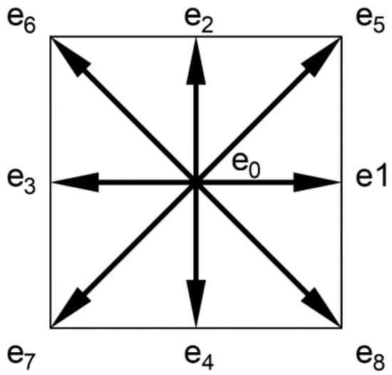
Figure 1.
D2Q9 velocity sets with nine directional discretized velocity.
In D2Q9 model standard LBM simulation, the lattice cell size is , the time step is , and the density distribution function is , which describes the total fluid molecular mass moving with specific velocity per volume. By summation, is recovered to macroscopic fluid variables, density and momentum density with Equations (2) and (3).
The time derivative of undergoes two processes. The first is streaming, in which with velocity moves to ith directional neighbor lattice cell. The second is collision. Using the second law of thermodynamics, a new set of collide towards the maximum entropy equilibrium distribution function , that is the Maxwell–Boltzmann distribution, which is discretized by second order hermit polynomials corresponding to nine velocity , in which the expression is given by Equation (4).
where .
In collision process, distribution function transfers from chaos state to equilibrium state gradually. Bhatnagar et al. [24] proposed the most popular BGK model with single relaxation time , in which move towards equilibrium distribution function linearly with time,
To obtain , distribution function is transformed to the Navier–Stokes equation by Chapman–Enskog analysis, and is given by Equation (7), is lattice dimensionless fluid viscosity, which is scaled from physical fluid viscosity. As necessary, viscosity must be non-negative for numerical stability, thereby has to satisfy .
In this paper, there are two lattice Boltzmann boundary conditions: (a) non-slip resting boundary and (b) velocity boundary. The non-slip boundary rests between the fluid lattice and solid lattice, and satisfies the bounce back rule in Equation (8). bounces back to the opposite direction on the half way when streaming to ith directional neighbor lattice cell. In Equation (8), denotes the reverse direction of while the represents post collision, and is boundary lattice cells position.
Boundary with specific velocity such as inlet and outlet (see Figure 2) lacks the streaming source. The half side are unknown, namely; , , and . Zou and He [25] reconstructed the unknown distribution function from the channel velocity using Equations (9)–(11).

Figure 2.
Distribution function of Zou–He boundary.
Other boundary condition, such as periodic boundary condition, requires that outlet lattice streams to inlet lattice directly.
Body force is a common phenomenon, such as gravity and electronic field, and in Poiseuille flow, the pressure difference is presented by body force, adding an additional term associated with body force density to the BGK model, as shown in Equation (12).
3. Discrete Element Method
In this paper, particle motion and collision are simulated using the discrete element method. Lagrangian particle’s motion follows Newton’s second law in Equations (14) and (15). Particle translation is accelerated by hydrodynamic interaction force , particles collision force , and gravity force every timestep. Particle rotational acceleration depends on torque and , derived from and .
In Equations (14) and (15), and are translational and rotational velocity, respectively; and are mass and moment of inertia, respectively; is hydrodynamic force on particle calculated by immersed moving boundary, which will be discussed in the next section. and are two particles’ center vector, and are two particles’ radius. and are two particles’ velocity. The collision surface normal and tangential vector of particle i are and , respectively. Collision force in the normal and tangential direction is and .
and are divided into linear elastic force and damping force. For , linear elastic force is related to overlap of collision particle . Damping force is related to the particle’s relative velocity . The particle i normal force is given by
where constant is normal stiffness coefficient. constant is normal damping coefficient. Tangential force is caused by the rough surface sliding between two particles. Previous time step tangential overlap is forgotten in the next time step. The relative tangential velocity is , and the tangential overlap is . The tangential stiffness coefficient is and the tangential damping coefficient is [26]. The particle i tangential force is given by Equation (17).
The tangential force is limited by the Coulomb’s friction law: , thereby the final tangential force expression is given by
where is friction coefficient.
4. Immersed Moving Boundary for LBM-DEM Coupling
Different from MMB and IB, in IMB, distribution function in the non-conforming boundary lattice is divided into two parts. The first part undergoes non-equilibrium bounce back while the second part collides like normal fluid lattice. The ratio of two parts depends on solid fraction of interface lattice. In Figure 3, cells are divided into three types, and the curve is the particle boundary interface. Rectangle symbol lattice is particle cell, sphere symbol lattice is fluid cell, and pentagon symbol lattice is interface cell. The shaded section represents the fluid part of interface cell.
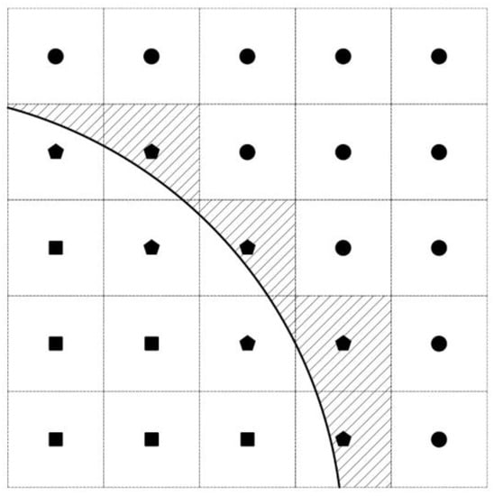
Figure 3.
Cell type of immersed moving boundary (IMB) method.
Solid fraction of interface lattice cell is , which varies from 0 to 1. This paper proposes a new calculation algorithm for single particle, which will be shown in Section 5. In multi particle collision simulation, solid fraction is calculated by summing all of the overlap area of every particle. For numerical stability, will be replaced with weight function in Equation (19), in which the two parameters have the same physical meaning. The relationship between and is shown in Figure 4, which shows that changes more slowly than when the fluid cell’s flag changes, providing a smoother transition of coupling force and a reduction of force fluctuation.
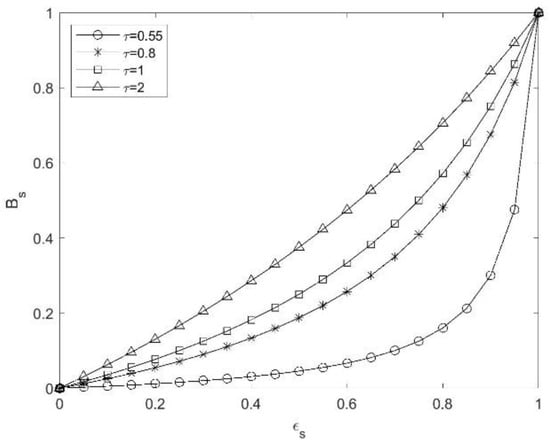
Figure 4.
Polynomial depends on .
After streaming, interface lattice obtains a new set of from its fluid neighbor lattice as the interface lattice is mixed components including fluid and solid. With the different solid fraction, the corresponding solid part distribution function will bounce back directly, which satisfies the non-equilibrium bounce back rule. If the boundary velocity is , and the boundary fluid velocity is , define and as the boundary lattice equilibrium distribution function of solid and fluid parts. The non-equilibrium part of distribution function is , which will bounce back to i direction. Considering the value change from the origin value , the non-equilibrium bounce back expression is given by Equation (20).
The fluid parts distribution function , which undergoes BGK collision, is shown in Equation (21).
Combining Equations (20) and (21), an additional term is added to collision operator, and the mix collision expression of interface lattice is given in Equation (22).
As , conventional collision operator has no effect on momentum change. New term introduces the momentum change of fluid in the interface lattice cell. The corresponding reaction force on the particle is . For numerical stability, this paper introduces conception fluid lattice indicator from MBB method [8]. If the corresponding neighbor cell is fluid, , and on the contrary, (see Figure 5). The new hydrodynamic force expression is given by Equation (24).
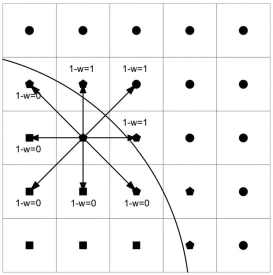
Figure 5.
Momentum exchange of modified bounce back method (MBB).
5. New Solid Fraction Calculation Algorithm
Solid fraction can be seen as the intersection area of particle geometry and LBM grid. There are three intersection states between particle and lattice, and the relationship between lattice position and particle center introduces more states for solid fraction calculation, which must be considered separately. Thus, it is difficult to calculate solid fraction cell by cell with different scheme. In the conventional method, intersection area is estimated by approximation of integral because it is difficult to calculate cell by cell.
In the new solid fraction calculation algorithm, the intersection is not calculated by the local cell intersection area, and the calculation progress is taken as a whole, wherein the intersection area depends on the other pre-calculating cells. Before calculation, the possible intersect lattice cell is marked based on the particle center and radius (see Figure 6a), and the marked cell is divided into four parts (A, B, C, D). Corresponding cell index (i, j) is given in each part, and the index origin of each part begins from the farthest cell from the particle center. i and j indicate the row and column (see Figure 6b), and the corresponding intersection area of (i, j) cell is .
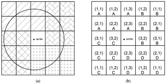
Figure 6.
Cell sets for solid fraction calculation.
is calculated individually for each of the lattice groups A, B, C, D in an ascending order of i and j (see Figure 7a), in which depends on all the pre-calculated , , . Since is difficult to calculate directly, a trick is used in which a new variable is defined, as shown in Equation (25). Equation (25) calculates the sum of all the pre-calculated , and then all the known (not include ) are subtracted from to get .
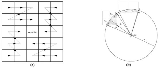
Figure 7.
Pre-interaction area calculation.
An example is shown in Figure 7b. To calculate , it is assumed that all the pre-calculated are already known, and only and are non-zero. can easily be calculated by simple geometry description, , and .
The whole progress for coding is listed as follows:
- At every time step, the particle’s new position is located, and the intersection lattice group is updated depending on the particle location. Choices of lattices for solid fraction calculation depend on the particle’s center lattice location, and the lattices’ type and index are updated every time step.
- Loop A, B, C, D into four parts.
- Loop all cells in ascending order of i and j.
- Calculate , then subtract all the known to obtain .
6. Simulation
The simulation results of three cases are given in this section. The first case is plane Poiseuille flow, a flow between plane with body force. By comparing the proposed solution and analytical solution, the accuracy of LBM in fluid simulation is verified, which is the foundation in getting an accurate hydrodynamic force on particle.
The second case is drag force on a fixed cylinder. The application of plane flow generates laminar flow with different Reynolds number, in which the corresponding analytical drag coefficient can be calculated. Thereafter, the hydrodynamic force with IMB-LBM is simulated. The simulation and analytical drag coefficient value are compared to illustrate the hydrodynamic force accuracy on static sphere.
The third case is the simulation of settlement of a single particle under the influence of gravity, in which the drag force and the velocity increase as the particle sinks. In this case, the final velocity reaches equilibrium when the drag force is equal to the gravity force.
The fourth case is the simulation of two particles falling freely in a container, releasing two particles in the center line with body force to be able to verify the particle motion: “drafting, kissing, and tumbling” phenomenon.
6.1. Poiseuille Flow
Before real particle flow of IMB-DEM-LBM simulation, LBM is applied to Poiseuille flow. The top and bottom boundary are fixed boundary, and the left and right boundary are periodic boundary. Pressure at inlet and outlet accelerate incompressible fluid flow through two plain plates (see Figure 8).
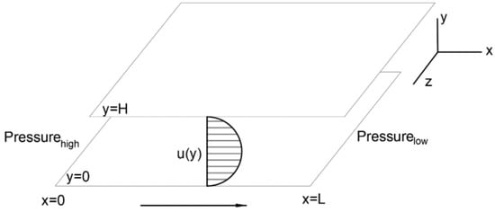
Figure 8.
Poiseuille flow.
The distance between two plates is H, and fluid viscosity is . Pressure drop is replaced with body force in Equation (26).
The corresponding velocity profile analytical solution resolved from Navier–Stokes equation with boundary condition is given by Equation (27).
The simulation domain cell number is , and the dimensionless variables are listed as follows: (a) collision time , (b) dimensionless viscosity , (c) max dimensionless velocity in x direction is 0.1, (d) velocity in y direction is 0, (e) cell size , and (f) timestep . Steady simulation result is obtained at 300 time steps. The velocity profile at using the coarse grid solution and analytical solution is shown in Figure 9. Based on the result, the standard error estimate , is . By comparing the simulation result and analytical result, the accuracy of LBM fluid simulation is verified, which is the foundation in obtaining a more accurate hydrodynamic force on particle.
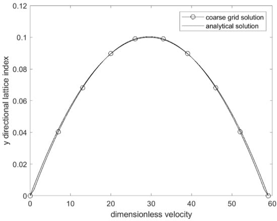
Figure 9.
Comparison of analytical solution and proposed solution at x = 30.
6.2. Drag Force on Fix Cylinder
The accuracy of hydrodynamic force on particle is critical for IMB-DEM-LBM particle flow simulation. A fixed cylinder is located in a channel with fixed boundary velocity (see Figure 10). Different inlet velocity generates steady laminar flow with different Reynolds number. The cylinder drag coefficient is expressed analytically by a function of Reynolds number, which is shown in Equation (28) [27,28].

Figure 10.
Distribution velocity of D2Q9.
The inlet velocity is simulated with Zou–He boundary condition. The drag force on cylinder is , and the fluid velocity at cylinder is . The drag coefficient is shown in Equation (29).
The simulation domain cell number is . The dimensionless variable are listed as follows: (a) collision time , (b) dimensionless viscosity , (c) cell size , and (d) timestep . The boundary inlet velocity are 0.01, 0.03, 0.05, 0.1, 0.15, 0.2, and the corresponding Reynolds number are 9, 22.5, 45, 90, 135, 180, respectively. The steady simulation result of velocity vector with inlet velocity 0.2 is shown in Figure 11. The simulation force on cylinder is obtained, and then drag coefficient is calculated, as well as the , as shown in Table 1. A comparison between the analytical solution and the proposed solution is shown in Figure 12. As shown, the simulation result agrees with the analytical result. In addition, the simulation has a better performance at high Reynolds number. The simulation error at low Reynolds number is caused by velocity fluctuation near cylinder boundary.
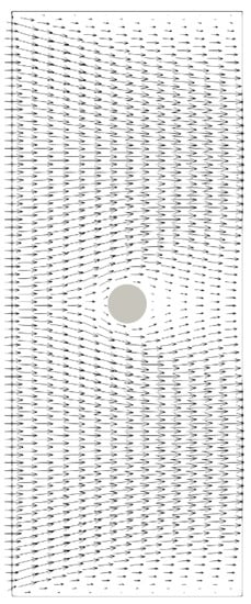
Figure 11.
Velocity vector with Uinlet = 0.2 and Re = 180.

Table 1.
Simulation and analytical drag coefficient of different Reynolds number.
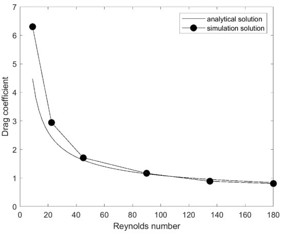
Figure 12.
Drag coefficient with different Reynolds number.
Error at low Reynolds number is introduced by numerical noise. In low Reynolds number flow, the interaction drag force is not dominant but it helps match the particle and fluid velocity. The particle velocity oscillation is inevitable in the simulation, which is different from the actual physical progress. Using a large drag force helps in decreasing oscillation. This shows the limitation of the coupling method presented in this study; however, this error can be neglected because low Reynolds number condition is rare for particle flow in coastal engineering.
6.3. Single Particle Settlement
To demonstrate the feasibility of IMB-DEM-LBM for particle movement, a particle that falls in a container filled with liquid under the effect of gravity is simulated to illustrate velocity accuracy of a moving particle.
The square container’s physical size , and the domain boundary is no slip bounce back boundary. The gravity acceleration is , particle radius is , particle density is , fluid density is , dynamic fluid viscosity is , conversion factor , , the lattice domain size is , and particle radius is 5. The initial particle state is stationary and the fluid velocity is zero. The particle position and velocity profile during settlement is shown in Figure 13.
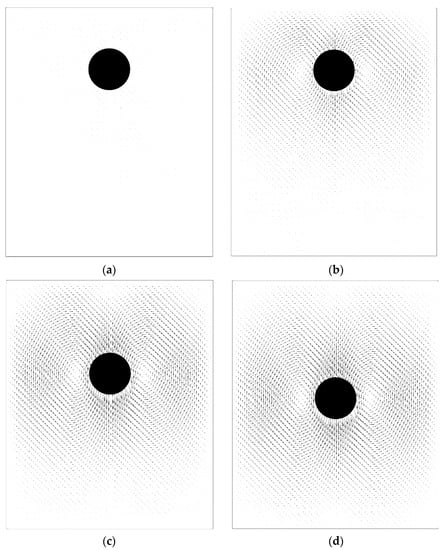
Figure 13.
Sinking particle’s location and change in velocity with time wherein two eddies appear at the symmetry sides as the particle moves: (a) time step = 0; (b) time step = 20; (c) time step = 300; (d) time step = 500.
The drag force on particle increases as the sinking velocity increases, and the particle velocity reaches equilibrium when the drag force is equal to the gravity force. The analytical equilibrium sinking velocity is given by Equation (30) [29]. Therefore, the analytical sinking equilibrium velocity is . The simulation result using the method proposed in this study is shown in Figure 14, which indicates an equilibrium velocity of about 5.75 × 10⁻³ m/s.
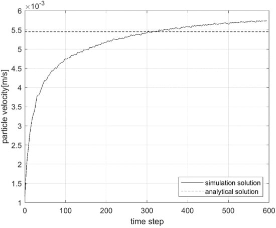
Figure 14.
Single particle settlement velocity with time step.
6.4. Particles Settlement and Collision
To demonstrate the feasibility of IMB-DEM-LBM for particle collision in liquid, the settlement of two particles in the same path is simulated. When two departed particles are realized in the container center line, the particles’ initial velocity is zero and both of them start to move due to gravity. The upper particle is in the wake of the lower particle, and is accelerated to catch up with the lower particle [30]. They will then kiss together and settle together as a whole. Little fluctuation in the flow may make them depart from each other. The total progress is called “drafting, kissing, and tumbling” or DKT, in which simulation of this phenomenon can be done by different techniques such as FEM [31,32], IB-LBM [12]. “Drafting, kissing and tumbling” is a random phenomenon, which occurs in the settlement and collision of particles. In experiments, the time interval of the kissing progress depends on when the random disturbance happens. Unfortunately, the experiment cannot catch how and when the disturbance occurs. Hence, the purpose of the simulation is only to show that these phenomena can be replicated or depicted by the method presented in this study.
For saving computational power, the two particles’ physical initial velocity is . The initial velocity allows particles to reach balance velocity with less time. Physical domain is mm, gravity is , particle radius is , fluid density is , and particles mass is . The distance of two particles’ center is . The collision time is , and the lattice domain size is . The particles’ position and velocity profile is shown in Figure 15a–h for the corresponding time steps at t = 0, 40, 80, 130, 190, 230, 260, 300.
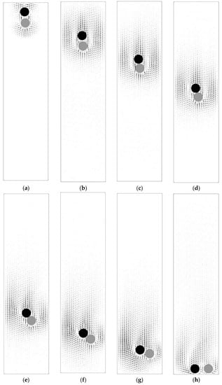
Figure 15.
Two particles settling, drafting, kissing, and tumbling.
In Figure 15a, the two particles begin to settle together, and the particles get closer and closer in Figure 15b,c. In Figure 15d, the two particles kiss each other, and begin to drift together. In Figure 15d,e, the two particles adhere together. In Figure 15f,h, little fluctuation makes the particles depart from each other. The particles’ motion in Figure 14 satisfies “drafting, kissing, and tumbling” phenomenon, which occurred in the experiment conducted by Fortes [33].
Figure 16 shows the x and y velocity of the two settling particles. In Figure 16b, the whole progress can be divided into three time periods. At timestep 0–75, the upper particle chases the lower one, and at timestep 75–190, the two particles drift together and collide repeatedly. At timestep 190–300, the two particles depart from each other. In drift progress, gravity potential is converted into x momentum, as shown in Figure 16a, and when two particles depart from each other, the x coordinate momentum is exchanged to the fluid around the particles, so all the particles’ x velocity decreases, as shown in Figure 16a.
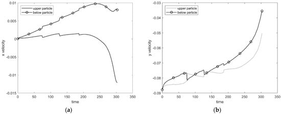
Figure 16.
Velocity of two settlement particles.
7. Conclusions
This paper presents a promising procedure of IMB-DEM-LBM for particle flow simulation of rigid particles such as soil particles, in which IMB and IB are combined to get the new hydrodynamic force calculation expression. To improve the accuracy of solid fraction calculation, a new method, which can easily be understood and is easy to program, was proposed based on the basic geometric relationship for solid fraction calculation. Three cases were simulated, which includes theoretical comparison and experiment phenomenon verification. The first case was Poiseuille flow, which is a routine test for hydrodynamic simulation. The second case is drag coefficient simulation, which was performed to test the accuracy of hydrodynamic force on particle. By comparing the analytical solution and proposed solution, the new hydrodynamic force expression is verified, which makes the new solid fraction calculation algorithm suitable, feasible, and accurate for IMB. The third case is particles collision, which was performed to extensively test the movement of particles. The simulation results coincide with an experiment conducted in the literature, verifying the new method for more complex boundary conditions, as well as providing steady numerical solution for quick flag change problem. Based on a rigorous theoretical derivation and example verification, the new method presents an outstanding performance on particle-flow simulation. The simulation conducted in this paper is two-dimensional; however, IMB, DEM, and LBM can be easily extended to three dimensions (see Appendix A). The new solid fraction method can be extended to three-dimensional problems by replacing the two-dimensional lattice index with three-dimensional lattice index, in which the other conception is the same as the two-dimensional case.
Author Contributions
Conceptualization, R.Z.; methodology, R.Z.; formal analysis, R.Z.; writing—original draft preparation, R.Z.; writing—review and editing, P.R.D.; supervision, H.-J.K. All authors have read and agreed to the published version of the manuscript.
Funding
The APC was funded by the National Research Foundation of Korea, grant number NRF-2020R1I1A3A04036506, and the Korea Institute of Energy Technology Evaluation and Planning (KETEP), grant number 20183010025200.
Institutional Review Board Statement
Not applicable.
Informed Consent Statement
Not applicable.
Data Availability Statement
The data presented in this study are available on request from the corresponding author.
Acknowledgments
This work was supported by the National Research Foundation of Korea, grant number NRF-2020R1I1A3A04036506, and the Korea Institute of Energy Technology Evaluation and Planning (KETEP), grant number 20183010025200.
Conflicts of Interest
All the authors have read and approved this version of the article, and due care has been taken to ensure the integrity of the work. All the authors have no conflicts of interest to declare.
Appendix A
This algorithm can be extended to 3D sphere. The selected lattice is divided into eight parts, and the lattice index extends to i, j, k. The corresponding solid fraction is the overlap volume of lattice cell and particle sphere. Other variables and steps follow the 2D case. In Figure A1, is volume OABCD minus three tetrahedron volume. Vector , , are used to calculate the intersect area CBD. Thereafter, volume OABCD can be obtained, and the tetrahedron volume is calculated by three vectors.
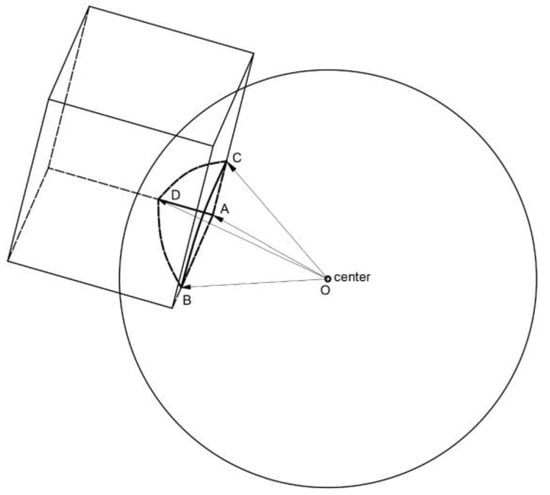
Figure A1.
3D solid fraction calculation.
References
- Neuhauser, M. Development of a Coupled SPH-ALE/Finite Volume Method for the Simulation of Transient Flows in Hydraulic Machines; Ecole Centrale de Lyon: Écully, France, 2014. [Google Scholar]
- Chopard, B.; Ansumali, S.; Patil, D.V.; Karlin, I.; Venkatesan, D.S. Fluid dynamics, soft matter and complex systems: Recent results and new methods. Philos. Trans. R. Soc. A 2020, 378, 20190395. [Google Scholar] [CrossRef] [PubMed]
- Ziegler, D.P. Boundary conditions for lattice Boltzmann simulations. J. Stat. Phys. 1993, 71, 1171–1177. [Google Scholar] [CrossRef]
- Filippova, O.; Hänel, D. Lattice-Boltzmann simulation of gas-particle flow in filters. Comput. Fluids. 1997, 26, 697–712. [Google Scholar] [CrossRef]
- Ladd, A.J.C. Numerical simulations of particulate suspensions via a discretized Boltzmann equation. Part 1. Theoretical foundation. J. Fluid Mech. 1994, 271, 285–309. [Google Scholar] [CrossRef]
- Huang, W.-X.; Tian, F.-B. Recent trends and progress in the immersed boundary method. Proc. Inst. Mech. Eng. Part C J. Mech. Eng. Sci. 2019, 233, 7617–7636. [Google Scholar] [CrossRef]
- Bouzidi, M.; Firdaouss, M.; Lallemand, P. Momentum transfer of a Boltzmann-lattice fluid with boundaries. Phys. Fluids. 2001, 13, 3452–3459. [Google Scholar] [CrossRef]
- Yu, D.; Mei, R.; Luo, L.-S.; Shyy, W. Viscous flow computations with the method of lattice Boltzmann equation. Prog. Aerosp. Sci. 2003, 39, 329–367. [Google Scholar] [CrossRef]
- Soundararajan, K.K. Multi-Scale Multiphase Modelling of Granular Flows. Ph.D. Thesis, University of Cambridge, Cambridge, UK, March 2015. [Google Scholar] [CrossRef]
- Bonaccorso, F.; Succi, S.; Lauricella, M.; Montessori, A.; Tiribocchi, A.; Luo, K.H. Shear dynamics of confined bijels. AIP Adv. 2020, 10, 095304. [Google Scholar] [CrossRef]
- Peskin, C.S. Flow patterns around heart valves: A numerical method. J. Comput. Phys. 1972, 10, 252–271. [Google Scholar] [CrossRef]
- Feng, Z.G.; Michaelides, E.E. The immersed boundary-lattice Boltzmann method for solving fluid–particles interaction problems. J. Comput. Phys. 2004, 195, 602–628. [Google Scholar] [CrossRef]
- Ota, K.; Suzuki, K.; Inamuro, T. Lift generation by a two-dimensional symmetric flapping wing: Immersed boundary-lattice Boltzmann simulations. Fluid Dyn. Res. 2012, 44, 045504. [Google Scholar] [CrossRef]
- Hassanzadeh, A.; Pourmahmoud, N.; Dadvand, A. Numerical simulation of motion and deformation of healthy and sick red blood cell through a constricted vessel using hybrid lattice Boltzmann-immersed boundary method. Comput. Methods Biomech. Biomed. Engin. 2017, 20, 737–749. [Google Scholar] [CrossRef]
- Tiribocchi, A.; Bonaccorso, F.; Lauricella, M.; Melchionna, S.; Montessori, A.; Succi, S. Curvature dynamics and long-range effects on fluid–fluid interfaces with colloids. Soft Matter. 2019, 15, 2848–2862. [Google Scholar] [CrossRef]
- Jie, W. Development of a Novel Immersed Boundary-Lattice Boltzmann Method and Its Applications. Ph.D. Thesis, National University of Singapore, Singapore, May 2010. [Google Scholar]
- Liu, W.; Wu, C.-Y. A hybrid LBM-DEM numerical approach with an improved immersed moving boundary method for complex particle-liquid flows involving adhesive particles. arXiv 2019, arXiv:1901.09745. [Google Scholar]
- Noble, D.; Torczynski, J. A lattice-Boltzmann method for partially saturated computational cells. Int. J. Mod. Phys. C 1998, 9, 1189–1201. [Google Scholar] [CrossRef]
- Cook, B.K.; Noble, D.R.; Williams, J. A direct simulation method for particle-fluid systems. Eng. Comput. 2003, 21, 151–168. [Google Scholar] [CrossRef]
- Owen, D.R.J.; Leonardi, C.R.; Feng, Y.T. An efficient framework for fluid–structure interaction using the lattice Boltzmann method and immersed moving boundaries. Int. J. Numer. Methods Eng. 2011, 87, 66–95. [Google Scholar] [CrossRef]
- Galindo-Torres, S.A. A coupled Discrete Element Lattice Boltzmann Method for the simulation of fluid–solid interaction with particles of general shapes. Comput. Methods Appl. Mech. Eng. 2013, 265, 107–119. [Google Scholar] [CrossRef]
- Barber, C.B.; Dobkin, D.P.; Huhdanpaa, H. The quick hull algorithm for convex hulls. ACM Trans. Math. Softw. 1996, 22, 469–483. [Google Scholar] [CrossRef]
- Jones, B.D.; Williams, J.R. Fast computation of accurate sphere-cube intersection volume. Eng. Comput. 2017, 34, 1204–1216. [Google Scholar] [CrossRef]
- Bhatnagar, P.L.; Gross, E.P.; Krook, M. A Model for Collision Processes in Gases. I. Small Amplitude Processes in Charged and Neutral One-Component Systems. Phys. Rev. 1954, 94, 511–525. [Google Scholar] [CrossRef]
- Zou, Q.; He, X. On pressure and velocity boundary conditions for the lattice Boltzmann BGK model. Phys. Fluids 1997, 9. [Google Scholar] [CrossRef]
- Hoomans, B.P.B. Granular Dynamics of Gas-Solid Two-Phase Flows. Ph.D. Thesis, Universiteit Twente, Enschede Dutch, The Netherlands, January 2020. [Google Scholar]
- Schiller, L.; Naumann, A. A drag coefficient correlation. Z. Ver. Dtsch. Ing. 1935, 77, 318–320. [Google Scholar]
- Ellendt, N.; Lumanglas, A.M.; Moqadam, S.I.; Mädler, L. A model for the drag and heat transfer of spheres in the laminar regime at high temperature differences. Int. J. Therm. Sci. 2018, 133, 98–105. [Google Scholar] [CrossRef]
- Iglberger, K.; Thürey, N.; Rüde, U. Simulation of moving particles in 3D with the Lattice Boltzmann method. Comput. Math. Appl. 2008, 55, 1461–1468. [Google Scholar] [CrossRef]
- Mirzaii, I.; Passandideh-Fard, M. Modeling free surface flows in presence of an arbitrary moving object. Int. J. Multiph. Flow. 2012, 39, 216–226. [Google Scholar] [CrossRef]
- Patankar, N. A formulation for fast computations of rigid particulate flows. Cent. Turbul. Res. Annu. Res. Briefs 2001, 2001, 185–196. [Google Scholar]
- Glowinski, R.; Pan, T.W.; Hesla, T.I.; Joseph, D.D. A distributed Lagrange multiplier/fictitious domain method for particulate flows. Int. J. Multiph. Flow 1999, 25, 755–794. [Google Scholar] [CrossRef]
- Fortes, A.F.; Joseph, D.D.; Lundgren, T.S. Nonlinear mechanics of fluidization of beds of spherical particles. J. Fluid Mech. 1987, 177, 467–483. [Google Scholar] [CrossRef]
Publisher’s Note: MDPI stays neutral with regard to jurisdictional claims in published maps and institutional affiliations. |
© 2021 by the authors. Licensee MDPI, Basel, Switzerland. This article is an open access article distributed under the terms and conditions of the Creative Commons Attribution (CC BY) license (https://creativecommons.org/licenses/by/4.0/).