Abstract
In this study, we proposed a novel machine-learning-based functional electrical stimulation (FES) control algorithm to enhance gait rehabilitation in post-stroke hemiplegic patients. The electrical stimulation of the muscles on the paretic side was controlled via deep neural networks, which were trained using muscle activity data from healthy people during gait. The performance of the developed system in comparison with that of a conventional FES control method was tested with healthy human subjects.
1. Introduction
A stroke occurs when the blood supply to the brain is blocked by an ischemic or hemorrhagic event due to a thrombus inside the blood vessel [1]. Strokes are commonly accompanied by several functional disorders such as muscle paralysis, speech–language disorders, memory problems, and emotional problems depending on the degree of brain damage [2]. Approximately 50% of stroke patients suffer from hemiplegia, a major cause of immobility, which degrades patients’ quality of life. In the entire rehabilitation process, restoration of mobility is the first priority. Among the various types of mobility impairments, foot drop caused by spasticity of the ankle joint is the most common in hemiplegic patients [3,4].
To alleviate spasticity and improve functionality in post-stroke patients, many studies have been conducted on physical and neurological treatments, such as exercise therapy and electric stimulation therapy [5,6,7]. Among these treatments, functional electrical stimulation (FES) is one of the most widely used methods for the rehabilitation of post-stroke hemiplegic patients. Using FES, muscles can be directly contracted to elicit joint movement by evoking a series of low-energy electrical impulses (action potentials) to excite nerves or muscles. In addition, FES has an advantage over other physical rehabilitation methods in terms of treating neurological injuries, including neural plasticity [8,9,10].
Many studies have proven that gait ability can be improved by using FES for isometric contraction therapy and walking therapy for the paretic limb [8,11]. Liberson et al. demonstrated an improvement in dorsiflexion in post-stroke patients after FES-based treatment [12]. Chae et al. demonstrated that FES-aided walking influences afferent inputs to the central nervous system, which can improve brain plasticity [12,13].
In the application of FES to gait assistance, the amplitude and timing of the FES signal needs to be adequately controlled. Through tuning of the amplitude and timing, the optimal envelope of the FES signal can be acquired to generate walking motion. Early studies employed a rectangular pattern of the FES signal with on/off switching only [12]. Subsequent studies introduced the trapezoidal envelope with ramp up/down for the FES signal to relieve muscle fatigue that can be caused by abrupt changes in the electric stimulus in the rectangular pattern [14].
It was argued that neither the rectangular on/off pattern nor the trapezoidal pattern of the FES envelope was close to the electromyogram (EMG) patterns observed during natural walking [15,16,17]. Researchers have attempted to enhance the rehabilitation outcome by designing the envelope of the FES signal to match the EMG patterns acquired from natural movements. Lyons et al. demonstrated that the dorsiflexion angle increased by 76%, and the overall current decreased by 47% when an electrical stimulation pattern close to the natural EMG envelope was employed [15]. These studies employed a rather simple approach by mapping the EMG envelope to the intensity of the FES. However, this approach had limitations in terms of the generation of accurate muscle forces required for producing natural gait motion.
To generate a natural movement, the relationship among FES, EMG, and the required joint torque and motion should be identified. Frigo et al. estimated the joint torque based on the measurement of evoked EMG, which was a combined signal of volitional EMG and FES artifacts measured using surface electrodes [18]. The drawback of this method was that the estimation was highly sensitive to the measurement of EMG, where the measurement was easily affected by external disturbances and electrode attachment conditions. Koji et al. investigated the relationship between the joint torque and FES intensity through isometric contraction tests. Their experimental results yielded a linear model for the joint torque and FES amplitude [19]. This linear model was used to simply estimate the FES intensity, which was required to produce the target joint torque. However, the model was inappropriate for the estimation of joint torque during dynamic body movements owing to the complexity of the neuromusculoskeletal system of the human body [20]. Other researchers employed Hill’s muscle model consisting of a mechanical spring and a damper to estimate joint torque based on EMG data [21,22]. While this approach was robust in the application of muscle stimulation, it suffered from variability in EMG measurement caused by electrode reposition, skin condition, and muscle fatigue [23].
In recent years, machine learning has been actively used in various applications. Machine learning algorithms can learn from training data to make estimations, predictions, or decisions by themselves. Among the many developed machine learning techniques, deep neural networks (DNNs) have shown outstanding performance in handling nonlinearity and noisy signals. As an alternative to mathematical models for the human musculoskeletal system, such as Hill’s muscle model, the DNN model can be used to estimate the joint torque to produce a desired motion. Recent studies have shown that a DNN model is capable of estimating the joint torque in the presence of high noise in biosignals [24,25,26,27]. Li et al. demonstrated that estimation accuracy can be improved by using biosignal data from agonist and antagonist muscles, rather than from agonists alone [28]. Among many DNN models, the convolutional neural network (CNN) appears to be a promising model for many applications such as estimation models for biosignals, medical image segmentation, and medical diagnosis [29,30,31,32]. Specifically, it performs well in extracting features from time-series data, such as EMG [32].
To predict the required joint torques for the motion of the paretic limb using a neural network model, a natural choice for the input to the network would be EMG signals from the unaffected limb [33,34,35]. Bong et al. developed a robotic rehabilitation system with a muscle-to-muscle interface for post-stroke hemiplegic patients [35]. In the rehabilitation system, the FES intensity on the target muscles at the paretic side was controlled by an online comparison of the EMG signals from the paretic and unaffected sides.
Therefore, we proposed a machine learning technique to control gait rehabilitation systems for hemiplegic patients. The FES input to the paretic side is generated based on EMG data collected from normal, natural gaits to provide a reference walking pattern for the paretic side. The envelopes of the EMG signals were functionalized for various walking speeds. Using the functionalized EMG data as the input, the neural network model predicted the desired joint torque, and the amplitude of the FES input to the paretic leg was determined using the linear relationship between the FES and joint torque. The effectiveness of the proposed technique was tested in healthy human subjects through isometric contraction and treadmill walking experiments. Its performance was compared with that of a trapezoidal envelope of FES intensity, which was conventionally used in clinical trials. The experimental results showed that leg motion could be improved by relieving muscle fatigue and increasing the range of joint motion with the proposed control system.
The remainder of this paper is organized as follows: Section 2 describes the proposed FES control algorithm. Section 3 explains the experiments conducted to test the FES control system. Section 4 and Section 5 summarize and discuss the experimental results, respectively. Section 6 concludes and proposes future works.
2. Methods
Figure 1 illustrates a schematic of the gait rehabilitation system for post-stroke hemiplegic patients. As the patient is incapable of generating sufficient muscle force and range of motion in the paretic side, the muscle activities induced by FES are designed to assist the patient to generate a natural gait motion with sufficient muscle force and range of motion.
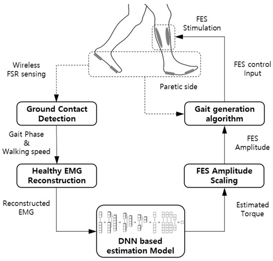
Figure 1.
Schematic of the FES control algorithm.
In the proposed rehabilitation system, the ground reaction forces on the unaffected and paretic sides were measured using force-sensitive resistors (FSR) to determine the gait phase and walking speed on the paretic side. With the gait phase and walking speed, the reference EMG envelopes for the muscles on the paretic side were determined. As it is difficult even for the patient’s unaffected side to perform the muscle activities yielding normal, natural gait patterns, the reference EMG data were acquired from healthy subjects. Subsequently, the envelopes of the EMG signals were functionalized for various walking speeds. With the functionalized EMG envelope as the input, a DNN model predicted the joint torque for a specific gait phase, which enabled natural ankle movement of the paretic side. Using the linear model between the joint torque and FES intensity, the amplitude of the FES was determined based on the joint torque estimated by the DNN model. The FES signal applied to the muscles on the paretic side was controlled based on the foot–ground contact information.
2.1. Measurement and Processing of EMG Data
To provide a reference EMG for the paretic side, EMG data were collected from six healthy male subjects aged between 20 and 30 years. The EMG data were collected during treadmill walking through off-the-shelf wireless surface EMG electrodes (Delsys Inc., USA). The EMG was measured from the soleus and tibialis anterior (TA) with walking speeds ranging from 1 to 5 km/h. Since the soleus and TA are the prime movers of ankle motion (plantarflexion and dorsiflexion), the EMG patterns of the two muscles can be used to describe the muscle activities for ankle motion during gait.
The acquired EMG data were rectified using a 6th order high-pass filter (HPF) with a cutoff frequency of 40 Hz. Subsequently, the rectified EMG signals were divided into gait cycles with 1000 data points so that the signals could be ensemble-averaged over gait cycles. To determine the gait cycle and gait phase, wireless FSRs were attached to the soles of two feet to gather ON/OFF information at the heels and toes based on a predetermined threshold. Measurements from immovable contact points during gaits, such as the toes and the first metatarsal heads, were used to provide stable contact information.
The EMG signal was then normalized with respect to the peak value of the rectified EMG at a walking speed of 5 km/h. Figure 2 shows the ensemble average of rectified EMG from the soleus and tibialis anterior with varying walking speeds on the treadmill.
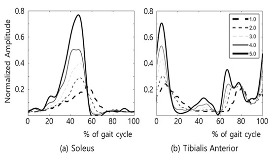
Figure 2.
EMG of (a) soleus and (b) TA during treadmill gait at various walking speeds (km/h).
The EMG magnitude of the upper 15% was considered as muscle activation, and the muscle activation during gait could be characterized as follows [36]:
- (a)
- The activation timing of the soleus after the heel strike was unchanged regardless of the changes in walking speed.
- (b)
- The activation of soleus ends at about the timing of toe off.
- (c)
- The co-contraction of Soleus and TA occurs only for a short time at low walking speeds (1–2 km/h).
- (d)
- The activation timings of the soleus and TA nearly coincide with the timings of heel and toe contacts in higher walking speeds (3–5 km/h).
Based on the muscle activation model, the EMG envelopes were functionalized using trigonometric functions by using a curve fitting tool in MATLAB software (MathWorks, Natick, MA, USA). Functionalized EMG envelopes are shown in Figure 3. The minimum and maximum amplitudes of the functionalized EMG envelopes were chosen as feature points. Figure 3a,b show the feature points in the percentile gait cycle, where the soleus and TA had three and five feature points, respectively: S_1, S_2, and S_3 for the soleus and T_1, T_2, T_3, T_4, and T_5 for the TA. Figure 3c,d show the changes in the functionalized EMG envelopes depending on the changes in the walking speed. The observations from the gait experiments showed that the positions of all the feature points in the percentile gait cycle varied depending on the walking speed, except for T_3, as shown in Figure 3d.
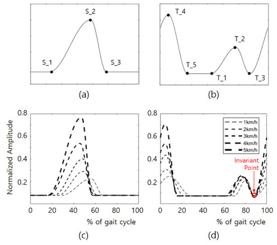
Figure 3.
Feature points and functionalized envelop of soleus and TA in the percentile gait cycle; (a) feature points of soleus, (b) feature points of TA, (c) envelope function of soleus, (d) envelope function of TA.
2.2. Control of the FES Based on Reference EMG
To apply an FES capable of producing the desired EMG patterns, understanding the relationship between the reference EMG and its corresponding FES is essential. Few studies have addressed this issue; however, Koji et al. used a simple linear model mapping from EMG to FES [19]. The problems in controlling FES can be alleviated by subdividing the FES control into two stages: mapping from the reference EMG to the FES envelope and generating the FES signal depending on the gait phase.
In this study, the FES envelope was computed using a DNN model based on the reference EMG described in the previous section. The FES signals were applied to the target muscles according to the gait phase detected by the FSR sensors.
2.2.1. Mapping from EMG to FES
Mathematical models of the musculoskeletal system have been commonly employed to estimate the joint torque from the reference EMG [37]. However, through this model-based approach, computing the muscle activities of musculoskeletal models from EMG signals is difficult [22].
Recently, machine learning techniques have been employed as an alternative to model-based approaches for joint torque estimation. Machine learning is an algorithm type that enables a computer to learn by itself without any specific guidelines for training conditions, and this approach has shown prowess in identifying an underlying pattern hidden inside a highly noisy dataset [26]. Among a variety of machine learning techniques, deep learning has become popular owing to its effectiveness in handling nonlinear problems with anti-noise robustness. DNNs are a type of artificial neural network (ANN) model based on multi-layer perceptron (MLP) and deep learning training. As a type of DNN model, a CNN, featuring convolution and pooling layers, has the strength in the extraction of key features of input data. While CNN is commonly used for two-dimensional input data such as images, one-dimensional CNNs (1D CNNs) are also effective in analyzing time-series data, such as EMG signals.
To estimate the required joint torque from the reference EMG, a combination of a 1D CNN and a fully connected MLP were employed in this study. The structure of CNN–MLP model is illustrated in Figure 4. In the network model, there were three 1D CNN layers in the series. Each 1D CNN had a convolution and pooling layer. The three convolution layers had a kernel size of 16 and a filter size of 128, and the three pooling layers had pooling sizes of 6, 4, and 2. The three 1D CNNs compute the convolution with stride lengths of 1, 0, and 1. After the 1D CNNs, the flattened layer was located to match the dimensions of the dataset. Following the flattening layer, five fully connected MLPs with layer sizes of 129, 128, 128, 64, and 1 were used in the series. For the activation functions of MLPs, the first four MLPs used rectified linear unit (ReLU), whereas the last MLP used a hyperbolic tangent function (Tanh) to take nonlinearity into account. For model training, the Adam optimizer was employed, which was stable and effective in training a DNN.
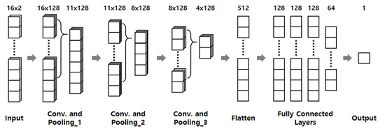
Figure 4.
Structure of neural network model for estimation of joint torque.
To train the CNN–MLP model, the training data were acquired from isometric contraction tests using a customized apparatus described in Section 3.2.2, where the EMG at the soleus and TA and the corresponding ankle torque were measured. The dataset was divided into training, evaluation, and test sets with a ratio of 6:2:2. To avoid overfitting of the model, the training ended after it reached the fifth epoch of the dataset. The final root means square error (RMSE) value evaluated using the test dataset was 4.966.
The developed CNN–MLP model was employed to estimate the ankle joint torque from the reference EMG envelopes for the soleus and TA. Figure 5a–c show the foot-ground contact information at the heel and toe on the paretic side, the reference EMG envelopes for the soleus and TA, and the estimated ankle joint torque, respectively.
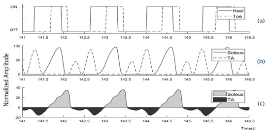
Figure 5.
Datasets from the estimation progress of CNN–MLP model at 1 km/h. (a) foot-ground contact information on paretic side, (b) reference EMG envelope of the soleus and TA, (c) estimated joint torque.
Using the modulated EMG profiles as input, the CNN–MLP model estimated the joint torque at the ankle on the paretic side. As can be observed from the EMG data in Figure 2, the co-activation of the soleus and TA is rarely observed during gait, with the exception of the gait in the low-speed range (below 2 km/h). Under this assumption, the positive torque in Figure 5c indicates the plantar flexion solely by activation of the soleus, and the negative torque indicates dorsiflexion solely by the activation of the TA.
The developed CNN–MLP model computes the joint torque to produce the desired motion on the paretic side. As for the FES signals to be applied to the target muscle on the paretic side, amplitude of the FES was modeled to be proportional to the joint torque, as in the study of [19]. As the soleus and TA were modeled to activate without co-contraction during cyclic gait motion, amplitudes of the FES to the soleus and the TA were proportional to the positive and negative joint torques, respectively.
2.2.2. Generation of FES Signal According to Gait Phase
To generate cyclic gait motion, it is essential to apply the FES signals to the target muscles at a correct time, considering the walking speed. The walking speed can be represented by the time difference of heel strikes (TDH), which is the difference between the times of heel-ground contact of the two feet, measured by FSR sensors. Based on the estimated TDH, the profiles of the reference EMG envelopes were determined and fed to the soleus and TA.
Along with the measurement from FSR sensors, the finite state machine (FSM) is commonly used to determine the state in the gait cycle [38,39]. In this study, a threshold-based FSM with FSR sensors was used to determine the gait phase because it is highly accurate for both indoor and outdoor environments with a low computational demand [40].
Figure 6 illustrates that the FSM-based control algorithm modulates the amplitude and duration of the FES for the soleus and TA. In one gait cycle, there are three states, and the gait state is determined by the on/off signals from the four FSR sensors on the two feet. Depending on the gait state, different control laws were applied to produce FES signals to the soleus and TA.
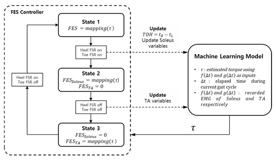
Figure 6.
FSM control algorithm of the gait rehabilitation system. (: heel contact time of left foot, : heel contact time of right foot, TDH: time difference of heel contact, : elapsed time of the system, : envelope function of the soleus, : envelope function of the TA).
State 1 starts at the heel strike on the paretic side. As state 1 starts, a new gait cycle is initiated, and the TDH is updated. In state 1, the reference EMG for the soleus was updated based on the newly updated TDH, while that of the TA was identical to the previous gait cycle. The reference EMG data were fed into the DNN model to yield the joint torque. Subsequently, the FES signals proportional to the positive and negative joint torques were applied to the soleus and TA, respectively.
State 2 starts at the toe strike on the paretic side. The reference EMG for the TA is updated based on the current TDH, whereas the FES signal for the TA was set to zero. In state 2, the FES signal was applied to the soleus only, based on the reference EMG for the soleus.
State 3 is the swing phase and starts at toe-off on the paretic side. In state 3, the FES for the soleus was set to zero, and the FES signal was applied to the TA only, based on the reference EMG for the TA.
When the FSR sensors detect the loss of foot-ground contact for both feet, the control algorithm enters the emergency stop state and sets the FES for the soleus and TA to zero.
3. Experiments
While the developed system was designed for the rehabilitation of hemiplegic patients, healthy human subjects were used for testing as a preliminary evaluation of the system. The developed DNN-based FES envelope prediction system was compared with a conventional system using a trapezoidal FES envelope, which is widely used in commercial FES devices. Performance of the two systems (DNN-based envelope (DBE) and TE (trapezoidal envelope)) was compared considering the following factors: (1) the range of motion of the ankle joint during treadmill gait at various walking speeds, and (2) muscle fatigue after the repetitive isometric contraction of the ankle joint.
In this study, 11 healthy male subjects aged between 20 and 30 years participated in the experimental tests. From six subjects, EMG data during treadmill gait were collected, and the data were used to train the DNN model, as described in Section 2.2. Five subjects participated in the comparison tests of the DBE and TE. Each subject was fully informed about the features of the developed system and procedures of the experiments before signing a consent form. The experiments involving human subjects were approved by the Institutional Review Board of Korea University in Seoul, Korea (KUIRB–2019–0061–01).
3.1. FES Control System
A dual-channel FES unit (Roscoe Medical, USA) was used to stimulate the soleus and TA (Figure 7a). A microcontroller unit (Arduino, Italy) was used to control the FES device using Bluetooth wireless communication. The FES signal with a frequency of 40 Hz and pulse width of 200 µs was applied to human subjects. The maximum amplitudes of the FES were determined by the pain threshold of each subject.
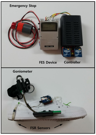
Figure 7.
FES device (above) and experimental shoes (below).
Modularized wireless EMG sensors (Delsys Inc., Boston, MA, USA) were used to measure muscle activity in the soleus and TA of the subjects. The bipolar surface electrodes were positioned on the skin surface of the bellies of the muscles along with the muscle fiber directions. The skin surface, where the electrodes were placed, was shaved and scrubbed. The EMG sensors were then fastened using elastic bandages to avoid noises caused by electrode movements.
A pair of customized shoes with four FSR sensors (Ohmite Manufacturing Co., Rolling Meadows, IL, USA) was used to detect foot–ground contact at the heel and toe in contact. The FSR sensors were attached to the soles of the heel and the first metatarsal head of the shoes. To measure the joint angles at the ankles, goniometers were taped to the shoes. The signals from the sensors were transmitted to the microcontroller unit using XBee modules (Digi International, Minnetonka, MN, USA) attached to the lateral sides of the shoes. The total weight of the shoe and the wireless communication module was about 120 g, which is light enough to barely affect normal walking.
The EMG and goniometer data were sampled using a data acquisition device (National Instruments, Austin, TX, USA) at a frequency of 1 kHz, while the FSR data were sampled at 250 Hz.
3.2. Experiments
3.2.1. Treadmill Tests
The performance of the FES envelope predicted by DNN was compared with that of the conventional trapezoidal envelope in treadmill walking tests. Figure 8 shows the experimental setup with the FES control system. In the treadmill tests, each subject was instructed to walk naturally on the treadmill at five different walking speeds: 1, 2, 3, 4, and 5 km/h. The subject was equipped with the FES control system, as described in Section 3.1. For each walking speed, the two FES envelopes (DBE and TE) were applied in a random order, so that the subjects were not aware of which FES envelope was being used. To avoid the effect of muscle fatigue, more than 10 min of rest was given to each subject between the tests with the two FES envelopes. The duration of the test session for each walking speed was 30 s following 15 s of transition time for the subject to adapt to the speed.
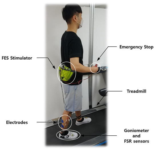
Figure 8.
Experimental setup for the treadmill test.
The range of motion of a joint during gait can be used as one way to assess the closeness of FES-induced walking to natural walking. Using a goniometer, the joint angle at the ankle was measured while the subject was walking on the treadmill. Performance of the DBE and TE were compared regarding the range of motion of the ankle joint during treadmill gait.
3.2.2. Isometric Contraction Tests
In the treadmill tests, sufficient rest time was given between test sessions to eliminate the effect of muscle fatigue on the experimental results. Another issue associated with muscle fatigue is safety. Treadmill walking with exhausted muscles can cause accidents, such as trips and falls, which may lead to injury. For safety reasons, we conducted isometric contraction tests, rather than treadmill tests, to compare the effects of FES envelopes on muscle fatigue.
For the isometric contraction tests, a customized device was built for this study, as shown in Figure 9. This device restricted the motion of the ankle joint and measured the joint torque in both plantar flexion and dorsiflexion. The joint torque could be calculated by the product of the force, measured by the load cell, and the distance between the load cell and ankle joint.
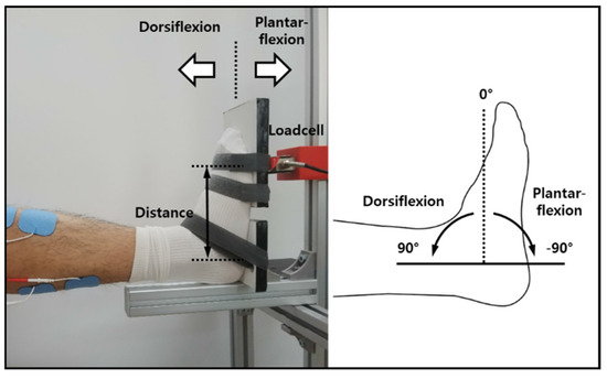
Figure 9.
Data acquisition device for isometric contraction tests.
Furthermore, one foot of the subject was strapped firmly to the device for isometric conditions, while the subject was sitting on a chair positioned in front of the device. The soleus of the strapped leg was stimulated by two different FES envelopes. Both FES envelopes were set to correspond to those for a gait of 3 km/h. The duration of the stimulation for isometric contraction was set to 5 min, which was long enough to cause FES-induced muscle fatigue.
To estimate muscle fatigue, surface EMG at the soleus was measured before and after FES stimulation. For the EMG measurement, each subject was asked to sustain 90% of their maximum voluntary isometric contraction (MVIC), where the MVIC for each subject was obtained before the isometric contraction tests. During 30 s of voluntary isometric contraction, the force was monitored by a loadcell. The EMG data were collected only when the force was maintained at a constant level.
FES-induced muscle fatigue could be estimated based on the changes in EMG before and after FES stimulation. As an index to assess muscle fatigue, changes in the median frequency (MDF) of EMG signals are commonly used [41]. A decrease in the MDF of the EMG signal indicated the amount of muscle fatigue. Performance of the DBE and TE were compared based on the decrease in MDF of the EMG signal before and after FES application.
4. Results
This section presents the experimental results of the treadmill and isometric contraction tests.
4.1. Treadmill Tests
Figure 10 shows a typical experimental result during treadmill gait at a walking speed of 3 km/h. Figure 10a plots the FES results for the TE and DBE, and Figure 10b compares the ankle joint angles generated by FES-induced muscle contractions in the cases of the TE and DBE. Figure 10b shows that the difference between the two joint angles was conspicuously between 55 and 90% of the gait cycle, which corresponded to the period from the maximum dorsiflexion in the stance phase to the mid-swing phase. The largest difference occurred at 70% of the gait cycle around the maximum plantarflexion of −5.969 and −8.203 for the TE and DBE, respectively. A larger plantarflexion of the DBE case suggested that the soleus was stimulated more effectively to produce a higher thrust force during the stance phase.
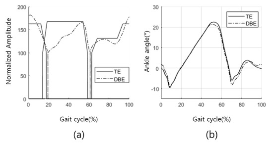
Figure 10.
Results of the treadmill tests. (a) Trapezoidal envelope and DNN-based envelope, and (b) corresponding ankle joint angles.
Figure 11 compares the maximum plantarflexion angles generated by the TE and DBE for five subjects at five different gait speeds. The results showed that the maximum plantarflexion by using DBE was larger than that of the TE with a statistically significant difference for most of the cases. The only exceptions were subjects 1 and 2 in a higher walking speed range. For subject 1, the maximum plantarflexion was larger with the TE at 4 and 5 km/h. Moreover, for subject 2, the maximum plantarflexion was larger with the TE at 4 km/h. However, differences in the exceptional cases were statistically insignificant.
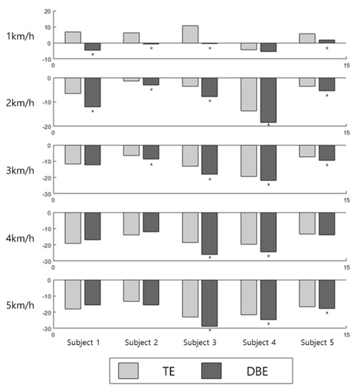
Figure 11.
Comparison of the maximum plantarflexion angles using the TE and DPE. (* Statistically significant difference with p < 0.05).
4.2. Isometric Contraction Tests
Figure 12 shows a typical plot of the MDF of EMG from the soleus before and after a 5 min isometric stimulation. The MDF was computed in the window with a data size of 1000 ms and a stride length of 500 ms. In addition, the MDF of each window is represented by the blank dots. The average MDF over one bout of contraction was indicated by the broken lines. A decrease in the MDF indicated the amount of FES-induced muscle fatigue after each stimulation.
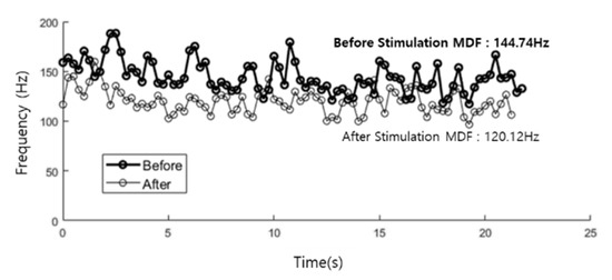
Figure 12.
MDF of EMG from the soleus before (black) and after (gray) 5 min contraction.
Figure 13 compares the reduction ratios of the MDFs of the EMG signals after each stimulation using the TE and DBE. Figure 13a shows that the reduction ratios of MDF in the soleus were smaller with the DBE for all subjects. This result demonstrates that FES-induced fatigue in the soleus could be significantly alleviated using the DBE. However, unlike in the soleus, the difference between the reduction ratios with the DBE and TE appears to be insignificant in the TA, as shown in Figure 13b.
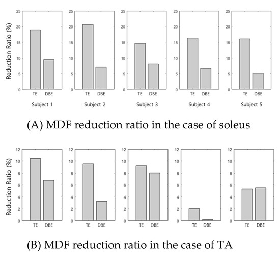
Figure 13.
Assessment results of the FES-induced fatigue. (A) MDF results of the soleus obtained before and after a 5 min stimulation of trapezoidal methods (left) and EMG-based methods (right), and (B) MDF results of the TA obtained before and after a 5 min stimulation of trapezoidal methods (left) and EMG-based methods (right).
5. Discussion
Performance of the DNN-based FES control algorithm was assessed experimentally and compared with a conventional FES control method with a trapezoidal envelope.
The results from the treadmill tests showed that the proposed method could generate larger ranges of motion in the push-off phase, as could be deduced from the maximum plantarflexion angles. Therefore, a larger thrust force could be produced with the proposed control system [42,43]. The treadmill tests were performed with five subjects at five different walking speeds (a total of 25 cases). There were three exceptional cases in which the maximum plantarflexion angles were larger with the TE, without statistical significance.
The results of isometric contraction tests indicated that FES-induced muscle fatigue in the soleus could be relieved by using the DNN-based FES control system, as a decrease of MDF in the EMG signals proved. However, an insignificant difference was observed in the muscle fatigue of the TA. A possible explanation would be that the TA was not required to produce much work during gait, compared with the soleus, which required a relatively large amount of work to generate push-off force.
The consideration of electric energy consumption was critical for the operation of battery-operated FES devices. Efficient FES control can decrease battery energy consumption to enable longer operation times. The time integral of the FES signal applied to the muscle can be used to indicate the electric energy consumption by the FES device. Figure 14 compares the time integrals of the FES signals generated by the TE and DBE over one gait cycle. The ratio of time integral with the DBE to that of the TE was computed for the FES from the soleus and TA at five different gait speeds. Therefore, the electric energy distribution by the DBE amounts to between 70 and 90% of that of the TE in the soleus. In the TA case, the ratio was nearly 100%, showing no advantage of the DBE over TE. Consequently, the electric energy consumption and FES-induced fatigue could be reduced by using the DBE, which is advantageous in the battery management of FES devices.
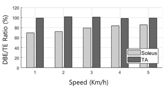
Figure 14.
Energy consumption ratio of DBE to TE.
6. Conclusions
In this study, we developed a novel gait rehabilitation system controlled by deep neural networks (DNNs) to provide functional electric stimulation (FES) for hemiplegic patients. The DNN-based controller computed amplitude of the FES on the paretic side based on the reference EMG and walking speed. The reference EMG was computed by functionalizing the EMG envelopes acquired from the treadmill gaits of healthy human subjects at various walking speeds. For the training data of the DNN, the EMG data and its corresponding joint torque were collected during isometric contraction tests with healthy human subjects.
The DNN algorithm (CNN–MLP) was implemented on the FES control system to stimulate the soleus and TA during gait, and its performance was assessed in comparison with a conventional method based on the trapezoidal FES envelope considering the range of motion of the ankle joint during treadmill gait, amount of FES-induced fatigue after isometric stimulation, and amount of energy consumption. The experimental results showed that the proposed FES control system could produce a larger range of motion with reduced muscle fatigue and less energy consumption by providing a smooth and timely assistive force compared to the conventional FES control method.
In addition, we aimed to develop an FES control algorithm to produce natural gait patterns in hemiplegic patients. By generating FES signals for the paretic side based on EMG data of healthy people, the burden on the muscles was effectively relieved while providing sufficient thrust force. Unlike conventional FES control methods with on/off step-like patterns or trapezoidal patterns, the smooth FES pattern can alleviate the impact on the muscles and electric energy consumption of the control device.
The developed FES control algorithm is expected to be effective for chronic hemiplegia with a low degree of disability. However, further clinical evaluations are necessary. Furthermore, the long-term effect of muscle fatigue induced by FES should be further studied to predict the operation time of FES and to alert the impending exhaustion of muscle activity for safe use of the developed system.
This study focused on the FES-induced ankle motion by stimulating the TA and the soleus only, while hemiplegia affects the motion of other joints. In our future work, we plan to apply the developed algorithm to the rehabilitation of knee and hip movements, as well as ankle movement. The FSR-based method used in this study is limited to coarse detection of the gait state, and additional sensors such as IMU can allow finer prediction of the gait phase. The recent development of the multi-pad electrode enables FES control of the muscles of various sizes. The novel sensor and FES technologies can be applied to the system developed in this study to extend its application to the rehabilitation of various lower extremity motor functions. The proposed FES control can be applied more effectively in combination with exoskeleton-type rehabilitation robots. Further studies are required to address redundant actuation issues with hybrid rehabilitation systems of FES and exoskeleton robots.
Author Contributions
Conceptualization, S.P., S.-J.K. and S.J.; methodology, S.P., S.-J.K. and S.J.; software, S.J.; Hardware, S.J., J.H.B.; validation, S.P., J.H.B.; formal analysis, S.J.; investigation, S.J.; data curation, S.J., J.H.B.; writing—original draft preparation, S.J.; writing—review and editing, S.J. S.P.; supervision, S.P.; project administration, S.P., S.-J.K.; funding acquisition, S.P., S.-J.K. All authors have read and agreed to the published version of the manuscript.
Funding
This work was supported by the National Research Foundation of Korea (NRF) Grant funded by the Korean Government (MSIT) (NRF 2016R1A5A1938472) and the work of S.P. was partially supported by the Sports Promotion Fund of Seoul Olympic Sports Promotion Foundation from Ministry of Culture, Sports and Tourism.
Institutional Review Board Statement
The study was conducted according to the guidelines of the Declaration of Helsinki, and approved by the Institutional Review Board of Korea University (KUIRB-2020-0277-01, 2020.10.08.).
Informed Consent Statement
Informed consent was obtained from all subjects involved in the study.
Data Availability Statement
Not Applicable.
Conflicts of Interest
The authors declare no conflict of interest.
References
- Glanz, M.; Klawansky, S.; Stason, W.; Berkey, C.; Chalmers, T.C. Functional electrostimulation in poststroke rehabilitation: A meta-analysis of the randomized controlled trials. Arch. Phys. Med. Rehabil. 1996, 77, 549–553. [Google Scholar] [CrossRef]
- Burridge, J.; Wood, D.; Taylor, P.; McLellan, D. Indices to describe different muscle activation patterns, identified during treadmill walking, in people with spastic drop-foot. Med. Eng. Phys. 2001, 23, 427–434. [Google Scholar] [CrossRef]
- Bohannon, R.W.; Larkin, P.A. Lower Extremity Weight Bearing Under Various Standing Conditions in Independently Ambulatory Patients with Hemiparesis. Phys. Ther. 1985, 65, 1323–1325. [Google Scholar] [CrossRef] [PubMed]
- Higginson, J.; Zajac, F.; Neptune, R.; Kautz, S.; Delp, S. Muscle contributions to support during gait in an individual with post-stroke hemiparesis. J. Biomech. 2006, 39, 1769–1777. [Google Scholar] [CrossRef] [PubMed]
- Kesar, T.M.; Perumal, R.; Reisman, D.S.; Jancosko, A.; Rudolph, K.S.; Higginson, J.S.; Binder-Macleod, S.A. Functional electrical stimulation of ankle plantarflexor and dorsiflexor muscles: Effects on poststroke gait. Stroke 2009, 40, 3821–3827. [Google Scholar] [CrossRef] [PubMed]
- Embrey, D.G.; Holtz, S.L.; Alon, G.; Brandsma, B.A.; McCoy, S.W. Functional Electrical Stimulation to Dorsiflexors and Plantar Flexors During Gait to Improve Walking in Adults with Chronic Hemiplegia. Arch. Phys. Med. Rehabil. 2010, 91, 687–696. [Google Scholar] [CrossRef] [PubMed]
- Daly, J.J.; Zimbelman, J.; Roenigk, K.L.; McCabe, J.P.; Rogers, J.M.; Butler, K.; Burdsall, R.; Holcomb, J.P.; Marsolais, E.B.; Ruff, R.L. Recovery of coordinated gait: Randomized controlled stroke trial of functional electrical stimulation (FES) versus no FES, with weight-supported treadmill and over-ground training. Neurorehabilit. Neural Repair 2011, 25, 588–596. [Google Scholar] [CrossRef] [PubMed]
- Werner, C.; Lindquist, A.R.; Bardeleben, A.; Hesse, S. The Influence of Treadmill Inclination on the Gait of Ambulatory Hemiparetic Subjects. Neurorehabilit. Neural Repair 2007, 21, 76–80. [Google Scholar] [CrossRef] [PubMed]
- Hesse, S.; Werner, C.; Bardeleben, A. Electromechanical gait training with functional electrical stimulation: Case studies in spinal cord injury. Spinal. Cord. 2004, 42, 346–352. [Google Scholar] [CrossRef] [PubMed]
- Hodkin, E.F.; Lei, Y.; Humby, J.; Glover, I.S.; Choudhury, S.; Kumar, H.; Perez, M.A.; Rodgers, H.; Jackson, A. Auto-mated FES for upper limb rehabilitation following stroke and spinal cord injury. IEEE Trans. Neural Syst. Rehabil. Eng. 2018, 26, 1067–1074. [Google Scholar] [CrossRef]
- Barbeau, H.; Norman, K.; Fung, J.; Visintin, M.; Ladouceur, M. Does neurorehabilitation play a role in the recovery of walking in neurological populations? Ann. N. Y. Acad. Sci. 1998, 860, 377–392. [Google Scholar] [CrossRef]
- Liberson, W.T.; Holmquest, H.J.; Scot, D.; Dow, M. Functional electrotherapy: Stimulation of the peroneal nerve synchronized with the swing phase of the gait of hemiplegic patients. Arch. Phys. Med. Rehabil. 1961, 42, 101–105. [Google Scholar]
- Chae, J.; Bethoux, F.; Bohinc, T.; Dobos, L.; Davis, T.; Friedl, A. Neuromuscular Stimulation for Upper Extremity Motor and Functional Recovery in Acute Hemiplegia. Stroke 1998, 29, 975–979. [Google Scholar] [CrossRef] [PubMed]
- Burridge, J.; Taylor, P.; Hagan, S.; Swain, I. Experience of Clinical Use of the Odstock Dropped Foot Stimulator. Artif. Organs 1997, 21, 254–260. [Google Scholar] [CrossRef] [PubMed]
- Lyons, G.M.; Sinkjaer, T.; Burridge, J.H.; Wilcox, D.J. A review of portable FES-based neural orthoses for the correction of drop foot. IEEE Trans. Neural Syst. Rehabil. Eng. 2002, 10, 260–279. [Google Scholar] [CrossRef] [PubMed]
- O’Keeffe, D.T.; Donnelly, A.E.; Lyons, G.M. The development of a potential optimized stimulation intensity envelope for drop foot applications. IEEE Trans. Neural Syst. Rehabil. Eng. 2003, 11, 249–256. [Google Scholar] [CrossRef]
- Sabut, S.K.; Sikdar, C.; Mondal, R.; Kumar, R.; Mahadevappa, M. Restoration of gait and motor recovery by functional electrical stimulation therapy in persons with stroke. Disabil. Rehabil. 2010, 32, 1594–1603. [Google Scholar] [CrossRef]
- Frigo, C.; Ferrarin, M.; Frasson, W.; Pavan, E.; Thorsen, R. EMG signals detection and processing for online control of functional electrical stimulation. J. Electromyogr. Kinesiol. 2000, 10, 351–360. [Google Scholar] [CrossRef]
- Ito, K.; Shioyama, T.; Kondo, T. Lower-Limb Joint Torque and Position Controls by Functional Electrical Stimulation (FES). In Complex Medical Engineering; Springer: Tokyo, Japan, 2007; pp. 239–249. [Google Scholar]
- Kim, J.-C.; Kim, K.-S.; Kim, S. Wearable sensor system including optical 3-axis GRF sensor for joint torque estimation in real-time gait analysis. In Proceedings of the 2014 IEEE/ASME International Conference on Advanced Intelligent Mechatronics, Besançon, France, 8–11 July 2014; IEEE: New York, NY, USA, 2014; pp. 112–117. [Google Scholar]
- Shao, Q.; Bassett, D.N.; Manal, K.; Buchanan, T.S. An EMG-driven model to estimate muscle forces and joint moments in stroke patients. Comput. Biol. Med. 2009, 39, 1083–1088. [Google Scholar] [CrossRef]
- Karavas, N.; Ajoudani, A.; Tsagarakis, N.; Saglia, J.; Bicchi, A.; Caldwell, D. Tele-impedance based assistive control for a compliant knee exoskeleton. Robot. Auton. Syst. 2015, 73, 78–90. [Google Scholar] [CrossRef]
- Rainoldi, A.; Melchiorri, G.; Caruso, I. A method for positioning electrodes during surface EMG recordings in lower limb muscles. J. Neurosci. Methods 2004, 134, 37–43. [Google Scholar] [CrossRef] [PubMed]
- Hahn, M.E. Feasibility of estimating isokinetic knee torque using a neural network model. J. Biomech. 2007, 40, 1107–1114. [Google Scholar] [CrossRef] [PubMed]
- Kordjazi, N.; Rahati, S. Gait recognition for human identification using ensemble of LVQ Neural Networks. In Proceedings of the 2012 International Conference on Biomedical Engineering (ICoBE), Penang, Malaysia, 27–28 February 2012; Institute of Electrical and Electronics Engineers (IEEE): New York, NY, USA, 2012; pp. 180–185. [Google Scholar]
- Li, Z.; Guiraud, D.; Andreu, D.; Benoussaad, M.; Fattal, C.; Hayashibe, M. Real-time estimation of FES-induced joint torque with evoked EMG. J. Neuroeng. Rehabil. 2016, 13, 60. [Google Scholar] [CrossRef] [PubMed]
- Mahdavian, M.; Arzanpour, S.; Park, E.J. Motion Generation of a Wearable Hip Exoskeleton Robot Using Machine Learning-Based Estimation of Ground Reaction Forces and Moments. In Proceedings of the 2019 IEEE/ASME International Conference on Advanced Intelligent Mechatronics (AIM), Hong Kong, China, 8–12 July 2019; Institute of Electrical and Electronics Engineers (IEEE): New York, NY, USA, 2019; pp. 796–801. [Google Scholar]
- Li, Z.; Guo, J.; Huang, D. Bidirectional joint torque prediction with EMG of multiple channels: Both agonist and antagonist muscles are necessary. In Proceedings of the 2016 Chinese Control and Decision Conference (CCDC), Yinchuan, China, 28–30 May 2016; IEEE: New York, NY, USA, 2016; pp. 4226–4231. [Google Scholar]
- Guachi, L.; Guachi, R.; Bini, F.; Marinozzi, F. Automatic Colorectal Segmentation with Convolutional Neural Network. Comput. Des. Appl. 2019, 16, 836–845. [Google Scholar] [CrossRef]
- Acharya, U.R.; Oh, S.L.; Hagiwara, Y.; Tan, J.H.; Adeli, H. Deep convolutional neural network for the automated detection and diagnosis of seizure using EEG signals. Comput. Biol. Med. 2018, 100, 270–278. [Google Scholar] [CrossRef] [PubMed]
- Baloglu, U.B.; Talo, M.; Yildirim, O.; San Tan, R.; Acharya, U.R. Classification of myocardial infarction with multi-lead ECG signals and deep CNN. Pattern Recognit. Lett. 2019, 122, 23–30. [Google Scholar] [CrossRef]
- Ordóñez, F.J.; Roggen, D. Deep Convolutional and LSTM Recurrent Neural Networks for Multimodal Wearable Activity Recognition. Sensors 2016, 16, 115. [Google Scholar] [CrossRef]
- Leonardis, D.; Chisari, C.; Bergamasco, M.; Frisoli, A.; Barsotti, M.; Loconsole, C.; Solazzi, M.; Troncossi, M.; Mazzotti, C.; Castelli, V.P.; et al. An EMG-Controlled Robotic Hand Exoskeleton for Bilateral Rehabilitation. IEEE Trans. Haptics 2015, 8, 140–151. [Google Scholar] [CrossRef]
- Trlep, M.; Mihelj, M.; Puh, U.; Munih, M. Rehabilitation Robot with Patient-Cooperative Control for Bimanual Training of Hemiparetic Subjects. Adv. Robot. 2011, 25, 1949–1968. [Google Scholar] [CrossRef]
- Bong, J.H.; Jung, S.; Park, N.; Kim, S.-J.; Park, S. Development of a Novel Robotic Rehabilitation System with Muscle-to-Muscle Interface. Front. Neurorobot. 2020, 14, 3. [Google Scholar] [CrossRef]
- Hanlon, M.; Anderson, R. Real-time gait event detection using wearable sensors. Gait Posture 2009, 30, 523–527. [Google Scholar] [CrossRef] [PubMed]
- Li, Z.; Hayashibe, M.; Fattal, C.; Guiraud, D. Muscle Fatigue Tracking with Evoked EMG via Recurrent Neural Network: Toward Personalized Neuroprosthetics. IEEE Comput. Intell. Mag. 2014, 9, 38–46. [Google Scholar] [CrossRef]
- Rueterbories, J.; Spaich, E.G.; Andersen, O.K. Gait event detection for use in FES rehabilitation by radial and tangential foot accelerations. Med. Eng. Phys. 2014, 36, 502–508. [Google Scholar] [CrossRef]
- Catalfamo, P.; Ghoussayni, S.; Ewins, D. Gait event detection on level ground and incline walking using a rate gyroscope. Sensors 2010, 10, 5683–5702. [Google Scholar] [CrossRef] [PubMed]
- Storm, F.A.; Buckley, C.J.; Mazzà, C. Gait event detection in laboratory and real life settings: Accuracy of ankle and waist sensor based methods. Gait Posture 2016, 50, 42–46. [Google Scholar] [CrossRef]
- Phinyomark, A.; Thongpanja, S.; Hu, H.; Phukpattaranont, P.; Limsakul, C. The usefulness of mean and median frequencies in electromyography analysis. In Computational Intelligence in Electromyography Analysis—A Perspective on Current Applications and Future Challenges; InTech Open: Rijeka, Croatia, 2012; pp. 195–220. [Google Scholar]
- Lewis, C.L.; Ferris, D.P. Walking with increased ankle pushoff decreases hip muscle moments. J. Biomech. 2008, 41, 2082–2089. [Google Scholar] [CrossRef]
- Judge, J.O.; Roy, B.; Davis, I.; Õunpuu, S. Step length reductions in advanced age: The role of ankle and hip kinetics. J. Gerontol. Ser. A Biol. Sci. Med. Sci. 1996, 51, M303–M312. [Google Scholar] [CrossRef]
Publisher’s Note: MDPI stays neutral with regard to jurisdictional claims in published maps and institutional affiliations. |
© 2021 by the authors. Licensee MDPI, Basel, Switzerland. This article is an open access article distributed under the terms and conditions of the Creative Commons Attribution (CC BY) license (https://creativecommons.org/licenses/by/4.0/).