Article

VAGADRONE: Intelligent and Fully Automatic Drone Based on Raspberry Pi and Android

VAGANET, 8 Rue des Frères Caudron, 78140 Vélizy-Villacoublay, France
*
Author to whom correspondence should be addressed.
These authors contributed equally to this work..
Appl. Sci. 2021, 11(7), 3153; https://doi.org/10.3390/app11073153
Submission received: 26 February 2021 / Revised: 24 March 2021 / Accepted: 29 March 2021 / Published: 1 April 2021
(This article belongs to the Special Issue Autonomous Flying Robots: Recent Developments and Future Prospects)

Abstract

:
Multirotor drones are widely used currently in several areas of life. Their suitable size and the tasks that they can perform are their main advantages. However, to the best of our knowledge, they must be controlled via remote control to fly from one point to another, and they can only be used for a specific mission (tracking, searching, computing, and so on). In this paper, we intend to present an autonomous UAV based on Raspberry Pi and Android. Android offers a wide range of applications for direct use by the UAV depending on the context of the assigned mission. The applications cover a large number of areas such as object identification, facial recognition, and counting objects such as panels, people, and so on. In addition, the proposed UAV calculates optimal trajectories, provides autonomous navigation without external control, detects obstacles, and ensures live streaming during the mission. Experiments are carried out to test the above-mentioned criteria.

1. Introduction

Recently, technological advances in computing, electronics, and telecommunications and their convergence in our daily lives have led to the emergence of new needs, especially with the widespread use of intelligent devices. Among these devices, unmanned aerial vehicles (UAVs), or drones, have been used in various missions. They were used for the first time towards the end of the First World War by the U.S. Army [1]. The idea was to guide piloted planes remotely without the pilot in the cockpit. Since then, UAVs have become the subject of innovation in various fields and for several types of missions. They have long been a military tool; however, in recent years, their use has been extended to the civilian domain. They present a promising solution for the most dangerous, delicate, and unsuitable missions for human pilots, which saves lives as they allow for the replacement of piloted planes and helicopters.
There are several designs for UAVs, among which the quadrotor offers real advantages such as:
  • Their reduced size and maneuverability allow them to fly in closed or open environments and close to obstacles, unlike conventional helicopters.
  • The can perform vertical take-off and landing.
  • This configuration is controlled by only varying the speed of the four engines.
However, the quadrotor has a number of drawbacks that still prevent it from becoming a leading technology among UAVs. Many works have addressed the problems of modeling, designing, and controlling such complex systems. Despite its four motors and stationary equilibrium, the quadrotor remains an underpowered and dynamically unstable system. The objective is to equip these quadrotors with more sensors and intelligence with the development of control algorithms to ensure their stability, as well as a certain degree of autonomy.
To the best of our knowledge, there is no prior work that has presented an intelligent and autonomous drone with Android as the operating system. The use of Android gives us a large array of applications for direct use by the drone depending on the context of the mission. Therefore, the main objective of this paper is to develop a quadrotor-type flying robot that ensures autonomous navigation and stability, as well as guarantees streaming in real time.
The remainder of this paper is organized as follows. Section 2 discusses related works. Section 3 presents the architecture of VAGADRONE such as the hardware and software used and the features of our UAV. Section 4 describes the simulation and experimental results in various scenarios. Finally, Section 5 provides some conclusions.

2. Related Works

Unmanned aerial vehicles (UAVs) are now widely used as autonomous flight systems for a multitude of uses and areas of intervention, such as military (surveillance, recording), urban (traffic), and recreational applications [2]. In addition, much research is currently being carried out in order to improve the airworthiness, the autonomy, the accuracy of measurement, and the smoothness of the movements of the aircraft [3]. Several works have been carried out on the control of UAVs based on optical flow. We can take the example of O.Dunkley and his colleagues [4], who already tried to fly a 25 g micro drone “quadcopter”, using the optical flow calculation method for visual odometry. Indeed, this test was done on an external computer. The size of miniature hardware also poses a limitation on the communication bandwidth, which can cause a noticeable delay. To achieve a maximum level of autonomy, it would be preferable and logical to decouple the UAV from any external dependence. Some researchers have promoted the use of EMDsensors and other 1D signal sensors to be able to build lightweight UAVs for autonomous flight. In the same context of optical flow-based control and the use of 1D flow sensors, Briod et al. [5] proposed the design of a 45 g quadcopter. They continued their research on a platform weighing 278 g that contained eight 1D flow sensors pointing in all directions. This allowed the quadcopter to hover in different crowded environments. The team of researchers achieved impressive results, but with several single-use sensors. They could only detect movement, which did not leave enough room to detect other variables essential for navigation. R. J. Moore et al. [6] implemented an optical flow algorithm with efficient results for a small lightweight (2 g) omnidirectional camera system on a 30 g helicopter. With a ring of eight low-resolution image chips (64 × 64 pixels), the UAV was able to calculate the optical flow. It performed the calculation of the edges, starting by compressing the images and calculating the displacement by the correspondence of blocks, which addressed translational optical flow. Vision calculations were performed on-board the helicopter at 10 Hz, but flight controls were calculated off-board. Despite the potential for a full on-board implementation, there was redundancy in the ratio of cameras to detected variables. A camera has the potential to detect flow in three directions; they used eight to detect only two (forward and lateral speed). Likewise, the optical flow can be exploited to detect obstacles; however, the UAV must be in constant motion. This is not important in case stereo vision is used for depth information.
In addition, H. Oleynikova and her team [7] developed a reactive avoidance controller for a quadrocopter (30 cm in diameter). They accumulated the values along the columns from the obtained stereo disparity map to obtain a summed disparity factor. Assuming the obstacles are vertical and long, these can be detected quickly. The stereo card was first computed over the entire image before it was accumulated into a vector. This has a significant impact on the amount of computation, which makes it less suitable for implementation on a smaller UAV.
In recent years, we have seen the appearance of a few prototypes using the Raspberry Pi, a single-card computer with an ARM processor whose very small size allows—theoretically—autonomy and a lighter weight. Contrary to FPGA, DSP, and GPU platforms, its datasheet shows that it does not require much power, and it is possible to use a small battery to power it [8]. Based on this study, we found that the DSP processor was not an appropriate platform for the design of higher performance UAVs and that the use of a GPU (although widespread for many image processing applications) was too limited in terms of portability. Finally, although FPGA technology seemed to be a good choice, the strong design constraints were a hindrance to its use in the context of the research project. Hence, the Raspberry Pi technology seemed particularly promising for a project like ours, which aimed to develop a highly autonomous UAV with as few embedded systems as possible. On the other hand, it seems that this miniaturization of the processor leads to new problems, particularly in terms of the range of functionalities allowed and the possibility of installing programming software (quantity of input/output controls and libraries, etc.). We therefore took a closer look at these technical difficulties by studying research work on the development of drones based on Raspberry Pi platforms. We first studied the work of [9], which focused on the development of the face detection functionality of a drone using a Raspberry Pi card, associated with a classifier algorithm and the OpenCV graphics library. This architecture was thus interesting in the context of our study, and in particular with regard to the performances obtained by the authors, i.e., >80% real detections, whatever the camera height. The authors thus demonstrated the interest in this card (lightness, fast design) for a UAV, to perform face detection in a precise and relatively reliable way. On the other hand, some performance drops were observed when the experimental conditions deteriorated, particularly in cases of real-time data transmission and for applications where the input frame rate was too high. After seeing the interest in integrating a Raspberry Pi card in a UAV architecture, we studied the technical possibilities associated with the operating system carried on the card. Today, the main OSs deployed on the Raspberry Pi are Unix and Linux, as the latter has been specially designed and optimized to run on a Raspberry Pi equipped with an ARM processor. However, many other OSs can be ported to the Raspberry Pi, but have limitations in memory capacity [10] and in updating or optimizing commands. Unlike the Android operating system, there are the disadvantages of not offering a touch screen, nor a wide choice of applications. Therefore, it seemed interesting to look into this system, but its deployment prototypes under Raspberry Pi are still limited to experimental installations, since no version has been optimized and there is no support for Raspberry Pi from Android application developers. The resulting unreliability is therefore a real difficulty to run applications, despite the continuous improvement of the hardware aspects of the Raspberry Pi 3 [11]. Another issue also concerns the development of video streaming functions, whose real-time mode is particularly difficult to develop under this operating system according to the information collected in the literature on this subject [12].

3. VAGADRONE

In the sequel, we present the architecture of our intelligent and autonomous drone and its features.

3.1. VAGADRONE: Architecture

This drone is able to ensure several missions, namely autonomous flight and obstacle detection. Therefore, its architecture must be defined in a way to ensure robust and high-performance operation during navigation. We thought about the conceptual choices for realization by which we approached the general architecture of the solution, the architecture of the UAV, and the architecture of the Linux server.

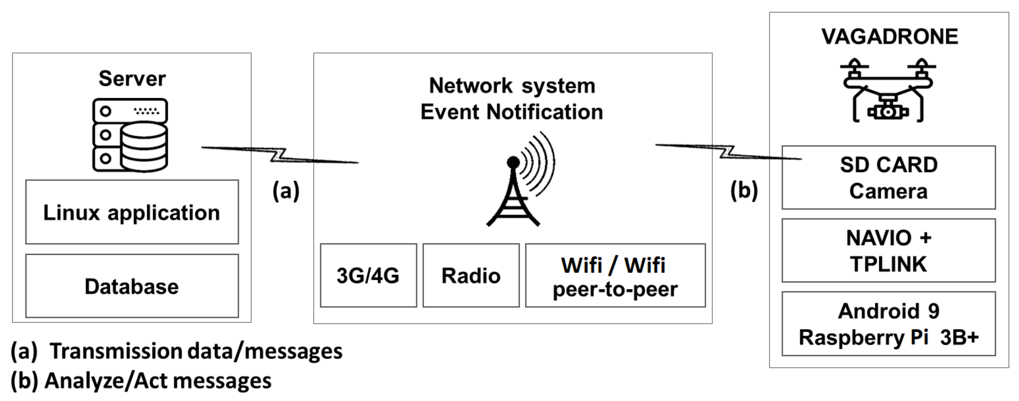
3.1.1. Global Architecture

In order to limit the scope of the work, it is necessary to cleverly determine a set of choices for the the realization. Our choice was based on a complex architecture composed of three main layers, which was used to model and present this system as a stack of three levels. Each component of the overall architecture had a well-specified description and characteristics; the role of each one is described as follows (see Figure 1):
  • VGADRONE: This is the main component of the solution. It is an intelligent and autonomous UAV based on the unique Pi 3B and Android 9 map allowing autonomous navigation and live streaming, etc. This component processes messages sent by the server in the form of several types of data (image, command, and text).
  • Network system/event notification: This is the component that ensures on the one hand a secure communication between the UAV and the server via three standards (radio, WiFi, 3G/4G); on the other hand, it allows standardizing the communication between the Android UAV and the Linux server. Actually, the standardization is based on a state machine allowing the synchronization between the different requests sent by the server and the notifications sent by the UAV to the server.
  • Server: It monitors and controls the UAV. It allows images to be sent to the UAV in order to launch a search session for individuals and objects and records the UAV’s navigation history.

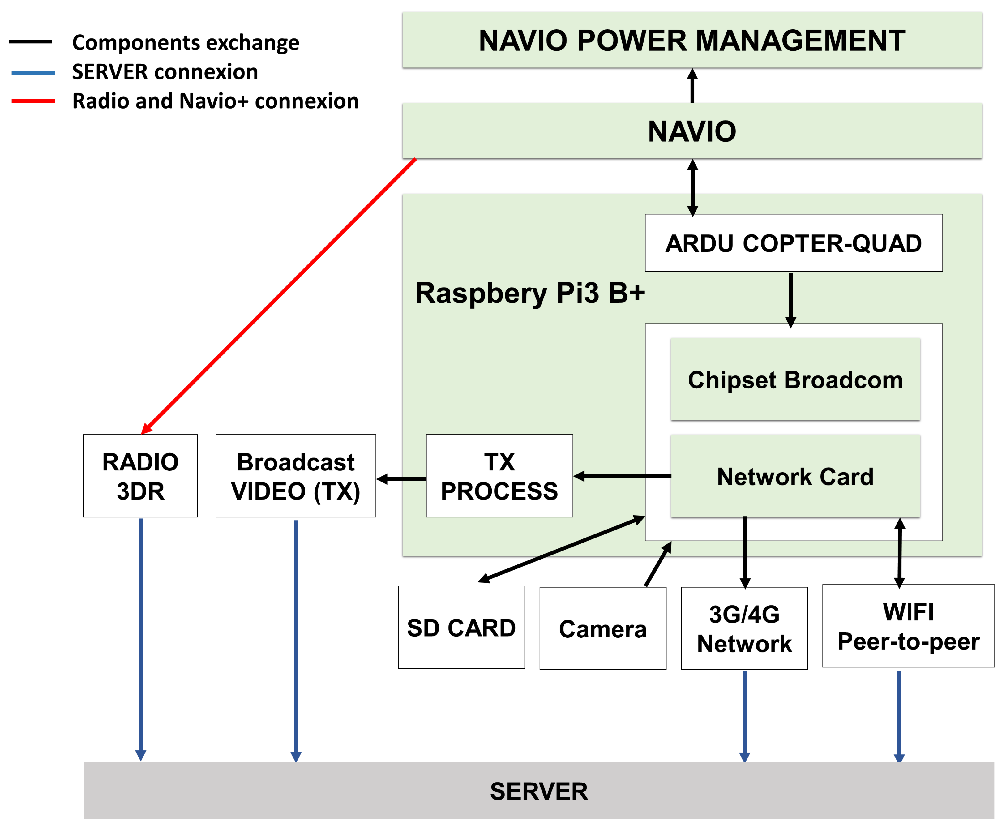
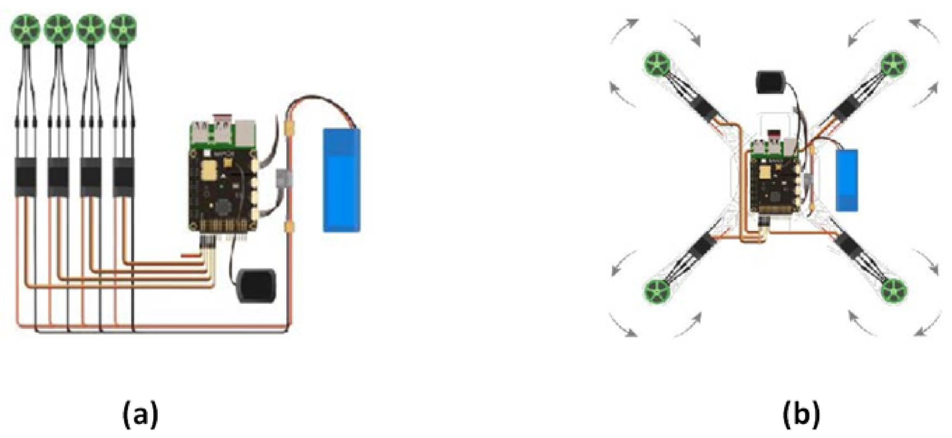
3.1.2. Hardware Architecture

The architecture and interactions of the different components that build the UAV are illustrated in Figure 2.
The UAV was composed of several modules to ensure automatic piloting, live streaming of captured videos, facial recognition, and connection with the server via the standards supported by the Raspberry Pi 3B+ network card. Each component of the hardware architecture had a well-specified description and characteristics, and the role of each one is described as follows:
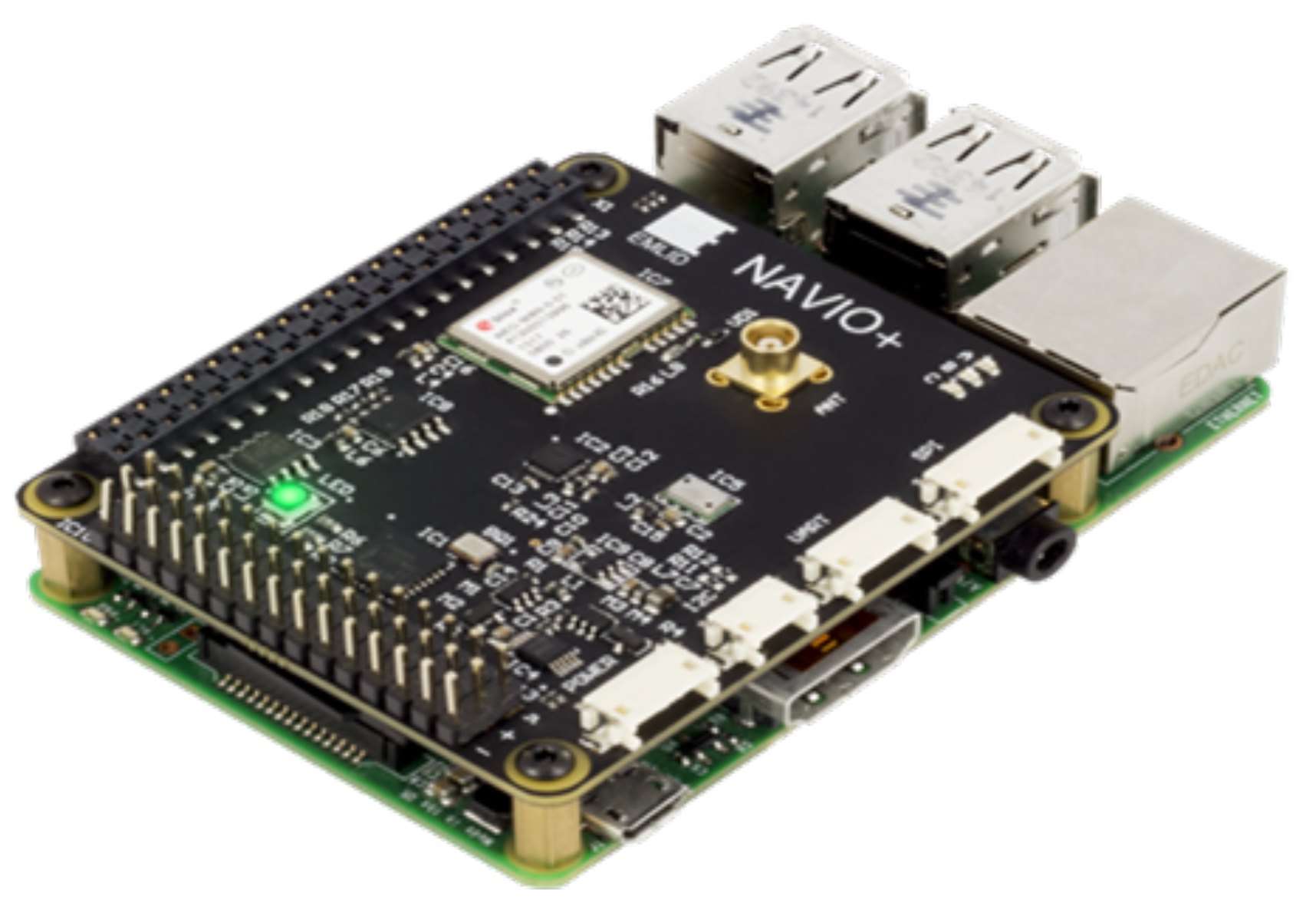
  • NAVIO+: Linux autopilot for the Raspberry Pi 3B+. It allows ensuring the autonomous navigation of the UAV via radio communication technology.
  • Ardu Copter-quad: This is the flight controller that allows the operation of multi-torque unmanned aircraft and traditional radio-controlled helicopters.
  • Smart card reader (4G Shield): This is the module that provides a 4G connection and offers ultra-fast Internet connectivity for live streaming.
  • Camera: This is the CSI interface camera that allows video streams to be recorded on the SD card built into the Raspberry Pi 3B+.

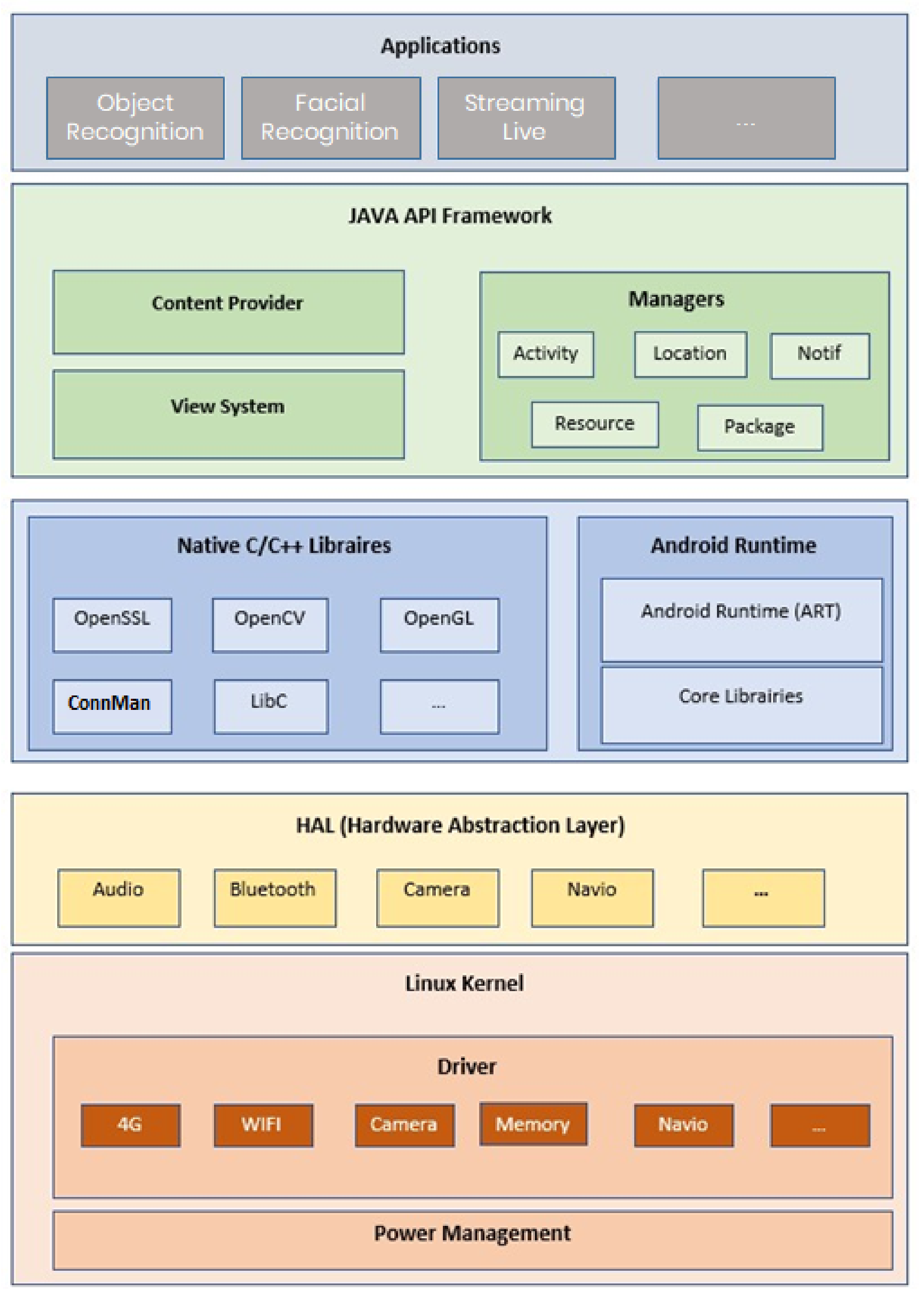
3.1.3. Software Architecture

The UAV’s software architecture is divided into several specific modules. Each module is also composed of sub-modules. The UAV’s software architecture is made up of five layers as shown in Figure 3:
  • The application layer acts as an interface between the UAV and the various functionalities required by the server.
  • The second layer, the Java API Framework, enables the acquisition and processing of the functionalities and access to programs. It is the application execution layer.
  • The third layer, Android Runtime, represents the OS execution environment.
  • The fourth layer is the abstraction layer between the kernel environment and the application environment.
  • Finally, the fifth pilot layer contains the drivers and the Linux kernel.
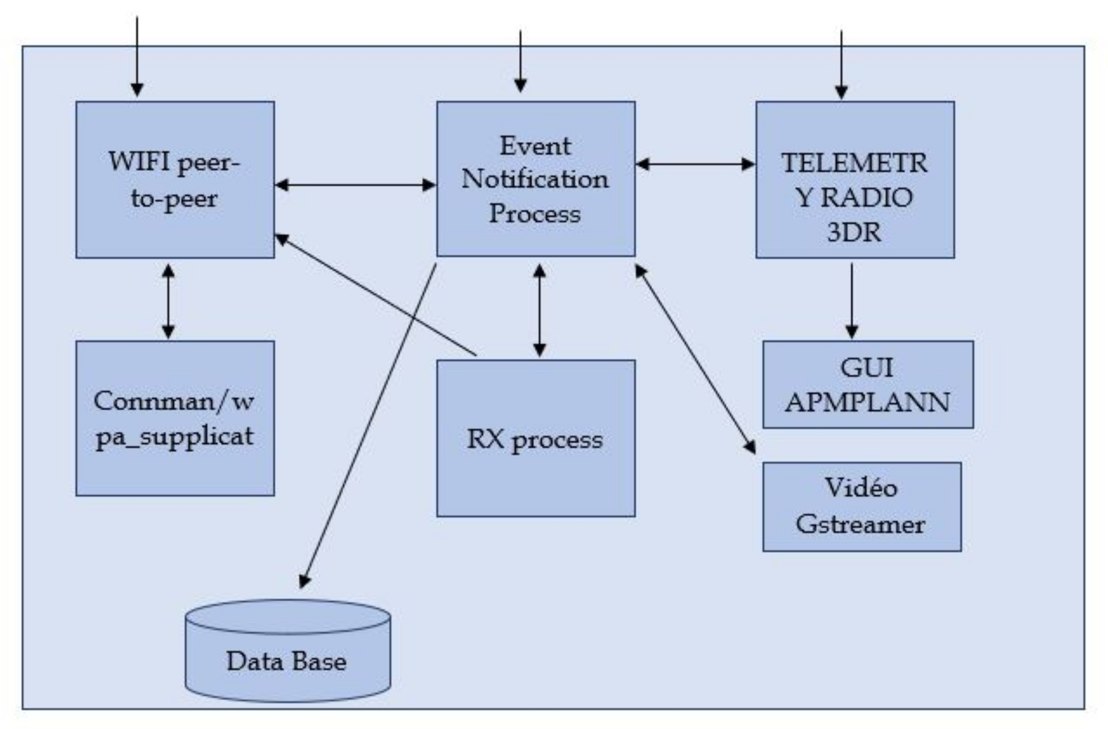
3.1.4. Server

The architecture of the server is simpler compared to the UAV architecture (see Figure 4). It is composed of several modules allowing the sending of images, the recording of the flight history, and the reading of the video streams sent by the UAV. The architecture of the server is defined by several components to ensure the proper functioning of the UAV. These components are:
  • WiFi peer-to-peer: This is the network card installed in the Linux Ubuntu server certified as 802.11 a/g/n to support high-speed communication between the server and the Raspberry Pi 3B+ card.
  • ConnMan/WPA supplicant: This is the network manager and the application to open a peer-to-peer connection between two devices.
  • Event notification process: This is a state machine allowing the sending and receiving of notifications between the UAV and the server.
  • Database: This is used to record the flight histories.
  • Video GStreamer: This is the module that decodes the video streams sent by the UAV.

3.2. VAGADRONE: Features

We studied the possibility of ensuring the autonomous navigation of the UAV without any external control (remote controls or another control source) while respecting real-time constraints and ensuring high-performance and robust navigation. Indeed, our UAV had to calculate an optimal path from WGS coordinates indicated by the Ubuntu Server in order to optimize battery consumption and increase operating performance to cover the search area. The main features of our UAV are:
  • The calculation of the optimal UAV navigation trajectory to cover a search area.
  • Automatic piloting of the Raspberry Pi 3B+ embedded Android from the Ubuntu server.
  • Detection of obstacles during the navigation of the UAV.
  • Live streaming of the mission
In the sequel, we detail the above-mentioned features. Indeed, we start with the preparation of the area to cover and the computation of the optimal trajectory

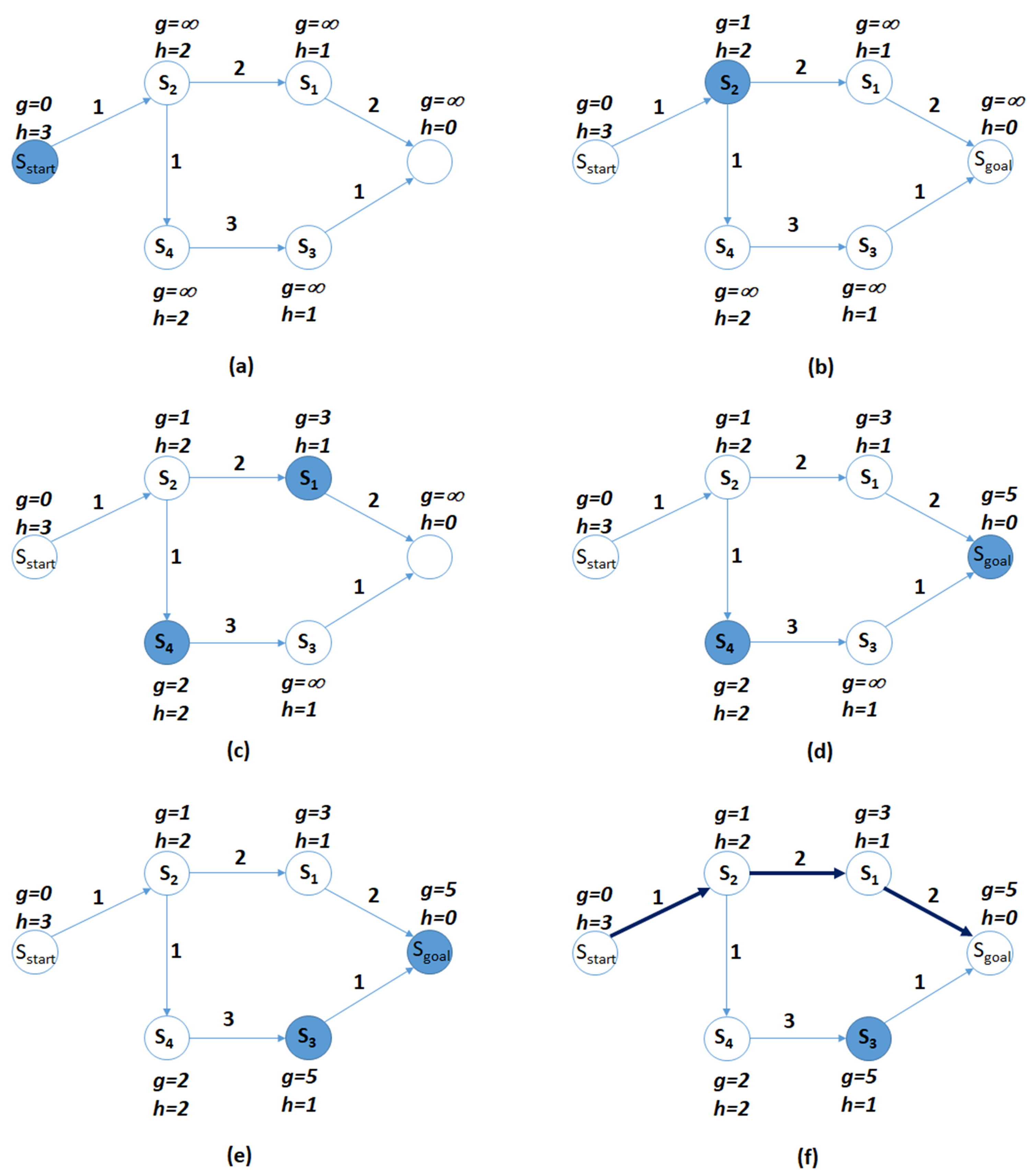
3.2.1. Optimal Trajectory Computation

We started by modeling the terrain as an oriented graph. However, instead of basing our graph on classical meshing, we opted for intelligent modeling, which allowed us to reduce the calculation time on this graph without losing precision (which is the classical problem with meshing). The modeling was based on the notion of a visibility graph and integrated the consideration of obstacles, danger zones, and the non-holonomy constraint of the aircraft that implies a maximum steering angle. The resulting graph was then cleaned to keep only the strict minimum necessary for trajectory calculation. The generation of the graph can require much computation time, but this generation is done only once before the planning stage and therefore does not affect the trajectory computation times. We also developed another graph containing less information and not taking into account the non-holonomy constraint. The advantage of the latter is that the time for its generation is very short. On the other hand, its use requires the implementation of a procedure to correct the trajectory to make it non-holonomous. This correction is feasible in the context of our missions, but not for all types of autonomous vehicles. Once this graph was generated, we proposed a procedure for calculating a shorter continuous non-holonomic path in a risky environment and in the presence of obstacles. Since the graph used already integrated all the constraints, we modeled the problem as a search for a shorter path with a resource constraint (the resource was the amount of risk allocated). The results were very satisfying since the routes were non-holonomic trajectories that respected all constraints. Moreover, the computation time was very short. For the cases of the simplified graph, we created a procedure for correcting the trajectory to make it non-holonomic. All non-holonomy calculations were based on the curves of Dubins [13]. The UAV was allowed to evolve in 3D space. At first, we discretized it in a regular way to model it (Figure 5). The resulting graph was then easily implemented with MATLAB.
The results were loaded into a matrix whose coefficients represented the “state” as mentioned in Table 1.
The objective of the first part of the problem was to find a path between the start (0) and the goal (1) by avoiding obstacles (−1). There are many algorithms that would allow us to find, if it exists, a path connecting two points on this graph. One of the best known is the Dijkstra algorithm and A* algorithm.
In this part, we illustrate the tests performed to validate and verify the behavior of the A* algorithm in order to compute an optimal path from the WGS coordinates sent by the server. Figure 6 shows a scenario to find the optimal path from Point 1 ( s s t a r t ) to the endpoint ( s g o a l ) while passing from several nodes s 1 to s 4 .
To find the optimal path, we had to take into consideration the length of the path between linked nodes g and the distance between the current node and sgoal, denoted by h, which verifies:
h = S R s a > 0 ; s s g o a l
if h ( s 1 ) < h ( s 2 ) s 1 is the nearest to s g o a l ( h ( s g o a l ) = 0 ). Nodes with bold outlines are OPEN. After sgoal is found, the path is shown in bold.
To illustrate the advantages of this algorithm, we used the previous example of a map without obstacles, with sstartin (100, 50) and sgoal in (200, 50). We noticed that the path was found much faster (100 iterations compared to 20,000 with the Dijkstra algorithm).
We present the function:
k ( s ) = g ( s ) + h ( s )
where g ( s ) , as was mentioned before, is the length of the path from s s t a r t to the current node s and h ( s ) is the heuristic, i.e., an estimate of the distance between node s and s g o a l . This function determines the order in which the nodes are reached using the A* algorithm. In order to accelerate the search towards s g o a l , we could modify the expression of k ( s ) in order to bring more weight to the heuristics. We note:
k ( s ) = g ( s ) + ϵ . h ( s )
ϵ = 0 corresponds to a non-oriented search, and ϵ > = 1 defines the weighted A* algorithm.
This algorithm significantly reduces the number of iterations required to obtain a solution in many cases. However, we no longer have a guarantee of the optimality of the solution returned by the algorithm. Nevertheless, the use of a heuristic that does not overestimate the cost of going from the current node to the s g o a l node allows us to have control over the “sub-optimality” of the path between sstart and s g o a l . Indeed, for such a heuristic (Euclidean distance for example), we have:
l e n g t h P a t h ϵ > 1 < ϵ × L e n g t h P a t h O p t i m a l

3.2.2. Automatic Control of the UAV

In this part, we integrate the NAVIO+ map under the Raspberry Pi 3B+ in order to improve the performance and to find a solution for the navigation constraint encountered while computing the optimal trajectory.
The NAVIO+ card is an extension of the Raspberry Pi 3B+. It is a very powerful card and has a variety of sensors and input/output for communication with the exterior. The NAVIO (Figure 7) card has several components namely:
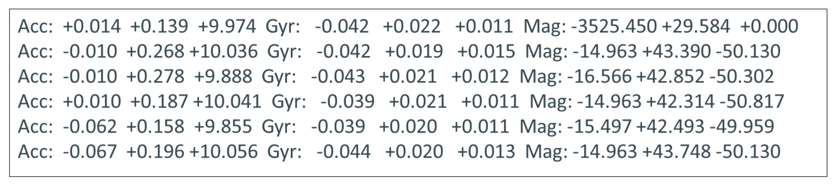
  • Dual IMU: MPU-9250: This has all the necessary sensors for the knowledge of the angular position and linear acceleration of our system. It integrates an accelerometer, a gyroscope, and a magnetometer with very high sensitivities, which helped us greatly in the automation of the UAV.
  • GNSS receiver: NEO-M8M: This is the GPS module integrated in the NAVIO+ card. This module communicates with the card via an SPI link, sends messages containing location information, and receives configuration data.
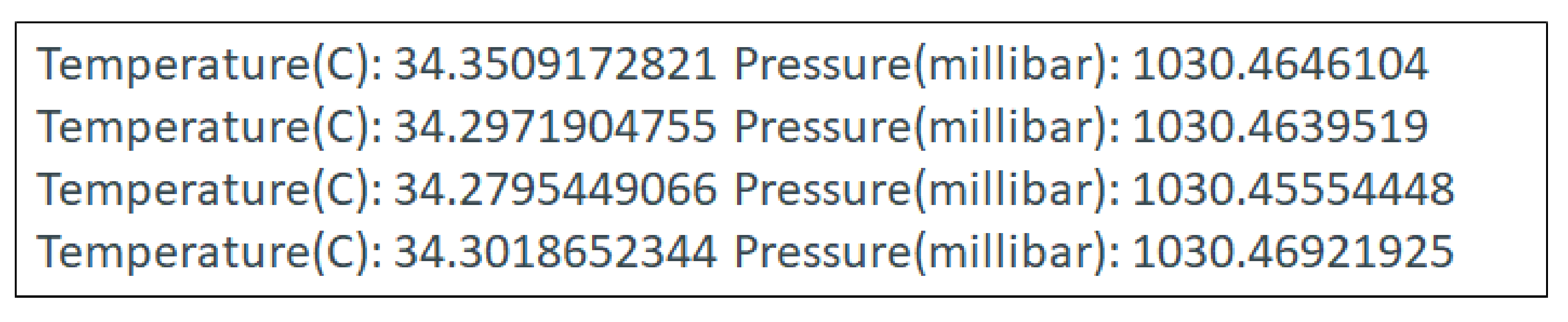
  • High-resolution barometer: MS5611: This is a high-resolution barometer with a resolution of 10 cm for accurate UAV altitude values.
  • Extension ports: The NAVIO+ card has a variety of interfaces available for possible extensions, namely ADC, I2C, and UART interfaces.

3.2.3. Obstacle Detection while Navigating

Flying autonomously can be ensured if our drone is capable of detecting obstacles. For this purpose, we chose to install and integrate the component IR E18-D80NK obstacle detection sensor under the Raspberry Pi 3B+. It helps to detect obstacles by measuring the angle of reflection of the emission of modulated IR.
The E18-D80NK infrared sensor allowed us to detect the presence of obstacles with great precision and speed because this detection could act as an interruption in our software for the modification of our trajectory when our UAV was navigating. The 80 cm were sufficient for the change of our trajectory at the time of the detection of an obstacle.

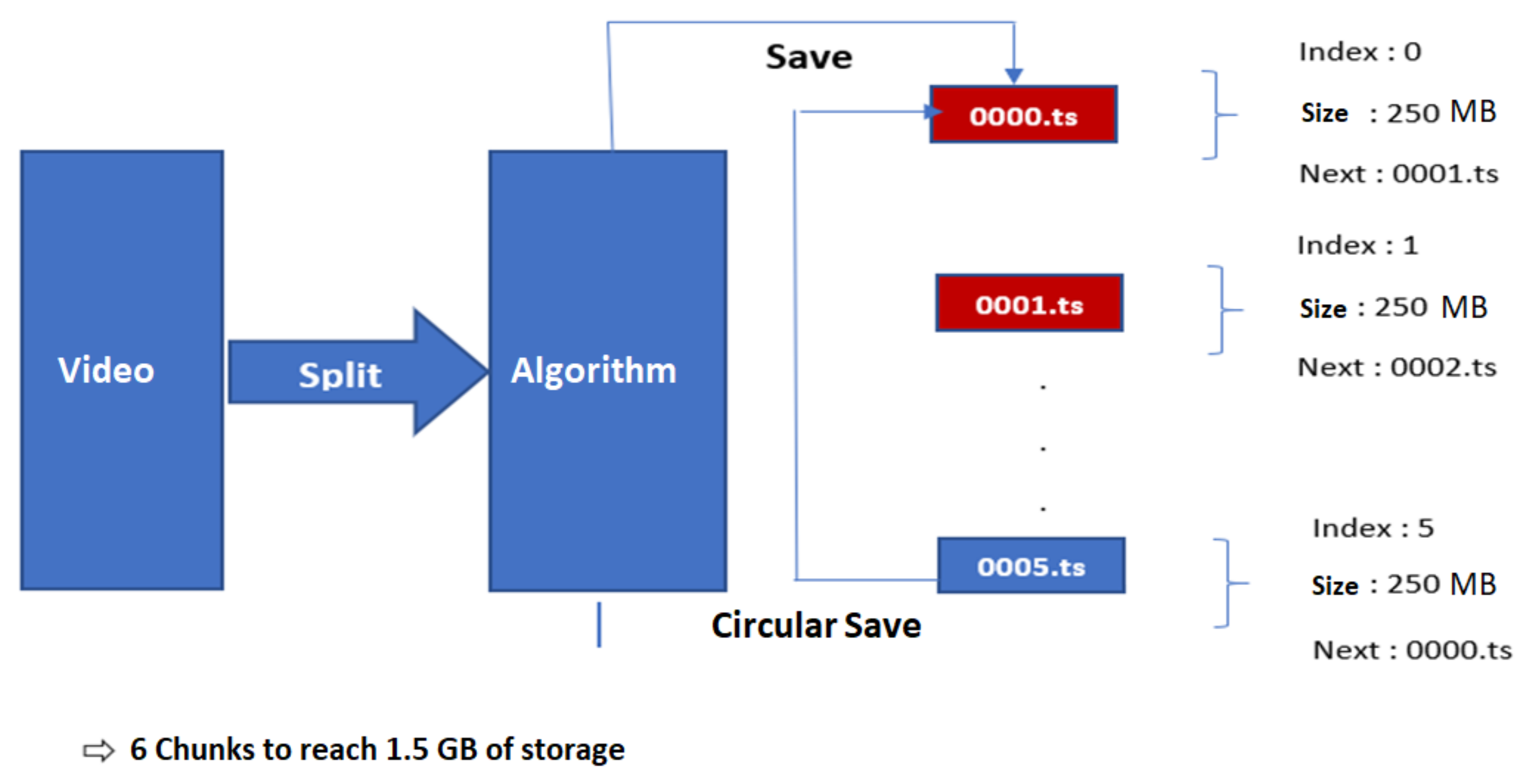
3.2.4. Live Streaming

We tried sharing video captured by the camera integrated under the Ubuntu UAV and server, respecting security and memory constraints. The UAV should broadcast the video stream captured by the camera to the server instantaneously and in real time, taking into account the two constraints: on the one hand, securing the data exchanged between the two devices against fraudsters and, on the other hand, optimizing the use of memory, given that the Raspberry Pi B3+ is limited in terms of capacity (16 GB in memory).
We implemented a video stream recording mechanism. It was optimized in terms of real-time consumable memory by the media-sharing algorithm between the UAV and the server.
The problems that can be encountered as a result of the memory constraint are:
  • Latency in the operation of the UAV’s navigation module (navigation, obstacle detection, etc.).
  • The problem of real-time image processing by the facial recognition algorithm.
  • Macroblocks in captured videos.
Following these constraints and problems encountered for the storage of data in the SD card, we implemented an intelligent solution for recording video in the Raspberry Pi 3B+. This solution consisted of storing the video chunks in a cyclic way in order to respect the memory area dedicated to storage, as shown in Figure 8.
In order to have a good video quality and optimized stream without having macroblocks or black screens, which are due to memory overflow or data consumption from empty memory space, we implemented an algorithm using circular buffers. The circular buffer allowed managing the data flow in real time in an optimized way.

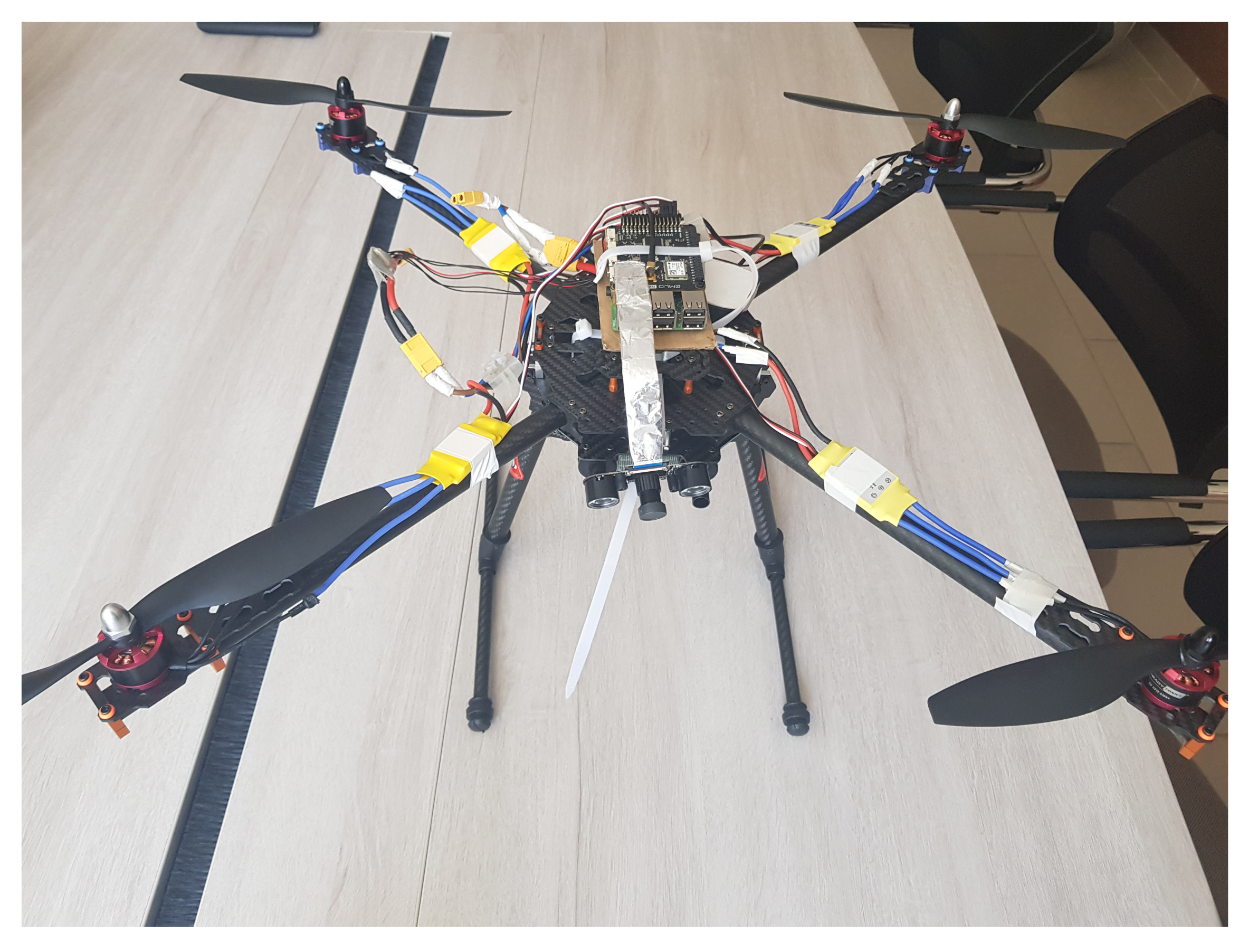
4. Experiments and Results

In this section, we detail the results of various experiments to evaluate the performance of real-time applications using VAGADRONE (Figure 9).
For the experiments, we used our VAGADRONE, which was a quadcopter composed of:
  • A Raspberry Pi 3B+ board based on an ARM Cortex-A53 64 bit, quad-core 1.2 GHz processor. We chose this board for several reasons:
    • The size of the Raspberry Pi 3B+ is small, and so, the card is perfectly suited to be used in a drone.
    • The Raspberry Pi 3B+ is very powerful. It includes a 4 core processor, a 1 GB processor, and 1 GB of RAM, so one can install a real operating system like Android and run Android and applications that can be used during the realization of the project.
  • The NAVIO2 flight controller described in the previous section.
  • A camera attached to the Raspberry Pi 3 Model B, by means of a Pin 15 ribbon cable, via the dedicated 15 pin serial interface (CSI) camera. It supports 1080 p × 720 p with 60 frames per second thanks to the 5 MP sensor. This module was intended to be used in the context of a broadcast. It should allow monitoring its environment in real time and saving a history of images if necessary.
  • Ultrasonic sensors (E18-D80NK infrared sensor).
  • Brushless motors Readytosky 920KV defined by several characteristics:
    • KV refers to the number of turns per minute per Volt. A motor with a very high KV will fall into the category of very high speed, but low torque motors, while a motor with a low KV will fall into the opposite category. The chosen motor was a Readytosky Motor with a KV of 920 powered by a battery that provides about 11.1 V; our motor would run at 11.1 × 920 = 10.212 rpm.
    • The voltage that the motor can withstand is generally a range expressed as a number S, 1 S being equivalent to 3.7 V. In the case of the motor we chose, its operation must be with batteries of type 3 S.
    • Another element to take into account is the number of amperes that the motor will consume at full load, because this value will be used to choose the electronic speed control (ESC).
  • The ESC driver. This controller allows managing the motor rotation speed.
  • A LiPo battery.
The assembly of our drone followed the NAVIO2 manual published by Emlid. Figure 10 shows the wiring diagram (a) and the image of the components with the chassis (b).
We started by testing the computation of the optimal path to reach the zone of the mission. For this purpose, we applied the weighted A* algorithm. Thus, we modified the weight ϵ and computed the number of iterations to find the best trajectory. The results for different ϵ are given in the following Table 2.
Thus, in our case, the use of the A* algorithm allowed reducing the number of visited cells by two compared to the Dijkstra algorithm to obtain an optimal path. If there was no constraint in terms of the distance to travel, but an obligation to find a solution as quickly as possible, the weighting on the heuristic could be increased (epsilon = 1.5 and 5). Setting ϵ to 1.5 means tolerating a sub-optimality of 50% on the distance traveled to reach the goal. In this example, we can see that the UAV would take half the time to obtain a path that would be, in our example, only 5.92% longer.
Next, we tested the automatic control of the UAV. Before assembling our system, we had to perform unit tests and complete measurements for all our sensors in order to properly parameterize the UAV. For each module, we developed test binaries from which we made measurements to understand the real behavior of each sensor.
To test the IMU module, the MPU9250 driver was used, and the NAVIO/MPU9250.h file contained the methods for communicating with this circuit. We tested it, and it gave us results in real time as follows (Figure 11).
We also tested the Barometer MS5611, a pressure sensor that also integrates a temperature sensor for calibration purposes. This sensor has a resolution of 10 cm.
As shown in Figure 12, the temperature values were high compared to the temperatures in the laboratory, and this was due to the heating of the Raspberry Pi card.
The NAVIO card is very powerful. The level of abstraction of the library helped us quickly develop our prototype. The overweight problem was solved with this card (23 g after assembly with the Raspberry Pi 3B+).
We also tested the live streaming module of our VAGADRONE system. In this part, we test the performance of the solution of using circular buffers to optimize the recording of videos in the SD card. The objective of this test was to verify the proper functioning of the solution and its optimization with respect to memory consumption. The test procedure:
-
We launched a recording of a video with the CSI interface camera under the Raspberry Pi 3B+.
-
Under the terminal of the Raspberry Pi 3B+, we ran the command below to launch the program to generate the circular buffer.
/ u s r / b i n / gen_circular_buffer / t m p / v_ 109845689345. t s
The duration of the video v_109845689345.tswas 15.36 min with a size of 5 GB. Table 3 illustrates the result found after the binary launch of the circular buffer generation solution.
As shown in Table 3, this algorithm recorded every 25 s of video captured by the camera in the form of an HD chunk (.ts) transport stream. With this solution, we ensured the optimization of the memory used by the video recording while keeping the performance of the UAV operation.
We tested the behavior of our VAGADRONE while navigating in four different areas (a park, a small village, a dense village, and half village/half park). We ran the test using a well-charged drone for 1000 s in four different zones. Figure 13 shows the battery performance test result as a function of time.
It was quite clear that the drone in Zone 4 (park) discharged slowly when compared to other zones. This was due to the density of obstacles present in Zones 1, 2, and 3 compared to Zone 4. Thus, our VAGADRONE consumed more battery to avoid obstacles.

5. Conclusions

In this paper, we proposed VAGADRONE, an autonomous and intelligent drone. The contribution of this paper was the cross-compilation of Android with Linux. Android allowed us to achieve many applications depending on the mission of the UAV such as object identification, facial recognition, and counting objects such as panels, people, and so on. On the other hand, VAGADRONE had many features that ensured autonomous navigation. It calculated the optimal UAV navigation trajectory to cover a search area. It had automatic piloting from the Raspberry Pi 3B+ with Android embedded from the Ubuntu server. It detected obstacles during its navigation, and it offered live streaming while respecting the constraints of the memory, real-time performance, and security.

Author Contributions

Conceptualization, methodology, software, investigation, validation, formal analysis, and resources, S.B. and M.M.; writing—original draft preparation, writing—review and editing, and visualization, A.B.; supervision and project administration, I.G. and N.J. All authors read and agreed to the published version of the manuscript.

Funding

This research received no external funding.

Conflicts of Interest

The authors declare no conflict of interest.

References

  1. Gregory, D. From a view to a kill: Drones and late modern war. Theory Cult. Soc. 2011, 28, 188–215. [Google Scholar] [CrossRef]
  2. Mandal, S.; Maheta, K.; Kumar, V.; Prasad, M.S. Control of UAV Using GSM Technology. In Proceedings of the International Conference on Modern Research in Aerospace Engineering; Springer: Singapore, 2016; pp. 77–85. [Google Scholar]
  3. Venkatesh, G.A.; Sumanth, P.; Jansi, K.R. Fully autonomous UAV. In Proceedings of the 2017 International Conference on Technical Advancements in Computers and Communications (ICTACC), Melmaurvathur, India, 10–11 April 2017; pp. 41–44. [Google Scholar]
  4. Dunkley, O.; Engel, J.; Sturm, J.; Cremers, D. Visual-inertial navigation for a camera-equipped 25g nano-quadrotor. In Proceedings of the IROS2014 Aerial Open Source Robotics Workshop, Chicago, IL, USA, 27 June–11 July 2014; p. 2. [Google Scholar]
  5. Briod, A.; Zufferey, J.C.; Floreano, D. Optic-flow based control of a 46g quadrotor. In Proceedings of the Workshop on Vision-based Closed-Loop Control and Navigation of Micro Helicopters in GPS-denied Environments, IROS 2013 (No. CONF), Tokyo, Japan, 7 November 2013. [Google Scholar]
  6. Moore, R.J.; Dantu, K.; Barrows, G.L.; Nagpal, R. Autonomous MAV guidance with a lightweight omnidirectional vision sensor. In Proceedings of the 2014 IEEE International Conference on Robotics and Automation (ICRA), Hong Kong, China, 31 May–5 June 2014; pp. 3856–3861. [Google Scholar]
  7. Oleynikova, H.; Honegger, D.; Pollefeys, M. Reactive avoidance using embedded stereo vision for mav flight. In Proceedings of the 2015 IEEE International Conference on Robotics and Automation (ICRA), Seattle, WA, USA, 26–30 May 2015; pp. 50–56. [Google Scholar]
  8. Noh, J.; Cho, K.; Kim, S.; Kim, W.; Jeong, J.; Sang, J.; Gong, M. Development of application for guidance and controller unit for low cost and small UAV missile based on smartphone. J. Korean Soc. Aeronautical Space Sci. 2017, 45, 610–617. [Google Scholar]
  9. Daryanavard, H.; Harifi, A. Implementing Face Detection System on UAV Using Raspberry Pi Platform. In Proceedings of the Iranian Conference on Electrical Engineering (ICEE), Mashhad, Iran, 8–10 May 2018; pp. 1720–1723. [Google Scholar]
  10. Bekaroo, G.; Santokhee, A. Power consumption of the Raspberry Pi: A comparative analysis. In Proceedings of the 2016 IEEE International Conference on Emerging Technologies and Innovative Business Practices for the Transformation of Societies (EmergiTech), Balaclava, Mauritius, 3–6 August 2016; pp. 361–366. [Google Scholar]
  11. Kurniawan, A. Getting Started with Android Things for Raspberry Pi 3; PE Press: Riverside, CA, USA, 2017. [Google Scholar]
  12. Pampattiwar, K.; Lakhani, M.; Marar, R.; Menon, R. Home automation using raspberry pi controlled via an android application. Int. J. Curr. Eng. Technol. 2017, 7, 962–967. [Google Scholar]
  13. Dubins, L.E. On curves of minimal length with a constraint on average curvature, and with prescribed initial and terminal positions and tangents. Am. J. Math. 1957, 79, 497–516. [Google Scholar] [CrossRef]
Figure 1. Global architecture of the proposed system.
Applsci 11 03153 g001
Figure 2. The hardware architecture of VAGADRONE.
Applsci 11 03153 g002
Figure 3. The software architecture of VAGADRONE.
Applsci 11 03153 g003
Figure 4. The server architecture.
Applsci 11 03153 g004
Figure 5. Discretization of the 3D space.
Applsci 11 03153 g005
Figure 6. A* algorithm (a) after initialization (b) after the expansion of S s t a r t (c) after the expansion of S 2 (d) after the expansion of S 1 (e) after the expansion of S 4 (f) after the expansion of S g o a l .
Applsci 11 03153 g006
Figure 7. NAVIO+ card.
Applsci 11 03153 g007
Figure 8. Example of the circular buffer algorithm.
Applsci 11 03153 g008
Figure 9. VAGADRONE.
Applsci 11 03153 g009
Figure 10. The assembly of the VAGADRONE components (a) the wiring diagram (b) the components with the chassis.
Applsci 11 03153 g010
Figure 11. Results of the IMU test. Acc: linear accelerations on the x, y, and z axes, respectively. Gyr: the angular velocities respectively around the x, y, and z axes. Mag: data provided by the magnetometer indicating the orientation of the UAV.
Applsci 11 03153 g011
Figure 12. Results of the barometer test.
Applsci 11 03153 g012
Figure 13. Battery performance test over time.
Applsci 11 03153 g013
Table 1. Discretization of the space.
ValueState
−1Obstacle
0Start
1Goal
2Crossable cell
Table 2. Optimal path for different ϵ using the weighted A* algorithm.
Epsilon011.55
Number of iterations145723628
Length of the path23.899523.899525.313729.7990
Table 3. Results of the circular buffer solution.
Chunk (.ts)Duration (s)Size (MB)Comment
First cycle (recorded content of 1500 MB)
0000.ts25250
0001.ts25250
0002.ts25250
0003.ts25250
0004.ts25250
0005.ts25250
Second cycle (recorded content of 1500 MB)
0000.ts25250Removed old content
0001.ts25250Removed old content
0002.ts25250Removed old content
0003.ts25250Removed old content
0004.ts25250Removed old content
0005.ts25250Removed old content
Third cycle (recorded content of 1500 MB)
0000.ts25250Removed old content
0001.ts25250Removed old content
0002.ts25250Removed old content
0003.ts25250Removed old content
0004.ts25250Removed old content
0005.ts25250Removed old content
Fourth cycle (recorded content of 500 MB)
0000.ts25250Removed old content
0001.ts25250Removed old content
Publisher’s Note: MDPI stays neutral with regard to jurisdictional claims in published maps and institutional affiliations.

