Article

A Two-Round Optimization Design Method for Aerostatic Spindles Considering the Fluid–Structure Interaction Effect

1
School of Mechatronics Engineering, Harbin Institute of Technology, Harbin 518057, China
2
School of Astronautics, Harbin Institute of Technology, Harbin 518057, China
3
School of Electrical Engineering and Automation, Harbin Institute of Technology, Harbin 518057, China
*
Authors to whom correspondence should be addressed.
Appl. Sci. 2021, 11(7), 3017; https://doi.org/10.3390/app11073017
Submission received: 12 March 2021 / Accepted: 25 March 2021 / Published: 28 March 2021
(This article belongs to the Special Issue Gas Bearings: Modelling, Design and Applications)

Abstract

:
The fluid–structure interaction (FSI) effect has a significant impact on the static and dynamic performance of aerostatic spindles, which should be fully considered when developing a new product. To enhance the overall performance of aerostatic spindles, a two-round optimization design method for aerostatic spindles considering the FSI effect is proposed in this article. An aerostatic spindle is optimized to elaborate the design procedure of the proposed method. In the first-round design, the geometrical parameters of the aerostatic bearing were optimized to improve its stiffness. Then, the key structural dimension of the aerostatic spindle is optimized in the second-round design to improve the natural frequency of the spindle. Finally, optimal design parameters are acquired and experimentally verified. This research guides the optimal design of aerostatic spindles considering the FSI effect.

1. Introduction

Aerostatic spindles are widely employed in various kinds of precision equipment for their distinct advantages of ultra-high precision, negligible friction, and wide rotating speed range [1]. However, the drawbacks of low capacity, low stiffness, and poor high-speed stability restrict their possible application significantly. Many factors have a great impact on the overall performances of aerostatic spindles, such as the geometrical parameters of the aerostatic bearing, the supply pressure, the rotating speed, and the restrictor type, etc. Hence, it is difficult to optimize the design parameters of aerostatic spindles comprehensively.
Numerous research studies have been conducted to facilitate the design of aerostatic bearings by investigating the impact of the air film geometrical dimensions on their static performance [2,3]. Li et al. [4] numerically studied the performances of the orifice-type restricted aerostatic thrust bearings with varying geometrical parameters based on computation fluid dynamics, and the effect tendency of geometrical parameters to the bearing performances was acquired. Belforte [5] and Du et al. [6] investigated the stiffness, load-carrying capacity (LCC) of aerostatic thrust bearings and journal bearings with pressure-equalizing groove (PEG), and found that the PEG can enhance the static performance of aerostatic bearing dramatically.
Many studies also have been carried out on the optimal design approach of air bearings [7,8,9]. Wang et al. [10] proposed an optimal design approach based on a genetic algorithm, and a hybrid selection scheme was adopted when selecting the mating groups, which is more efficient. Federico et al. [11,12] optimized the orifice diameter, orifice position, and orifice number of inherently compensated rectangular aerostatic pad bearings based on a multi-objective genetic algorithms optimization approach. To optimize the design parameters and supply pressure of a rectangular aerostatic thrust bearing, Nikhil et al. [13] proposed a Pareto optimization method to avoid the variation of the optimal results with different initial populations; the trial points are therefore distributed in the design space uniformly.
However, the structural deformation caused by pressurized air film was neglected in the aforementioned researches. Since the performance of the aerostatic bearings is significantly impacted by the air film thickness, this phenomenon may induce great error when calculating the performance of the aerostatic, and the initial design requirements may not be satisfied by the actual performance of the aerostatic bearing. This phenomenon is especially dramatic in the design of aerostatic bearings with high stiffness and high LCC, such as the spindle of fly cutting machine tools, rotary tables, etc., and has drawn increasing attention in recent years [14,15]. Lu et al. [16,17] numerically and experimentally investigated the performance of an air spindle considering the fluid–structure interaction (FSI) effect. They found that the LCC curve declines slightly due to the FSI effect, and the axial stiffness declines with the decrease of the thrust thickness plate. In a study by Gao et al. [18], the performance of an aerostatic spindle was investigated by a two-way FSI simulation model. It showed that the air film thickness changes about 7.65 μm due to the structure deformation and the stiffness of the spindle declines about 34%.
According to the above literature review, it can be seen that the design of aerostatic bearing includes the design of the air bearing parameters and the design of the crucial dimensions of the solid parts. Even though many optimal design approaches of air bearings have been proposed, the FSI effect is seldom considered, and the crucial structural dimensions are usually decided empirically. Therefore, the aerostatic spindle cannot be optimized comprehensively from its LCC, volume flow rate (VFR), stiffness, natural frequency, etc.
To overcome this issue, a two-round optimization design method for the aerostatic spindle with consideration of the FSI effect is proposed in the current study. The design parameters for the aerostatic bearing and the solid parts can be optimized by the proposed approach. As an application case, an aerostatic spindle is optimized. The impact of the crucial parameters of air film and the structural dimensions on the performances of the aerostatic spindle are investigated based on the finite element method (FEM). The performance of the aerostatic spindle is enhanced from the aspects of LCC, VFR, stiffness, natural frequency, etc. Furthermore, experiments were implemented to validate the reliability of the calculation results.

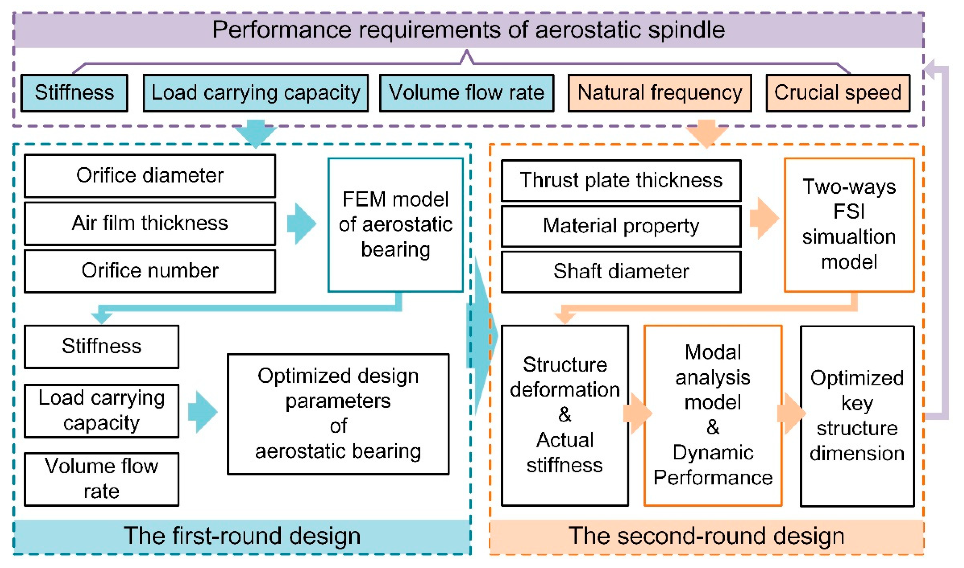
2. A Two-Round Optimization Design Method of Aerostatic Spindles Considering the FSI Effect

According to the existing design philosophy of aerostatic bearings [19,20,21], the design of air bearing is usually first carried out based on its performance requirements and design restrictions, and then the crucial solid parts are designed empirically based on the dimensions of air film. The elastic deformation of crucial parts caused by high air pressure and its impact on the overall performance of the aerostatic spindle are ignored. However, when the FSI effect is considered, the design of the aerostatic spindle consists of the design of the geometrical parameters of air bearing and the design of key structural dimensions. Both aspects impact the overall performance of the spindle system significantly. To facilitate the optimal design of aerostatic spindles considering FSI, a two-round optimization design method is proposed in this research, as shown in Figure 1. Its basic idea is to optimize the geometrical parameters of aerostatic bearing and the key structural dimensions of solid parts sequentially so that the static and dynamic performance of the spindle system can be optimized comprehensively.
In the first-round design stage, the static performances of the aerostatic bearing are improved by optimizing its geometrical parameters. The FEM model of aerostatic bearing is built in this stage. Then, the influence of the crucial design parameters (such as the orifice diameter, the air film thickness, and the orifice number) on the static performance of the aerostatic bearing can be acquired. Finally, the optimized design parameters for air bearing design can be acquired by selecting a good combination of LCC, stiffness, and volume flow rate (VFR).
In the second-round design stage, the static and dynamic performances of the aerostatic spindle are further investigated with consideration of the FSI effect. A two-way FSI simulation model is built to calculate the structural deformation of the spindle and its impact on the static performance of the aerostatic bearing. The crucial structural dimensions that greatly influence the structural rigidity and weight of solid components are analyzed. Furthermore, to clarify the effect of structure dimension on the natural frequency of the spindle, modal analysis with varying structure dimensions is carried out, and finally, the optimal structural dimensions are acquired.
In the following sections, the optimal design of an aerostatic spindle is implemented as a case study to elaborate the detailed procedures of the proposed two-round optimization design method.

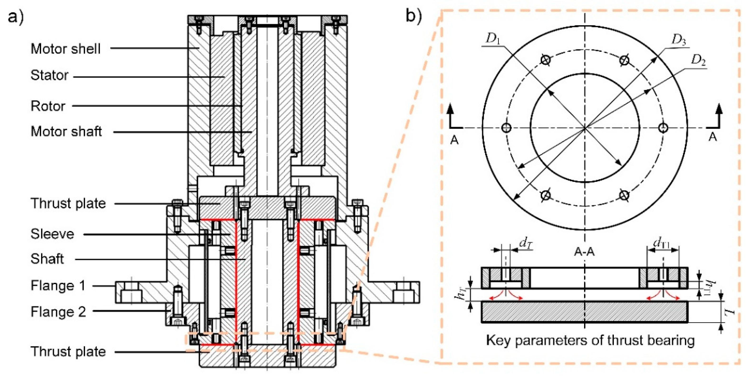
3. The Configuration of an Aerostatic Spindle

Figure 2a presents the configuration of an aerostatic spindle that is employed in an ultra-precision fly cutting machine tool. Its rotating parts consist of a shaft and two thrust plates. Two air thrust bearings and a radial bearing are adopted to separate the rotating parts from the shaft sleeve and resist the external load. In ultra-precision fly cutting machining, the axial direction of the spindle is the error-sensitive direction. Therefore, the axial vibration and tilt vibration of the rotating parts has a significant impact on the machined surface quality [22]. It indicates that enhancing its axial stiffness and angular stiffness is beneficial to reduce its vibration amplitude and the machined surface quality.
Figure 2b demonstrates the geometrical parameters of the aerostatic thrust bearing. The restrictor of aerostatic thrust bearings is a pocketed orifice-type restrictor. The inner diameter of the thrust bearing is D1, and the outside diameter of the thrust bearing is D3. There are n orifices distributes equally along the circumferential direction of the thrust bearing, and the diameter is D2. d and h are the diameter of the orifice restrictor and the thickness of air film, respectively. d1 and h1 are the diameter and the depth of the recess, respectively. Table 1 shows the initial values of these parameters.

4. The First-Round Optimal Design of Aerostatic Thrust Bearings

The static performances of an aerostatic bearing are greatly impacted by the geometrical parameters of the orifice-type restrictor, such as the orifice diameter, the air film thickness, and the orifice number. Therefore, its performances can be improved by optimizing these parameters. In this section, a numerical model of the aerostatic thrust bearing is built first based on the FEM. Additionally, then, the impact of the above three parameters on the static performances of aerostatic thrust bearing is calculated based on the FEM model. Finally, the static performances of the aerostatic thrust bearing are improved by optimizing these three design parameters.

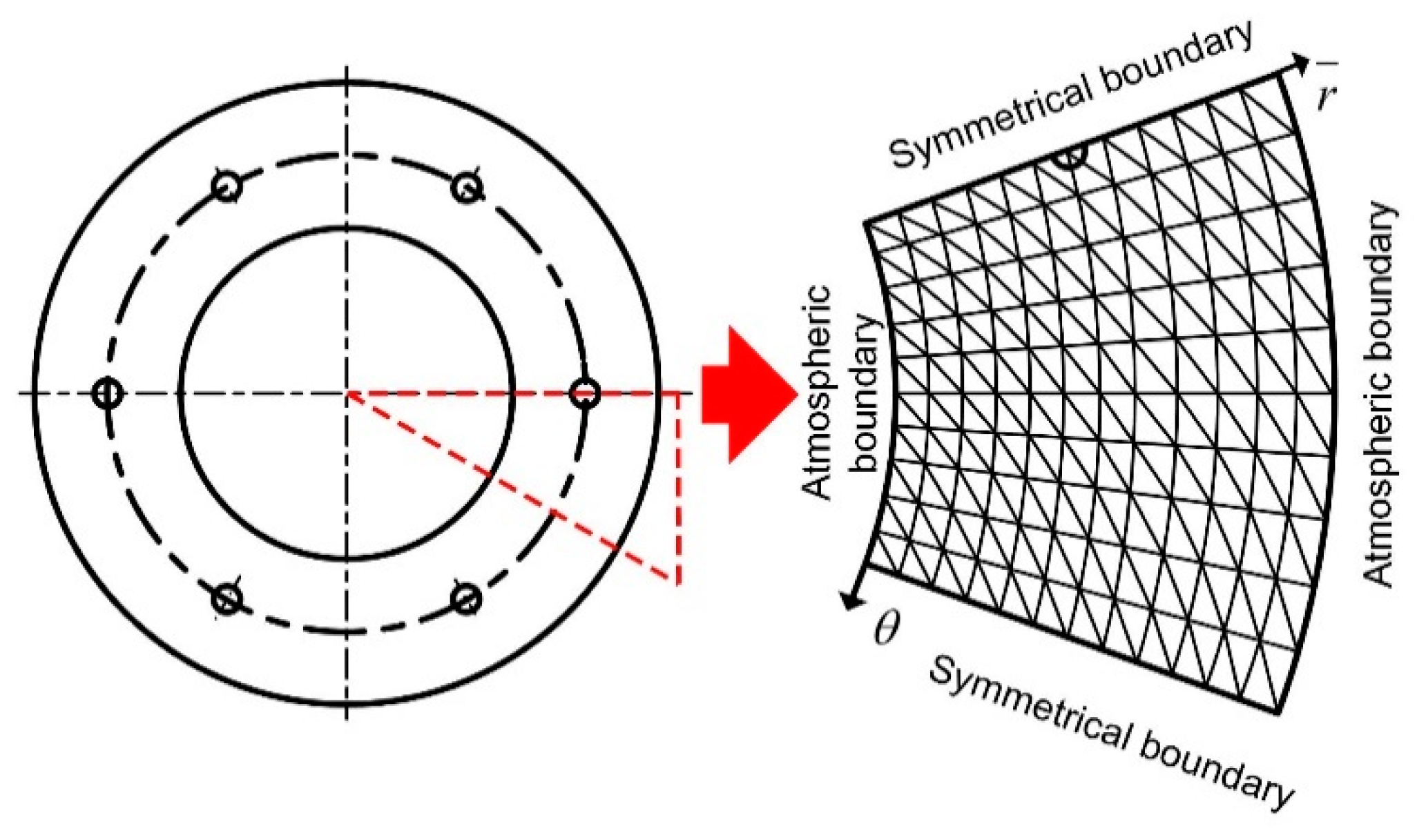
4.1. FEM Modeling of Aerostatic Bearings

The flow status of an orifice restrictor is simplified as the compressible flow through an ideal nozzle, and the orifice is simplified as a point. When the air flows through the orifice, the air pressure drops from Ps to Pd immediately. Considering the difference between the actual mass flow rate of the orifice restrictor and the ideal theoretical mass flow rate, a constant called discharge coefficient Cd = 0.8 is introduced to correct the mass flow rate. The mathematical models for calculating the theoretical mass flow rate of the orifice restrictor are Equations (1) and (2) [20].
m = C d A p s 2 ρ a p a ψ s ,
ψ s = k 2 2 k + 1 ( k + 1 ) / ( k 1 ) 1 / 2 ; p d p s β k k k 1 p d p s 2 / k p d p s ( k + 1 ) / k ; p d p s > β k β k = ( 2 / ( k + 1 ) ) ( k + 1 ) / k
where A = πd2/4 is the cross-section area of orifice, Pa is the atmosphere pressure, ρa is the density of air under standard state, ψs is flow rate function, and k is the specific heat ratio of air.
The fluid domain of the aerostatic thrust bearing is described using the governing equation in the cylindrical coordinate system [20] below:
ξ ¯ h 3 ¯ p 2 ¯ ξ ¯ + θ h 3 ¯ p 2 ¯ θ + r 2 ¯ Q ¯ δ i = Λ r ¯ θ ( h ¯ p ¯ ) ,
where h ¯ is the dimensionless thickness of air film, p ¯ is the dimensionless pressure, ξ ¯ is the dimensionless coordinate in the radial direction, r is the coordinate in the radial direction, and θ is the coordinate in the circumferential direction. Q ¯ is the mass flow rate factor of the orifice restrictor. δi is a constant coefficient with a value of 1 or 0 (in the computational domain where there is an orifice, it equals 1; otherwise, it equals 0.) Λ is the dimensionless bearing number.
h ¯ = h h m , r ¯ = r r 0 , ξ ¯ = ln r ¯ , p ¯ = p p s , Q ¯ = 24 η r 0 2 p a h m 3 p s 2 ρ a ρ v ˜ , Λ = 12 η v θ 2 r 0 h m 2 p s ,
where h is the thickness of air film. r0 is the characteristic length, hm is the reference air film thickness, p is the gas pressure distribution function, ρ is the air density, η is air dynamic viscosity, v ~ is the velocity of orifice gas flow, and vθ2 is the velocity components in the circumferential direction. In this paper, the performance of aerostatic thrust bearing is analyzed under motionless conditions, and therefore, Λ = 0.
The pressure square function is defined as follows:
f ¯ = p 2 ¯ ( ξ ¯ , θ ) = f ¯ ( ξ ¯ , θ ) .
Taking the pressure square function f ¯ as the variable, the functional Φ can be constructed based on Equation (3) as follows:
Φ ( f ¯ ( ξ ¯ , θ ) ) = Ω h 3 ¯ 2 f ¯ ( ξ ¯ , θ ) ξ ¯ 2 + f ¯ ( ξ ¯ , θ ) θ 2 Q f ¯ ( ξ ¯ , θ ) δ i d ξ ¯ d θ
where Ω denotes the computational domain of the air film. It has been mathematically proved that, under certain boundary conditions, the extremum of Equation (6) can only be acquired by a certain pressure square function f ¯ that is the solution of Equation (3).
The triangular finite element is employed to solve Equation (6) in this paper. i, j, m are the three nodes of triangular finite elements. The interpolation function of triangular finite element is defined as
f = N e T f e
f e = f i f j f m T
N e = N i N j N m T ,
where fe represents the pressure square of the nodes. Ne is the shape function of the triangular element, which can be calculated by Equation (10).
N i = 1 2 Δ e a i + b i θ + c i ξ ¯ , ( i = i , j , m )
a i = θ j ξ m ¯ θ m θ j b i = ξ ¯ j ξ m ¯ c i = θ m θ j ,
where Δe is the area of the triangular element. By changing the subscripts of Equation (11) in the order of i, j, m sequentially, and Nj and Nm can be obtained.
By substituting Equation (7) into Equation (6) and applying it to the finite elements of the entire computational domain, Equation (12) can be derived as follows:
Φ ( f ) = e = 1 m 1 2 Δ e h 3 ¯ x ¯ N e T f e 2 + z ¯ N e T f e 2 d ξ ¯ d θ e = 1 m Δ e Q ¯ f d ξ ¯ d θ δ i .
The partial derivative with respect to f should be zero to obtain the solution of Equation (6); thus, we can obtain Equation (13). The solution of Equation (13) is the pressure square function f ¯ , which makes the functional Φ reach the extremum.
Φ f i = e Δ i c i c e T + b i b e T f e Δ e h 3 ¯ d ξ ¯ d θ / ( 2 Δ e ) 2 k 1 μ r m ˙ r δ i = 0 ( i = 1 , 2 , , n ) .
Additionally, Equation (13) can be rewritten in the matrix form as follows:
K F = T ,
where F = [f1 f2 fn]T is a column vectors with n×1 dimensions. T is composed of three types of elements: 0, K 1 m ˙ r μ r and c i ( k ) c j ( k ) + b i ( k ) b j ( k ) × Δ k h 3 ¯ d ξ ¯ d θ / 2 Δ k 2 . m ˙ r is the real mass flow rate of the orifice restrictor. K is a square matrix with n×n dimensions, and its elements can be acquired by
K i j = e Δ i Δ j c i c j + b i b j h 3 ¯ d ξ ¯ d θ ( 2 Δ e ) 2 .
Then, the LCC, the stiffness, and the VFR of the aerostatic thrust bearing can be calculated by the equations below. The LCC of the aerostatic thrust bearing is the sum of the integration of the pressure on each element. Then, the stiffness of the aerostatic thrust bearing can be calculated by Equation (17). The VFR can be acquired by Equation (18).
W L C C = p s r 0 2 e = 1 m Δ e p ¯ d ξ ¯ d θ
K stiffess = W L C C ( h + Δ h ) W L C C ( h ) Δ h
Q VFR = m / ρ .
Figure 3 presents the FEM model of the aerostatic thrust bearing. Since the thrust air film is symmetric in the circumferential direction, a basic sector is built and the periodic boundary conditions are employed to save calculation time. The computational domain is equally divided into nθ parts along the circumference direction, while it is divided into nξ parts along the radial direction.

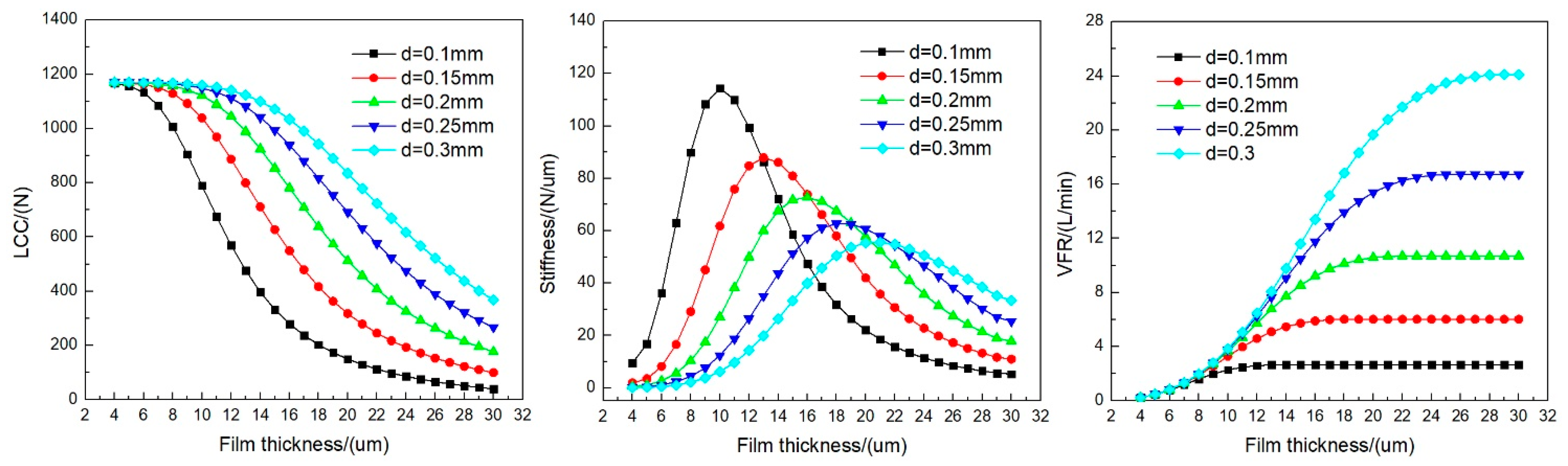
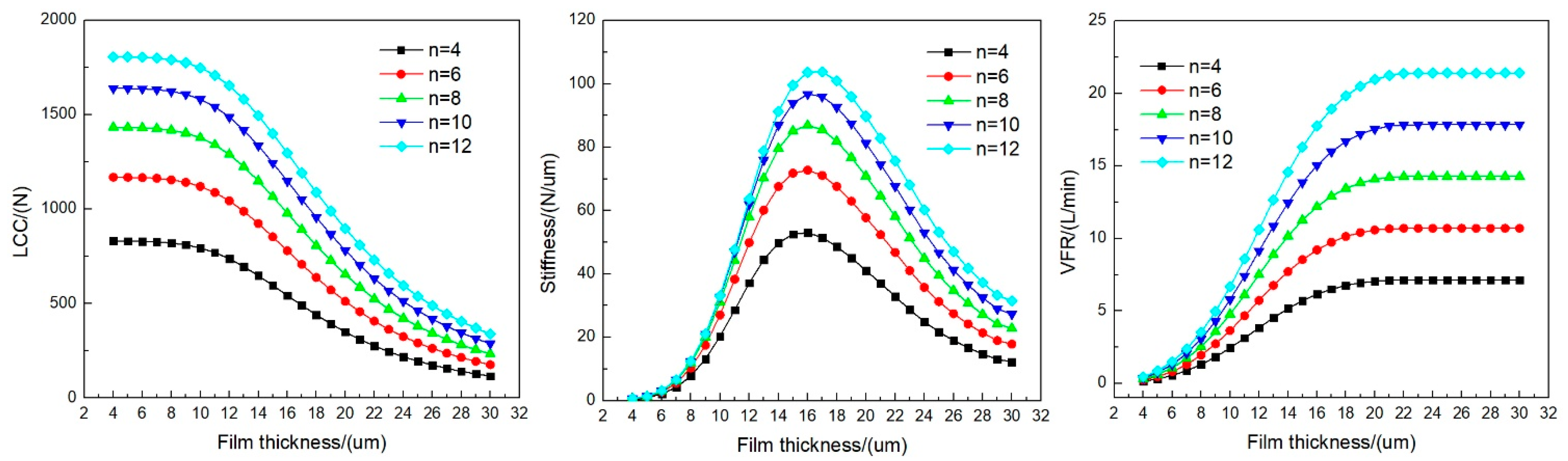
4.2. Optimal Design of the Geometrical Parameters of the Restrictor

To optimize the orifice diameter, the air film thickness, and the orifice number of the thrust bearing, their impact on the performance of aerostatic thrust bearing is investigated in this section. Except for these three variables, the values of other geometrical parameters of the air bearing are the same as shown in Table 1.
Figure 4 presents the performance curves of aerostatic thrust bearings with varying orifice diameter d and air film thickness h. It can be seen that with the increase of the air film thickness, the stiffness curve ascents first and then descends, which has a peak. However, the LCC curves decline, and the VFR curve increases monotonically. Moreover, with the increase of the orifice diameter, the LCC and the VFR of the aerostatic thrust bearing increase dramatically. However, for the stiffness curves, the maximum stiffness declines greatly with the increase of orifice diameter. Moreover, the air film thickness, which is corresponding to the peak position of stiffness curves, declines gradually along with the decline of orifice diameter. It indicates that a higher stiffness can be acquired by the combination of smaller orifice diameter and a smaller air film thickness.
Figure 5 presents the performance curves of the aerostatic thrust bearing with different orifice numbers n. It shows that the LCC and stiffness of aerostatic thrust bearing can be improved by increasing the orifice number. However, it can also cause a dramatic increase in VFR. In addition, the LCC and stiffness only rise slightly when the orifice number increases to 12, while the VFR increases greatly. This means that the performance of aerostatic thrust bearing cannot be enhanced continuously with increasing orifice number.
According to the above investigation, the combination of smaller orifice diameter and a smaller air film thickness helps improve the stiffness, and increasing the orifice number can also improve the stiffness. To improve the performance of aerostatic thrust bearing, the orifice diameter of 0.15 mm, the air film thickness of 13 μm, and the orifice number of 8 are selected in this section. Compared with the initial design, the LCC is improved by 28.3%, from 781.0 N to 1001.8 N, the stiffness is improved by 44.2%, from 72.7 N/μm to 104.8 N/μm, and the VFR is reduced by 27.2%, from 9.2 L/min to 6.7 L/min.

5. The Second-Round Optimal Design of Crucial Structural Dimensions

The geometrical parameters of air film determine the design of structural dimensions. After the design parameters of the aerostatic thrust bearing are optimized, the structural dimensions thrust plates are designed empirically based on the dimensions of thrust air film. For example, the outer diameter of air thrust film D3 should be less than the diameter of thrust plates. However, the thrust plate thickness has a dramatic impact on its bending rigidity and it is generally designed empirically. When the FSI effect is considered, the bending deformation of the thrust plate caused by the air film force could increase the air film thickness and change the stiffness of the aerostatic bearing. Generally, improving the thickness of the thrust plate is beneficial to strengthen its bending rigidity. However, it will also improve the weight of rotating parts, which decreases the natural frequency of the spindle. Therefore, the thrust plate thickness that greatly influences the structural rigidity and weight of rotating parts should be further optimized from the perspective of the natural frequency of the spindle.

5.1. FSI Modeling of Aerostatic Thrust Bearing

To calculate the performance of aerostatic thrust bearing with consideration of elastic deformation of the thrust plate, a two-way FSI modeling method [23] of aerostatic thrust bearing is adopted, as illustrated in Figure 6. It consists of the FEM model of the thrust plate and the FEM model of the aerostatic thrust bearing. The elastic deformation of the thrust plate can be calculated by the FEM model of the thrust bearing. The pressure distribution of the air film can be acquired by the FEM model of the aerostatic thrust film. Since the modeling method of the aerostatic thrust bearing has already been detailed in the previous section, it is not detailed again in this section, and only the modeling method of the thrust plate is explained below.
Considering the structure feature of the thrust plate, a two-dimensional FEM model is built in this section to save calculation time, and the shell element is employed to simulate the bending deformation of the thrust plate. It is usually to simulate the thin-walled to moderately thick-walled structures, which can acquire excellent calculation accuracy and high computational efficiency. As shown in Figure 6d, the inner edge of the thrust plate is constrained by fixed support, and the symmetrical boundary condition is adopted to further save calculation time. The air film pressure is applied on the bearing surface of the thrust plate.
The governing equation for the FEM model of the thrust plate can be written as below.
[ K ] { u } = { F }
where {u} and [K] represent the displacement vector and stiffness matrix, respectively. {F} donates the pressure load applied on the bearing surface of the thrust plate. According to the Mindin–Reissner shell theory, the stiffness matrix of the shell element can be acquired by Equation (20) [24].
K e = h e 3 12 B b T D b B b d x d y + h e B s T D s B s d x d y
where he is the thickness of the shell element. D is the elastic matrix as follows:
D b = E 1 μ 2 1 μ 0 μ 1 0 0 0 ( 1 μ ) / 2 , D s = κ G 0 0 κ G
where E denotes the elasticity modulus. μ is the Poisson ratio. κ denotes the shear correction factor. G is the shear modulus. B can be calculated by Equations (22) and (23).
B b = B b 1 B b 2 B n , B s = B s 1 B s 2 B s n
B b i = 0 0 N i x 0 N i y 0 0 N i x N i y , B s i = N i y N i 0 N i x 0 N i
where N is the shape function of rectangular elements.
N i = 1 + ξ i ξ 1 + η i η / 4 ( i = 1 , 2 , 3 , 4 )
where ξi and ηi are the coordinates of nodes in the local coordinate system of the shell element.
A crucial part of the two-way FSI modeling is to build the bidirectional data exchange interface between the FEM model of the aerostatic thrust bearing and the FEM model of the thrust plate. To realize it, the data exchange procedure is designed and it can be decomposed into the following steps:
(1) Based on the FEM model of the aerostatic thrust bearing, as shown in Figure 6a, conducting a steady-state analysis of air film and the pressure distribution of air film can be acquired, as shown in Figure 6b;
(2) Exporting the air film pressure data to the two-dimensional FEM model of the thrust plate, as shown in Figure 6d, and applying it as pressure load, as shown in Figure 6c;
(3) Conducting steady-state structure analysis based on the two-dimensional FEM model of the thrust plate, in which the deformation of the thrust plate can be acquired, as shown in Figure 6e;
(4) Transferring the deformation data of the thrust plate to the FEM model of the aerostatic thrust bearing and updating the air film thickness of each element;
The bidirectional data exchange can be accomplished by the above procedures. By implementing the above process repeatedly, the static performance of aerostatic thrust bearing can be acquired.

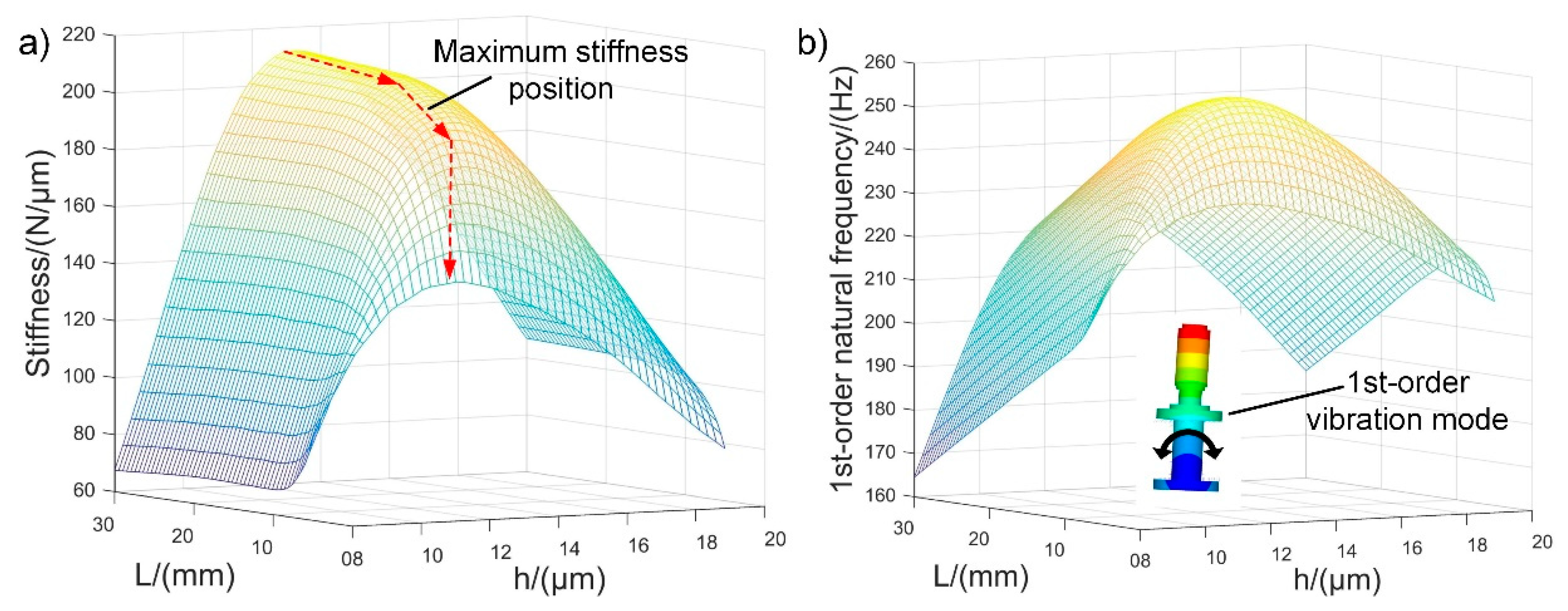
5.2. Optimal Design of the Structural Dimensions of the Aerostatic Spindle

Figure 7 presents the axial stiffness and the first-order natural frequency of the aerostatic spindle with varying thrust plate thickness and air film thickness considering the FSI effect. It can be derived from Figure 7a that with the increase of thrust plate thickness, the maximum stiffness increases sharply in the range of 5–15 mm and then increases slowly in the range of 15–30 mm. This phenomenon can be explained as follows. The structural rigidity of the thrust plate is directly related to its thickness. By increasing its thickness, its structural rigidity will be improved, and the deformation of the thrust plate will be smaller. When the thickness of the thrust plate is larger than 15 mm, the stiffness trends to steady gradually with the increase of the thrust plate. It is because that the structural rigidity of the thrust plate is high enough to resist the air film force. The stiffness is improved slightly by further increasing its thickness. Therefore, the range of 15–30 mm is recommended for the thrust plate thickness for higher stiffness.
However, the mass of the thrust plate is also directly related to its thickness. To increase the natural frequency, the designer generally hopes to reduce the mass of the rotating parts in the design stage. It means that the thickness of the thrust plate cannot be increased blindly. As shown in Figure 7b, with the increase of the thrust plate thickness, the first-order natural frequency first increases sharply and then declines quickly. A maximum region for the first-order natural frequency can be observed around the thrust plate thickness of 10–15 mm. This phenomenon can be explained as follows. According to the calculation result shown in Figure 7a, the stiffness first increases sharply and then trends to steady, while the mass increases linearly with the increase of the thrust plate thickness. Generally, the natural frequency is proportional to the stiffness and is inversely proportional to the mass. In the region where the stiffness increases sharply, the natural frequency increases with the increase of the thrust plate thickness. In the region where the stiffness increases slowly, the natural frequency decreases with the increase of the thrust plate thickness.
Considering the stiffness and natural frequency comprehensively, a thrust plate thickness of 20 mm is selected in this paper. Comparing with the initial design, the first-order natural frequency of the aerostatic spindle increases by 45.3%, from 167.4 Hz to 243.3 Hz.

6. Experimental Validation of the Calculation Result

To validate the above calculation result, the performance of the aerostatic spindle with optimized design parameters is measured in this section. Since the machining error and assembly error is unavoidable, the actual geometry size of the aerostatic bearings may deviate from the design value. The performance of aerostatic bearing is susceptible to orifice diameter and air film thickness. To minimize the errors introduced by the manufacturing and assembly process on the measurement results, the orifice diameter and air film thickness are first measured in this section.

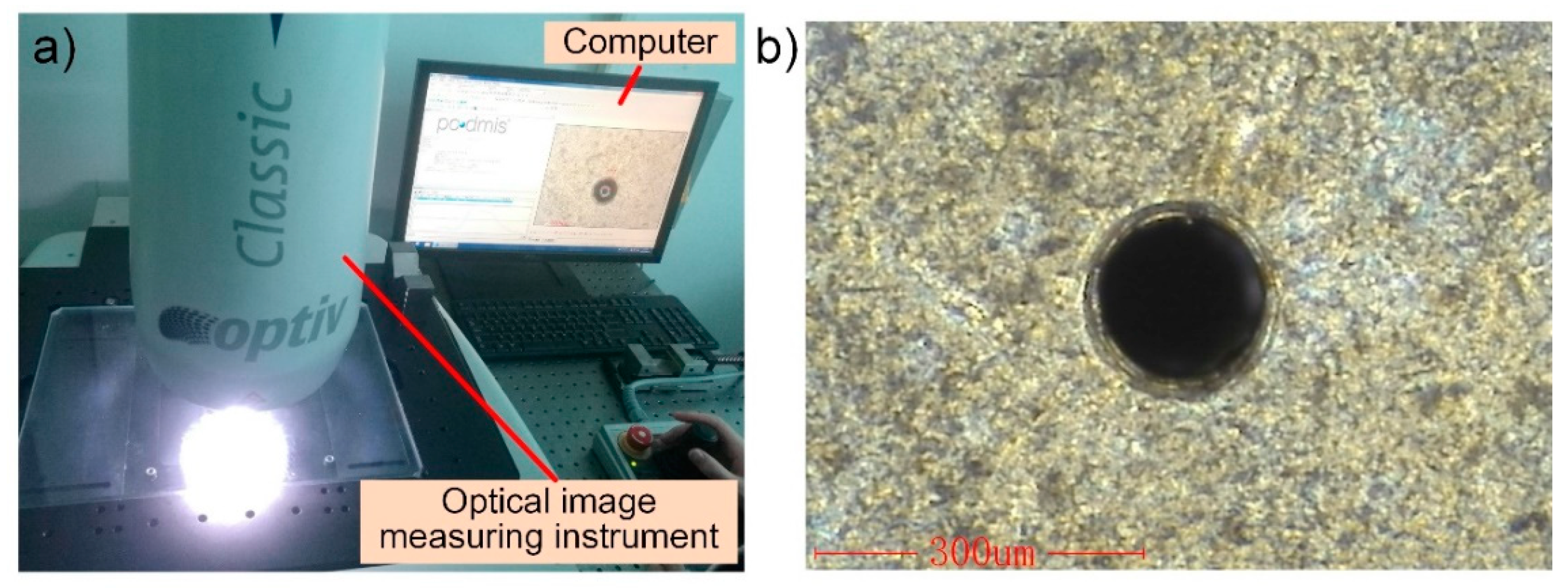
6.1. Measurement of Orifice Diameter

An optical image measuring instrument (Hexagon Optiv Classic 321GL tp) is employed in this research for orifice diameter measuring, as shown in Figure 8a. It has a CCD (Charge Coupled Device) image system to capture the image of the tiny object to be measured, which is capable to measure the contour and dimensions of various complex parts accurately and efficiently. Figure 8b presents a tested image of the orifice. As can be seen from the figure, the round outline of the orifice is clear, and no obvious burr can be observed. These orifices were acquired by micro-drilling machining. The image of the orifice indicates that excellent shape accuracy can be acquired by micro-drilling machining.
Table 2 lists the tested data of eight orifices. It shows that the actual diameter of the orifice diameter has a good consistency. The nominal size of the orifice diameter is 0.15 mm, and all the measured orifice diameter is around 0.15 mm with a dimension deviation less than ±5 μm, which indicates that the orifices have high dimensional accuracy.

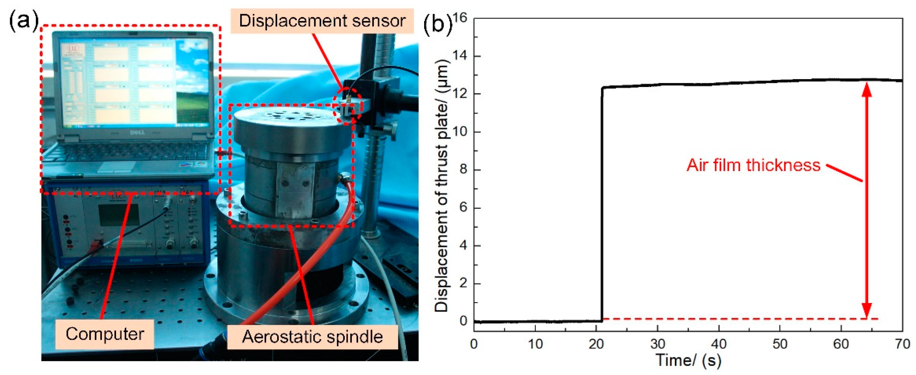
6.2. Measurement of Air Film Thickness

Generally, to ensure the static performance of the aerostatic bearing and the motion accuracy of a spindle, a serial of stringent machining accuracy requirements (including flatness, parallelism, and perpendicularity, etc.) are proposed for each part of the spindle system (the shaft, sleeve, and thrust plates). Nevertheless, the real air film thickness may deviate from the design value due to unavoidable machining errors and assembly errors.
Figure 9a presents the experimental setup for air film thickness measuring. By measuring the displacement of the thrust plate under the condition of the air supply valve closing and opening, the actual air film thickness can be acquired. A capacitive displacement sensor (Micro-Epsilon capaNCDT6500) with a resolution of 1 nm and a measurement range of 50 μm is employed in this research to record the displacement of the thrust plate. The experimental setup is mounted on a vibration isolation worktable to avoid the impact of external vibration.
Figure 9b shows the displacement curve of the thrust plate before and after the opening of the air supply valve. It can be seen that the thrust plate moves upward due to the support of pressurized air film. The above measuring process is implemented at eight points. These points are equally spaced along the circumferential direction of the thrust plate, and the tested data is detailed in Table 3. It can be inferred that the measured average air film thickness is about 12.84 μm, which is slightly less than the design value of 13 μm. It may result from the machining error of the shaft, sleeve, and thrust plate.

6.3. The Axial Stiffness Test of the Aerostatic Spindle

To verify the calculation result, the axial stiffness of the spindle with different thrust plate thicknesses is tested in this section. The stiffness test is conducted by applying different loads along the axial direction of the spindle and measuring the axial displacement of the spindle by a displacement sensor. The experimental apparatus mainly consists of a computer, a displacement sensor, and an aerostatic spindle, which is shown in Figure 10. The displacement of the thrust plate can be acquired by the displacement sensor with varying axial loading.
The experimental result is compared with the simulation result, as shown in Figure 11. It can be seen that the experimental curve and the simulation curve show the same trend. According to the test date, the axial stiffness of the spindle with the thrust plate thickness of 10 mm is 176.2 N/μm, which is much lower than the ideal stiffness of 209.6 N/μm. It proves that the stiffness will be declined due to structural deformation. By increasing the thrust plate thickness to 20 mm, the stiffness increases to 201.8 N/μm. It indicates that the structural rigidity of the thrust plate can be improved by increasing its thickness. With further increase of the thrust plate thickness to 30 mm, the axial stiffness of the spindle increases slightly to 204.2 N/μm. It means that the stiffness is close to the ideal stiffness with the further increase of the thrust plate thickness. The experimental result validates the accuracy of the FSI model.

7. Conclusions

This paper proposes a two-round optimization design method for aerostatic spindles considering the FSI effect. The optimal design of an aerostatic spindle is implemented as a case study to detail the design process of the proposed approach. A set of optimal design parameters are acquired, and experiments are implemented to verify the simulation results. The main conclusions are drawn as follows:
1. A two-round optimization design method is proposed to facilitate the design of the aerostatic spindle with consideration of the FSI effect, and an aerostatic spindle is optimized as a case study that validates the effectiveness of the proposed design method;
2. In the first-round design stage of the two-round optimization design method, a set of optimized design parameters of the aerostatic thrust bearing is acquired by analyzing the performance of the aerostatic thrust bearing with varying geometrical parameters of the restrictor. Compared with the initial design, the LCC is improved by 28.3%, the stiffness is improved by 44.2%, and the VFR is reduced by 27.2%;
3. In the second-round design stage of the two-round optimization design method, a recommended range for the design of thrust plate thickness is acquired by calculating the stiffness and natural frequency of the spindle with different thrust plate thicknesses. Compared with the initial design, the first-order natural frequency of the aerostatic spindle increases by 45.3%;
4. Experiments are conducted, and the experimental results agree well with the simulation results, which verifies the accuracy of simulation results.

Author Contributions

Conceptualization, Q.G.; methodology, L.L.; software, Q.G. and S.G.; validation, M.Z. and F.Z.; formal analysis, Q.G. and S.G.; investigation, Q.G. and S.G.; data curation, M.Z.; writing—original draft preparation, Q.G.; writing—review and editing, L.L.; visualization, Q.G.; funding acquisition, Q.G. and S.G. All authors have read and agreed to the published version of the manuscript.

Funding

This research was funded by the Heilongjiang Postdoctoral Foundation, grant number LBH-Z19149, the Leading Wild Goose Program Scientific Research Project of Harbin Institute of Technology, grant number XNAUEA5640202220-07, the National Natural Science Foundation of China, grant number 51705501, and the State Key Laboratory of Mechanical Transmissions in Chongqing University, grant number SKLMT-KFKT-201801.

Institutional Review Board Statement

Not applicable.

Informed Consent Statement

Not applicable.

Data Availability Statement

The data presented in this study are available on reasonable request from the corresponding author.

Conflicts of Interest

The authors declare no conflict of interest.

References

  1. Gao, Q.; Chen, W.; Lu, L.; Huo, D.; Cheng, K. Aerostatic bearings design and analysis with the application to precision engineering: State-of-the-art and future perspectives. Tribol. Int. 2019, 135, 1–17. [Google Scholar] [CrossRef]
  2. Chen, Y.; Chiu, C.; Cheng, Y. Influences of operational conditions and geometric parameters on the stiffness of aerostatic journal bearings. Precis. Eng. 2010, 34, 722–734. [Google Scholar] [CrossRef]
  3. Chen, X.; He, X. The effect of the recess shape on performance analysis of the gas-lubricated bearing in optical lithography. Tribol. Int. 2006, 39, 1336–1341. [Google Scholar] [CrossRef]
  4. Li, Y.; Ding, H. Influences of the geometrical parameters of aerostatic thrust bearing with pocketed orifice -type restrictor on its performance. Tribol. Int. 2007, 40, 1120–1126. [Google Scholar] [CrossRef]
  5. Belforte, G.; Colombo, F.; Raparelli, T.; Trivella, A.; Viktorov, V. Comparison between Grooved and Plane Aerostatic Thrust Bearings: Static Performance. Meccanica 2011, 46, 547–555. [Google Scholar] [CrossRef] [Green Version]
  6. Du, J.; Zhang, G.; Liu, T.; Suet, T. Improvement on load performance of externally pressurized gas journal bearings by opening pressure-equalizing grooves. Tribol. Int. 2014, 73, 156–166. [Google Scholar] [CrossRef]
  7. Hirani, H.; Suh, N.P. Journal bearing design using multiobjective genetic algorithm and axiomatic design approaches. Tribol. Int. 2005, 38, 481–491. [Google Scholar] [CrossRef]
  8. Wang, N.; Tsai, C.M.; Cha, K.C. Optimum design of externally pressurized air bearing using Cluster OpenMP. Tribol. Int. 2009, 42, 1180–1186. [Google Scholar] [CrossRef]
  9. Wang, N.; Cha, K.C. Multi-objective optimization of air bearings using hypercube-dividing method. Tribol. Int. 2010, 43, 1631–1638. [Google Scholar] [CrossRef]
  10. Wang, N.; Chang, Y.Z. Application of the Genetic Algorithm to the Multi-Objective Optimization of Air Bearings. Tribol. Lett. 2004, 17, 119–128. [Google Scholar] [CrossRef]
  11. Federico, C.; Marcello, C. Multi-objective optimization of a rectangular air bearing by means of genetic algorithms. J. Mech. Eng. Autom. 2012, 2, 355–364. [Google Scholar]
  12. Colombo, F.; Della Santa, F.; Pieraccini, S. Multi-Objective Optimisation of an Aerostatic Pad: Design of Position, Number and Diameter of the Supply Holes. J. Mech. 2020, 36, 347–360. [Google Scholar] [CrossRef]
  13. Bhat, N.; Barrans, S.M. Design and test of a Pareto optimal flat pad aerostatic bearing. Tribol. Int. 2008, 41, 181–188. [Google Scholar] [CrossRef]
  14. Luo, X.; Han, B.; Chen, X.; Li, X.; Jiang, W. Multi-physics modeling of tunable aerostatic bearing with air gap shape compensation. Tribol. Int. 2021, 153, 106587. [Google Scholar] [CrossRef]
  15. Gao, Q.; Lu, L.; Zhang, R.; Song, L.; Huo, D.; Wang, G. Investigation on the thermal behavior of an aerostatic spindle system considering multi-physics coupling effect. Int. J. Adv. Manuf. Technol. 2019, 102, 3813–3823. [Google Scholar] [CrossRef]
  16. Lu, L.; Chen, W.; Yu, N.; Wang, Z.; Chen, G. Aerostatic thrust bearing performances analysis considering the fluid-structure coupling effect. Proc. IMechE. Part J J. Eng. Tribol. 2016, 230, 1588–1596. [Google Scholar] [CrossRef]
  17. Lu, L.; Gao, Q.; Chen, W.; Liu, L.; Wang, G. Investigation on the fluid–structure interaction effect of an aerostatic spindle and the influence of structural dimensions on its performance. Proc. IMechE. Part J J. Eng. Tribol. 2017, 231, 1434–1440. [Google Scholar] [CrossRef]
  18. Gao, Q.; Lu, L.; Chen, W.; Liu, L.; Wang, G. A novel modeling method to investigate the performance of aerostatic spindle considering the fluid-structure interaction. Tribol. Int. 2017, 115, 461–469. [Google Scholar] [CrossRef]
  19. Powell, J.W. Design of Aerostatic Bearings; Machinery Pub. Co: Brighton, UK, 1970; pp. 89–99. [Google Scholar]
  20. Liu, T.; Liu, Y.; Chen, S. Aerostatic Lubrication; Harbin Institute of Technology Press: Harbin, China, 1990; pp. 51–98. [Google Scholar]
  21. Wang, Y. Gas Lubrication Theory and Gas Bearing Design; China Machine Press: Beijing, China, 1999; pp. 144–204. [Google Scholar]
  22. Gao, Q.; Zhao, H.; Lu, L.; Chen, W.; Zhang, F. Investigation on the formation mechanism and controlling method of machined surface topography of ultra-precision flycutting machining. Int. J. Adv. Manuf. Technol. 2020, 106, 3311–3320. [Google Scholar] [CrossRef]
  23. Gao, Q.; Qi, L.; Gao, S.; Lu, L.; Song, L.; Zhang, F. A FEM based modeling method for analyzing the static performance of aerostatic thrust bearings considering the fluid-structure interaction. Tribol. Int. 2021, 156, 106849. [Google Scholar] [CrossRef]
  24. Xu, R. Finite Element Method in Structural Analyses and MATLAB Programming; China Communication Press: Beijing, China, 2006; pp. 161–188. [Google Scholar]
Figure 1. A two-round optimization design method for aerostatic spindles considering the fluid–structure interaction (FSI).
Applsci 11 03017 g001
Figure 2. The configuration of an aerostatic spindle and the design parameters of its thrust bearing. (a) The configuration of the aerostatic spindle and (b) the design parameters of the thrust bearing.
Applsci 11 03017 g002
Figure 3. The finite element method (FEM) model of the air thrust bearing.
Applsci 11 03017 g003
Figure 4. The performance curves of aerostatic thrust bearing with varying d and h.
Applsci 11 03017 g004
Figure 5. The performance curves of aerostatic thrust bearing with varying orifice number n.
Applsci 11 03017 g005
Figure 6. The FSI model of the aerostatic thrust bearing. (a) The FEM model of aerostatic thrust bearing; (b) the pressure distribution of air film; (c) the pressure load applied on thrust plate; (d) the FEM model of thrust plate; and (e) the structure deformation of the thrust plate.
Applsci 11 03017 g006
Figure 7. The performance of aerostatic spindle with varying thrust plate thickness L and air film thickness h. (a) The axial stiffness of the spindle with different thrust plate thickness L and air film thickness h and (b) the first-order natural frequency of the aerostatic spindle with varying thrust plate thickness L and air film thickness h.
Applsci 11 03017 g007
Figure 8. Experimental setup for orifice diameter measuring. (a) The Experimental apparatus for orifice diameter test and (b) the tested image of an orifice.
Applsci 11 03017 g008
Figure 9. Experimental setup for air film thickness measuring and test result. (a) The Experimental setup for air film thickness measuring and (b) a test result of the air film thickness test.
Applsci 11 03017 g009
Figure 10. Experimental apparatus for the stiffness test.
Applsci 11 03017 g010
Figure 11. Comparison between the simulation result and experimental result.
Applsci 11 03017 g011
Table 1. The design parameters of the aerostatic thrust bearing.
D1 (mm)D2 (mm)D3 (mm)d (mm)h (μm)d1 (mm)h1 (mm)nL (mm)
6088.31300.21660.05630
Table 2. Experimental result of the orifice diameter.
Orifice Number12345678
Orifice diameter (mm)0.1480.1470.1540.1480.1530.1520.1510.151
Table 3. Measuring result of the air film thickness.
Test Point12345678
Air film thickness (μm)12.8612.7212.8912.7812.9312.8412.8612.84
Publisher’s Note: MDPI stays neutral with regard to jurisdictional claims in published maps and institutional affiliations.

