Article

Multi-Criteria Parametric Verifications for Stability Diagnosis of Rammed-Earth Historic Urban Ramparts Working as Retaining Walls

by
Álvaro R. Serrano-Chacón
1,
Emilio J. Mascort-Albea
1,*,
Jacinto Canivell
2,
Rocío Romero-Hernández
1 and
Antonio Jaramillo-Morilla
1
1
Departamento de Estructuras de Edificación e Ingeniería del Terreno, Escuela Técnica Superior de Arquitectura, Instituto Universitario de Arquitectura y Ciencias de la Construcción, Universidad de Sevilla, 41012 Seville, Spain
2
Departamento de Construcciones Arquitectónicas II, Escuela Técnica Superior de Ingeniería de la Edificación, Instituto Universitario de Arquitectura y Ciencias de la Construcción, Universidad de Sevilla, 41013 Seville, Spain
*
Author to whom correspondence should be addressed.
Appl. Sci. 2021, 11(6), 2744; https://doi.org/10.3390/app11062744
Submission received: 2 March 2021 / Revised: 12 March 2021 / Accepted: 15 March 2021 / Published: 18 March 2021

Abstract

:

Featured Application

Justifying the novelty of the approach, this proposal considers the programming of parametric calculation tools for the evaluation of the stability of historical ramparts built with earth, which work as retaining walls. Given the amount of examples located in urban contexts, the applica-tion of these methods to the medieval ramparts of Seville (Spain) is highly representative and replicable.

Abstract

Institutions such as ICOFORT (International committee on fortifications and military heritage) encourages the development of diagnosis strategies for the conservation and maintenance of historic earthen walls as highly necessary. Thus, it is important to be aware of the conditions in urban contexts, where the deterioration can be more aggressive and the risk of damage increases. Despite this, there are many strategies of constructive diagnosis for these kinds of monuments, but not many of them are concerned with the structural assessment of situations in which the ramparts work as a retaining wall in an unforeseen way. The medieval ramparts of Seville (Spain) are shown as a completely representative case study of the above-mentioned situation. In the research sector, the monument resists the lateral earth pressure developed by the new difference in height at both sides of the wall. Based on the limited states principle and on different international codes formulation, a tool was programmed to carry out automatic calculations to verify the case study’s overall stability conditions using standard sections. The obtained results were based on the overturning, bearing, and sliding overdesign factors (ODF) and determined a stable situation that could be at risk because of changes in the surrounding such as, excavations or the movements of the ground water table, or seismic events. Thus, the need and usefulness of strategies and control instruments that should be integrated into heritage intervention projects have been proved.

1. Introduction

The importance of historical military architecture is particularly significant in the case of monuments built on earth, and especially abundant when dealing with medieval fortresses in the Iberian Peninsula [1]. The ecological value of the material, the traditional approach of the construction techniques employed, and their territorial scale make this type of heritage of special interest for the development of research and conservation initiatives. International institutions such as ICOFORT (ICOMOS International Scientific Committee on Fortifications and Military Heritage) highlight the main risks threatening this architectural category. A specific approach to earthen fortifications is in need due to their specific problems and values, which are completely different to other kinds of heritage [2].
In the case of the urban fortified enclosures, and to the normal risks, we must add the pressure of urban development, which throughout history has altered or destroyed a large part of these structures. The emerging sectors of these fortifications nowadays often receive regular maintenance, but also endure physical and mechanical conditions for which they were not designed. The most common transformations of their context derive from topographical operations and changes in the alignment of urban streets, as well as from the demolition and reconstruction of their surrounding buildings.
On many occasions, urban changes over the centuries mean that certain sectors of historic earthen walls end up working as retaining elements. This is due to the massiveness and proportions of the defensive ramparts. Nevertheless, this situation was not usually foreseen in the original design of the fortification walls and can lead to a significant physical deterioration of the monument and to situations of structural instability. Often walls in urban areas suffer changes of use, which requires drastic measures to be taken for their conservation as the new use can be incompatible with the original design. For instance, part of the rampart found in Granada [3], which was initially designed to protect the city from flooding of the Genil river ended being up part of a new building. The continuous changes in the initial conditions can damage the wall in the medium/short term. In most cases, as the walls are gravity type structures and are usually very stable, the damage does not compromise the structural stability, although it does lead to weathering and mass-loss processes. In these cases, there are different ways of solving the problem, which usually take into account, among other things, the restitution of the lost material not to compromise stability. In the restoration of several walls in the Generalife of the Alhambra in Granada, an innovative technique of soil projection was applied, in order to restore the lost part of the section because of the water seepage from the backfill [4]. In any case, stability verifications should be performed after any changes have been in use and also whenever the section of the wall is changed. The authors have found that this issue has been inadequately addressed in literature.
Despite the large number of studies that address the constructive degradation of military earthen architecture in urban contexts [5,6,7,8], no research has been found on the structural study of cases in which historic ramparts work as retaining elements. This is precisely the main novelty of the topic discussed and developed in this research. Therefore, quick testing tools that can be mathematically validated are in need.
However, some interesting experiences approach the assessment of fortified structures with compacted soil from different perspectives, especially in consolidated urban areas. The first approach to this problem is risk management and hazard assessment in these environments. To this end, Ladiana [5] proposes the use of satellite interferometry as a method to monitor real-time movement of these structures to predict certain behaviors that may pose a threat in the short term. Other authors have developed qualitative-quantitative methodologies to evaluate the displacements of historical retaining walls using numerical analysis [9]. With this approach, through a new algorithm, it is possible to select and design the most appropriate technical solutions for each case based on the types of displacements analyzed. Other approaches focus more on the analysis of the original materials themselves, using a set of physical-mechanical tests designed specifically for the wall, which allow the subsequent selection of the most compatible materials for restoration [10,11]. The proposal for the conservation of the Pingyao Wall (China) follows a similar approach. This structure, several meters thick, built with a large core of compacted soil and partially covered with brick, was threatened by collapses. The authors hence proposed a qualitative methodology for monitoring the damage and studying the materials to choose the most suitable restoration techniques, basically by restoring the mass of the affected wall [12]. In any case, these proposals have been designed to evaluate a type of threat or to analyze the current state of conservation materially. There are other proposals in the literature using a multi-criteria option to establish a more global assessment of the vulnerability of compacted earth structures. Fuzzy logic tools and parameterization were used in the section of the Great Wall of China (Qinghai Province) obtaining the risk of collapse of the earth structures [7,8]. However, none of the alternatives found in the literature specifically address the structural and mathematical analysis of compacted earthen walls, and neither the lateral earth pressure is considered.
Based on the limit states method, and the main standards of calculation currently in use, a safety verification tool for structural calculation purposes is proposed for the assessment of historic ramparts with lateral earth pressure. Thus, the main objective of this research is to develop, and validate, an automated calculation model, based on the current national and international regulation codes, useful to take decisions regarding the diagnostic and intervention. Likewise, an assessment of the case study will be addressed in order to check its structural stability and validate the model using safety factors. The following sections explain the mathematical basis of the tool and the indicators that will be used to establish the safety factors (Section 2), the operational development of the calculation tool (Section 3) and its application to a representative case study such as the Medieval Wall of Seville, located in Spain (Section 4). Finally, the results and their discussion are provided (Section 5), as well as the conclusions of the research (Section 6).

2. Structural Assessment. Limit States Calculation Methods, Design Situation, and Loads

The assessment of existing structures is intended to quantify their safety factor and, subsequently, determine whether conservation and reinforcement works are in order. Whatever structural analysis based on limit state calculation methods is conducted, there is a set of variables that must be considered, such as geometric data, material properties, and loads, among others [13]. Depending on whether the parameters are considered fixed values or random ones, two approaches for structural assessment can be distinguished: probabilistic and deterministic [14,15,16]. Most of the structural design codes are based on the second approach, where the limit state surface is the boundary between the safe and unsafe domains. It should be noted that addressing this problem strictly in terms of probability could be extremely complex [17] so that it is common practice to simplify the structural assessment by using partial factors. Therefore, the use of safety coefficients is a key indicator for the verification of the structural condition of the buildings analyzed in this research.
Mainly two limit states are proposed on structural and geotechnical assessment [18]: Ultimate Limit State (ULS), related to those situations that compromise people’s life, either caused by the partial or total collapse of the structure (e.g., loss of overall stability, bearing capacity, sliding or overturning failure); and Serviceability Limit State (SLS), related with user comfort or the appearance of the construction (e.g., excessive settlements, unacceptable vibrations). Basically, state limits aim at ensuring the safety, serviceability and durability of the construction. This paper mainly focuses on analysing ultimate limit states since the collapse of the structure could occur in these cases.
Based on previous research [19], the comparative study between the formulations provided by different international codes allows to obtain an appropriate mathematical basis for the verification of built structures. According to its representativeness and validity, the following documents have been selected for a comparative study as a basis for the developed tool. Due to a recent update in 2019, Basic Document Structural Safety of the Spanish Technical Building Code (CTE DB SE, v2019) [20], the 2019 version of Basic Document Structural Safety Foundations of the Spanish Technical Building Code (CTE DB SE-C, v2019) [21] and the 2009 version of Earthquake Resistant Construction Standard: General Part and Building (NCSE-02) [22], the Spanish regulation documents have been selected as remarkable samples from a national structural design code [23]. On the other hand, the last published versions of Eurocode constitute highly representative documents at the international level. For this study, there will be considered the following ones: EN 1991-1-4 Eurocode 1: Actions on Structures. Part 1–4: General Actions- Wind actions (EC1-4, v2010) [24], EN 1990-7-1 Eurocode 7: Geotechnical design—Part 1: General rules (EC7-1, v2005) [25] and EN 1998-8-5 November Eurocode 8: Design of structures for earthquake resistance—Part 5: Foundations, retaining structures, and geotechnical aspects (EC8-5, v2004) [26]. These documents set a long list of ultimate limit states, but only three of them are considered: overturning, sliding, and bearing failures. In simple terms, the first limit state is verification of static equilibrium (EQU Limit State) of the structure, which is considered as a rigid body, whereas the two others are verifications based on ground resistance (GEO Limit State). The main formulations for determining equilibrium states are discussed in the next sub-sections.

2.1. EQU Ultimate Limit States

According to EC7-1 and CTE DB SE-C, the verification of static equilibrium of the foundation is determined by Equation (1), where E s t b ; d is the design value of the effect of destabilizing actions, E s t b ; d is the design value of the effect of stabilizing actions and T d is the design value of any stabilizing shear resistance of the ground or structural elements. In accordance with EC7-1, expression to obtain the two first terms is given by Equation (2), which includes several parameters: F k is the characteristic value of an action, Ψ is the factor for converting the characteristic value to the representative value, γ F is the partial factor for an action, X k is the characteristic value of material property, γ M is the partial factor for a soil parameter and a d is the design value of geometrical data. As it can be seen in Equation (3), the expression given by the CTE DB SE-C to obtain these terms is quite similar, but adding a partial factor for the effect of actions ( γ E ).
E d s t ; d E s t b ; d + T d
E i ; d = E γ F Ψ · F k ; X k / γ M ; a d i
E i ; d = γ E E γ F Ψ · F k ; X k / γ M ; a d i

EQU Limit State: Overturning Resistance

The structure is considered as a rigid body for this limit state. This assumption implies that both soil and structure are considered non-deformable and, consequently, failure is not expected from them. Basically, verification of this limit state requires solving a static equilibrium problem according to Equation (1).

2.2. GEO Ultimate Limit States

Regarding sliding and bearing failures, the determining factor is the ground resistance. The verification of such limit states, both with EC7-1 and CTE DB SE-C, is given by Equation (4), where E d is the design effect of actions and R d is the corresponding design resistance.
E d R d
EC7-1 proposes Equation (5) for the calculation of E d and distinguishes three design approaches, each one of them with different values for actions (A), soil parameters (M) and resistances (R). According to National Annex, design approach 2 is used for these limit states in Spain, taking this set of partial factors: A1, M1, R2. The proposal of CTE DB SE-C for verification includes a partial factor for the effect of actions γ E as defined in Equation (6).
E d = E γ F Ψ · F k ; X k / γ M ; a d
E d = γ E E γ F Ψ · F k ; X k / γ M ; a d
To obtain the value of R d , both EC7-1 and CTE DB SE-C propose Equation (7), which includes the single resistance factor γ R as a novelty concerning the previously explained terms.
R d = R γ F Ψ · F k ; X k / γ M ; a d / γ R

2.2.1. GEO Limit State: Bearing Resistance

Table 1 contains the approaches of EC7-1 and CTE DB SE-C for the calculation of the design bearing resistance for drained conditions. As shown in Equations (8)–(35), the expressions are quite similar in both codes. In order to determine this resistance it is necessary to apply a set of correction coefficients: bearing capacity factors ( N values), the inclination of the base ( b values), the depth of the base ( d values), the shape of the footing ( s values), foundation on top of a slope ( t values) and the inclination of the loads ( i values).

2.2.2. GEO Limit State: Sliding Resistance

Determination of design sliding resistance for drained conditions according to EC7-1 is given by Equation (36), where V d is the design value of the effective vertical action, δ k is the friction angle, and γ R is the partial factor for resistance. In the absence of information, the value of the second parameter can be determined by means of Equation (37). The expression to quantify the design sliding resistance according to CTE DB SE-C is given by Equation (38), where N is equivalent to V d in Equation (36) and B is the width of the base of the wall. In this case, effective cohesion is included, but its value is reduced by a factor of 0.5. For verifications, the friction angle of shearing resistance is also reduced by a factor of 2/3.
R d =   V d   tg δ k / γ R
tg   δ k   0.8   tg   ϕ
R d =   N   tg   ϕ + c B / γ R

2.3. Design Situations

On one side, EC7-1 defines three design situations: persistent (or transient), accidental and seismic, being the design effect of actions given by Equations (39)–(41), respectively. Essentially, these expressions are an expanded version of those seen previously, since the characteristic value of action expressed as F k has been replaced by the specific type of action, namely: Permanent (G), Variable (Q), or Accidental (A). Although prestressing actions (P) are contained in the expressions, there are no such actions in the case study. Partial factors are particularized for each type of action by using the corresponding sub-index.
j 1 γ G , j G K , j + γ P P + γ Q , 1 Q K , 1 + i > 1 γ Q , i ψ 0 , i Q K , i
j 1 G K , j + P + A d + ψ 1 , 1 Q K , 1 + i > 1 ψ 2 , i Q K , i
j 1 G K , j + P + A d + i 1 ψ 2 , i Q K , i
On the other side, two design situations are mentioned in the CTE DB SE: persistent (or transient) and extraordinary. The design effect of actions for the first scenario coincides with Equation (39). The second scenario includes the consideration of accidental actions on the structure. In case of seismic action, the design effect of the actions is computed according to Equation (41). Otherwise, Equation (40) is applied.
Considering all limit states and design situations presented before, the number of cases for verifications is significant. Values for partial factors on actions or their effects are summarized in Table 2, whereas partial factor for resistances are shown in Table 3. As for partial factors for soil parameters (such as the angle of shearing resistance, effective cohesion or the weight density, among others), they take a value of 1 for GEO limit states, according to the design approach appointed for Spain. However, a partial factor of 1.25 is applied to the angle of shearing resistance and the effective cohesion for EQU limit state.

2.4. Loads

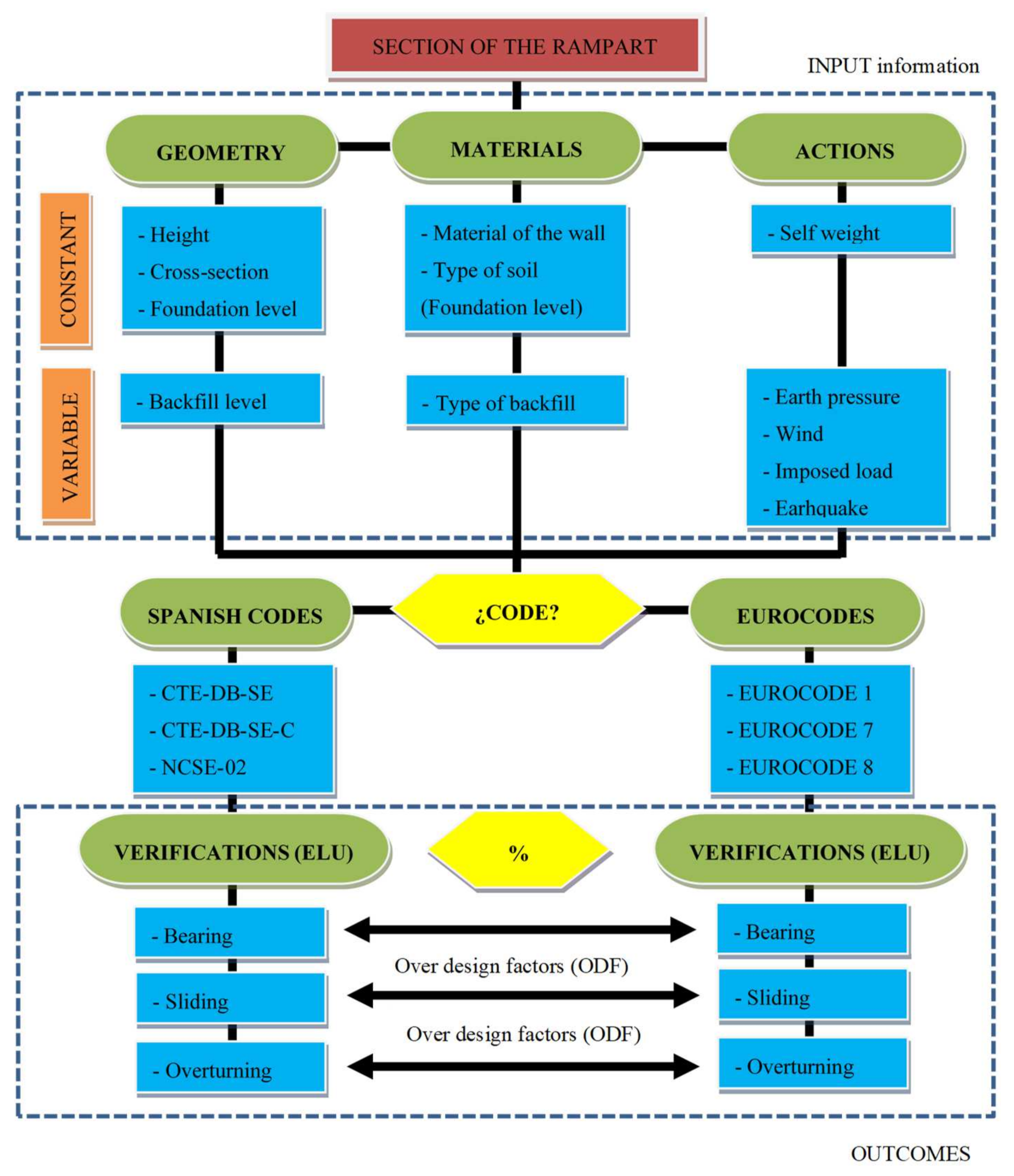
For geotechnical verifications, several actions have been considered, namely: self-weight of the structure, the lateral earth pressure from the backfills, a uniform surcharge loading over the backfill, the wind, and the effect of a possible seismic event. The weight of the structure is directly determined by multiplying the density of the wall by its cross-sectional area. However, the magnitude of the rest of the forces acting on the structure is not straightforward to estimate and will be discussed in detail hereafter.

2.4.1. Lateral Earth Pressure

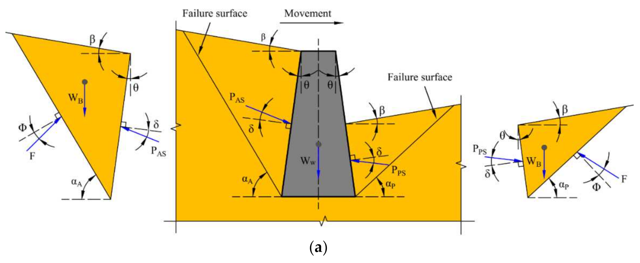
Checking the lateral pressure from the backfill, two methods have been considered among the possibilities currently available [27]: the Coulomb method (Figure 1a), in case of static conditions, and the Mononobe-Okabe method (Figure 1b) for dynamic conditions from seismic events.
  • Static case: Coulomb Method
Because friction between the wall and the soil is considered, Coulomb’s theory is applied in order to determine the resultant force ( P A S ) in case of active earth pressure (Figure 1a). This method assumes that the failure surface is two-dimensional and passes through the heel of the wall, whose inclination to the horizontal plane ( α A ) is unknown. This failure plane in conjunction with wall surface closer to the backfill defines a wedge of soil, which can slide over these two planes [28]. For this particular case of active earth pressure, this wedge moves away from the backfill and downward. By posing the equilibrium of this wedge as a rigid body in terms of the angle ( α A ) and solving an optimization problem, a maximum value for P A S is obtained. The force obtained thereby is located at one-third of the height of backfill from the bottom and acts at an angle ( δ ) with the normal to the back of the wall, which ranges from 1/3 to 2/3 times the soil friction angle (ϕ ). The magnitude of this force is obtained by applying Equation (42), where K A S is defined by Equation (43).
P A S = 1 2   γ   H 2   K A S
K A S = cos 2 ϕ d θ cos 2   θ cos θ + δ d 1 + sen ϕ d + δ d sen ϕ d β cos δ d + θ cos β θ     2
ϕ d = tan 1 tan ϕ ϒ ϕ
δ d = tan 1 tan δ ϒ ϕ
In the case of the wall supporting a uniform surcharge (q), the resultant force ( P A S ) must also include the lateral earth pressure of the soil skeleton as a result of the imposed load. For this scenario, it is necessary to define a new value of unit weight for the wedge γ * to take the surcharge into account. Its magnitude can be obtained according to Equation (46):
γ * = γ 1 + 2 q cos θ γ H cos β θ
By using Coulomb’s theory it is also possible to determine the magnitude of the resultant force ( P P S ) in case of passive earth pressure (Figure 1a). In this case, the wedge defined by the horizontal plane ( α P ) moves towards the backfill and upward. As previously, this force is located at one-third of the height of the backfill from the bottom and acts at an angle ( δ ) with the normal to the back of the wall, taking a zero value. The magnitude of the resultant force is now obtained by applying Equation (47), where K P S is defined by Equation (48).
P P S = 1 2   γ   H 2   K P S
K P S = cos 2 ϕ d + θ cos 2   θ cos δ d θ 1 sen ϕ d + δ d sen ϕ d + β cos δ d θ cos β θ     2
  • Dynamic case: Mononobe Okabe Method
An estimation of the resultant force during earthquakes is performed using the Mononobe-Okabe method [29,30,31], which is considered to be an extension of the above-mentioned Coulomb’s theory. Seismic loads are applied to the soil wedge by using a pseudo-static method, so that horizontal and vertical inertia forces are introduced into the model using coefficients (Figure 1b). The horizontal component of the inertia force is oriented away from the backfill, in order to obtain a greater value of the resultant force ( P A D ) in case of active earth pressure. According to the simplified procedure posed by Seed and Whitman in 1970 [32], this dynamic force can be decomposed into the sum of the static case and a force increment, as shown in Equation (49). The seismic increment component is determined by using Equation (50), where K A D is defined by Equation (51).
P A D = P A S + Δ P A D
Δ P A D = 1 2   γ   H 2 K A D K A S
K A D = 1 k v cos 2 ϕ d ψ θ cos ψ   cos 2   θ cos ψ + θ + δ d 1 + sen ϕ d + δ d sen ϕ d ψ β cos δ d + ψ + θ   cos β θ   2
It should be considered that high values for the inclination angle of the backfill surface from the horizontal line β may result in a negative value for the square root term in Equation (51). Consequently, parameter K A D would be expressed in terms of complex values. In this situation, the term in brackets of this expression is forced to be 1 to work with real numbers.
By applying this method, the total magnitude of seismic active force is determined. However, even though some research has been carried out, its point of application is not straightforward. EC8-5 states that this force increment is located at mid-height of the backfill, whereas NCSE-02 sets its location at 2/3 of the height from the foundation plane. Static and dynamic components are orientated in the same direction and act at an angle ( δ ) with the normal to the back of the wall.
Similarly to the procedure described for the dynamic active case, Towhata and Islam in 1987 [33] developed a simplified procedure to determine the resultant force ( P P D ) in case of passive earth pressure. Among the main hypotheses considered, the following should be highlighted: vertical wall ( θ = 0 ), granular horizontal backfill ( β = 0 ), and no friction between the soil and the retaining wall ( δ = 0 ). The seismic increment component is determined using Equation (53), where K P D is defined by Equation (54). Static and dynamic components are orientated in the same direction and act at an angle ( δ ) with the normal to the back of the wall. No information about the point of application of force increment is considered in the codes, so it is assumed to be the same considerations as in the active case.
P P D = P P S Δ P P D
Δ P P D = 1 2 γ H 2 K P S K P D
K P D = 1 k v cos 2 ϕ d ψ + θ cos ψ cos 2 θ cos ψ θ + δ d 1 sen ϕ d + δ d sen ϕ d ψ + β cos δ d + ψ θ   cos β θ   2
Comparing Equations (43), (48), (51), and (54) it is obvious that a new parameter ψ is introduced, whose value is determined by employing Equation (55), where k h and k v are the horizontal and vertical seismic coefficients, respectively.
tan ψ = k h 1 k v
The horizontal coefficient is obtained by Equation (56) and it depends on several factors, namely: α , the ratio of the design ground acceleration on type A ground a g to the acceleration of gravity; S , the soil factor; and r , which is a factor that accounts for the type of retaining structure (taken from Table 7.1 of EC8-5). Conversely, the vertical coefficient is calculated more easily by multiplying the horizontal coefficient previously calculated by a constant according to Equation (57a,b).
k h = α S r
k v = ± 0.5 k h if a v g / a g   is   larger   than   0.6
k v = ± 0.33 k h otherwise
According to Equation (58), a g is calculated from the reference peak ground acceleration on type A ground a g R and the importance factor γ I .
a g = γ I a g R
CTE-DB-SE estimates that seismic forces acting on the structure must be taken into account according to NCSE-02, which refers to the Mononobe-Okabe method to account for the seismic action on the retaining wall. It should be noted that its expressions are following EC8-5 but with a slight difference in the value of the horizontal seismic coefficient, which is calculated through Equation (59).
k h = a c g
According to NCSE-02, design ground acceleration is obtained by Equation (60), where a b is the basic seismic acceleration, ρ is a dimensionless risk coefficient (1.0 or 1.3 depending on the importance of the structure) and S is the soil amplification coefficient. The latter is obtained using Equation (61a–c), depending on the product of the two previous coefficients. These expressions include a new parameter C, called soil coefficient and its value ranges from 1.0 to 2.0.
a c = S ρ a b
S = C 1.25 for ρ a b 0.1 g
S = C 1.25 + 3.33 ρ a b g 0.1 1 C 1.25 for 0.1 g ρ a b 0.4 g
S = 1.0 for 0.4 g ρ a b

2.4.2. Wind Action

Agreeing with the considerations of Rodriguez-León and Sanchez-Sánchez [19], EC1 and CTE-DB-SE provide remarkably similar formulation approaches to determine wind action over structural elements. EC1 states that the wind pressure acting on an external surface w E can be obtained from the Equation (62), where q b is the basic velocity pressure, c e z e is the exposure factor at the reference height and c pe is the pressure coefficient, whose value is based on the shape and geometry of the structure. Likewise, CTE-DB-SE calculates the wind pressure on an external surface ( q e ) by Equation (64) using very similar factors as EC1, namely: the basic velocity pressure ( q b ), the exposure factor ( c e ) and the pressure coefficient c p .
w E = q b · c e z e · c p e
q e = q b · c e · c p
According to the first factor of Equations (62) and (63), the basic velocity pressure ( q b ), is obtained by Equation (64), where v b is the basic wind velocity and c p r o b is the probability factor, given by Equations (65) and (66), respectively; and ρ is the air density (recommended value 1.25 kg/m3). Additionally, c d i r is the directional factor, c s e a s o n is the season factor (set equal to 1 in both cases following recommendations) and v b , 0 is the fundamental value of the basic wind velocity, whose value is specified in each National Annex. Additionally, K is the shape parameter depending on the coefficient of variation of the extreme-value distribution, n is a constant (their recommended values are 0.2 and 0.5, respectively) and p is the annual probability of wind velocity exceeding the fundamental value of basic wind velocity (expressed as the inverse of return period).
q b = 1 2 · ρ · v b · c p r o b 2
v b = c d i r · c s e a s o n · v b , 0
c p r o b = 1 K · ln ln 1 p 1 K · ln ln 0.98 n
The exposure factor at the reference height c e z e is obtained according to Equation (67). It should be noted that the numerator is known as the peak velocity pressure at the reference height q p z e whereas the denominator is the basic velocity pressure introduced above. The terms I v z e and v m z e are the turbulence intensity and the mean wind velocity at the reference height z e respectively, determined by Equation (68a,b) and (69) as appropriate. Additionally, k 1 is the turbulence factor and c 0 z e is the orography factor (their recommended values are (1); and z o is the roughness length. Finally, a new parameter is introduced in this last expression, called the roughness factor c r z e . Its value is obtained using Equation (70a,b), depending on the height reference, taking z m a x at a value of 200 m.
c e z e = 1 + 7 · I v z e · 1 2 · ρ · v m 2 z e 1 2 · ρ · v b · c p r o b 2
I v z e = k 1 c 0 z e · ln z e z o for z m i n z e z m a x
I v z e = I v z m i n for z e z m i n
v m z e = c r z e · c 0 z e · ( v b · C p r o p )
c r z e = 0.19 · z 0 0.05 0.07 · ln z e z 0 for z m i n z e z m a x
c r z e = c r z m i n for z e z m i n
According to Equation (64), CTE-DB-SE proposes that basic velocity pressure ( q b ) is calculated by Equation (71), and the exposure factor c e is obtained according to Equations (72) and (73), where k , L , Z are parameters selected in accordance with the surroundings of the structure (Table D.2 of CTE).
q b = 1 2 · δ · v b · c p r o b 2
c e z = F · F + 7 · k
F = k · ln max z , Z / L

3. Calculation Tool Features

Basically, fortified enclosures, such as the Macarena Wall, consist of a set of towers and rectangular cross-section walls that span long distances between them. On many occasions, the urban development of cities has led to the construction of streets or even buildings attached to these historic structures. As a result, there is a significant variation in the level of the backfill on both sides of the rampart. In other words, the fortified enclosure ends up working as a retaining wall, clearly distinct from its primary military function. This new situation could cause geotechnical instability of the foundation and, thus, the collapse of this valuable heritage.
In order to check the safety of the ramparts under these new circumstances, an Excel spreadsheet has been developed to quickly run geotechnical verifications on these kinds of buildings. A quick structural safety assessment helps to prevent severe damage or even collapse. This analytic tool is designed under the assumption that the walls of the rampart are homogeneous rigid solids and infinitely long, as the separation between towers is usually lengthy. On the safety side, the contribution to stability resulting from the wall-tower connection has not been considered. Thus, the way to analyze the stability of the fortified enclosure is to consider each stretch of wall in isolation. It is common for these ancient structures to have a slight difference in height between the ends, both for the wall and the backfill. It is advisable to consider an average value for these parameters.
In the process of geotechnical verification of one of these retaining walls, there are some parameters that remain constant. This is the case of the dimensions of the wall, its foundation level, or the type of foundation soil. Precisely, the latter determines the bearing capacity and the resistance to sliding. However, as a result of human action, the type of backfill or its height may change over time. The resulting geometry and soil properties determine the earth pressures on both sides of the retaining wall. The wind action together with the imposed loads on the pavement in case of streets attached to ramparts have been considered. Due to the high seismic vulnerability of this type of buildings, this action has also been included in the geotechnical verifications. The change in the magnitude of these actions is withstood by the weight of the retaining wall, as it is quite a massive structure. Once the case study is well defined, the checks corresponding to the abovementioned ultimate limit states are carried out. In this way, the level of security according to CTE DB SE and the Eurocode 7 can be compared. The whole process is shown in Figure 2.

4. Case Study Definition

The case study for the application of the developed tool is the medieval Wall of Seville and, more specifically, its preserved part located in the urban sector of the Macarena neighborhood. The design situations and the stretch selected for carrying out the geotechnical verifications are explained below.

4.1. Design Situations and Loads

Even though Seville is not a high seismic activity in a worldwide context, it has been struck by several earthquakes throughout history. Among them, the 1755 Lisbon earthquake can be highlighted, leaving about 10 people dead and causing severe damage to many ancient buildings such as the Salvador Church and the Cathedral [34]. For this reason, two design situations have been considered for geotechnical verifications of the case study: (i) persistent situation, which corresponds to the usual condition of use; and (ii) seismic situation, which includes the exceptional condition caused by an earthquake. For each design situation, safety against overturning, sliding, and bearing is evaluated independently by using the CTE and the Eurocode expressions.
The first situation (i) considers the weight of the wall itself, the static lateral earth pressure of the backfill on both sides of the wall, a uniform surcharge of 5 kN/m2 on the street and the action of the wind. For all the resistance verifications, two leading variable actions have been considered, namely the uniform imposed load on pavement and the wind, acting in both cases on the side of the wall next to the street. To compute the latter, a return period of 50 years has been considered. For the city of Seville, the fundamental value of the basic wind velocity is 26 m/s. As the case study is located in an urban area, terrain category IV is selected in accordance with CTE-DB-SE, k , L   , and Z parameters being equal to 0.22, 0.3, and 5.0 m respectively. In the case of Eurocode 1, terrain category III is chosen due to the low height of nearby buildings. Thus, z 0 is equal to 0.3 m whereas z m i n takes a value of 5 m. It should be noted that the effect of wind for free-standing walls is not included in the CTE-DB-SE, taking pressure coefficient from Eurocode 1. Although the wall is divided into different zones, verifications is carried out for the one with the greater pressure coefficient. In a certain way, the large towers attached to the walls represent corners and, consequently, a value of 2.1 for the pressure coefficient has been taken.
In the second situation (ii) the inertia forces on the wall and the dynamic lateral earth pressure derived from the backfills and the imposed load are considered, but the action of the wind is neglected as its quasi-permanent value (ψ2) equals to zero. Horizontal seismic action is directed towards the backfill on the street side. As for vertical seismic action, it has been considered to act upward and downward. According to NCSE-02, the basic seismic acceleration ( a b ) is set equal to 0.07 g for Seville and the dimensionless risk coefficient is set to 1.3 because of the special importance of the structure. The soil coefficient ( C ) is obtained from survey data taken in the vicinity of the case study, taken a value of 1.39. The application of Eurocode 8 leads to a value of 0.088 g for the design ground acceleration on type A, considering the location of the structure. As the building is considered a cultural asset, the structure is considered to be of importance class IV and, thus, the importance factor γ I is taken as 1.4. For gravity walls with weak connections to the towers as in the case of rammed earth ramparts, r factor is taken as 1.5 on the safety side. High values of this parameter result in a reduction of the dynamic thrust. Data from the abovementioned surveys reveal that the type of soil beneath the foundation of the rampart is of class B and the soil factor S is set equal to 1.23.

4.2. Cases Selection

The Macarena Wall, the only preserved part of the old Wall of Seville, was erected by the Almoravids in the first half of the 12th century and was completed at the beginning of the 13th century by the Almohads. In the north, it borders the Macarena Arch, while in the south it borders the Cordoba Gate, next to the Saint Hermenegildo Church, spanning a distance of approximately 600 m (Figure 3). The structure is divided into nine stretches, with eight towers located approximately 40 m apart. The barbican is still preserved on the east side. However, the urban development has led to Macarena Street being annexed to the fortified enclosure on the west side. It is made of rammed earth, whose density was assumed to be 20 kN/m3 according to physical tests on cored samples from several sector of the Seville city walls [11,35,36], which are in fact consistent with similar results in the literature [10,37,38].
The most recent interventions in the Macarena Wall have led to a variation in the backfill level on the barbican side. During the last archaeological works in 2008, an excavation of approximately 1.50 m in depth was carried out until the backfill level of the Almohad period was reached [39,40]. Subsequently, some trenches were made near the wall towers to investigate the foundation level of the wall together with the type of soil, temporarily removing the backfill on the stem. This work encompassed the three stretches located closest to the Saint Hermenegildo Church and only on the barbican side. There is no information on the type of soil beneath Macarena Street. Because it is an artificial backfill, it has been considered the same as on the barbican side.
Although the configuration on both sides of the Macarena Wall is similar along its entire length, the third stretch starting from Saint Hermenegildo Church has been selected to carry out this study. According to the archaeological intervention directed by Florentino Pozo in 2008 [39,40], the rampart is 1.90 m thick, and its foundation is located at a level of 6.52 m. This research campaign has revealed that there is a slight difference in the topography of Macarena Street, with a level of 9.80 and 9.52 m at the north and south sides, respectively. There is also a slight difference in the top level of the wall at the border with the towers, ranging from 15.25 to 15.06 m. In both cases an average value has been considered. In order to determine the geotechnical stability of the rampart, three hypotheses have been considered on the barbican side, namely: (1) previous, at a level of 9.03 m; (2) Almohad, at a level of 7.48 m; and (3) foundation, at a level of 6.52 m; hence, the hydrostatic pressure has not been taken into account in the calculations (Figure 4).
The soil layers found during the archaeological intervention are consistent with the typical stratigraphic cross-section of the city of Seville. The foundation of the rampart is laid on a layer of clay, while the backfill above is a heterogeneous granular mixture. Only drained conditions have been considered for the geotechnical verifications. From previous investigations, the properties assumed for both materials are shown in Table 4 [34].

5. Results and Discussion

Figure 5 shows the overdesign factors (ODF) corresponding to the geotechnical verifications of the Macarena Wall. As can be seen, the stretch of the Macarena Wall selected as the case study satisfies current design requirements of the CTE and the Eurocode concerning overturning and sliding stability. However, this is not the case of the bearing capacity. Apparently, the wall is going to collapse, but this geotechnical verification is tricky. To explain this, a new partial factor for bearing resistance ( γ R * ) can be determined in such a way that the gross effective pressure on the foundation plane ( E d ) equals bearing pressure ( R d ), as listed in Table 5. This partial factor exceeds the unit for all design situations in Case 1 and is close to the unit for persistent situations in Case 2. In other words, the bearing failure of the wall does not occur, although the calculated partial factors are quite far from those required by the two codes (Table 2). For seismic design situation in Case 2 and all design situations in Case 3, the partial factor is less than the unit, so that the bearing capacity of the wall is seriously compromised.
.
Numerical values of the ODF for each design situation and geotechnical verification are summarized in Table 6, Table 7, Table 8 and Table 9. Furthermore, a percentage analysis of the variation between codes is provided, as well as the average of this difference. It should be noted that under the hypothesis corresponding to Case 1, the horizontal component of the resultant of the actions is directed towards the backfill on the street side due to the magnitude of the passive earth pressure. In other words, there is no destabilizing horizontal component. In this context, the safety factor against sliding is theoretically infinite. For this reason, this value has not been defined.
In general, the results obtained following the expressions of EC are greater than CTE-DB-SE. Checking for overturning, this difference ranges change from 35.31% on average in the persistent situation with the wind as leading variable action (Table 7) to 45.95% on average in the case of the seismic situation with upward vertical acceleration (Table 9). Checking for sliding, this variation is between 22.20% on average in seismic situation with upward vertical acceleration (Table 9) and 50.87% on average in the case of the persistent situation with the wind as leading variable action (Table 7). Additionally, as for the verification of bearing, the maximum difference between both codes is 25.30% on average, which corresponds to the persistent situation with the imposed load as the leading variable action (Table 6). Nevertheless, in the seismic situation with upward vertical acceleration, the results obtained according to the CTE are slightly higher.
Comparing Table 6 and Table 7 reveals that the fact of considering the imposed load or the wind as the leading variable action has significant influence checking the bearing resistance. Although both actions practically have the same magnitude, the location of the point of application of the wind action at a higher level leads to a significant reduction in overturning stability. Likewise, if Table 8 and Table 9 are compared, it can be seen that better results are obtained when checking for overturning and sliding in case of vertical upward acceleration. This enhancement of security is explained by the downward inertial force acting on the wall, raising both the stabilizing moment and the axial load at foundation level.
Table 10 shows to what extent a possible seismic event influences safety levels. The persistent situation with imposed load as the leading variable action, which is more favorable under normal conditions of use, and the seismic situation with downward vertical acceleration, which is more unfavorable when an earthquake occurs, are taken as references for comparison. Checking for overturning, the reduction in safety is around 59% on average in both codes. Regarding verification of sliding, the reduction in safety is 31.61% on average according to the CTE and 44.44% on average according to the Eurocode. For the verification of bearing, taking into account Cases 2 and 3, the reduction in safety is 52.10% on average in the CTE and 54.78% on average in the EC. In Case 1, an apparent increase in seismic safety is observed when considering the CTE. The high level of backfill on the barbican side leads to partial factors for bearing resistance ( γ R * ) practically identical in persistent and seismic situations, although slightly lower in the latter situation as it might be expected (Table 5). However, the partial factor for bearing resistance ( γ R ) is significantly reduced when moving from a persistent situation to a seismic situation according to the CTE (Table 2). This reason justifies a greater overdesign factor in the seismic situation in this particular case.
Finally, the influence of the backfill level on the barbican side on geotechnical verifications has been studied in Table 11 and Table 12. The excavation of 150 m carried out to recover the level of the Almohad period in 2008 has led to a reduction of the factor of safety both in terms of overturning and bearing stability. In the first case, the decrease is around 20% on average, while in the second one it is around 60% on average. Likewise, the complete removal of the backfill leads to a reduction in overturning, sliding, and bearing safety factor. Specifically, this reduction is 1.5%, 60%, and 20% on average, respectively.
This last issue, along with the rise in the water table, are factors to be considered for future interventions that may jeopardize the stability of the case study analyzed. In this way, the usefulness of this parametric verification tool for historic walls working as retaining elements in urban contexts is demonstrated.

6. Conclusions

This paper focuses on the Macarena Wall, a well-known rammed earth construction in Seville. The urban development of the city throughout the centuries has led to this structure working as a retaining wall. Despite the fact that it is a military structure, it was not conceived for this situation. Taking this into account, the geotechnical stability of the Macarena Wall has been studied. One of the main problems to achieve this goal is the lack of specific codes for the assessment of historic constructions. In order to fill this gap, actual codes for new structures have been used, namely the Spanish Technical Building Code (CTE DB SE, v2019) and Eurocode 7 (EC7-1, v2005).
Urban fortified enclosures, as well as many other ancient buildings, have a high heritage value. The magnitude of the actions acting on a structure over its lifetime can change, either by natural factors or by human action. In this context, an Excel spreadsheet has been developed to quickly obtain the geotechnical verifications of this building, speeding up the decision-making process in the case of instability. This analytic tool is designed on the assumption that the retaining wall is infinitely long. It includes lateral earth pressure on both sides of the retaining wall, an imposed load on pavement, and the action of the wind together with seismic action. By changing the cross-section geometry and the mechanical properties of the soil, it is possible to analyze any stretch of the fortified enclosure, either in the current state or any other situation.
In order to carry out this study, a representative stretch of the Macarena Wall has been selected in order to validate the accuracy of the proposed tool. Specifically, the third corresponding to the end of Saint Hermenegildo Church. Three hypotheses were considered, taking into account the variation in the backfill level on the intrados. In general, the results obtained according to the Eurocode are greater than following the CTE for overturning, sliding, and bearing verifications. Thus, it can be concluded that the application of CTE DB SE is more conservative than Eurocode 7 for geotechnical verifications. This disparity in the results can be explained by the different way in which the partial factors are applied to the actions or their effects, soil properties, and resistances.

Author Contributions

All the authors of this publication, collectively, have contributed to the development of the following tasks: conceptualization; methodology; software; validation; formal analysis; investigation; data curation; writing (original draft preparation); writing (review and editing); supervision; project administration; funding acquisition. All authors have read and agreed to the published version of the manuscript.

Funding

This research has been carried out within the framework of the specific collaboration agreement between the University of Seville and the Seville City Council’s Urban Planning Department for the development of strategies aimed at the restoration and subsequent preventive conservation of the medieval city ramparts of Seville. (Convenio específico de colaboración entre la Universidad de Sevilla y la Gerencia de Urbanismo del Ayuntamiento de Sevilla para el desarrollo de estrategias encaminadas a la restauración y su posterior conservación preventiva de la muralla medieval de Sevilla). This research was funded by the Spanish Ministry of Education, Culture and Sport by an FPU predoctoral fellowship granted to Álvaro R. Serrano-Chacón. Additionally, the development of this paper has been funded by the Grants for the Internationalisation of Research IUACC 2020 of the VI Own Research and Transfer Plan of the University of Seville (Ayudas a la Internacionalización de la Investigación IUACC 2020 del VI Plan Propio de Investigación y Transferencia de la Universidad de Sevilla).

Institutional Review Board Statement

Not applicable.

Informed Consent Statement

Not applicable.

Data Availability Statement

Data sharing not applicable.

Acknowledgments

The authors express their gratitude to the Urban Planning Department of the Seville City Council, especially to the Urban Conservation and Building Renovation Service, the Urban Planning and Development Service and the Spatial Data Infrastructure of Seville (IDE Seville). Additionally, the authors wish to acknowledge the IUACC (Instituto Universitario de Arquitectura y Ciencias de la Construcción) for the necessary support to develop this research.

Conflicts of Interest

The authors declare no conflict of interest. The funders had no role in the design of the study; in the collection, analyses, or interpretation of data; in the writing of the manuscript, or in the decision to publish the results.

Nomenclature

E d s t ; d design value of destabilising actions E s t b ; d design value of stabilising actions
E d design effect of actions R d design resistance
T d design value of any stabilizing shear resistance of the ground or of structural elements F k characteristic value of an action
V d or N design value of the effective vertical action δ k or ϕ * structure-ground interface friction angles
Ψ factor for converting a characteristic value to a representative value γ F partial factor for an action
γ R partial factor for resistance γ M partial factor for a soil parameter
X k characteristic value of a material property γ E partial factor for the effect of actions
a d design value of geometrical data γ I factor of seismic importance
c or c k drained shear strength of soil γ or γ K design effective weight density of the soil below the foundation level
B or B * effective foundation width q or q 0 k design effective overburden pressure at the level of the foundation base
Hheight of the retaining wall γ unit weight of the material
α inclination angle to the horizontal plane β inclination angle of the backfill surface from the horizontal line
k h horizontal seismic coefficient k v vertical seismic coefficient
a g acceleration of gravity a g R reference peak ground acceleration
a b basic seismic acceleration ρ dimensionless risk coefficient
C soil coefficient S soil factor
r type of retaining structure factor w E or q e wind pressure acting on an external surface
q p z e peak velocity pressure at the reference height q b basic velocity pressure
c e z e exposure factor at the reference height c p e or c p pressure coefficient
c p r o b probability factor c d i r directional factor
c s e a s o n   season factor K shape parameter depending on the coefficient of variation of the extreme-value distribution
ρ air density n constant
p annual probability of wind velocity exceeding the fundamental value of basic wind velocity I v z e turbulence intensity
v b basic wind velocity v b , 0 fundamental value of the basic wind velocity
v m z e mean wind velocity at the reference height k 1 turbulence factor
c 0 z e orography factor z o roughness length
c r z e roughness factor k r terrain factor

References

  1. Mileto, C.; Vegas, F. (Eds.) La Restauración de la Tapia en la Península Ibérica: Critérios, Técnicas, Resultados e Perspectivas; TC Cuadernos: Valencia, Spain, 2014; ISBN 9788494223334. [Google Scholar]
  2. ICOFORT. Charter on Fortifications and Military Heritage. Guidelines for Protection, Conservation and Interpretation; ICOMOS: Sydney, Australia, 2020. [Google Scholar]
  3. Valverde-Palacios, I.; Fuentes, R.; Valverde-Espinosa, I.; Martín-Morales, M.; Santos-Sánchez, J. El recalce con micropilotes para la conservación de un muro de tierra compactada realizado con la técnica del tapial. Inf. Constr. 2014, 66, e023. [Google Scholar] [CrossRef] [Green Version]
  4. Fuentes-García, R.; Valverde-Palacios, I.; Valverde-Espinosa, I. A new procedure to adapt any type of soil for the consolidation and construction of earthen structures: Projected earth system. Mater. Constr. 2015, 65, e063. [Google Scholar] [CrossRef] [Green Version]
  5. Ladiana, D. The Planned Conservation of the Urban Fortifications of Tuscany: Satellite Interferometry as an Innovative Monitoring Technology for Asset Management. J. Civ. Eng. Archit. 2020, 14, 263–270. [Google Scholar] [CrossRef]
  6. Molero Melgarejo, E.; Casado, D.; Gutiérrez-Carrillo, M.L. GIS methodology and SDI for risk analysis in medieval defensive earth architecture: Territorial characterization through spatial analysis, Delphi method and analytic hierarchy process. In Science and Digital Technology for Cultural Heritage; CRC Press: Boca Raton, FL, USA, 2019; pp. 155–158. [Google Scholar]
  7. Du, Y.; Chen, W.; Cui, K.; Zhang, K.; Chen, W. Study on Damage Assessment of Earthen Sites of the Ming Great Wall in Qinghai Province Based on Fuzzy-AHP and AHP-TOPSIS. Int. J. Archit. Herit. 2020, 14, 903–916. [Google Scholar] [CrossRef]
  8. Cui, K.; Du, Y.; Zhang, Y.; Wu, G.; Yu, L. An evaluation system for the development of scaling off at earthen sites in arid areas in NW China. Herit. Sci. 2019, 7, 1–21. [Google Scholar] [CrossRef] [Green Version]
  9. Chudoba, P.; Przewłócki, J.; Samól, P.; Zabuski, L. Optimization of Stabilizing Systems in Protection of Cultural Heritage: The Case of the Historical Retaining Wall in the Wisłoujście Fortress. Sustainability 2020, 12, 8570. [Google Scholar] [CrossRef]
  10. Mota-lópez, M.I.; Maderuelo-sanz, R.; Pastor-valle, J.D.; Meneses-rodríguez, J.M.; Romero-casado, A. Analytical characterization of the almohad rammed-earth wall of Cáceres, Spain. Constr. Build. Mater. 2021, 273, 121676. [Google Scholar] [CrossRef]
  11. Martín-del-Rio, J.J.; Flores-Alés, V.; Alejandre, F.J. New Method for Historic Rammed-earth Wall Characterization: The Almohade Ramparts of Malaga and Seville. Stud. Conserv. 2019, 64, 363–372. [Google Scholar] [CrossRef]
  12. Shibing, D.; Hongsong, L. Conservation and maintenance of the rammed earth of the Historic City Wall of Pingyao, China. Loggia Arquit. Restaur. 2019, 46–59. [Google Scholar] [CrossRef]
  13. Bolton, M.D. Limit state design in geotechnical engineering. Ground Eng. 1981, 14, 39–46. [Google Scholar]
  14. Pawlak, Z.; Wong, S.K.M.; Ziarko, W. Rough sets: Probabilistic versus deterministic approach. Int. J. Man Mach. Stud. 1988, 29, 81–95. [Google Scholar] [CrossRef]
  15. Kundu, J.; Sarkar, K.; Singh, P.K.; Singh, T.N. Deterministic and Probabilistic Stability Analysis of Soil Slope—A Case Study. J. Geol. Soc. India 2018, 91, 418–424. [Google Scholar] [CrossRef]
  16. Chen, Z.; Chen, L.; Xu, J.; Sun, P.; Wu, C.; Wang, Y. Quantitative deterministic versus probability analyses based on a safety margin criterion. Sci. China Technol. Sci. 2014, 57, 1988–2000. [Google Scholar] [CrossRef]
  17. Zevgolis, I.E.; Bourdeau, P.L. Probabilistic analysis of retaining walls. Comput. Geotech. 2010, 37, 359–373. [Google Scholar] [CrossRef]
  18. Meyerhof, G.G. Limit states design in geotechnical engineering. Struct. Saf. 1982, 1, 67–71. [Google Scholar] [CrossRef]
  19. Rodríguez-León, M.T.; Sánchez-Sánchez, J. Analysis of wind action on unique structures with application to Seville Fair Gateways. Eng. Struct. 2014, 76, 138–146. [Google Scholar] [CrossRef]
  20. Ministerio de Vivienda. Código Técnico de la Edificación (CTE). Documento Básico de Seguridad Estructural (DB_SE); v. 2019; Gobierno de España: Madrid, Spain, 2006.
  21. Ministerio de Vivienda. Código Técnico de la Edificación (CTE). Documento Básico de Seguridad Estructural. Cimientos (DB_SE-C); v. 2019; Gobierno de España: Madrid, Spain, 2006.
  22. Ministerio de Fomento. Norma de Construcción Sismorresistente: Parte General y Edificación (NCSE-02); v. 2009; Gobierno de España: Madrid, Spain, 2002.
  23. Mascort-Albea, E.J.; Canivell, J.; Jaramillo-Morilla, A.; Romero-Hernández, R.; Ruiz-Jaramillo, J.; Soriano-Cuesta, C.; Mascort-Albea, E.J.; Canivell, J.; Jaramillo-Morilla, A.; Romero-Hernández, R.; et al. Action protocols for seismic evaluation of structures and damage restoration of residential buildings in Andalusia (Spain): “IT-Sismo” APP. Buildings 2019, 9, 104. [Google Scholar] [CrossRef] [Green Version]
  24. European Union. Eurocode 1: Actions on Structures—Part 1-4: General Actions—Wind Actions; v. 2010; European Committee for Standardization: Brussels, Belgium, 2004. [Google Scholar]
  25. European Union. Eurocode 7: Geotechnical Design—Part 1: General Rules; v. 2005; European Committee for Standardization: Brussels, Belgium, 2001. [Google Scholar]
  26. European Union. Eurocode 8: Design of Structures for Earthquake Resistance—Part 5: Foundations, Retaining Structures and Geotechnical Aspects; v. 2004; European Committee for Standardization: Brussels, Belgium, 2004. [Google Scholar]
  27. Pantelidis, L. The Generalized Coefficients of Earth Pressure: A Unified Approach. Appl. Sci. 2019, 9, 5291. [Google Scholar] [CrossRef] [Green Version]
  28. Motta, E. Generalized Coulomb Active-Earth Pressure for Distanced Surcharge. J. Geotech. Eng. 1994, 120, 1072–1079. [Google Scholar] [CrossRef]
  29. Okabe, S. General theory on earth pressure and seismic stability of retaining wall and dam. J. Jpn. Soc. Civ. Eng. 1924, 10, 1277–1323. [Google Scholar]
  30. Okabe, S. General Theory of Earth Pressure. J. Jpn. Soc. Civ. Eng. 1926, 12. [Google Scholar]
  31. Chin, C.Y.; Kayser, C. Use of Mononobe-Okabe equations in seismic design of retaining walls in shallow soils. In Proceedings of the 19th NZGS Geotechnical Symposium, Queenstown, New Zealand, 21–22 November 2013. [Google Scholar]
  32. Seed, H.B.; Whitman, R.V. Design of earth retaining structures for dynamic loads. In Lateral Stresses in the Ground and Design of Earth-Retaining Structures; American Society of Civil Engineers (ASCE): New York, NY, USA, 1970; pp. 103–147. [Google Scholar]
  33. Towhata, I.; Islam, M.D.S. Prediction of lateral displacement of anchored bulkheads induced by seismic liquefaction. Soils Found. 1987, 27, 137–147. [Google Scholar] [CrossRef] [Green Version]
  34. Diz-Mellado, E.; Mascort-Albea, E.J.; Romero-Hernández, R.; Galán-Marín, C.; Rivera-Gómez, C.; Ruiz-Jaramillo, J.; Jaramillo-Morilla, A. Non-destructive testing and Finite Element Method integrated procedure for heritage diagnosis: The Seville Cathedral case study. J. Build. Eng. 2021, 37, 102134. [Google Scholar] [CrossRef]
  35. Martin-del-Río, J.J.; Alejandre-Sánchez, F.J.; Blasco-López, F.J.; Márquez Martínez, G. Hormigones de cal islámicos: Altas resistencias en los tapiales del sector oriental de la Muralla de Sevilla (España). In IX Congreso Internacional de Rehabilitación del Patrimonio Arquitectónico y Edificación; Patrimonio Construido e Innovación; Centro Internacional de Conservación del Patrimonio-CICOP: Sevilla, Spain, 2008; Volume I, pp. 81–86. [Google Scholar]
  36. Labrum-US. Evaluación del Estado de Conservación y Datación de los Materiales y de los Elementos Constructivos Pertenecientes a la Muralla de la Macarena (Sevilla); Non Published Technical Report; Sevilla, Spain, 2019. [Google Scholar]
  37. Bestraten, S.; Hormías, E.; Altemir, A. Construcción con tierra en el siglo XXI. Inf. Constr. 2011, 63, 5–20. [Google Scholar] [CrossRef] [Green Version]
  38. Ciancio, D.; Gibbings, J. Experimental investigation on the compressive strength of cored and molded cement-stabilized rammed earth samples. Constr. Build. Mater. 2012, 28, 294–304. [Google Scholar] [CrossRef]
  39. Canivell, J.; Jaramillo-Morilla, A.; Mascort Albea, E.J.; Romero-Hernández, R. Methodological framework to assess military rammed-earth walls. The case of Seville city ramparts. In Science and Digital Technology for Cultural Heritage—Interdisciplinary Approach to Diagnosis, Vulnerability, Risk Assessment and Graphic Information Models; CRC Press: London, UK, 2019; pp. 83–87. ISBN 978-0-367-36368-0. [Google Scholar]
  40. Canivell, J.; Mascort-Albea, E.J.; Cabrera-Revuelta, E.; Romero-Hernández, R.; Jaramillo-Morilla, A.; Serrano-Chacón, Á. Marco metodológico para la conservación preventiva de murallas históricas emplazadas en contextos urbanos. Normalización de datos espaciales relativos a la muralla medieval de Sevilla (España): El caso del sector de la Macarena. Ge-Conservación 2020, 18, 44–55. [Google Scholar] [CrossRef]
Figure 1. Schemes for determining the lateral earth thrust in retaining walls: (a) Coulomb theory [28] (b) Mononobe-Okabe theory [29].
Applsci 11 02744 g001aApplsci 11 02744 g001b
Figure 2. Flowchart for the geotechnical verification of a rampart.
Applsci 11 02744 g002
Figure 3. Macarena Wall: (a) general view and (b) plan view.
Applsci 11 02744 g003
Figure 4. Scheme of the case study.
Applsci 11 02744 g004
Figure 5. ODF verifications: (a) persistent design situation and (b) seismic design situation.
Applsci 11 02744 g005
Table 1. EC7-1 and CTE DB SE-C: comparative calculation of the design bearing resistance for drained conditions.
EC7-1CTE DB SE-C
R / A = c N c b c s c i c + q N q b q s q i q + 0.5 B γ N γ b γ s γ i γ (8) q h = c k N c d c s c i c t c + q 0 k N q d q s q i q t q + 0.5 B * γ K N γ d γ s γ i γ t γ (9)
Bearing capacity factors, N c ,   N q , N γ Bearing capacity factors, N c ,   N q , N γ
N c = N q 1   cotg   ϕ (10) N c = N q 1   cotg   ϕ (11)
N q = e π tg   ϕ tg 2 45 + ϕ / 2 (12) N q = 1 + sen ϕ 1 sen ϕ   e π tg   ϕ (13)
N γ = 2 N q 1   tg   ϕ (14) N γ = 1.5 N q 1   tg   ϕ (15)
Design values of the factors for the inclination of the base, b c ,   b q , b γ Depth factors, d c ,   d q , d γ
b c = b q 1 b q / N c tg   ϕ (16) d c = 1 + 0.34   arctg   D / B * (17)
b q = b γ = 1 α   tg   ϕ 2 (18) d q = 1 + 2   N q N c 1 sen ϕ k 2 arctg   D / B * (19)
d γ = 1 (20)
Shape factors of the footing, s c ,   s q , s γ Shape factors of the foundation base, s c ,   s q , s γ
s c = s q N q 1 / N q 1 (21) s c = 1 + 0.2   B * / L * (22)
s q = 1 + B / L   sen   ϕ (23) s q = 1 + 1.5   tg ϕ k B * / L * (24)
s γ = 1 0.3   B / L (25) s γ = 1 0.3   B * / L * (26)
Inclination factors of the load to the vertical, i c ,   i q , i γ Inclination factors of the load to the vertical, i c ,   i q , i γ
i c = i q 1 i q / N c   tg ϕ (27) i c = i q N q 1 N q 1 (28)
i q = 1 H V + A c cotg ϕ   m (29) i q = 1 0.7 tg δ B 3 1 tg δ L (30)
i γ = 1 H V + A c cotg ϕ   m + 1 (31) i γ = 1 tg δ B 3 1 tg δ L (32)
m is a parameter that depends on the direction of the horizontal load component of the resultant force at the foundation base. In this case, such component always acts in the direction of B Proximity factors of the foundation to a slope, t c ,   t q , t γ
m = m B = 2 + B / L / 1 + B / L (33) t c = e 2 β tg ϕ k (34)
t q = t γ = 1 sen 2 β (35)
Table 2. Partial factors for unfavorable (or destabilizing) and favorable (or stabilizing) actions.
ActionEQU Limit StateGEO Limit State
PersistentSeismicPersistentSeismic
EC7-1CTEEC7-1CTEEC7-1CTEEC7-1CTE
γ F γ F γ E γ F γ F γ E γ F γ F γ E γ F γ F γ E
Unfavourable--1.80--1.20--1.00--1.00
Permanent
1.101.00----1.351.00----
Variable
1.501.00----1.501.00----
Favourable--0.90--0.90--1.00--1.00
Permanent
0.901.00----1.001.00----
Variable
00----00----
Table 3. Partial factors for resistances.
GEO Limit State (Bearing)GEO Limit State (Sliding)
PersistentSeismicPersistentSeismic
EC7-1CTEEC7-1CTEEC7-1CTEEC7-1CTE
γ R 2.153.002.152.001.101.501.101.10
Table 4. Material properties.
γ (kN/m3)C′ (kN/m2)ϕ′ (°)
Backfill18-20
Clay19.405.0025
Table 5. Calculated partial factor for bearing resistance ( γ R * ).
Persistent Design SituationSeismic Design Situation
Leading Variable ActionVertical Acceleration
Imposed Load on PavementWindDownwardUpward
CTEECCTEECCTEECCTEEC
Case 12.102.302.212.282.052.252.122.18
Case 21.351.021.270.960.460.510.520.53
Case 30.560.470.520.430.160.190.190.20
Table 6. ODF for persistent design situation (i): imposed load on pavement as leading variable action.
Overturning Sliding Bearing
CTEECDif. (%)CTEECDif. (%)CTEECDif. (%)
Case 13.785.2137.88%---0.701.0752.79%
Case 22.934.0437.88%2.223.1039.90%0.450.485.78%
Case 32.883.9837.88%1.442.3260.53%0.190.2217.32%
Average--37.88%--50.21%--25.30%
Table 7. ODF factors for persistent design situation (i): wind as leading variable action.
Overturning Sliding Bearing
CTEECDif. (%)CTEECDif. (%)CTEECDif. (%)
Case 13.014.0735.31%---0.741.0643.41%
Case 22.343.1635.31%2.163.0440.76%0.420.445.13%
Case 32.303.1135.31%1.422.2860.99%0.170.2016.44%
Average--35.31%--50.87%--21.66%
Table 8. ODF factors for seismic design situation (ii): vertical downward acceleration.
Overturning Sliding Bearing
CTEECDif. (%)CTEECDif. (%)CTEECDif. (%)
Case 11.442.0139.70%---1.021.052.26%
Case 21.241.6936.02%1.341.6422.38%0.230.242.23%
Case 31.231.6735.78%1.101.3522.44%0.080.097.75%
Average--37.16%--22.41%--4.08%
Table 9. ODF factors for seismic design situation (ii): vertical upward acceleration.
Overturning Sliding Bearing
CTEECDif. (%)CTEECDif. (%)CTEECDif. (%)
Case 11.562.2946.35%---1.061.01−4.38%
Case 21.251.8345.78%1.441.7622.17%0.260.25−6.11%
Case 31.231.8045.74%1.161.4222.23%0.100.09−2.72%
Average--45.95%--22.20%--−4.40%
Table 10. Percentage reduction in safety based on ODF taking the persistent situation (i), with imposed load on pavement as leading variable action, and seismic situation (ii), with vertical downward acceleration.
OverturningSlidingBearing
CTEECCTEECCTEEC
Case 161.98%61.47%--−46.47%1.97%
Case 257.66%58.23%39.37%46.96%48.63%50.35%
Case 357.38%58.03%23.85%41.92%55.58%59.20%
Average59.01%59.25%31.61%44.44%52.10%54.78%
Table 11. Percentage difference between ODF: Case 1 to Case 2.
OverturningSlidingBearing
CTEECCTEECCTEEC
Persistent Design SituationLeading Variable ActionImposed Load on Pavement22.36%22.36%--35.52%55.36%
Wind22.36%22.36%--42.76%58.04%
Seismic Design SituationVertical AccelerationDownward13.55%15.83%--77.39%77.39%
Upward19.78%20.09%--75.32%75.76%
Average19.51%20.16%--57.75%66.64%
Table 12. Percentage difference between ODF: Case 2 to Case 3.
OverturningSlidingBearing
CTEECCTEECCTEEC
Persistent Design SituationLeading Variable ActionImposed Load on Pavement1.71%1.71%58.85%54.36%34.87%25.27%
Wind1.71%1.71%59.26%54.88%34.37%24.93%
Seismic Design SituationVertical AccelerationDownward1.05%1.23%64.41%62.49%18.21%18.17%
Upward1.50%1.52%63.59%62.27%19.35%19.31%
Average1.49%1.54%61.53%58.50%26.70%21.92%
Publisher’s Note: MDPI stays neutral with regard to jurisdictional claims in published maps and institutional affiliations.

