Abstract
A hybrid proportional double derivative and linear quadratic regulator (PD2-LQR) controller is designed for altitude (z) and attitude (roll, pitch, and yaw) control of a quadrotor vehicle. The derivation of a mathematical model of the quadrotor is formulated based on the Newton–Euler approach. An appropriate controller’s parameter must be obtained to obtain a superior control performance. Therefore, we exploit the advantages of the nature-inspired optimization algorithm called Grey Wolf Optimizer (GWO) to search for those optimal values. Hence, an improved version of GWO called IGWO is proposed and used instead of the original one. A comparative study with the conventional controllers, namely proportional derivative (PD), proportional integral derivative (PID), linear quadratic regulator (LQR), proportional linear quadratic regulator (P-LQR), proportional derivative and linear quadratic regulator (PD-LQR), PD2-LQR, and original GWO-based PD2-LQR, was undertaken to show the effectiveness of the proposed approach. An investigation of 20 different quadcopter models using the proposed hybrid controller is presented. Simulation results prove that the IGWO-based PD2-LQR controller can better track the desired reference input with shorter rise time and settling time, lower percentage overshoot, and minimal steady-state error and root mean square error (RMSE).
1. Introduction
In recent years, interest in small unmanned aerial vehicles (UAV) of the quadrotor or quadcopter types has been increasing among researchers due to their wide range of civilian and military applications, for instance, wildfire surveillance [1], search and rescue mission, and environment monitoring [2]. The quadrotor’s main advantages are low cost, high maneuverability, small size, simple structure, vertical take-off and landing (VTOL), stationary flight, and low-speed flight [2,3,4]. However, with six degrees of freedom and only controlled by four inputs, quadrotors are considered an under-actuated mechanical system that brings complexity in its position and attitude control [5,6,7]. A good position and attitude controller are crucial to designing to control and stabilize such a complex system.
First, a mathematical model of the system must be understood and formulated. Two formulas can be used to model the quadrotor system, Newton–Euler and Euler–Lagrange [8]. In control, extensive research has been undertaken for linear and non-linear control techniques applied to the system. Among them, we find proportional integral derivative (PID) [9,10,11], linear quadratic regulator (LQR) [12,13,14], backstepping control (BC) [15,16], sliding mode control (SMC) [6,17,18], and many more. The most commonly used control technique and successfully implemented in the existing system is a PID controller. The PID controller’s popularity is due to its simple structure, being easy to design, and being easy to tune with satisfactory practical implementation performance [8].
A comparative study between PID, PD, and SMC controllers was conducted [18] for a V-tail quadrotor position control based on the robot manipulator theory. In this study, the quadrotor’s dynamic equation based on Newton–Euler formulism was modified to suit the V-tail design. The simulation result found that the SMC controller has a faster stabilization time of approximately less than 3 s than the PD and PID controller. Nonetheless, it produces a big pitch and roll angle that exceeds 20°, making it unfavorable in the real-world condition. In contrast, PD and PID controllers are only 3° which means the quadrotor can operate near a stationary state. In terms of steady-state error, the PID and SMC controllers can eliminate the error while the PD controller cannot increase it. Therefore, it can be concluded that the PID controller can stabilize the quadrotor and perform better than the PD and SMC controllers overall.
Pan, Liu [19] conducted a study of an optimal PID controller based on a Qball-X4 quadrotor developed by Quanser company as the experimental platform for trajectory tracking control. They designed a corresponding Kalman filter to estimate the target trajectory in consideration of tracking error and delays. The finding shows that the system can reach desired altitude height in an acceptable period without steady-state error but produce a high overshoot. The tracking error under the disturbance greatly improved when the Kalman filter was added. In another work by Tanveer, Ahmed [20], the PID controller with an extended Kalman filter was used to control and stabilize the quadrotor’s altitude and attitude angle. Extended Kalman filter was used to filter out the sensor noise and system noises to stabilize the quadrotor’s altitude and attitude angle. In their findings, the controller can quickly stabilize the altitude of the quadrotor within 3.8 s. It can also work, handle disturbance very well, and promptly stabilize the quadrotor’s attitude angle within 5.8 s.
Moreno-Valenzuela, Pérez-Alcocer [21] presented a non-linear PID-type controller to guarantee the motion control of the quadrotor. The author provides an explicit tuning guideline for the proposed nonlinear PID-type scheme. The existence of gains is proven by using a Lyapunov-like analysis, where the quadrotor system’s nonlinear dynamics are considered. The algorithm was experimentally tested in a real-time experiment and was compared with the conventional PID and sliding mode controllers. The experiment was done in the presence of a disturbance in one of the actuators. The author concluded that the non-linear PID type controller they proposed could give a better performance than conventional PID and sliding mode controller since it can provide a better tracking accuracy.
Zhi, Li [22] proposed an optimal LQR controller combined with a Kalman filter to control the quadrotor’s attitude angle. They conducted the simulation for noise-free and under noise conditions to appreciate Kalman Filter’s performance in rejecting the noise. The performance of the LQR controller was then compared with the classical PID controller. The simulation result showed that both controllers can meet the system’s requirement under the noise-free condition with no steady-state error. However, the LQR controller did not produce an overshoot and smoother response, while PID had a slight overshoot up to 0.2°. Under the noisy condition, the LQR controller with Kalman Filter can maintain its performance quality than the LQR controller without a Kalman filter. The attitude response error can be reduced from ±0.6° to +0.2: −0.3° when the Kalman filter is added.
Alkamachi and Erçelebi [23] conducted a study based on the modified quadrotor dynamics. The traditional quadrotor with four control inputs limits its mobility and trajectory capabilities. Thus, an over-actuated quadrotor system is designed by adding a tilting mechanism to the propellers in their respective axes. A derived dynamics model based on Newton–Euler was linearized using feedback linearization to accommodate the H∞ controller for position and orientation control. The controller efficacy in eliminating the disturbance, sensor noise, and parametric uncertainty was tested and validated. In the first test, the simulation result shows that the controller managed to stabilize the quadrotor in the initial altitude position in less than 2.5 s after eliminating the external disturbance.
A 100 Hz frequency with a 0.02 peak of white Gaussian noise was introduced in the sensor noise test. The simulation shows that the controller managed to reject the noise with only 0.003 m and 0.002° of error in the position and orientation angle. The same result is obtained with the model parameter uncertainty test, where the controller effectively eliminated those errors. Lastly, they also performed a trajectory tracking to test the effectiveness of the controller. As expected, the quadrotor successfully tracked the desired path with only 2 cm drift from the actual path while the orientation angle was approximately 0°. Overall, the controller provided good robustness against external disturbance, sensor noise, and parametric uncertainties.
Bonna and Camino [24] presented a feedback linearization controller for a trajectory tracking control of a quadrotor. The dynamics of the quadrotor system were separated into two subsystems which are translational and rotational. They used the feedback linearization law to linearize both subsystems of the quadrotor. In their study, two numerical simulations were conducted under time-varying reference trajectory and constant reference trajectory to illustrate the closed-loop system’s behavior. The result showed that both simulations produced a similar behavior. The position and the yaw angle of the quadrotor converged toward the desired reference trajectory within ≈5 s. They concluded that this technique gives the control designer more freedom to increase the controller’s performance at the control effort cost.
Huo, Huo [25] presented a study on dynamics modeling and attitude stabilization control of a quadrotor. A backstepping control technique was design based on the compensation for Coriolis and gyroscope torque control law. In their research, instead of using Euler angles to model the quadrotor’s attitude system, they used a unit quaternion formulation to avoid the singularity problem presence in Euler formulism. They tested their controller performance in two situations, one without the external disturbance and the second with the external disturbance. The simulation result showed that the controller successfully stabilized the attitude of the quadrotor in both situations. However, a slight overshoot occurred in the attitude rate response when the external disturbance was introduced but could still guarantee the quadrotor’s stabilization.
Cömert and Kasnakoğlu [26] conducted a comparative study of SMC with the conventional PID controller to control the quadrotor’s altitude and attitude angle. The dynamic model of the quadrotor was formulated using the Newton–Euler approach. A boundary layer around the sliding surface was introduced to ensure the chattering problem was eliminated. In the paper, a sigmoid function was used for the altitude controller, and a saturation function was used in the attitude controller. The finding showed that SMC gave faster response time and less oscillation when tracking the desired altitude and attitude angle compared to the PID controller.
Mohammadi and Shahri [27] presented a study of a decentralized adaptive controller based on an improved Lyapunov-based model reference adaptive control (MRAC) method for altitude and attitude control of the quadrotor in the presence of parametric and non-parametric uncertainties. In this paper, simulation and implementation of the real quadrotor system were conducted. The finding shows that the proposed controller can stabilize the quadrotor. The performance index, overshoot, and settling time of the proposed controller was better than the PID controller.
Dou, Kong [28] presented a study of altitude and attitude control of the quadrotor under internal and external disturbances using active disturbance rejection control (ADRC). In this paper, a dynamic surface control algorithm was used to design the controller based on the estimated states by extended state observer (ESO). The dynamic surface control could ensure the robustness and adaptability of the system with uncertainties and external disturbance. The simulation result showed that the proposed controller successfully tracked the disturbance in each subsystem effectively. Even with a sudden change in disturbance, ESO could estimate new states in a short time. The controller could track the desired path rapidly with good tracking performance under disturbance. A comparative study between traditional ADRC and ADRC-SMC shows that the proposed controller has better stability and robustness under internal and external disturbance than others with better tracking performance and smaller overshoot.
Raza and Gueaieb [29] presented a fuzzy logic controller (FLC) for controlling the quadrotor’s position and attitude angle under disturbance conditions. In this paper, the fuzzy logic controller was implemented using two inference engines: the Mamdani and Takagi-Sugeno-Kang fuzzy (TSK) models. A comparative study between those two-inference models was then done to evaluate the controller’s performance. Three simulation tests were conducted; (1) without disturbance, (2) the controller subjected to sensor noise, and (3) the controller subjected to sensor noise and a medium wind gust of 10 m/s. The finding showed that the fuzzy logic controller with both inference engine give satisfactory performance even in sensor noise and wind disturbance with +4: −3° error in attitude angle. However, the fuzzy logic controller based on the Mamdani inference engine gave a faster response time than the TSK model with a significant drift in the yaw angle under disturbance. Real implementation showed that the attitude angle error fluctuated around +7: −8° for pitch and +12: −6° for the roll.
Xiang, Jiang [30] presented an adaptive non-linear controller based on dynamic inversion and a neural network for trajectory tracking control of the quadrotor in the presence of uncertainties and actuator dynamics. This paper aimed to use a neural network to eliminate the inversion error due to disturbance and the dynamic inversion controller’s parameter uncertainties. The performance of the proposed controller was compared with the conventional dynamic inversion controller and PID controller. The finding shows that the PID controller shows poor performance in the presence of uncertainty and disturbance. The dynamic inversion controller performed much better than PID in the presence of disturbance and noise. The neural network-based dynamic inversion controller showed the effectiveness of eliminating the model inversion error and improving its performance.
Conventionally, the most common way to tune the controller’s parameters is by using trial and error chosen arbitrarily. The controller’s parameter needs to be tuned appropriately to achieve the best performance. The problem with this traditional method is that adjusting the controller’s parameter is tedious since it can take a long time to find a suitable solution. Furthermore, the control designer can never tell which exact parameters are the optimal solution for the controller [16]. Therefore, to resolve this problem, many researchers have been adopting optimization tools in their work, especially in determining the controller’s optimal parameters. With optimization, the optimal values of the controller’s parameter can be obtained effortlessly [10].
One of the approaches is to use a nature-inspired optimization algorithm. The advantages of these optimizations are that they are independent problem structures [10]. There is extensive work on a nature-inspired optimization algorithms in the literature. Different algorithms have been used to obtain the optimal parameter of the controller. Among them we can find particle swarm optimization (PSO) [31], genetic algorithm (GA) [32], ant colony optimization (ACO) [33,34], artificial bee colony (ABC) [35,36], and cuckoo search (CS) [37,38].
Saud and Hasan [39] design an integral backstepping controller to fully control the quadrotor’s position and orientation. The integral action used in this work is mainly to exploit the controller’s advantages, which can improve the steady-state error in the presence of disturbance. A PSO was used to obtain the optimal values of the control parameters. In order to realize the performance of the proposed controller, a comparison with the PID controller optimized by the same optimization technique was made. Three simulation cases were conducted: first to move the quadrotor to a specific point in space while stabilizing the quadrotor’s orientation angles, second, to track a linear and curve path, and third, to test the robustness against external disturbance.
The first simulation results show that the proposed controller can quickly move to the desired point in just 0.26 s while the PID controller is slower. Still, both can stabilize the orientation angles of the quadrotor. They also reveal that the proposed controller improved the settling time by 13.3% and 30.5% in the X and Y positions. However, the PID controller gives a faster settling time by 40% in the Z position. Both controllers produce no overshoot and steady-state error. The second test concluded that the proposed controller could successfully track linear and non-linear paths while the PID controller has failed. For the third simulation, the proposed controller shows a robust performance when the external disturbance was added since the quadrotor can track the desired position without compromise.
Imane, Mostafa [40] conducted a study on an optimization-based PID controller to obtain an optimal gain parameter for the controller. In this paper, the reference model (RM) method and genetic algorithm (GA) was used to optimize the PID controller’s gain for altitude and attitude angle control of the quadrotor. Comparing the result of both controllers found that the RM-based controller has a faster response time within 0.5 s in all states. The GA-based controller gives a slightly slower response in attitude response with 1.5 s of rising time, but it is better than the RM-based controller by 0.2 s in Z motion. Both controllers have zero overshoot and steady-state error.
Ding and Wang [41] presented a linear version of the ADRC scheme for altitude and attitude control of the quadrotor under a wind gust. In this paper, a linear ESO was used to act as a compensator to eliminate the wind gust effectively. The optimization technique based on the ABC algorithm was used to obtain the optimal control performance. The simulation result shows that the attitude angle can be stabilized quickly with high accuracy with ≈0 overshoot and less than 2% steady-state error. The quadrotor can reach the desired altitude faster and with less steady-state error than using a PID controller when the disturbance was introduced.
Merabti, Bouchachi [42] proposed a PSO algorithm based on non-linear model predictive control (MPC) for trajectory tracking control of the quadrotor in the presence of environmental perturbation. The purpose of PSO was to solve the optimization problem of the nonlinear MPC. Finding shows that good tracking performance is obtained when no disturbance present with an acceptable control limit. When the disturbance is present, the quadrotor moves away from the desired trajectory but manages to return to the desired path again when the disturbance disappears.
Yazid, Garratt [43] proposed a quadrotor position controller using a first-order TSK fuzzy logic controller optimization algorithm. In their study, three evolutionary algorithms, namely GA, PSO, and ABC were used to facilitate automatically tune the antecedent and consequent parameter of the controller. The proposed controller’s performance was compared under three different flight conditions: constant step input, varying step input, and the sine function. The finding shows that the controller can stabilize the quadrotor for a given constant step input and track the desired reference successfully within a short time. GA-FLC produces an overshoot of 10.58% and 1.43% for a 0.1 and 0.4 mutation rate, respectively, followed by PSO-FLC with 0.81% while ABC-FLC with zero overshoot. ABC-FLC also gives a faster settling time than GA-FLC and PSO-FLC. Although GA-FLC has the highest overshoot, it provides the quickest rise time than ABC-FLC and PSO-FLC. In the second flight condition, the controller performance is similar to the previous one, where ABC-FLC still gives a faster settling time with a smaller overshoot.
In comparison, GA-FLC gives the highest overshoot with a faster rise time. In the third flight condition, all three controllers successfully track a sine function track with a faster convergence rate. However, ABC-FLC has the lowest cost function as the iteration time increases. Overall, ABC-FLC provides better performance than GA-FLC and PSO-FLC. In another work, a comparative study between four different nature-inspired optimization algorithms, which are GA, evolutionary strategy (ES), differential evolutionary (DE), and CS, were used to tune the PID controller for quadrotor path tracking problem [4]. The author concludes that ES and GA show the best path tracking result, yet ES is sensitive to rotational control.
Imane, Mostafa [40] conducted a study on the optimization-based PID controller to obtain an optimal gain parameter for the controller. In this paper, the RM method and GA were used to optimize the PID controller’s gain for altitude and attitude angle control of the quadrotor. Comparing the result of both controllers found that the RM-based controller has a faster response time within 0.5 s in all states. The GA-based controller gives a slightly slower response in attitude response with 1.5 s of rising time, but it is better than the RM-based controller by 0.2 s in Z motion. Both controllers have zero overshoot and steady-state error.
In Erkol [10], optimal tuning of PID control was undertaken using ABC, PSO, GA, and the Ziegler–Nichols (ZN) method for attitude and hover control the quadrotor. Findings show that ABC and GA-based controllers provide the best performance in terms of integral absolute error (IAE) and root mean square error (RMSE). The ABC-based PID controller has a short settling time and low overshoot in roll and pitch motion, while the GA-based PID controller is the best in yaw and altitude motion. The worst performance is obtained using the ZN method. Some other papers related to the optimization-based controller can also be found [44,45,46,47].
A metaheuristic algorithm called Grey Wolf Optimizer (GWO) has become increasingly popular among researchers in the optimization area. This popularity has risen due to the proven effectiveness and efficiency of the algorithm [48] in solving various optimization problems. This can be noted from the fact that GWO has been implemented in various applications such as economic dispatch problems, power system problems, gene classification problems, forecasting problems, etc.
Jayabarathi, Raghunathan [49] proposed a hybrid GWO with a differential evolution (DE)-type mutation and crossover in solving the economic dispatch problem, which is nonlinear, non-convex, and discontinuous nature with various inequality and equality constraints. The GWO optimizer was hybridized so that the mutation and crossover were able to be performed. The result showed that the GWO was able to achieve the objective of the study. In another work by Kamboj, Bath [50], the author used the GWO to find a solution to the dynamic economic load of dispatch (ELD) problem and a solution for the non-convex of an electric power system. The results were then compared to PSO, GA, BBO, and DE. Findings showed that the GWO achieved a better performance than the others. Additionally, the GWO also could solve the ELD problem with a faster convergence rate.
Sultana, Khairuddin [51] studied the GWO and minimized some reactive power losses to enhance the distribution system’s voltage profile without violating the system constraints. A comparative study with the gravitational search algorithm (GSA) and bat algorithm (BA) was undertaken. It was found that the GWO gave a satisfactory performance than the others. The author concluded that the GWO is an effective method for power loss reduction problems by providing voltage enhancements and load ability improvements. In Nahak and Mallick [52], the GWO was used to optimize the dual unified power flow controller (UPFC) model for damping power oscillations system. The results were observed from various aspects, including undershoot, overshoot, time, and speed deviation, which lower the oscillation frequency and eventually enhance the stability to a large extent.
Zhang and Zhou [53] proposed improving the GWO with the Powell local optimization method to solve the clustering problems. Since Powell’s structure is known for its strong local optimization ability, the author embedded it to GWO as one of the local search operators. The proposed GWO was tested, and the result was compared to the well-known benchmarks. The proposed method gives an outstanding performance that led to future research. Emary, Zawbaa [54] proposed a binary GWO to select the optimal feature subset of the classification and maximize the accuracy. The individual steps start with binarization of the best three solutions, and then crossover is performed. For the capability of the GWO, the binary version showed better performance since the feature selected was of the best features.
Das, Das [55] used the GWO to optimize the PID controller’s performance for a direct current (DC) motor’s speed control. The GWO results are compared with ZN, PSO, and ABC. The result showed that the GWO outperformed the other in optimizing the DC motor’s PID controller with a good transient response performance. In another work by Kuppusamy, Sivasubramanian [56], the author also used the GWO to maintain the induction motor’s speed regulation since the PI controller showed very poor performance at many points of the drive. The result indicated that the GWO works efficiently with the tuned controller’s response compared to the traditional PI controller.
Yadav, Verma [57] used the GWO to optimize the PID controller to control a ball’s position in a magnetic levitation system (MLS). The result shows that the GWO can provide a good tuning on the parameter while minimizing the index system’s performance. The response of the time and frequency domains was improved. In Ramadan [58], the optimal PI controller parameter for doubly-fed induction generator (DFIG) based wind turbine was searched interactively by the grouped GWO (GGWO) proposed by the author. An adjustment was made on the existing GWO by expanding the pack’s hierarchy group into two independent groups to broaden the grouping mechanism. The working of the GGWO made this method functioning twice as better compared to the basic GWO. As the results, the GGWO was able to extract and achieve optimal wind energy.
Yusof and Mustaffa [59] investigated the use of the GWO in minimizing the error between the forecast and the exact price of the energy commodity for short-term series for crude oil and the cost of gasoline. The finding showed that the GWO can produce an outstanding result by making better gasoline and crude oil forecasting than the ABC. Biyanto, Afdanny [60] used the GWO to find the optimal energy consumption of energy sources and raw materials. The result shows that the GWO gave a better performance in terms of speed and global value. Zainal and Mustaffa [61] use the GWO to forecast the future of gold prices, which minimizes the investment’s risk. It is found that the GWO performed well in predicting feature selection of chosen gold price.
Zhang and Zhou [62] proposed a hybrid GWO algorithm with the lion algorithm. In contrast to traditional GWO, the LI-GWO required a searching task and need to calculate fitness for every situation and place. The result shows that the proposed method can provide better performance in lateral inhibition of image pre-processing. Sujatha and Shalini Punithavathani [63] suggested genetic GWO using several sensors’ images, lowering the input image data. The result of GGWO was compared with GA and PCA, and it was found that the GWO gave better visual quality for performances and achievements.
An adaptive GWO was proposed by Dudani and Chudasama [64] for finding the optimum location of partial discharge (PD) source locations. Some sensors based on the emission techniques were applied for PD detection. Parameter dependency, step size, or position towards an optimal solution to achieve local minimum avoidance and fast convergence speed were the adaptive methods included in the structure. The finding showed that the PD source was easy to use and can provide an outstanding performance than traditional GWO, GA, PSO, linear PSO.
Zhang, Zhou [65] used the GWO algorithm for solving the two-dimension path planning problems of an unmanned combat aerial vehicle (UCAV). The UCAV could find a safe route while avoiding obstacles with minimum fuel usage. The performance of the GWO was compared with other metaheuristics algorithms to validate the effectiveness of the GWO. The result showed that the GWO can provide a better understanding than others. This is due to the high level of local optima avoidance capability possess by GWO. In addition, GWO also can enhance the effort for finding the proper prediction of an optimum weight sum.
Khalilpourazari and Khalilpourazary [66] proposed a hybrid GWO with the Taguchi method for optimizing the multi-pass milling process. The main parameters of the GWO were tuned by using the Taguchi method to find the best solutions without trapping local minima. The Taguchi method was used to find the optimum solutions of the GWO’s parameters. The finding shows that the proposed method could find the optimal solutions for all cutting strategies. Karnavas and Chasiotis [67] used GWO to estimate the permanent magnet’s unknown parameters for the DC coreless motor.
A comparative study with GA was conducted, and the result showed that the GWO can provide outstanding results in estimating the average prediction error of the unknown motor parameters. Verma, Yadav [68] used GWO to optimize the fractional order controller’s parameter and the integer-order controller. The result showed that the controller’s parameters tuned by GWO are much better since they can minimize the setting time and maintains the desired phases of classical problems.
Song, Tang [69] examined the optimal solution for surface wave dispersion in an inversion scheme. The result showed that the GWO could balance the exploitation and exploration phase for local optima with fast convergence time. A comparative study with GA and hybrid PSO-GSA was conducted. The finding showed that the performance of the GWO was superior to others. Yao proposed an Improved GWO (IGWO) for optimum trajectories planning of multi-unmanned aerial vehicles (UAV) for target tracking in an urban environment. MPC was employed in the IGWO for searching ability, stability, and computation efficiency. The IGWO solved the target tracking problem at the end.
In summary, this section has provided an extensive review of the controller and especially the GWO algorithm’s applications. From this literature, it can be noted that most of the authors concluded that the GWO algorithm was capable of solving the problem given in the respective application effectively. Apart from that, it was also found that the GWO can provide better performance compared to other algorithms. Nevertheless, based on these reviews, the application of the GWO in the area of quadrotor stabilization and control was compared to the other applications.
Therefore, for this particular reason, we propose a hybrid proportional double derivative and linear quadratic regulator controller (PD2-LQR) optimized by an improved Grey Wolf Optimization (IGWO) algorithm for quadrotor stabilization and control application. This study’s main objective is to realize the contribution of the nature-inspired optimization algorithm, specifically GWO, to enhance the controller’s performance by optimally obtaining the controller’s parameters’ best solution.
From this point of view, a comparative study with the conventional controller, namely PD, PID, LQR, P-LQR, PD-LQR, PD2-LQR controller, and the original GWO based PD2-LQR controller was undertaken. Four PD2-LQR controllers were designed for altitude (z) and attitude (roll, pitch, and yaw) motion. The conventional controllers’ parameters were manually optimized using the trial and error method, while the parameters of the PD2-LQR controller were optimized by using the traditional GWO and IGWO algorithms.
The rest of this paper is arranged as follows; in Section 2, the quadrotor’s mathematical model based on the Newton–Euler approach and its associated parameters are presented. The development of the control structure is presented in Section 3, and in Section 4, the GWO and IGWO algorithms are described. In Section 5, the simulation result is discussed. Lastly, a conclusion based on the proposed controller presented.
2. Mathematical Model of Quadrotor
In this section, the dynamic model of the quadrotor will be presented. The quadrotor is a type of rotorcraft UAV driven by four rotors located at the end of the body frame with equal distance from the center mass of the quadrotor’s body. It is typically low-cost and small in size with a unique capability of vertical, stationary, and low-speed flight [5]. Unlike most helicopters, the quadrotor uses two sets of identical fixed pitch propellers that spin in the opposite direction; one pair rotating in a clockwise direction and one pair rotating in a counterclockwise direction [9]. With this configuration, the torque produced by the rotor pair can be eliminated. The quadrotor is an underactuated system because it has six degrees of freedom (DOF) (three translational and three rotational) that need to be controlled by four control inputs, the thrust force, and the aerodynamic torques [45]. Therefore, modeling such a system is not an easy task. Before that, the following assumptions need to be considered [70]:
- The structure of the quadrotor is rigid and symmetric.
- The propellers are rigid.
- Thrust and drag forces are proportional to the square of the rotor’s speed.
- The center of mass and the origin of the coordinate system coincide.
The reference frame that describes the absolute position of the quadrotor in the three-dimensional space is denoted by that is attached to the center of the quadrotor and the inertial/earth frame is denoted by that is fixed on a specific point in space. By using Newton–Euler formulism, the complete dynamic model of the quadrotor can be expressed as follows [70]:
where m is the total mass of the quadrotor, Ixyz is the quadrotor’s inertia in the x, y, and z-axis, respectively, g is the constant gravitational acting on the quadrotor’s body, Jr is the inertia of the rotor, is the disturbance and can be described as , and is the control input to the quadrotor and can be presented as in Equation (2) below:
where b is the thrust coefficient, d is the drag coefficient, and w is the ith rotor’s angular speed.
In this study, the quadrotor parameters are taken from 20 different journals available in the literature. The parameters and the respective references are presented in Table 1 below.

Table 1.
Parameters of the quadrotor.
3. Controller Design
This study only chooses four states to control the quadrotor, the altitude (Z) for the linear motion, and three attitude angles (roll, pitch, and yaw) for the angular motion. The state variable for the chosen state is defined as in Equation (3) below:
Typically, the translational and rotational dynamics of the quadrotor can be decomposed into four separate subsystems as given in Equations (4)–(7) below:
Altitude subsystem:
Roll subsystem:
Pitch subsystem:
Yaw subsystem:
In order to control and stabilize the system, an appropriate control law for the system must be designed to accomplish the desired control performance. Since the structure of the control system design is similar in each state, for simplicity, only one structure is shown, which is the altitude motion; the structure of the hybrid PD2-LQR controller is depicted in Figure 1.
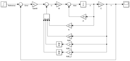
Figure 1.
The structure of the hybrid proportional double derivative and linear quadratic regulator (PD2-LQR) controller.
Let a state-space representation of a linear system is described as in Equation (8) below:
Now, from the above control structure, the control law of the system can be represented as in Equation (9) below:
From there, we can see that the gain KT is the total gain of the original LQR controller’s gain and the PD2 controller’s gain and is defined as Equation (10) below, and Ke is the system’s error gain.
E is the error signal between the output y and the reference input defined in Equation (11). Now, combining Equations (10) and (11), the control input of the system can be expressed as Equation (12) below:
4. Nature-Inspired Optimization Algorithm
In control theory, optimization is one of the essential tools that can be used to increase the controller’s performance. For instance, even though the same controller is used to control the same system, with a non-identical controller’s parameters, the controllers’ performance can differ. Therefore, proper tuning of the controller’s parameter is crucial to achieving a good system performance.
Nowadays, we can find an abundance of literature that has used an optimization tool for the controller’s parameter tuning. The evaluation of the control performance is determined based on the objective function. A few objective functions can be used to optimize the controller’s parameter, such as IAE, integral square error (ISE), integral time absolute error (ITAE), and integral time square error (ITSE). In this study, the objective function of IAE was used to optimize the controller’s parameters.
Nevertheless, the response that we get still yield a large overshoot and long settling time. Thus, we refine the objective function by adding other parameters which are the rise time (RT), percentage overshoot (OS), and steady-state error (SSE). The response shows faster rising time, short settling time, small overshoot, and small steady-state error using the new objective function. The IAE and the new objective function are given in Equations (13) and (14) respectively:
One of the nature-inspired optimization algorithms, GWO, is used to minimize the objective function described above. However, instead of using the original GWO, we proposed an improved version of GWO.
4.1. Overview of Grey Wolf Optimization (GWO) Algorithm
GWO is a type of swarm intelligent algorithm developed by Mirjalili, Mirjalili [84]. As in its name, GWO is inspired by the Grey Wolf’s social behavior (Canis lupus), moving in a pack hunting for the prey. The best candidate solution is called alpha, followed by the second-best and third best-called beta and delta in the hierarchy. The rest of the candidate solutions are assumed to be the omega where they will have to follow those three-best solutions. The mathematical model of the GWO is described in the following Equations (15)–(17):
where indicates the current iteration, and are the constant vectors, and is the position vector of the alpha, beta, and delta, and indicates the position vector of a grey wolf. The vectors and are determined as follows in Equations (18) and (19):
The controlling parameter is decreased linearly from 2 to 0 over the iteration course, and is the random vector in [0, 1]. The reduction of the controlling parameter, , was by using the information of the maximum iteration used in the algorithm, as presented in Equation (20) below,
The value of vectors and were chosen randomly in the range of [0, 1] using the rand () function in MATLAB. This randomness enables the wolves to reach any position randomly inside the search space around their target.
Overall, the process starts with initializing the random population of the Grey Wolf (candidate solution). Alpha, beta, and delta wolves estimate the prey’s probable position throughout the iteration. Each wolf updates its distance from the prey based on alpha, beta, and delta. The pseudo-code of the GWO algorithm is depicted in Figure 2.
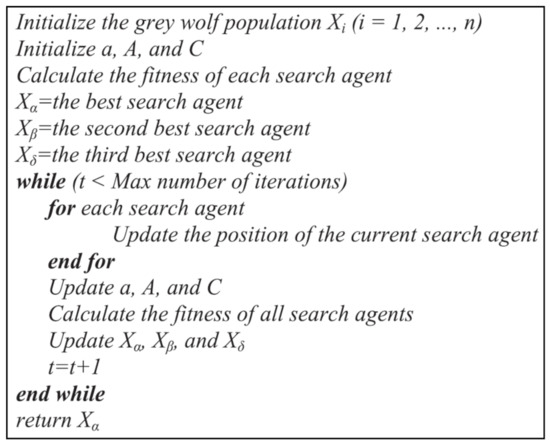
Figure 2.
Pseudo-code of Grey Wolf Optimization (GWO) algorithm.
4.2. Improved Grey Wolf Optimization (IGWO) Algorithm
The omegas must update their position based on the average position of alpha, beta, and delta. However, we know that the best candidate solution is alpha. Therefore, the alpha wolf is the nearest to the position of the prey. Although the beta and delta wolves are the second and third best candidate solutions, their position might be far from the alpha.
Therefore, using these three wolves’ average position might be unsuitable to describe the prey’s position. Thus, we proposed that the rest of the wolves must update their position more on the best candidate solution: alpha. The approach is where we introduce a weighting coefficient to the alpha, beta, and delta. Since alpha knows better about the prey’s location, the alpha’s weighting coefficient must be greater than beta and delta while beta must be greater than a delta but less than alpha, and delta is the lowest. The mathematical formulation described in Equation (17) can be changed as follows in Equation (21):
where is the weighting coefficient, and the chosen values are 0.5, 0.3, and 0.2, respectively. The weighting coefficient introduced in Equation (15) was determined based on the several simulations that we have undertaken. The idea of these values being introduced assumes the alpha wolf is the nearest to the prey’s location, followed by beta and delta since, in a hierarchy, alpha is the dominant wolf. Thus the weighting coefficient must always satisfy alpha > beta > delta but limit 1 when the total is summed up. However, we also must not ignore the effect of beta and delta. If the alpha value is too large and beta and delta are too low, it affects the search agent’s exploration phase (may be stuck in local optima). Thus, the relevant weighting coefficient for an alpha, beta, and delta was chosen as 0.5, 0.3, and 0.2. These values are proven to be suitable to use in the algorithm.
Moreover, an improvement has also been made on updating the search agents’ fitness (alpha, beta, and delta). Suppose we can see from the pseudo-code of the original GWO in Figure 2, in line 13. In that case, the original GWO updates their fitness independently and does not consider replacing the other wolves with the previous fitness value discarded. For instance, in the original GWO, if the current fitness of the alpha wolf is better than the previous fitness, then the previous fitness of the alpha wolf will be replaced by the current fitness, and the rest of the wolves (beta, delta, and gamma) will not be replaced.
However, we know that the alpha, beta, and delta wolves are the closest to the prey, and other wolves will have to update their position based on these three. Therefore, the updated law that we propose is that when the alpha’s fitness is replaced with the new fitness, then the beta wolf’s fitness must also be replaced with the previous alpha’s fitness. The same rule also goes for the delta wolf, where the previous beta’s fitness replaces it. With this method, all these three wolves will always be closer to the prey. The pseudo-code of the IGWO is presented in Figure 3.
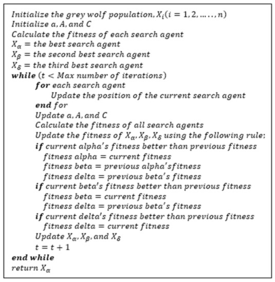
Figure 3.
Pseudo-code of improved Grey Wolf Optimization (IGWO) algorithm.
5. Result and Discussion
In this section, the performance of the proposed controller using a nature-inspired optimization algorithm called GWO is evaluated by utilizing a linear simulation of a quadrotor in terms of the trajectory tracking problem for altitude (z) and attitude (roll, pitch, and yaw) motion. An improved version of the GWO called IGWO was proposed and applied instead of the original one. The simulation was conducted in a MATLAB/SIMULINK simulation environment. When the simulation was conducted, the only response that we considered optimizing was the system’s transient response. Therefore, the control input value was set to be in the range of [0, 300]. This setting was made with the assumption that the controller directly controls the state of the system. Hence, no additional simulation concerning control effort was investigated in this work. The optimal parameters of the proposed controller obtained by the IGWO algorithm and the gain K with the Q and R matrices of the LQR controller are tabulated in Table 2 below.
Table 2.
The parameters of the controller (Model 13).
A comparative study was undertaken for two cases to verify the effectiveness of the proposed controller. The comparison was to realize the optimization algorithm’s effectiveness in tuning the controller parameter compared to traditional tuning methods such as manual or ZN methods. Moreover, we also wanted to show how much was the improvement achieved by the IGWO compared to the conventional GWO. Therefore, the PD2-LQR controller was optimized using the GWO and IGWO algorithm, while the other controller was optimized using the manual tuning method. First, we discuss the performance of the IGWO based PD2-LQR controller with the conventional controller. After that, we discuss the performance improvement made by the IGWO based PD2-LQR controller compare to GWO based PD2-LQR controller.
In the first part, since the proposed controller shows the best performance compared to the other controllers in every model simulated, the average value is presented for the discussion. For the second part, the best controller, the IGWO PD2-LQR controller, is assessed using 20 different models. The assessment is based on the performance comparison between the proposed controller with the existing result from those journals where the quadrotor’s parameters are obtained.
For both cases, the controller’s performance will be evaluated in terms of the rise time, settling time, percentage overshoot, steady-state error, and RMSE. The overall result is summarized in Table 3 and Table 4 for part one and Table 5 for part two in each section.
Table 3.
Performance comparison of the controller (in value).
Table 4.
Performance comparison of the controller (in percentage).
Table 5.
Performance of the controller using 20 different quadrotor models.
Finally, in the robustness test section, only the proposed controller will be used for simulating the effect of the system’s performance in the presence of a time-varying unknown external disturbance in the system and the sensor noise in the feedback loop.
5.1. Performance Comparison between Improved Grey Wolf Optimization (IGWO) Proportional Double Derivative and Linear Quadratic Regulator (PD2-LQR) Controller with a Conventional Controller and Original GWO-Based Controller
In the first study, the performance of the PD2-LQR controller using IGWO was analyzed by comparing with the conventional controllers, namely PD, PID, LQR, P-LQR, PD-LQR, and PD2-LQR. Then, we separately discuss the performance of the optimization-based controller (GWO PD2-LQR and IGWO PD2-LQR).
One of these studies aims to realize this nature-inspired optimization algorithm’s ability to obtain an optimal controller’s parameter to control the quadrotor with improved performance. The reference step input given to the quadrotor is (1,1,1,1) with the initial condition of (0,0,0,0) for roll, pitch, yaw, and altitude.
The step response of the system in the time domain for roll, pitch, yaw, and altitude motion are plotted as shown in Figure 4a–d, respectively.
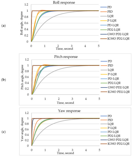
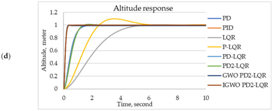
Figure 4.
Step response of the system, (a) roll, (b) pitch, (c) yaw, and (d) altitude motion.
The figure shows that all motion controllers have successfully driven the quadrotor to reach and stabilize it at the desired reference altitude and angle. The controllers’ performance in their respective motions is summarized in Table 3, and the percentage improvement is outlined in Table 4 below.
By carefully observing the step response in Figure 4 and the average values in Table 3 we can see that IGWO PD2-LQR controller achieves much better performance than the conventional controllers in term of the rise time and settling time in all four motions. The percentage overshoot is dominated by the PD controller in roll and pitch motions, while in yaw and altitude motions it is dominated by the IGWO PD2-LQR controller.
For steady-state error, the PD controller shows better precision in tracking the desired reference in all four motions. IGWO PD2-LQR controller produces lower RMSE in roll, pitch, and yaw motions, while the PD2-LQR controller is better in altitude motion. The overall worst performance is exhibited by the LQR controller that gave the slowest rise time and settling time and the highest steady-state error and RMSE in roll, pitch, and yaw motions.
However, the altitude motion LQR controller only performed worse in terms of rise time and settling time, while the worst steady-state error is produced by the PD2-LQR controller and the worst RMSE produced by the IGWO PD2-LQR controller. PID controller is the worst in roll, pitch, and yaw motions for percentage overshoot, while the P-LQR controller is the worst in altitude motion.
In terms of the rise time, IGWO PD2-LQR exhibit the fastest response with 0.0317 s, 0.0322 s, 0.0182 s, and 0.1365 s, while the LQR controller had the slowest response with 2.1045 s, 2.1047 s, 2.0923 s, and 2.7063 s in roll, pitch, yaw, and altitude motions respectively. We can see that up to 90% improvement can be made if the IGWO PD2-LQR controller is used. Although the slowest response is about 2 s, other controllers show rise time ranging between 0.4 s to 0.8 s.
The same result can be seen for the settling time where the IGWO PD2-LQR controller shows the shortest time (0.0526 s, 0.0533 s, 0.0308 s, and 0.2245 s) to settle the desired reference angle and altitude. The longest time taken to settle is produced by the LQR controller with 3.4910 s, 3.4923 s, 3.4511 s, and 4.4146 s compared with the IGWO PD2-LQR controller in roll, pitch, yaw, and altitude motion, respectively. For the other controllers, the settling time is ranging from 0.7 s to 3.9 s.
The evaluation of the percentage overshoot reveals that two controllers have the lowest overshoot. In roll and pitch motion, the PD controller is dominated with 0.0003% in both motions, while the PID controller produces the worst overshoot with 1.1111% and 1.1391%, respectively. The IGWO PD2-LQR controller is the best for yaw and altitude motions, with 0.0018% and 0.0000%.
The PID controller produced the highest overshoot (0.5967%) in yaw motion and the P-LQR controller (8.0415%) in altitude motion. Note that for the first two motions the IGWO PD2-LQR controller has the second-best performance after the PD controller. It is worth mentioning that if we made a comparison, not as a percentage, we find that the value is minimal. Thus, we can neglect those values and assume that both controllers have the same performance. The rest of the controllers range from 0.1% to 1.0%.
As for the steady-state error, the PD controller is dominated in all four motions with a 0.0000 error, while the LQR controller is the worst with 0.0054 in roll and pitch motions and 0.0057 in yaw motion. In altitude motion, the PD2-LQR controller produces the highest error with 0.0039. However, the value of steady-state error for all the controllers is minimal, less than 0.005. Therefore, these values can be neglected and can be approximated to be ~0.
Regarding the RMSE, the IGWO PD2-LQR controller produces the lowest value with 0.2207, 0.2224, and 0.1751 in roll, pitch, and yaw motion, respectively, while the PD2-LQR controller is the best in altitude motion with 0.3223. The highest error is produced by the LQR controller (0.4562, 0.4567, and 0.3983) in roll, pitch, and yaw motions, while the IGWO PD2-LQR controller (0.3754) is worst in altitude motion. Although the IGWO PD2-LQR controller is the worst in altitude motion, the difference with the lowest error is only 0.0531, which can be considered small. Thus, the RMSE of the IGWO PD2-LQR controller is still acceptable.
Next, if we compare GWO PD2-LQR and IGWO PD2-LQR controller performance, we can see that the IGWO PD2-LQR controller mostly performed better than the GWO PD2-LQR controller. These two controllers’ value shows less variance since both controllers use an optimization algorithm in obtaining the controller’s parameters. However, the IGWO PD2-LQR controller is still showing a significant improvement compared to the GWO PD2-LQR controller.
In terms of the rise time and settling time, the IGWO PD2-LQR controller is dominated for roll, pitch, and yaw motions, while the GWO PD2-LQR controller is the best in altitude motion. The percentage overshoot of the IGWO PD2-LQR controller is the best in roll and pitch motions, while the GWO PD2-LQR controller is best in yaw motion.
Nevertheless, both controllers produce zero percent overshoot in altitude motion. In steady-state error, the IGWO PD2-LQR controller is better in all four motions. IGWO PD2-LQR controller dominates RMSE, roll, pitch, and yaw motion while the GWO PD2-LQR controller dominates in altitude motion.
5.2. Performance Comparison of IGWO PD2-LQR Controller with Different Quadrotor’s Parameters
In this second study, the controller’s performance was analyzed by using 20 different quadrotor parameters. This study aims to show the effectiveness and compatibility of the proposed controller with different models. The parameters of the quadrotor used in this simulation are presented in Table 1. The simulation result is tabulated in Table 4 below, which described the performance characteristic in terms of the rise time, settling time, percentage overshoot, steady-state error, and RMSE of the IGWO PD2-LQR controller.
Based on Table 5, we can see that the IGWO PD2-LQR controller’s performance can perform much better than those in the references cited. Our proposed controller can stabilize the quadrotor in a short period with faster rising time and lower overshoot, and minimal steady-state error. All the models used in the simulation are suitable for our proposed controller.
5.3. Robustness Test
In a real-world application, when the quadrotor is flying in an outdoor environment, it is always subjected to an unknown external disturbance such as wind gust [72]. Furthermore, in real implementation on the quadrotor system, feedback data are always noisy and distorted due to the mechanical vibration arising from the sensor [85]. Therefore, to test the controller’s robustness under these circumstances, another two separate simulations were conducted to consider the external disturbance and sensor noise.
In the first test, the quadrotor was assumed to fly in an environment where an external disturbance was present throughout the flight time. The unknown external disturbance force was modeled using a sinusoidal wave function with the amplitude of 1 and the frequency of 8 Hz, as shown in Equation (22) below. Then, the external disturbance modeled was injected into the system for both altitude and attitude subsystem. The plot of the disturbance’s model is depicted in Figure 5 below.
d(t) = 1 sin(8t)
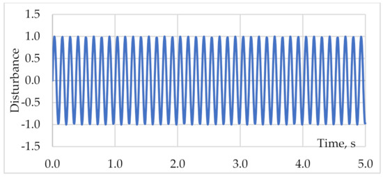
Figure 5.
Unknown external disturbance variation over time.
The step response of the system using the proposed IGWO PD2-LQR controller in the presence of unknown external disturbance are shown in Figure 6a–d for the roll, pitch, yaw, and altitude motion, respectively. From these figures, it is observed that the controller was able to control and stabilize the quadrotor at the desired reference altitude and angle without significant degradation in its performance. However, it can still be noticed that the system is attenuating slightly around the nominal point since it was repeatedly subjected to external disturbance. However, if we can see from the altitude and attitude error of the system’s response in Figure 7, the error produced is not too large, and the deviation is only around ±0.01° for roll, pitch, and yaw motions respectively, and ±0.03 m for the altitude motion.
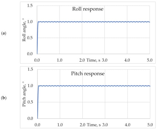
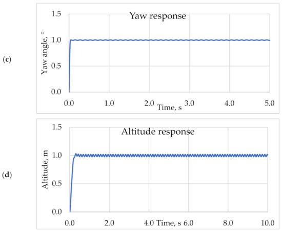
Figure 6.
The step response of the system in the presence of unknown external disturbance, (a) roll, (b) pitch, (c) yaw, and (d) altitude motions.
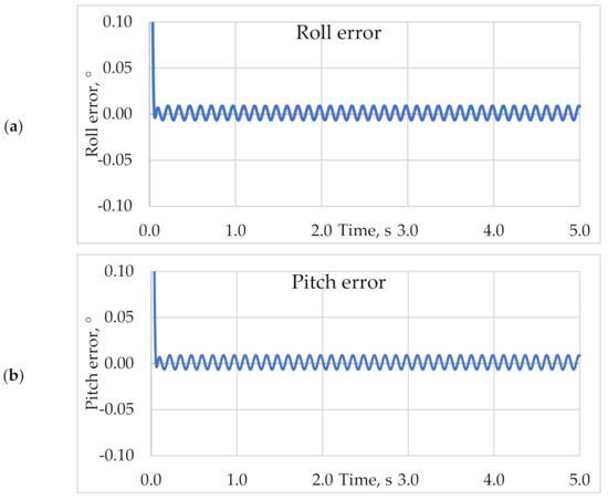
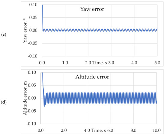
Figure 7.
The response of the altitude and attitude error of the system, (a) roll, (b) pitch, (c) yaw, and (d) altitude motions.
In the second test, we assume that the system is corrupted with the noisy signal coming back from the feedback loop sensor. White Gaussian noise with a zero mean value and variance of 0.01 was applied to simulate the sensor noise present in the feedback signal. The generated noise was fed into the feedback loop for both the altitude and attitude subsystems. The plot for the generated sensor noise is presented in Figure 8.
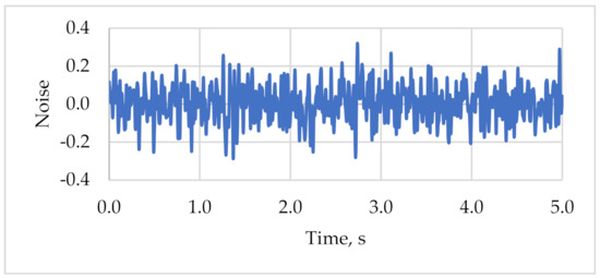
Figure 8.
Sensor noise signal.
The step response of the system using the proposed IGWO PD2-LQR controller in the presence of sensor noise are shown in Figure 9a–d for the roll, pitch, yaw, and altitude motions respectively. From these figures, the controller observed that the controller could control and stabilize the quadrotor at the desired reference altitude and angle without significant degradation in its performance. Nonetheless, it still can be noted that the system is attenuating slightly around the nominal point since it was constantly subjected to sensor noise. However, if we can see from the altitude and attitude error of the system’s response in Figure 10, the error produced is not too large, and the deviation is only around ±0.04° for roll, pitch, and yaw motions, respectively, and ±0.03 m for the altitude motion.
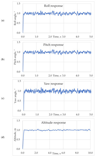
Figure 9.
The step response of the system in the presence of sensor noise, (a) roll, (b) pitch, (c) yaw, and (d) altitude motions.
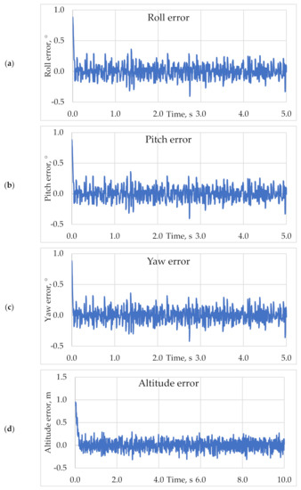
Figure 10.
The response of the altitude and attitude error of the system, (a) roll, (b) pitch, (c) yaw, and (d) altitude motions.
5.4. Summary
In the previous subsection, the controllers’ simulation result in all four motions, roll, pitch, yaw, and altitude motions, was presented and discussed. A comparative study was undertaken with several conventional controllers to demonstrate the proposed controller’s effectiveness, namely PD, PID, LQR, P-LQR, PD-LQR, and PD2-LQR. Moreover, since the proposed controller here uses an improved version of the Grey Wolf Optimization algorithm (IGWO), we also compare our result with the original GWO using the PD2-LQR controller.
We also compared our controller’s performance with 20 different models from the references cited in Table 1. Overall, we can see that mostly the IGWO PD2-LQR controller has a superior performance compared to the other controllers. It is essential to mention that the GWO PD2-LQR and IGWO PD2-LQR controllers’ performance show less variance. This is because both controllers use an optimization algorithm to find an optimal controller’s parameter; therefore, both controllers can have equally good performance compared to the others. However, the IGWO PD2-LQR controller still shows supremacy against the GWO PD2-LQR controller regarding the rise time, settling time, percentage overshoot, steady-state error, and RMSE in most of the motion.
Finally, to test the proposed controller’s robustness, a simulation subjected to the unknown external disturbance and sensor noise was conducted to simulate a real-world application. The external disturbance was modeled using the sinusoidal wave function with an amplitude of 1 and a frequency of 8 Hz. The sensor noise was modeled using white Gaussian noise with a zero mean value and variance of 0.01. The external disturbance and the sensor noise were applied for the simulation period. The simulation result shows that the proposed controller can still work effectively even under these circumstances with minimal error produced.
This study only conducted a simulation work to prove the IGWO PD2-LQR controller’s superior performance. However, according to several studies that compare simulation and experimental work, it was found that the performance is quite different in a real implementation. Nonetheless, the differences between these two works are not too great. Therefore, we present a few references that work in both the simulation and experimental studies of the quadrotor control and stabilization to support our findings.
Raza and Gueaieb [29] presented their findings that the pitch and roll angle are within [−3, +4]° for simulation while [−8, +7] and [−6, +12]° in pitch and roll, respectively, for experimental work. Li and Li [86] found that the quadrotor’s attitude angle fluctuated at ±5° from a 0.1° reference angle. In work by Burggräf, Pérez Martínez [9], the stabilization time for the attitude angle was around 1.3 s for simulation, while for an experiment, it took 2.2 s to stabilize. The results of Rich, Elia [87] show that simulation and experimental work are almost the same, with approximately less than 10 s to settle at the desired altitude. Hong and Nguyen [88] undertook the position control of the quadrotor using a gain-scheduling PD controller. They found that the time taken to reach the desired reference was 9.55 s for simulation while 17.5 s for experimental.
We can conclude that simulation and experimental work performance differs only a few degree/meters based on these references. Thus, our result is still good even if we consider these differences.
6. Conclusions
In this paper, modeling and controlling the quadrotor for altitude (z) and attitude (roll, pitch, and yaw) motion were designed and simulated. The dynamic model of the quadrotor was derived based on the Newton–Euler theorem. A hybrid PD2-LQR controller was designed, and the parameters were tuned using a nature-inspired optimization algorithm called Grey Wolf Optimizer (GWO). However, an improved version of GWO was used instead of the original. The proposed controller’s performance in terms of the rise time, settling time, percentage overshoot, steady-state error, and RMSE was compared with the conventional controllers, namely PD, PID, LQR, P-LQR, PD-LQR, PD2-LQR, and GWO PD2-LQR.
We also compared the result with different models obtained from 20 different references. The simulation results show that the proposed IGWO PD2-LQR controller improved the quadrotor’s performance in all four motions more than the conventional controllers. Although the GWO PD2-LQR controller outperformed the IGWO PD2-LQR controller in altitude motion, the difference between those values was minimal. Furthermore, a robustness test of the proposed controller was also conducted to simulate real-world application. The simulation was undertaken with the assumption of the quadrotor being continuously subjected to an unknown external disturbance and sensor noise. The external disturbance was modeled using the sinusoidal wave function with an amplitude of 1 and a frequency of 8 Hz. The sensor noise was modeled using white Gaussian noise with a zero mean value and variance of 0.01. The simulation result under these circumstances showed that the proposed controller could still work effectively with only minimal error produced. Therefore, we can say that the IGWO PD2-LQR controller’s overall performance is superior to the others.
Author Contributions
Conceptualization, M.N.S. and P.R.; methodology, M.N.S., P.R. and N.M.S.; software, M.N.S.; validation, M.N.S. and P.R.; formal analysis, M.N.S. and P.R.; investigation, M.N.S. and P.R.; resources, M.N.S. and P.R.; data curation, M.N.S. and P.R.; writing—original draft preparation, M.N.S., P.R. and N.M.S.; visualization, M.N.S.; supervision and project administration, P.R. and N.M.S.; funding acquisition, P.R. and N.M.S. All authors have read and agreed to the published version of the manuscript.
Funding
This research was funded by Universiti Sains Malaysia Grant No. 1001/PAERO/8014108, and the APC was funded by Universiti Sains Malaysia.
Institutional Review Board Statement
Not applicable.
Informed Consent Statement
Not applicable.
Data Availability Statement
The authors confirm that the data supporting the findings of this study are available within the article.
Acknowledgments
The authors thank the editor and anonymous reviewers for their helpful comments and valuable suggestions.
Conflicts of Interest
The authors declare no conflict of interest.
References
- Badr, S.; Mehrez, O.; Kabeel, A.E. A design modification for a quadrotor UAV: Modeling, control and implementation. Adv. Robot. 2019, 33, 13–32. [Google Scholar] [CrossRef]
- Jiang, F.; Pourpanah, F.; Hao, Q. Design, Implementation, and Evaluation of a Neural-Network-Based Quadcopter UAV Sys-tem. IEEE Trans. Ind. Electron. 2020, 67, 2076–2085. [Google Scholar] [CrossRef]
- Noormohammadi-Asl, A.; Esrafilian, O.; Arzati, M.A.; Taghirad, H.D. System identification and H∞-based control of quadrotor attitude. Mech. Syst. Signal Process. 2020, 135, 106358. [Google Scholar] [CrossRef]
- Hasseni, S.-E.-I.; Abdou, L.; Glida, H.-E. Parameters tuning of a quadrotor PID controllers by using nature-inspired algorithms. Evol. Intell. 2019, 1–13. [Google Scholar] [CrossRef]
- Khatoon, S.; Nasiruddin, I.; Shahid, M. Design and Simulation of a Hybrid PD-ANFIS Controller for Attitude Tracking Control of a Quadrotor UAV. Arab. J. Sci. Eng. 2017, 42, 5211–5229. [Google Scholar] [CrossRef]
- Xiu, C.; Liu, F.; Xu, G. General model and improved global sliding mode control of the four-rotor aircraft. Proc. Inst. Mech. Eng. Part I J. Syst. Control. Eng. 2017, 232, 383–389. [Google Scholar] [CrossRef]
- Kuantama, E.; Vesselenyi, T.; Dzitac, S.; Tarca, R. PID and Fuzzy-PID Control Model for Quadcopter Attitude with Disturbance Parameter. Int. J. Comput. Commun. Control. 2017, 12, 519–532. [Google Scholar] [CrossRef]
- El Gmili, N.; Mjahed, M.; el Kari, A.; Ayad, H. Particle Swarm Optimization and Cuckoo Search-Based Approaches for Quadrotor Control and Trajectory Tracking. Appl. Sci. 2019, 9, 1719. [Google Scholar] [CrossRef]
- Burggräf, P.; Martínez, A.R.P.; Roth, H.; Wagner, J. Quadrotors in factory applications: Design and implementation of the quadrotor’s P-PID cascade control system. SN Appl. Sci. 2019, 1, 722. [Google Scholar] [CrossRef]
- Erkol, H.O. Attitude controller optimization of four-rotor unmanned air vehicle. Int. J. Micro Air Veh. 2017, 10, 42–49. [Google Scholar] [CrossRef]
- Abdelhay, S.; Zakriti, A. Modeling of a Quadcopter Trajectory Tracking System Using PID Controller. Procedia Manuf. 2019, 32, 564–571. [Google Scholar] [CrossRef]
- Okyere, E.; Bousbaine, A.; Poyi, G.T.; Joseph, A.K.; Andrade, J.M. LQR controller design for quad-rotor helicopters. J. Eng. 2019, 2019, 4003–4007. [Google Scholar] [CrossRef]
- Martins, L.; Cardeira, C.; Oliveira, P. Linear Quadratic Regulator for Trajectory Tracking of a Quadrotor. IFAC-PapersOnLine 2019, 52, 176–181. [Google Scholar] [CrossRef]
- Shah, J.; Okasha, M.; Faris, W. Gain scheduled integral linear quadratic control for quadcopter. Int. J. Eng. Technol. 2018, 7, 81–85. [Google Scholar] [CrossRef]
- Jia, Z.; Yu, J.; Mei, Y.; Chen, Y.; Shen, Y.; Ai, X. Integral backstepping sliding mode control for quadrotor helicopter under external uncertain disturbances. Aerosp. Sci. Technol. 2017, 68, 299–307. [Google Scholar] [CrossRef]
- Basri, M.A.M.; Husain, A.R.; Danapalasingam, K.A. Nonlinear Control of an Autonomous Quadrotor Unmanned Aerial Vehicle using Backstepping Controller Optimized by Particle Swarm Optimization. J. Eng. Sci. Technol. Rev. 2015, 8, 39–45. [Google Scholar] [CrossRef]
- Mofid, O.; Mobayen, S. Adaptive sliding mode control for finite-time stability of quad-rotor UAVs with parametric uncertainties. ISA Trans. 2018, 72, 1–14. [Google Scholar] [CrossRef]
- Castillo-Zamora, J.J.; Camarillo-Gomez, K.A.; Perez-Soto, G.I.; Rodriguez-Resendiz, J. Comparison of PD, PID and Sliding-Mode Position Controllers for V–Tail Quadcopter Stability. IEEE Access 2018, 6, 38086–38096. [Google Scholar] [CrossRef]
- Pan, F.; Liu, L.; Xue, D. Optimal PID controller design with Kalman filter for Qball-X4 quad-rotor unmanned aerial vehicle. Trans. Inst. Meas. Control. 2017, 39, 1785–1797. [Google Scholar] [CrossRef]
- Tanveer, M.; Ahmed, S.F.; Hazry, D.; Warsi, F.A.; Joyo, M.K. Stabilized controller design for attitude and altitude controlling of quad-rotor under disturbance and noisy condi-tions. Am. J. Appl. Sci. 2013, 10, 819–831. [Google Scholar] [CrossRef]
- Moreno-Valenzuela, J.; Perez-Alcocer, R.; Guerrero-Medina, M.; Dzul, A. Nonlinear PID-Type Controller for Quadrotor Trajectory Tracking. IEEE/ASME Trans. Mechatron. 2018, 23, 2436–2447. [Google Scholar] [CrossRef]
- Zhi, Y.; Li, G.; Song, Q.; Yu, K.; Zhang, J. Flight control law of unmanned aerial vehicles based on robust servo linear quadratic regulator and Kalman filtering. Int. J. Adv. Robot. Syst. 2017, 14. [Google Scholar] [CrossRef]
- Alkamachi, A.; Erçelebi, E. H∞ control of an overactuated tilt rotors quadcopter. J. Central South Univ. 2018, 25, 586–599. [Google Scholar] [CrossRef]
- Bonna, R.; Camino, J. Trajectory Tracking Control of a Quadrotor Using Feedback Linearization. In Proceedings of the XVII International Symposium on Dynamic Problems of Mechanics (DINAME), Natal, Brazil, 22–27 February 2015. [Google Scholar]
- Huo, X.; Huo, M.; Karimi, H.R. Attitude Stabilization Control of a Quadrotor UAV by Using Backstepping Approach. Math. Probl. Eng. 2014, 2014, 1–9. [Google Scholar] [CrossRef]
- Cömert, C.; Kasnakoğlu, C. Comparing and Developing PID and Sliding Mode Controllers for Quadrotor. Int. J. Mech. Eng. Robot. Res. 2017, 6, 194–199. [Google Scholar] [CrossRef]
- Mohammadi, M.; Shahri, A.M. Adaptive Nonlinear Stabilization Control for a Quadrotor UAV: Theory, Simulation and Experimentation. J. Intell. Robot. Syst. 2013, 72, 105–122. [Google Scholar] [CrossRef]
- Dou, J.; Kong, X.; Wen, B. Altitude and attitude active disturbance rejection controller design of a quadrotor unmanned aerial vehicle. Proc. Inst. Mech. Eng. Part G J. Aerosp. Eng. 2017, 231, 1732–1745. [Google Scholar] [CrossRef]
- Raza, S.; Gueaieb, W. Intelligent Flight Control of an Autonomous Quadrotor. Motion Control 2010, 1, 245–264. [Google Scholar]
- Xiang, T.; Jiang, F.; Hao, Q.; Cong, W. Adaptive flight control for quadrotor UAVs with dynamic inversion and neural networks. In Proceedings of the 2016 IEEE International Conference on Multisensor Fusion and Integration for Intelligent Systems (MFI), Baden-Baden, Germany, 19–21 September 2016. [Google Scholar]
- Kennedy, J.; Eberhart, R. Particle swarm optimization. In Proceedings of the ICNN’95- International Conference on Neural Networks, Perth, WA, Australia, 27 November–1 December 1995. [Google Scholar]
- Goldberg, D.E.; Holland, J.H. Genetic Algorithms and Machine Learning. Mach. Learn. 1988, 3, 95–99. [Google Scholar] [CrossRef]
- Dorigo, M.; Caro, G.D. Ant colony optimization: A new meta-heuristic. In Proceedings of the 1999 Congress on Evolutionary Computation-CEC99 (Cat. No. 99TH8406), Washington, DC, USA, 6–9 July 1999. [Google Scholar]
- Mohan, B.C.; Baskaran, R. A survey: Ant Colony Optimization based recent research and implementation on several engineering domain. Expert Syst. Appl. 2012, 39, 4618–4627. [Google Scholar] [CrossRef]
- Karaboga, D. An Idea Based on Honey Bee Swarm for Numerical Optimization; Technical Report-TR06; Erciyes University: Talas, Turkey, 2005. [Google Scholar]
- Karaboga, D.; Gorkemli, B.; Ozturk, C.; Karaboga, N. A comprehensive survey: Artificial bee colony (ABC) algorithm and applications. Artif. Intell. Rev. 2014, 42, 21–57. [Google Scholar] [CrossRef]
- Yang, X.; Suash, D. Cuckoo Search via Lévy flights. In Proceedings of the 2009 World Congress on Nature & Biologically Inspired Computing (NaBIC), Coimbatore, India, 9–11 December 2009. [Google Scholar]
- Joshi, A.S.; Kulkarni, O.; Kakandikar, G.; Nandedkar, V.M. Cuckoo Search Optimization—A Review. Mater. Today: Proc. 2017, 4, 7262–7269. [Google Scholar] [CrossRef]
- Saud, L.J.; Hasan, A.F. Design of an Optimal Integral Backstepping Controller for a Quadcopter. J. Eng. 2018, 24, 46–65. [Google Scholar] [CrossRef]
- Imane, S.; Mostafa, M.; Hassan, A.; Abdeljalil, E.K. Control of a quadcopter using reference model and genetic algorithm methods. In Proceedings of the 2015 Third World Conference on Complex Systems (WCCS), Marrakech, Morocco, 23–25 November 2015. [Google Scholar]
- Ding, L.; Wang, Z. A Robust Control for an Aerial Robot Quadrotor under Wind Gusts. J. Robot. 2018, 2018, 1–8. [Google Scholar] [CrossRef]
- Merabti, H.; Bouchachi, I.; Belarbi, K. Nonlinear model predictive control of quadcopter. In Proceedings of the 2015 16th International Conference on Sciences and Techniques of Automatic Control and Computer Engineering (STA), Monastir, Tunisia, 21–23 December 2015. [Google Scholar]
- Yazid, E.; Garratt, M.; Santoso, F. Position control of a quadcopter drone using evolutionary algorithms-based self-tuning for first-order Takagi–Sugeno–Kang fuzzy logic autopilots. Appl. Soft Comput. 2019, 78, 373–392. [Google Scholar] [CrossRef]
- Adriansyah, A.; Amin, S.H.M.; Minarso, A.; Ihsanto, E. Improvement of quadrotor performance with flight control system using particle swarm proportion-al-integral-derivative (PS-PID). J. Teknol. 2017, 79, 121–128. [Google Scholar]
- Nada El, G.; Ayad, H. Quadrotor Identification through the Cooperative Particle Swarm Optimization-Cuckoo Search Approach. Comput. Intell. Neurosci. CIN 2019, 2019, 10. [Google Scholar]
- Khuwaja, K.; Lighari, N.-U.-Z.; Tarca, I.C.; Tarca, R.C. PID Controller Tuning Optimization with Genetic Algorithms for a Quadcopter. Recent Innov. Mechatron. 2018, 5, 5. [Google Scholar] [CrossRef]
- Alkamachi, A.; Erçelebi, E. Modelling and Genetic Algorithm Based-PID Control of H-Shaped Racing Quadcopter. Arab. J. Sci. Eng. 2017, 42, 2777–2786. [Google Scholar] [CrossRef]
- Salgotra, R.; Singh, U.; Sharma, S. On the improvement in grey wolf optimization. Neural Comput. Appl. 2019, 32, 3709–3748. [Google Scholar] [CrossRef]
- Jayabarathi, T.; Raghunathan, T.; Adarsh, B.R.; Suganthan, P.N. Economic dispatch using hybrid grey wolf optimizer. Energy 2016, 111, 630–641. [Google Scholar] [CrossRef]
- Kamboj, V.K.; Bath, S.K.; Dhillon, J.S. Solution of non-convex economic load dispatch problem using Grey Wolf Optimizer. Neural Comput. Appl. 2016, 27, 1301–1316. [Google Scholar] [CrossRef]
- Sultana, U.; Khairuddin, A.B.; Mokhtar, A.S.; Zareen, N.; Sultana, B. Grey wolf optimizer based placement and sizing of multiple distributed generation in the distribution system. Energy 2016, 111, 525–536. [Google Scholar] [CrossRef]
- Nahak, N.; Mallick, R.K. Damping of power system oscillations by a novel DE-GWO optimized dual UPFC controller. Eng. Sci. Technol. Int. J. 2017, 20, 1275–1284. [Google Scholar] [CrossRef]
- Zhang, S.; Zhou, Y. Grey Wolf Optimizer Based on Powell Local Optimization Method for Clustering Analysis. Discret. Dyn. Nat. Soc. 2015, 2015, 1–17. [Google Scholar] [CrossRef]
- Emary, E.; Zawbaa, H.M.; Hassanien, A.E. Binary grey wolf optimization approaches for feature selection. Neurocomputing 2016, 172, 371–381. [Google Scholar] [CrossRef]
- Das, K.R.; Das, D.; Das, J. Optimal tuning of PID controller using GWO algorithm for speed control in DC motor. In Proceedings of the 2015 International Conference on Soft Computing Techniques and Implementations (ICSCTI), Faridabad, India, 8–10 October 2015. [Google Scholar]
- Kuppusamy, M.S.; Sivasubramanian, M.; Pannerselvam, G.; Jebasingh Kirubakaran, S.J. Grey wolf optimization algorithm based speed control of three phase induction motor. Int. J. Comput. Technol. Appl. 2016, 9, 3889–3895. [Google Scholar]
- Yadav, S.; Verma, S.; Nagar, S. Optimized PID Controller for Magnetic Levitation System. IFAC-PapersOnLine 2016, 49, 778–782. [Google Scholar] [CrossRef]
- Ramadan, H. Optimal fractional order PI control applicability for enhanced dynamic behavior of on-grid solar PV systems. Int. J. Hydrogen Energy 2017, 42, 4017–4031. [Google Scholar] [CrossRef]
- Yusof, Y.; Mustaffa, Z. Time Series Forecasting of Energy Commodity Using Grey Wolf Optimizer. In Proceedings of the 2015 International Multi Conference of Engineers and Computer Scientists (IMECS’15), Hong Kong, China, 18 March 2015. [Google Scholar]
- Biyanto, T.R.; Afdanny, N.; Alfarisi, M.S.; Haksoro, T.; Kusumaningtyas, S.A. Optimization of acid gas sweetening plant based on least squares—Support Vector Machine (LS-SVM) Model and Grey Wolf Optimizer (GWO). In Proceedings of the 2016 International Seminar on Sensors, Instrumentation, Measurement and Metrology (ISSIMM), Malang, Indonesia, 10–11 August 2016. [Google Scholar]
- Zainal, N.A.; Mustaffa, Z. Developing a gold price predictive analysis using Grey Wolf Optimizer. In Proceedings of the 2016 IEEE Student Conference on Research and Development (SCOReD), Kuala Lumpur, Malaysia, 13–14 December 2016. [Google Scholar]
- Zhang, S.; Zhou, Y. Template matching using grey wolf optimizer with lateral inhibition. Optik 2017, 130, 1229–1243. [Google Scholar] [CrossRef]
- Sujatha, K.; Punithavathani, D.S. Optimized ensemble decision-based multi-focus imagefusion using binary genetic Grey-Wolf optimizer in camera sensor networks. Multimed. Tools Appl. 2017, 77, 1735–1759. [Google Scholar] [CrossRef]
- Dudani, K.; Chudasama, A. Partial discharge detection in transformer using adaptive grey wolf optimizer based acoustic emission technique. Cogent Eng. 2016, 3, 1256083. [Google Scholar] [CrossRef]
- Zhang, S.; Zhou, Y.; Li, Z.; Pan, W. Grey wolf optimizer for unmanned combat aerial vehicle path planning. Adv. Eng. Softw. 2016, 99, 121–136. [Google Scholar] [CrossRef]
- Khalilpourazari, S.; Khalilpourazary, S. Optimization of production time in the multi-pass milling process via a Robust Grey Wolf Optimizer. Neural Comput. Appl. 2016, 29, 1321–1336. [Google Scholar] [CrossRef]
- Karnavas, Y.L.; Chasiotis, I.E. PMDC coreless micro-motor parameters estimation through Grey Wolf Optimizer. In Proceedings of the 2016 XXII International Conference on Electrical Machines (ICEM), Lausanne, Switzerland, 4–7 September 2016. [Google Scholar]
- Verma, S.K.; Yadav, S.; Nagar, S.K. Optimization of Fractional Order PID Controller Using Grey Wolf Optimizer. J. Control. Autom. Electr. Syst. 2017, 28, 314–322. [Google Scholar] [CrossRef]
- Song, X.; Tang, L.; Zhao, S.; Zhang, X.; Li, L.; Huang, J.; Cai, W. Grey Wolf Optimizer for parameter estimation in surface waves. Soil Dyn. Earthq. Eng. 2015, 75, 147–157. [Google Scholar] [CrossRef]
- Doukhi, O.; Fayjie, A.R.; Lee, D.J. Intelligent Controller Design for Quad-Rotor Stabilization in Presence of Parameter Variations. J. Adv. Transp. 2017, 2017, 1–10. [Google Scholar] [CrossRef]
- Rubí, B.; Pérez, R.; Morcego, B. A Survey of Path Following Control Strategies for UAVs Focused on Quadrotors. J. Intell. Robot. Syst. 2020, 98, 241–265. [Google Scholar] [CrossRef]
- Doukhi, O.; Lee, D.J. Neural Network-based Robust Adaptive Certainty Equivalent Controller for Quadrotor UAV with Un-known Disturbances. Int. J. Control Autom. Syst. 2019, 17, 2365–2374. [Google Scholar] [CrossRef]
- Barikbin, B.; Fakharian, A. Trajectory tracking for quadrotor UAV transporting cable-suspended payload in wind presence. Trans. Inst. Meas. Control. 2019, 41, 1243–1255. [Google Scholar] [CrossRef]
- Miranda-Colorado, R.; Aguilar, L.T. Robust PID control of quadrotors with power reduction analysis. ISA Trans. 2020, 98, 47–62. [Google Scholar] [CrossRef]
- Nguyen, N.P.; Hong, S.K. Sliding Mode Thau Observer for Actuator Fault Diagnosis of Quadcopter UAVs. Appl. Sci. 2018, 8, 1893. [Google Scholar] [CrossRef]
- Wu, Y.; Hu, K.; Sun, X.-M.; Yuhu, W.; Kaijian, H.; Ximing, S. Modeling and Control Design for Quadrotors: A Controlled Hamiltonian Systems Approach. IEEE Trans. Veh. Technol. 2018, 67, 11365–11376. [Google Scholar] [CrossRef]
- Dong, J.; He, B. Novel Fuzzy PID-Type Iterative Learning Control for Quadrotor UAV. Sensors 2018, 19, 24. [Google Scholar] [CrossRef]
- Siti, I.; Mjahed, M.; Ayad, H.; El Kari, A. New Trajectory Tracking Approach for a Quadcopter Using Genetic Algorithm and Reference Model Methods. Appl. Sci. 2019, 9, 1780. [Google Scholar] [CrossRef]
- Thanh, H.L.N.N.; Hong, S.K. Quadcopter Robust Adaptive Second Order Sliding Mode Control Based on PID Sliding Surface. IEEE Access 2018, 6, 66850–66860. [Google Scholar] [CrossRef]
- Thanh, H.; Hong, S.K. Robust Dynamic Sliding Mode Control-Based PID–Super Twisting Algorithm and Disturbance Observer for Second-Order Nonlinear Systems: Application to UAVs. Electronics 2019, 8, 760. [Google Scholar]
- Moussa, L. Robust Integral Terminal Sliding Mode Control for Quadrotor UAV with External Disturbances. Int. J. Aerosp. Eng. 2019, 2019, 1–10. [Google Scholar]
- Nadda, S.; Swarup, A. On adaptive sliding mode control for improved quadrotor tracking. J. Vib. Control. 2018, 24, 3219–3230. [Google Scholar] [CrossRef]
- Ru, P.; Subbarao, K. Nonlinear Model Predictive Control for Unmanned Aerial Vehicles. Aerospace 2017, 4, 31. [Google Scholar] [CrossRef]
- Mirjalili, S.; Mirjalili, S.M.; Lewis, A. Grey Wolf Optimizer. Adv. Eng. Softw. 2014, 69, 46–61. [Google Scholar] [CrossRef]
- Tanveer, M.H.; Hazry, D.; Ahmed, S.F.; Joyo, M.K.; Warsi, F.A.; Kamarudin, H.; Wan, K.; Razlan, Z.M.; Hussain, A.T. Feedback sensor noise rejection control strategy for quadrotor UAV system. AIP Conf. Proc. 2015, 1660, 070053. [Google Scholar] [CrossRef]
- Li, J.; Li, Y. Dynamic analysis and PID control for a quadrotor. In Proceedings of the 2011 IEEE International Conference on Mechatronics and Automation, Beijing, China, 7–10 August 2011. [Google Scholar]
- Rich, M.; Elia, N.; Jones, P.C. Design and implementation of an H∞ controller for a quadrotor helicopter. In Proceedings of the 21st Mediterranean Conference on Control and Automation, Platanias, Greece, 25–28 June 2013. [Google Scholar]
- Hong, S.K.; Nguyen, N.P. Position control of a hummingbird quadcopter augmented by gain scheduling. Int. J. Eng. Res. Technol. 2018, 11, 1485–1498. [Google Scholar]
Publisher’s Note: MDPI stays neutral with regard to jurisdictional claims in published maps and institutional affiliations. |
© 2021 by the authors. Licensee MDPI, Basel, Switzerland. This article is an open access article distributed under the terms and conditions of the Creative Commons Attribution (CC BY) license (http://creativecommons.org/licenses/by/4.0/).