Article

Failure Mechanism of Back-Break in Bench Blasting of Thin Terrane

1
State Key Laboratory of Water Resources and Hydropower Engineering Science, Wuhan University, Wuhan 430072, China
2
Key Laboratory of Rock Mechanics in Hydraulic Structural Engineering Ministry of Education, Wuhan University, Wuhan 430072, China
*
Author to whom correspondence should be addressed.
Appl. Sci. 2021, 11(6), 2577; https://doi.org/10.3390/app11062577
Submission received: 22 February 2021 / Revised: 7 March 2021 / Accepted: 8 March 2021 / Published: 13 March 2021
(This article belongs to the Section Civil Engineering)

Abstract

:
The shape of a free surface is an important factor that determines the effect of bench blasting. The structural dynamics theory was applied to establish a structural failure model of the layered rock considering the impact of a blasting gas intrusion. Combined with the continuous-discontinuous element method (CDEM), the influence of rock strata on the failure mechanism of back-break was analyzed. The results show that structural failure characteristics of stratum with different dip angles are different. The bending failure characteristics of dipping-in-face stratum are stronger than that in dipping-out-of-face stratum. With the increase of the dip angle and height of rock stratum, the bending failure length of dipping-in-face stratum increases and the maximum value reaches 5.24 m. The trend of failure along the stratum surface towards the bottom increases, which is an important reason for the formation of an unfavorable shape of free surface. However, the failure depth of the gently dipping stratum and dipping-out-of-face stratum is relatively uniform; the average value is about 0.5 m. Finally, combined with the results of the bench blasting field test of the Changjiu (Shenshan) limestone mine, which is the largest in the production of sand and gravel aggregates, we verify the correctness of the theoretical analysis results. Relevant research results can provide a theoretical basis and technical support for controlling the bench blasting effect.

1. Introduction

Bench blasting technology is widely used in hydropower, civil engineering, mining and other industries of all kinds of rock fragmentation engineering and is an efficient, low-cost method suitable for all kinds of rock excavation. However, complex geological and topographical conditions make it difficult to completely control the blasting excavation effect [1,2] especially in a layered rock mass with different dip angles and inclinations; the blasting effect is obviously different. In bench blasting, the unevenness of the free surface is often caused by back-break, which increases the difficulty of the blast hole layout. The unreasonable shape of a free surface is easy to make the resistance line uneven and directly affects the crushing effect of the blasted rock mass [3]. It will not only affect the distribution of the excavated rock mass and the shape of blasting pile but also increase the formation probability of the bottom foundation [4]. In addition, the unstable bench increases the risk of hole drilling and endangers the safety of construction machinery and related personnel at the bottom of the bench. Therefore, in bench blasting, we should not only pay attention to the rock breaking effect of the blasted rock but also control the reasonable shape of the free surface after blasting and study the influence mechanism of the rock layer characteristics on the shape of the free surface after blasting, which is of great significance in controlling the bench blasting effect and improving the engineering efficiency.
At present, the mainstream view is that the failure of the bench rock mass is the result of the combined action of explosion shock and quasi-static explosion gas [5,6]. In a layered rock mass, the physical and mechanical properties and failure modes of the rock mass change noticeably. For example, Taliercio et al. [7] and Sacchi et al. [8] found that the strength characteristics of the layered rock mass changed with the interlayer azimuth and stress state and established the failure criterion of the layered rock mass based on the stress value. It is thought that the macroscopic failure of a layered rock mass depends entirely on its stress state. Bayly et al. [9] also proved through theoretical analysis that layered joints have an obvious influence on the physical and mechanical properties of the rock mass itself and proposed the deformation characteristics and failure characteristics of a layered jointed rock mass under different stress states. In addition, the layered joints also have a significant effect on the explosion stress and explosion-induced gas rock breaking. Ash [10,11] designed a blasting model test of layered concrete and found that the existence of the structural plane caused the rapid attenuation of the blasting stress wave, which made the detonation gas products escape prematurely. The blasting quality was worse than that of a homogeneous rock mass and the blasting quality was better when the hole arrangement direction was parallel to the structural plane but the blasting effect was worse when the hole arrangement direction was oblique. Using a wave equation, Baker [12] theoretically deduced the shear stress value derived from the tensile stress at the tail of a P-wave at the joint surface and considered that the rock mass near the layered joint surface was more prone to fracture. Wang et al. [13] combined the actual geological conditions according to the geometric relationship between the fault and the joint fissure zone and discussed the attenuation law of the explosion stress wave when passing through a joint fissure. Zhu [14,15] also studied the propagation law of the stress wave under different joint shapes, incidence angles, spacing, stiffness and other parameters and analyzed the explosion effect under different layered joint spacing and filler stiffness. Most of the current research work is based on the material properties and failure characteristics of the layered rock mass.
The failure characteristics of layered rock mass, however, are reflected not only in the material properties of the rock mass but also in the structural characteristics of the rock mass [16]. Xiao [17] found the structural failure forms of bedding slope rock mass such as shear sliding, arch or arch-bending structural failure forms. Liang [18] observed the bending failure characteristics of the overlying layered roof rock layer in the goaf and established a structural mechanical model of a composite rock beam to explain the failure mechanism of the layered rock mass. Mandal et al. [19] also established a structural stress model of the blasted area in a bedding step rock mass by describing the important role of detonation gas and analyzed the bending failure mechanism of the bedding step rock mass by using the simple supported beam theory and deduced the relationship between the shape of the explosive pile and the parameters of drilling and blasting. The analysis of the failure mechanism of a layered rock mass from the perspective of structural failure is of great significance in fully understanding blasting failure. Many scholars have studied back-break of bench blasting. Mahdi discussed the influence factors of back-break and applied a statistical model to predict the possibility of back-break [20]. Ebrahim also used a neural network method to quantitatively analyze the influence degree of various factors on the formation of back-break [21]. A few scholars have also adopted numerical methods to analyze the formation mechanism of back-break [22]. However, there is little research on the influence of structural characteristics on back-break. Therefore, this paper analyzes the formation mechanism of back-break based on the structural dynamic characteristics of a layered rock mass. In the above-mentioned structural stress analyses of layered rock mass, however, the failure process of the rock mass is regarded as a static failure while in bench blasting the action time of the explosion load is on the order of 10 ms, which is an obvious dynamic failure process [23]. The structural static analysis method cannot fully reflect the failure characteristics of the layered rock mass under blasting. In our analysis, the structural dynamics method is used to analyze the dynamic stress and deformation characteristics of the rock mass structure under a blasting load.
Therefore, according to the structural characteristics of a layered rock mass, a dynamic model suitable for the structural failure analysis of a bench layered rock mass is established and the failure range of the remaining rock and the shape characteristics of a new free surface are studied. At the same time, the numerical simulation results and field test results from the Changjiu (Shenshan) limestone mine, which has the largest production scale of aggregate in the world, verify the feasibility of the model and the correctness of the theoretical analysis.

2. Structural Dynamics Model of a Layered Rock Mass

2.1. Simplified Structural Mechanical Model

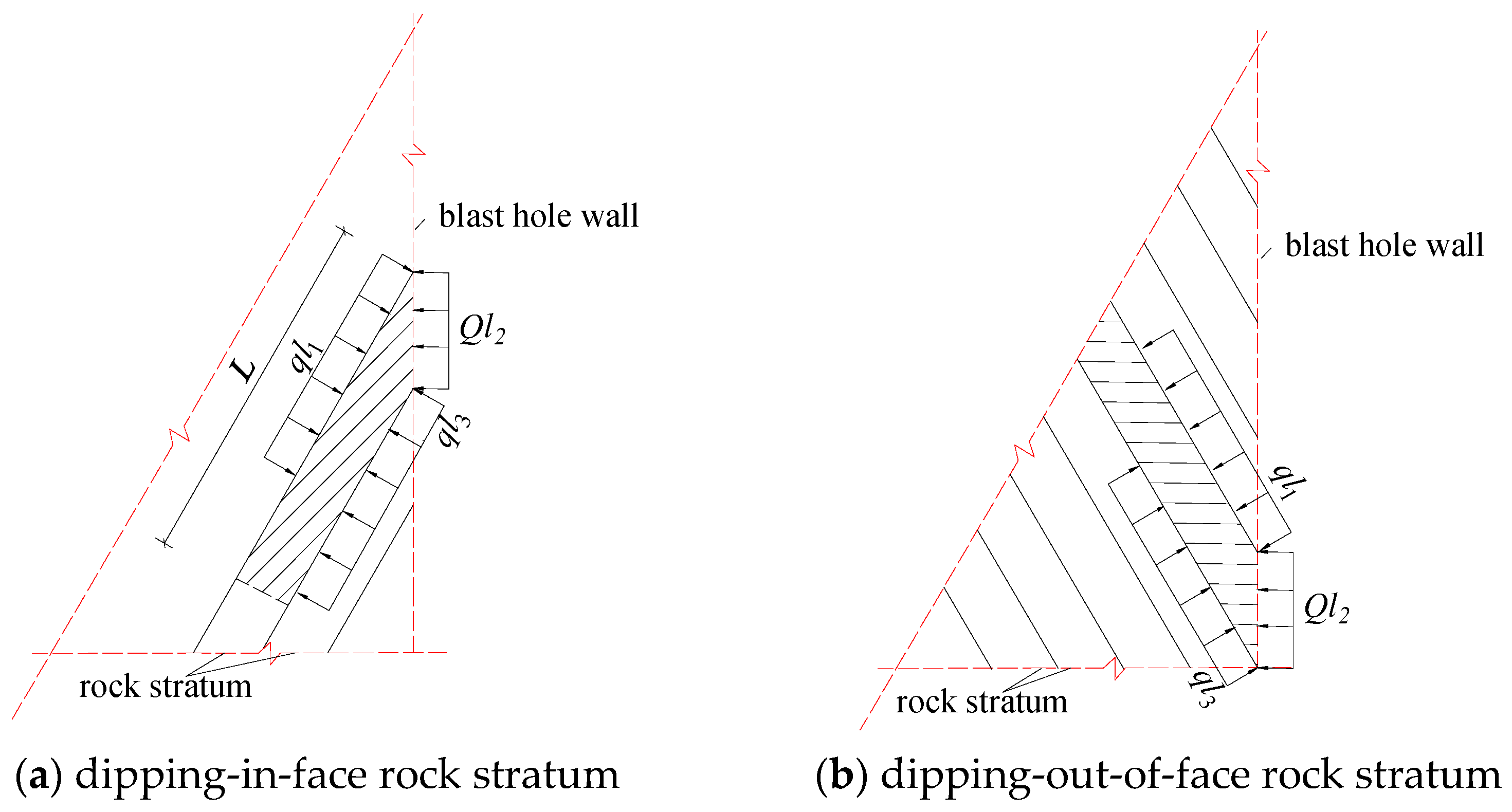
Compared with the blasted rock, the expansion of the blast hole and the incursion of the blast gas are restrained in the remaining rock so the damage range of the remaining rock is reduced. When a bedding plane transects the blast hole, however, the intrusion of explosive gas into the rock mass cannot be ignored. In this paper, combined with actual engineering, a single row blast hole charge structure and a layered rock model diagram was established, as shown in Figure 1. The rock layer inclination was opposite to the free surface, which was a dipping-in-face rock bench; α was the dip angle, “+” meant the dipping-out-of-face rock stratum, “−” meant the dipping-in-face rock stratum and d was the thickness of the stratum.
Due to the structural failure characteristics of a layered rock mass being similar to a bending fracture in different engineering works [16,17], many scholars have applied structural mechanics to analyze the failure laws of layered rock masses [18,19]. The free face at the top of the bench and the new free face after the rock mass is blast-fractured provide the necessary conditions for the structural failure of layered rock mass. As shown in Figure 1, the single stratum was mainly constrained by the adjacent layered rock and the explosive gas might intrude into each bedding plane, so a single stratum might be bent under the pressure of the blasting gas. If the restraint action of the adjacent rock mass was equivalent to the bending stiffness of the single rock mass, the single-layer rock mass could be approximated as a cantilever structure. A simplified stress model of the rock cantilever beam under different inclination conditions was established, as shown in Figure 2. The rock mass behind the blast hole was mainly affected by the explosive gas pressure on the blast hole and intrusive rock surface. l1 and l3 represented the initial depth of the explosive gas intruding into each layer. L was the assumed failure length of the cantilever beam, q and Q were the explosive load values per unit length and the beam width in the Figure was the same as the blast hole spacing.

2.2. Single Degree of Freedom (SDOF) Dynamic Model of a Layered Rock Mass

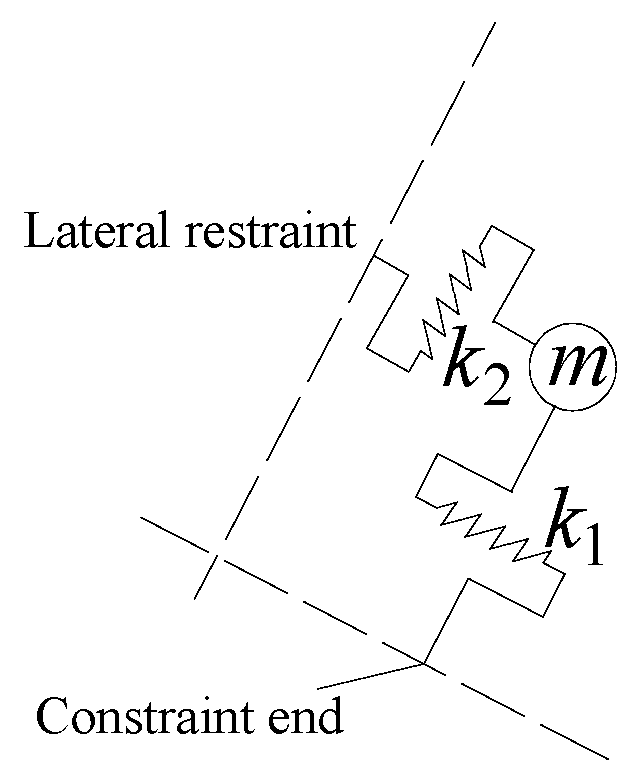
It can be seen from the mechanical conditions of the single-layer rock mass in Figure 2 that the cantilever rock mass had a large structural stiffness under the restraint of the surrounding rock mass and the influence of its own structure. Under the combined force of a strong impact dynamic explosion load, the structure might still have been damaged by bending. Due to the short duration of the explosive load, our analysis established a single degree of freedom (SDOF) structural dynamic model based on the above-mentioned mechanical conditions by using a structural dynamic method as shown in Figure 3.
In the calculation model, the rock cantilever structure was equivalent to a particle m. The geometric size and constraint conditions of the rock mass determined the stiffness characteristics of the beam. In Equation (1), k1 was the bending stiffness and k2 was the tangential stiffness constrained by the surrounding rock. Therefore, the above model needed to satisfy the dynamic equilibrium equation [24]:
m y ¨ + k y = F ( t , α )
where m was the mass of the cantilever beam; k was the total structural stiffness, k = k1 + k2; y ¨ and y were the dynamic acceleration and displacement of the particle m, respectively and F(t, α) was the resultant force along the bending direction, which could be calculated from the explosive load action curve and the dip angle α. From Equation (1), it could be seen that under the dynamic action of the explosive load F(t, α), the energy of the explosion load was mainly converted into kinetic energy, represented by m y ¨ , and deformation energy, represented by ky, which was obviously different from static conditions.
The internal force in the structure should be the difference between the external force and its own inertial force [24] so the shear force F′ acting on the particle m and the bending moment Wl of the constraint section were as follows:
F = F ( t , α ) m y ¨ = k y
W l = F L
where L was the failure length of the single-layer cantilever beam.

2.3. Calculation Parameters and Failure Criteria

2.3.1. Structural Stiffness

The structural stiffness k consisted of two components, the bending stiffness k1 of the beam structure and the tangential stiffness k2 determined by the surrounding rock mass constraints [21]. k1 was calculated as follows [25]:
k 1 = 3 E I / L 3
where L was the failure length of a single-layer cantilever beam, E was the elastic modulus of the material, I was the moment of inertia of the bending section, I = bh3/12. b was the width of the beam and h was the thickness of the rock layer. The tangential stiffness k2 could be determined according to Equation (5) [26]:
k2 = GA/ξL
where G was the rock mass shear modulus, A was the cross sectional area of the surrounding rock affected by the deformation of the cantilever beam structure and ξ was the proportionality coefficient.

2.3.2. Explosion Load

According to the theory of the combined action of the explosion shock wave and explosion generated gas, the retained rock mass near the blast hole was first subjected to the action of the explosion shock wave and its action time was short, at tens of subtle levels. Under the action of the explosion shock wave, the surrounding rock broke to form a broken area and consumed a lot of energy and then attenuated to a stress wave and propagated to a distance. Under the influence of the explosion gas invasion and quasi-static pressure, the rock fracture then continued to develop and the degree of fragmentation continued to increase. Daehnke used PMMA material to study the blasting fracture law under the condition of sealing and packing. It found that 8% of crack propagation was caused by the stress wave and the remaining 92% was caused by gas pressure [27]. The development of cracks weakens the properties of rock mass material and reduces the modulus of rock mass material, as shown in Equations (6) and (7). For pre-existing cracks before blasting, its influence is reflected in the initial material properties of the rock.
G T G = 1 32 45 ( 1 ν ) ( 5 ν ) 2 ν χ
E T E = 1 16 45 ( 1 ν 2 ) ( 10 3 ν ) 2 ν χ
where ET and GT are the equivalent elastic modulus and shear modulus, v is Poisson’s ratio and χ is the fracture density parameter. When χ approaches 1, ET and GT are zero, which indicates the complete failure of the rock mass. After a calculation with the above formula, the maximum attenuation of the elastic modulus and the shear modulus under the influence of the shock was less than 15% of the original value. According to the research results of Esen [28], the failure area formed by the shock wave was within five times of the blast hole radius and the fracture area was within 30 times of the blast hole radius. Therefore, in order to reflect the impact wave on the structural failure of the remaining rock mass, it was approximately considered that the structural stiffness of the rock mass within 30 times of the blast hole radius decreased by 15%.
According to the theory of detonation thermodynamics, the expansion process of the explosive gas in the blast hole is an isentropic adiabatic process. Under the condition of a coupling charge, when the explosive gas fills the blast hole, the blast hole wall pressure P0 is [29]:
P 0 = ρ C 2 2 ( γ + 1 )
where, ρ is the explosive density, C is the explosive velocity and γ is the adiabatic index. The value of the industrial explosives such as emulsion explosive and ammonium nitrate explosive is generally 3. According to the relevant research results, a triangle function is often used to express the equivalent load curve of the explosion load. The peak value of the explosion load is P0 in the t1 period and then linearly attenuates in the t2 period [29,30]. According to the actual observation results of bench blasting and related theoretical studies [20,31], the load action time of bench blasting should be in the order of 10 ms. In this paper, the pressure rise period t1 of the load was 1 ms and the pressure reduction period t2 was 10 ms to reflect the time history of the load. In addition, according to research results [32], under reasonable plugging conditions, the amount of compression of the plugging material in the plugging section was small. Within 10% of the length of the plugging section, in order to reflect the difference between the stemming section and the charge section and considering that some of the plugging materials would be thrown out of the blast hole, the peak value of the loading action of the particle on the stemming section was reduced to 15% of the original value.

2.3.3. Failure Criterion of a Rock Cantilever Beam Structure

According to the failure characteristics of the cantilever beam structure and the characteristics of the rock material, when the bending moment in the beam exceeded the material strength limit, the beam structure underwent an integral bending failure. At that point, the section compressive stress generated by the bending moment caused the rock mass at the restraining end to crush and fail. The corresponding critical failure conditions were:
[ σ ] = σ c max
where [σ] was the value of the rock dynamic compressive strength and σcmax was the maximum bending compressive stress at the restrained end of the beam. According to the calculation method of the internal force under a pure bending condition, the following formula could be used for the calculation [33]:
σ c max = | W l | d 2 I
where d was the section height, which corresponded to the thickness of the rock layer, Wl was the bending moment and I was the moment of inertia.
In addition, for the structure of the bedding slope, there was a sliding tension crack failure along the bedding direction and the critical failure condition was [34]:
F T = F C tan φ + c T L T
In the formula, FT and FC were the combined external forces along the tangential and normal directions of the bedding plane per unit width, CT and φ were the cohesive force and internal friction angle of the bedding plane of the rock mass and LT was the length of the slip plane.

3. Influence of a Thin Stratum on the Forming Effect of a Free Surface after Blasting

3.1. Calculation Pressure Length of Explosive Gas on a Rock Layer

Due to the complex explosion mechanism, it is difficult for existing methods to accurately determine the process of explosive gas intrusion into the bedding plane of layered rock and it is also difficult to obtain the pressure value on the bedding plane. Many scholars have approximately treated the pressure value of explosive gas between the pores and approximately considered that the explosive gas has a stress effect in the whole fracture and its value is consistent with the pressure value in the blast hole [35]. In this way, the calculation results can also meet the engineering accuracy. To achieve a structural dynamic analysis, the following assumptions were made to simplify the analysis process: (1) after the explosive gas intruded into the bedding plane, the pressure value on the surface was still the same as the load pressure value of the hole wall; (2) the maximum fracture length along the bedding plane under the action of the hole wall load was taken as the calculation pressure length of the explosive gas on the rock layer.
According to Duhamel’s integral principle of structural dynamic response under a general load [24], the deformation displacement value y’ of a single degree of freedom structure under the impulse S can be calculated by:
y’ = S/
S = T 1 T 1 + Δ t F ( t , α ) d t
where ∆t is the failure time, ω is the frequency parameter of the structure and ω = k / m . Figure 1 showed that the distance between the cantilever beam at different positions and the top free surface was different and the tangential stiffness k2 was obviously different. Under the same load condition, the dynamic response of different parts of the cantilever structure was different. For this reason, from the perspective of structural deformation, the maximum fracture aperture K of the bedding joint could be determined from the maximum bending deformation difference between two adjacent rock layers. Combining Formulas (4), (8), (11) and (12), the maximum opening K of the layer joint appearing at the hole wall could be derived from:
K = Δ ( 1 m ω ) 0 t F p ( t ) | sin α | d t
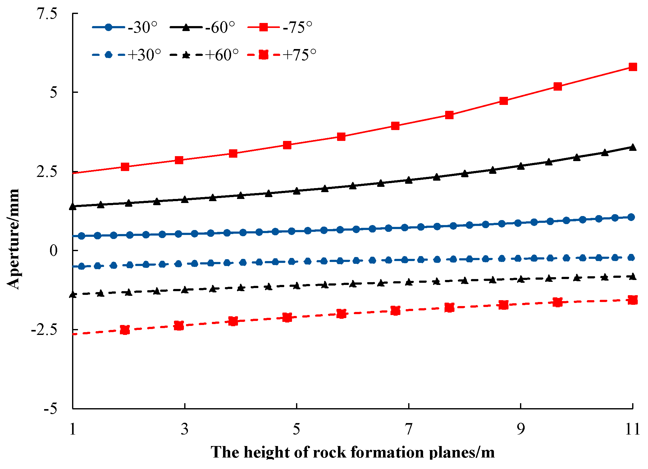
where t was the load period and Δ(1/) was the difference of 1/ of the adjacent rock strata. As shown in Table 1, it is the calculation parameters of the cantilever beam structure dynamic model of the layered bench rock mass in which the layered joints were closed cemented joints. In practical engineering, the joint surface will reduce the strength and stiffness of the rock mass. According to the research results of Zhao [36], the stiffness parameter of the rock mass at the joint surface was taken as 10−2 times of the original value and the strength parameter was taken as 0.5 times so as to approximately reflect the mechanical properties of the plane joints. Figure 4 shows the variation of joint opening under different dip angles calculated by Equation (13). The abscissa in Figure 4 represented the height of the interface between the bedding plane and the hole wall.
Under the conditions of rock strata with different dip angles, the fracture aperture of the bedding plane showed opposite changes. The fracture aperture of dipping-in-face strata gradually increased with the increase of the height of the bedding plane. The larger the inclination angle of the layered rock, the larger the changes of the fracture aperture. This indicated that the structural bending characteristics of the dipping-in-face strata were stronger. Under the action of the explosion load pressure, the cracking trend of the bedding planes in the dipping-in-face strata was more obvious. In the consequent bedded rock, the fracture aperture decreased with the increase of the height and the decrease of the inclination angle and changed little. In addition, other research has shown that there is a certain correlation between the crack length and the fracture aperture in the tensile deformation cracking characteristics of different materials [37]; the quantitative relationship between the crack opening and the theoretical development length has been established as:
K = a L β
where L is the theoretical crack length; β is the characteristic index with a value range of 0.5–2.0 and a is the relevant parameter, which is determined by the crack initiation and propagation conditions and can be obtained through experiments. In our model, the relevant parameters were fitted according to the numerical simulation results; the results are shown in Table 1. Combining Equations (13) and (14), the initial penetration length l1 and l2 in the cantilever beam structure calculation model could be determined.

3.2. The Damage Range of the Structural Model

Based on the above model and failure criterion of the cantilever beam structure, the above-mentioned failure length L of the cantilever beam structure could be calculated by the following formula:
3 E I L 4 + G A ξ L 2 = [ σ c ] ρ ( b h ) 2 6 T 1 T 1 + Δ t F ( t , α ) d t
where T1 was the initial failure time of the load, ∆t was the duration of the load failure and ρ was the rock mass density while other parameters remained the same as before. The failure length of the cantilever beam structure model was related to the rock inclination, load value and its failure time. From the perspective of the cantilever beam structure failure, the bending failure time of the constrained end of the cantilever beam should have been the same as the time of the tensile crack penetrating the beam section caused by tensile stress. Thus, the failure time was calculated approximately according to the following formula [38]:
Δ t = h / v ¯
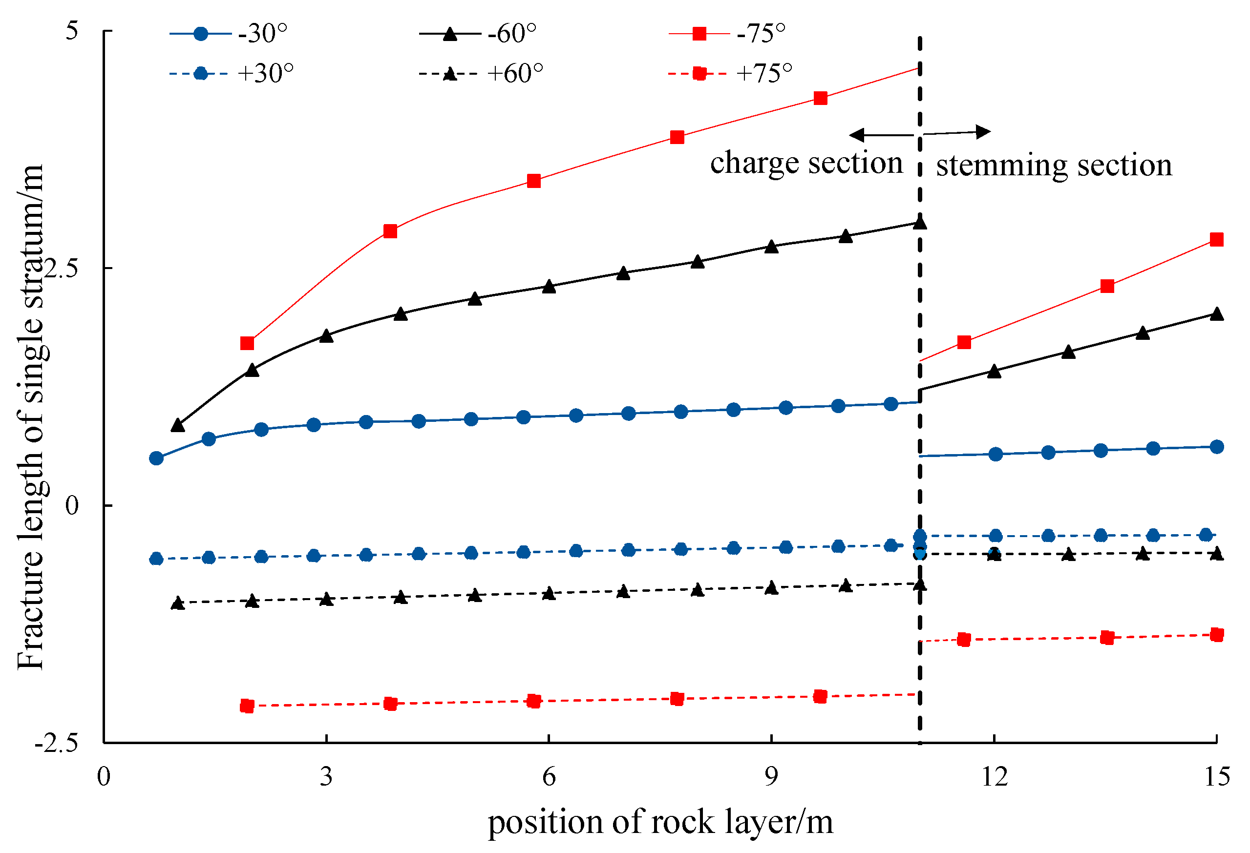
According to the Griffith theory, the crack growth rate v ¯ = 0.38Cp and Cp is the longitudinal wave velocity of the rock [38]. Figure 5 shows the calculation results of the maximum failure length of the rock structure at each height under different inclination conditions.
Figure 5 shows that the failure length of the cantilever beam in the dipping-in-face stratum was larger than in dipping-out-of-face stratum. With the increase of the height and dip angle, the failure length of the dipping-in-face stratum increased significantly and the maximum value reached 5.2 m while the failure length of the dipping-out-of-face stratum was uniform; for example, in + 75° stratum, it was about 2.5 m. The above results indicate that the bending failure characteristics were obviously stronger in the dipping-in-face stratum.
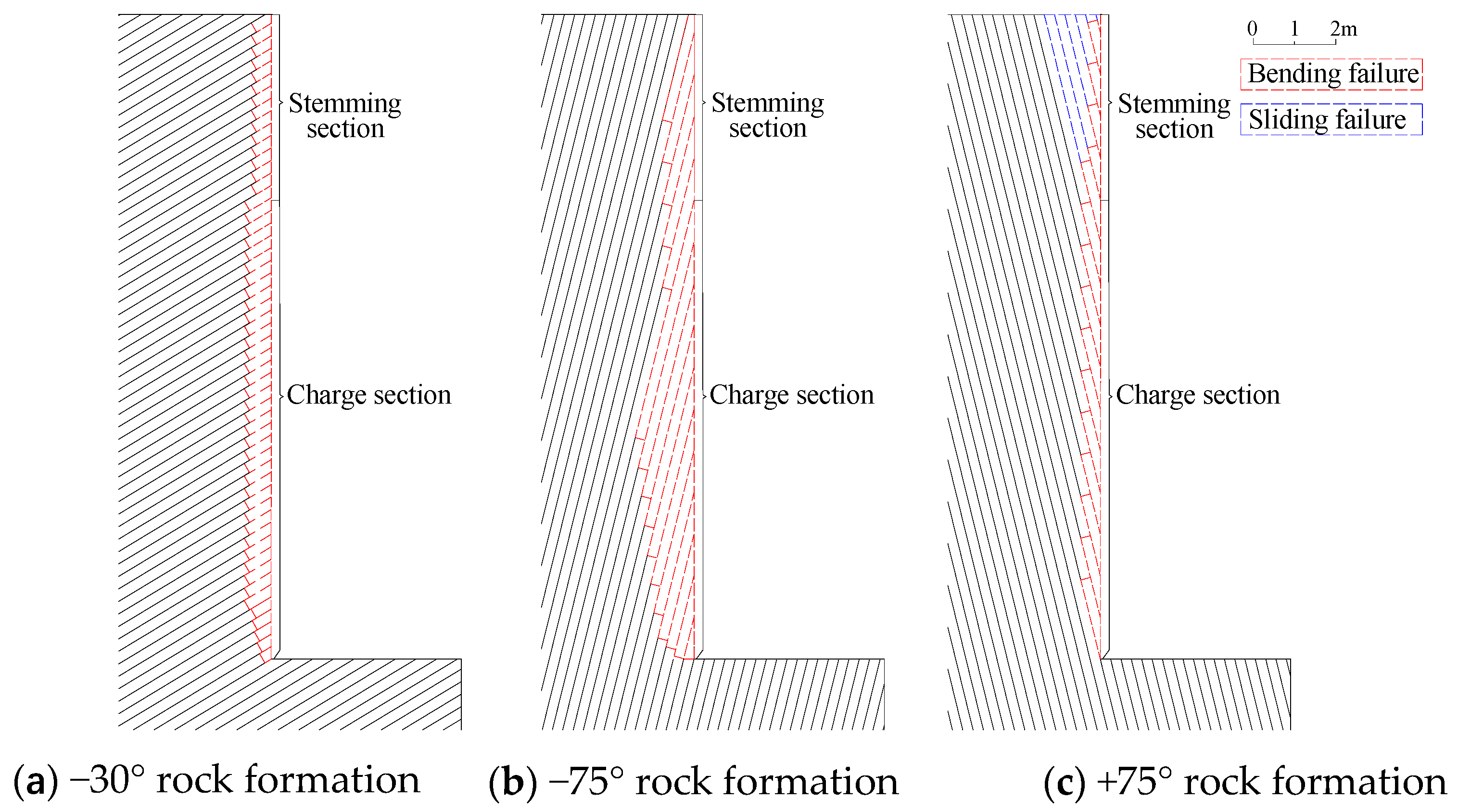
Therefore, based on the above calculation results, the diagram of the failure range of the remaining rock mass under different dip angles was drawn, as shown in Figure 6. According to the calculation results, under the same load conditions, the free surface of the dipping-out-of-face stratum and gently inclined rock was relatively flat after blasting and the failure depth was about 0.5 m. In the dipping-in-face rock, with the increase of the dip angle, the failure trend of the rock along the plane increased obviously, resulting in the failure depth of the bottom rock being larger than that of the top rock, forming an inverted ridge failure pattern along the plane. The maximum failure depth of the charging section was about 1.9 m and the average failure depth at the top of the step was about 0.9 m. It was not conducive to the next bench blasting operation. In addition, with the increase of the dip angle in the dipping-out-of-face strata, the top rock mass was prone to a slip tensile fracture failure along the bedding plane, as shown in Figure 6c, which made the failure depth of the top rock mass larger than that of the lower rock mass. It could be seen that the failure characteristics of the strata with different dip angles were different.

4. Comparison of Numerical Simulations

4.1. Simplified Structural Mechanical Model

A new discrete element analysis software, named as GDEM [39], was used to simulate the fracture law of the retained rock mass. Based on the continuous-discontinuous element theory (CDEM) [36], this software realized the discrete analysis of rock fragmentation, structural plane failure and fracture development under blasting load. It can also simulate the elastic-plastic deformation of materials and the initiation, expansion and penetration process of explicit cracks in materials.
As shown in Figure 7, the plane analysis model of the same size of bench was established based on Figure 1. The main analysis object was the remaining rock; the thickness of the single stratum was 0.2 m and the dip angle was −75°. In the calculation model, the left, bottom and right boundaries were non-reflective and fixed. The joints analyzed in the model were closed, cemented and unfilled joints. The contact relationship between the element blocks in the model was face-to-face contact [39]. It was controlled by several parameters such as normal stiffness, stress stiffness, friction angle and cohesion. When the internal force of the contact surface exceeded the failure criterion, the contact surface fractured so as to realize the discrete element analysis. The rock mass units at the joints were also connected by a face-to-face contact but, according to the research results of Zhao [36], the stiffness parameter of the rock mass at the joint surface was taken as 10−2 times of the original value and the strength parameter was taken as 0.5 times so as to approximately reflect the mechanical properties of the plane joint.
The fracture law of the retained rock mass under six dip angles of ± 30°, ± 60° and ± 75° was analyzed. The material parameters of the rock mass were determined according to Table 1. The specific values are shown in Table 1. In the calculation model, the influence of the blasted rock mass between the blast hole and the free face was not considered. As shown in Figure 7, the equivalent load force was applied in the form of surface force at the boundary of the charging section and 0.2 times of the equivalent load force was applied to the hole wall of the plugging section. The failure mechanism was analyzed by the dynamic analysis method. When the explosion gas invasion was considered, the bidirectional load pressure was also applied at the joints of the layer. The time of the load rise and drop and the peak value of the load action were consistent with the above model. The starting time of the load at the body was determined according to the time of the detonation wave propagating from the initiation point to this place so as to simulate the bottom initiation and the uniformly distributed load force q was applied at the hole wall and some rock surfaces.

4.2. Result Analysis

4.2.1. The Influence of the Dip Angle on the Development of Bedding Joints

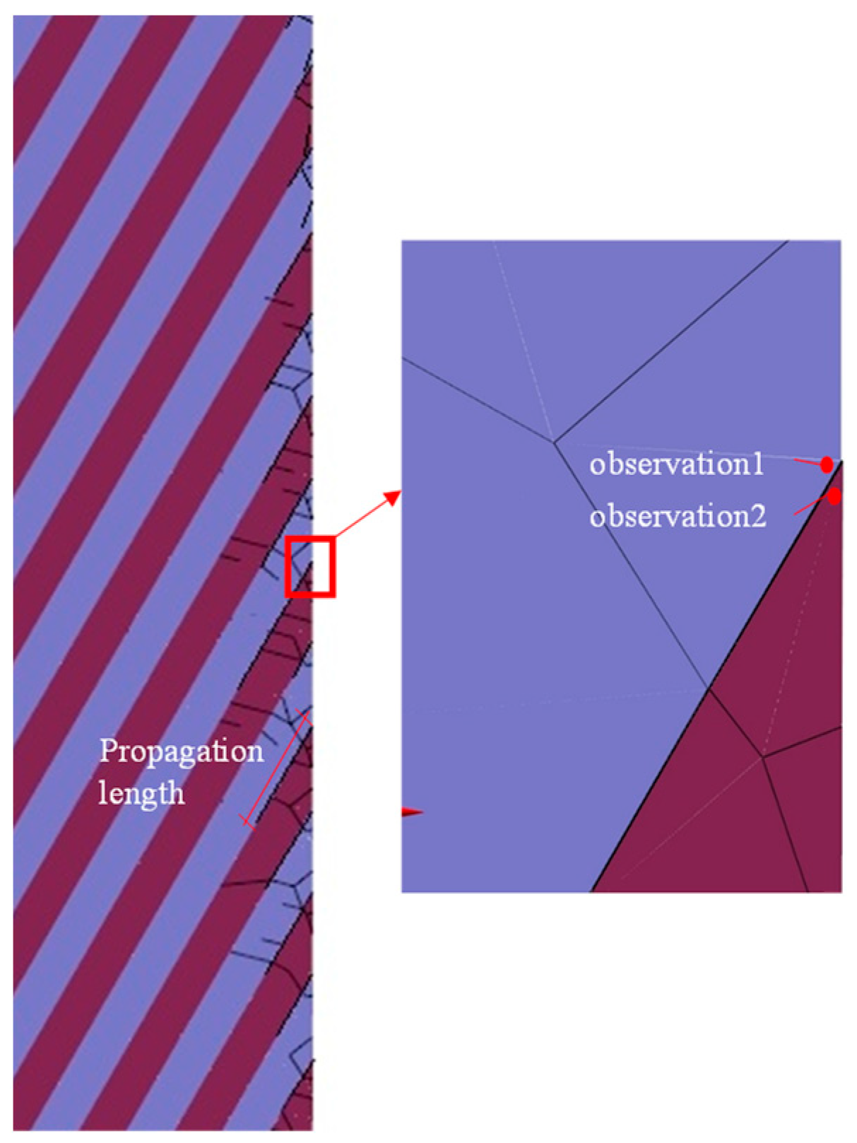
Based on the above theoretical analysis method, the invasion process of explosion gas mainly occurred in the loading period. After the explosion load was applied to the hole wall, the crack propagation law was obviously different under the condition of the different dip angle. Figure 8 shows the fracture propagation of a rock stratum with an inclination of −75°. The adjacent rock strata in the Figure are shown in different colors and the black line represents the fracture boundary line and fracture condition between the blocks.
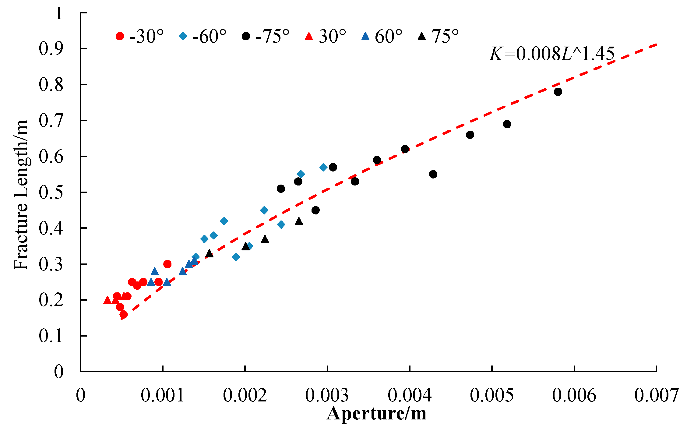
According to the theory of the continuous-discontinuous element method (CDEM), cracks are formed when a contact fracture occurs between rock elements. The black line in Figure 8 indicates the fracture boundary line and cracking condition between the blocks. Rock cracks developed along the bedding joints and also along the direction perpendicular to the rock bedding but the development length along the bedding cracks was greater. The maximum propagation length of cracks along the bedding plane at different of the bench was recorded, which was approximately taken as the action length of the explosion gas in the cantilever beam model. To verify the quantitative relationship between the opening of the bedding plane and the crack length in the model, the values of the two parameters at different inclination angles from ± 30° to ± 75° were calculated and compared, as shown in Figure 9. According to Equation (15), the quantitative relationship between the crack opening and the crack length suitable for a bench blasting analysis of the layered rock mass was calculated, which was applied in the theoretical structural dynamics model. The relevant results are shown in Table 1 and Figure 9.

4.2.2. Influence of Rock Dip Condition on the Failure Range of the Remaining Rock

To determine the influence of the rock dip condition on the failure range of the remaining rock, the Mohr-Coulomb model and the maximum tensile stress model were used to describe the tensile, compressive and shear failures of the element under the explosion load [39] and the damage coefficient in the model was used to reflect the failure degree of the element. As shown in Figure 10, the damage coefficient represented the degree of cracking failure and the damage of the element interface. The value of 1 represented a complete failure. The results shown in Figure 10 indicated that the failure law of the rock mass was obviously different under different inclination conditions. Under the condition of the dipping-out-of-face rock stratum, the failure depth of the remaining rock changed little along the height direction. With the increase of dip angle, the failure depth of the top rock mass increased obviously, as shown in Figure 10c. The reason was that the top free face had less constraint on the rock stratum and the rock mass had an obvious failure trend along the bedding plane. In dipping-in-face rock stratum, when dip angle was small, the change of rock failure depth was not obvious; the average failure depth was basically within 0.6 m as shown in Figure 10a. With the increase of the dip angle, the failure depth of the bottom rock mass was significantly greater than that of the top rock mass. Combined with the structural dynamic analysis results, the main reasons for the failure mode were that under the action of the explosion load, the dynamic effect of the top layer structure was obvious and the bending failure depth was large and the rock failure developed towards the bottom. The numerical simulation results were in good agreement with the theoretical calculation and the failure shape of the rock mass was similar.

5. Engineering Measurements and Discussion

5.1. Project Overview

The Changjiu (Shenshan) limestone mine is located approximately 37 km southwest of Chizhou. The mining area is approximately 4.73 km2 and contains 1.921 billion tons of limestone for cement and aggregates for ordinary building. The designed mining scale is 70 million tons/year and the mining scale and open aggregate processing scale of limestone will become the first in the world in the future. The limestone rock mass of the mine is shallow and most easily accommodated by an open-pit bench blasting method. The average bench height of the region is approximately 10–20 m. The mining area is dominated by mainly limestone deposits. In the northern mining area of the project, there is a large range of layered rock mass; the average thickness of the layered rock is about 0.20 m and the dip angle of the rock stratum is about 70°–75°. The strike of the rock strata is consistent. With the bench blasting advancing in different directions, the bench of the dipping-out-of-face stratum and the dipping-in-face stratum is gradually formed. The physical and mechanical parameters of the rock mass in the project are shown in Table 1 and the test parameters of bench blasting are shown in Table 2. According to the actual situation of the site, the shape of the remaining rock mass after each blasting was quantitatively measured by using a laser scanner, FARO 3D.

5.2. Measured Results and Analysis

5.2.1. Failure Characteristic Analysis

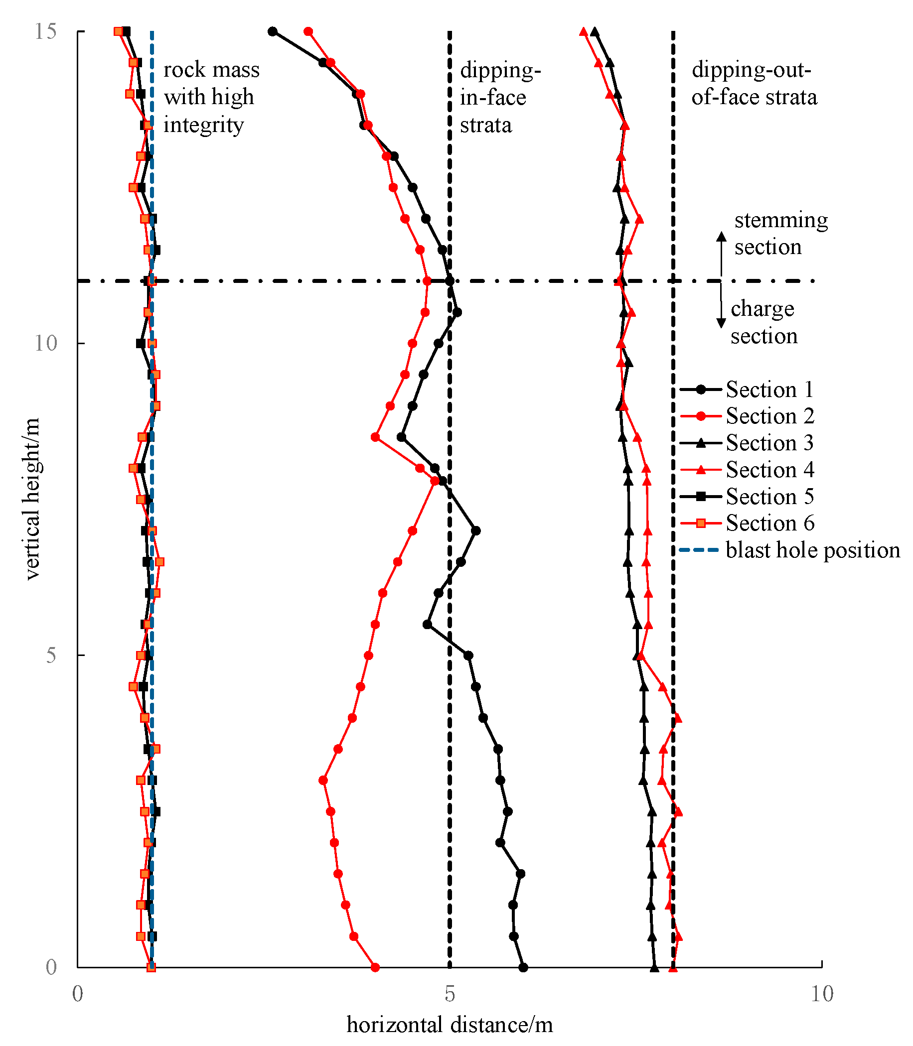
Figure 11 shows the actual failure morphological characteristics of the remaining rock characterized by different dipping strata after bench blasting. After processing the captured image data, the profile morphological maps of the new free surface at different sections were drawn. The results are shown in Figure 12 in which sections 1, 3 and 5 are the sections at the blast holes and sections 2, 4 and 6 are the sections of the rock mass between boreholes. The measured results show that the shape of the free face changed greatly in the dipping-in-face stratum. The maximum failure depth at the bottom was about 1.7 m while the average failure depth at the top was 0.8 m, forming an unfavorable shape. The newly exposed surface of the rock stratum and the failure plane perpendicular to the rock bedding plane can be observed in Figure 11a. The actual observation results showed that the failure characteristics of the dipping-in-face strata were similar to the bending failure characteristics of the cantilever structures.
In contrast, the new free surface was relatively flat under the condition of the dipping-out-of-face stratum and without stratum and the free face was basically parallel to the blast hole axis. The residual blast hole traces could be observed in the rock without stratum, as shown in Figure 11c. It could be seen that the failure characteristics of the rock structure were smaller under the condition of a more complete lithology and the material properties of the rock mass had a greater impact on the failure range. In addition, under the condition of the reverse dip strata, the morphological characteristics of the rock mass between the holes changed obviously and the bottom rock mass appeared. From the perspective of structural dynamics, the dynamic failure characteristics of the rock mass at the bottom of the bench were weak and the intrusion range of the explosive gas was limited, which made the rock mass at the bottom between the two holes more difficult to be damaged. The morphological characteristics of the free surface at the blast holes in the measured results were basically consistent with the results obtained by the cantilever beam model. It verified the feasibility of this method for predicting the back-break of layered rock.

5.2.2. Control Measures of the Free Surface Shape

The shape of the free face was the most irregular after blasting in the steep and dipping-in-face strata, which can easily affect the blasting effect of the next blast cycle. From the perspective of the rock structure failure characteristics, the following measures should be taken to optimize the blasting design on the premise of ensuring the blasting effect of the blasted rock mass: (1) the failure shape of the rock mass between the blast holes is obviously different from that at blast holes as the damage range of a single hole is limited. To reduce the damage range of the rock mass at the blast hole, the drilling density coefficient should be increased and the drilling and blasting parameters of small hole diameter and small hole spacing should be adopted. (2) From the above calculation results, the larger the dip angle is, the smaller the angle between the strata and the blast hole and the more obvious the structural failure characteristics of the rock mass are. Therefore, applying the inclined blast hole can change the stress direction of the rock stratum, reduce its structural failure characteristics and control the formation of post tension.

6. Conclusions

The main conclusions are as follows:
(1) Based on the theory of structural dynamics, a simplified stress model of a layered rock mass structure was established. By using the single degree of freedom dynamic analysis method, the stress characteristics of the rock mass behind the blast hole were analyzed and the failure law of the rock mass behind the blast hole was analyzed from the perspective of structural dynamics.
(2) Combined with the CDEM numerical calculation method, the dynamic response characteristics of the structure were obviously different in variably dipping strata. With an increase in the dip angle and height, the length of the bending failure increased and the maximum value was 5.2 m. The theoretical and numerical results showed that with an increase in dip angle, the structural failure characteristics of the rock mass along the bottom of the strata were more obvious, resulting in the failure depth of the rock mass at the bottom of the blast hole being greater than that at the top, forming an unfavorable inverted sill shape. The failure depth of the dipping-out-of-face and gently inclined strata was relatively uniform at about 0.5 m.
(3) Based on a bench blasting test in the Changjiu (Shenshan) limestone mine, the analysis of the shape characteristics of the new free surfaces in variably dipping strata under the same initial conditions showed that reverse dip strata free surfaces are the most irregular after an explosion. The maximum failure depth at the blast holes was about 1.7 m while the average failure depth at the top was 0.8 m and damage characteristics of the fracture occurred along the bedding plane. This was consistent with the theoretical analysis and numerical calculation results. This verified the feasibility of the above method in predicting back-break. From a dynamic point of view, a control method of the free surface shape after blasting in a reversed-dipping layered rock mass was proposed.

Author Contributions

Conceptualization, M.C.; data curation, D.W.; methodology, W.L.; formal analysis: D.W. and M.C.; investigation, Z.W.; writing-original draft preparation, M.C.; writing visualization, D.W. All authors have read and agreed to the published version of the manuscript.

Funding

This research was funded by National Natural Science Foundation of China (Grant No. 51979205, No. 51779193).

Informed Consent Statement

Not applicable.

Conflicts of Interest

The authors declare no conflict of interest.

References

  1. Faramarzi, F.; Farsangi, M.A.E.; Mansouri, H. An RES-Based Model for Risk Assessment and Prediction of Backbreak in Bench Blasting. Rock Mech. Rock Eng. 2013, 46, 877–887. [Google Scholar] [CrossRef]
  2. Trivedi, R.; Singh, T.N.; Gupta, N. Prediction of Blast-Induced Flyrock in Opencast Mines Using ANN and ANFIS. Geotech. Geol. Eng. 2015, 33, 875–891. [Google Scholar] [CrossRef]
  3. Chuang, H.E.; Dongmei, Y.I.N. Analysis of Influence of Free Surface and Minimum Resistance Line on Blasting Vibration. Tunn. Constr. 2018, 1, 1–6. [Google Scholar]
  4. Singh, P.K.; Roy, M.P.; Sinha, A. Causes of toe formation at dragline bench and its remedial measures. Rock Fragm. Blasting 2012, 11, 187–192. [Google Scholar]
  5. Xiao, Z.X.; Guo, X.B.; Zhang, J.C.; Pu, C.J.; Xiao, D.J.; Xia, Z.K. Numerical simulation and test of lamination effect caused by blasting in layered rock slope with weak intercalated layer. Rock Soil Mech. 2009, 30, 31–34. (In Chinese) [Google Scholar]
  6. Ma, L.; Lai, X.; Zhang, J.; Xiao, S.; Zhang, L.; Tu, Y. Blast-Casting Mechanism and Parameter Optimization of a Benched Deep-Hole in an Opencast Coal Mine. Shock Vib. 2020, 33, 875–891. [Google Scholar] [CrossRef]
  7. Taliercio, A. A failure conditions for layered rock. Rock Mech. Min. Sci. 1988, 25, 299–305. [Google Scholar] [CrossRef]
  8. Sacchi, G.; Taliercio, A. A Note on Failure Condition for Layered Materials Mechanics. J. Meccanica 1987, 22, 97–102. [Google Scholar] [CrossRef]
  9. Bayly, B. Deformability of Layred of Jointed Rock Masses. Analysis and Comparison of different Typesof Test. Rock Mech. Min. Sci. 1982, 19, 195–199. [Google Scholar] [CrossRef]
  10. Ash, R.L. Influence of Geological Discontinuities on Rock Blasting. Ph.D. Thesis, Ph D Symp on rock mechanics, University of Minnesota, New York, NY, USA, 1973; pp. 263–271. [Google Scholar]
  11. Ash, R.L.; Konya, C.J. Flexible Sprengung—Eine Neue Theorie uber Fellsprengung. Proc. Informationstag für Sprentechnik; Wirtschaftsforderunginstitut: Linz, Austria, 1975; Volume 11, pp. 13–24. [Google Scholar]
  12. Barker, D.B.; Fourney, W.L.; Holloway, D.C. Photoelastic investigation of flan initiated cracks and their contribution to the mechanism of fragmentation. In Proceedings of the 20th US Symposium on Rock Mechanics (USRMS), Austin, TX, USA, June 1979; pp. 119–128. [Google Scholar]
  13. Wang, M.Y.; Qian, Q.H. Attenuation law of explosive wave propagation in cracks. Chin. J. Geotech. Eng. 1995, 17, 42–46. (In Chinese) [Google Scholar]
  14. Zhu, J.B.; Zhao, J. Obliquely incident wave propagation across rock joints with virtual wave source method. J. Appl. Geophys. 2013, 88, 23–30. [Google Scholar] [CrossRef]
  15. Zhu, J.B.; Zhao, X.B.; Wu, W.; Zhao, J. Wave propagation across rockjoints filled with visco elastic medium using modified recursive method. J. Appl. Geophys. 2012, 86, 82–87. [Google Scholar] [CrossRef] [Green Version]
  16. Jiang, L.W.; Huang, R.Q. Bending yielding and tensile cracking critera for failure of rock slope whose dip direction opposite to the dip direction of strata. J. Eng. Geol. 2006, 14, 289–294. (In Chinese) [Google Scholar]
  17. Xiao, Y.; Wang, S. A Study on the Flexural Breaking of Rockmass; Mechanics of Jointed and Faulted Rock: Rotterdam, The Netherlands, 1990. [Google Scholar]
  18. Liang, Y.P.; Sun, D.L. Study on the composed rock beam theory of strata movement and its application. J. Rock Mech. Eng. 2002, 5, 654–657. [Google Scholar]
  19. Mandal, S.K.; Dasgupta, M.M.S. Theoretical concept to understand plan and design smooth blasting pattern. Geotech. Geol. Eng. 2008, 26, 399–416. [Google Scholar] [CrossRef]
  20. Hasanipanah, M.; Shahnazar, A.; Arab, H.; Golzar, S.B.; Amiri, M. Developing a new hybrid -AI model to predict blast-induced back-break. Eng. Comput. 2017, 33, 349–359. [Google Scholar] [CrossRef]
  21. Ebrahimi, E.; Monjezi, M.; Khalesi, M.R.; Armaghani, D.J. Prediction and optimization of back-break and rock fragmentation using an artificial neural network and a bee colony algorithm. Bull. Eng. Geol. Environ. 2016, 75, 27–36. [Google Scholar] [CrossRef]
  22. Liu, J.; Wang, S.R.; Gao, Q.C. Numerical simulation of rock remain damage characteristics under single hole bench blast. Explos. Shock Waves 2003, 23, 241–247. [Google Scholar]
  23. Dey, A.; Gupta, R.N.; Ghose, A.K. Blast evaluation using high speed video camera: A case study in Jharia coalfield. J. Mines Met. Fuels 1999, 47, 31–35. [Google Scholar]
  24. Jiang, L.; Zeng, J.; Wang, G. A discrete dynamic response model with multiple degrees of freedom for horizontal goaf group. J. Rock Mech. Eng. 2016, 35, 59–67. (In Chinese) [Google Scholar]
  25. Tileylioglu, S.; Stewart, J.P.; Nigbor, R.L. Dynamic stiffness and damping of a shallow foundation from forced vibration of a field test structure. J. Geotech. Geoenviron. Eng. 2011, 137, 344–353. [Google Scholar] [CrossRef] [Green Version]
  26. Nielsen, A.H. On the use of Rayleigh damping for seismic analysis. Proc. Inst. Civ. Eng. Eng. Comput. Mech. 2009, 162, 215–220. [Google Scholar] [CrossRef]
  27. Daehnke, A. Blast-Induced Dynamic Fracture Propagation. In Proceedings of the 5th International Symposium on Rock Fragmentation by Blasting-FRAGBLAST-5, Montreal, Canada, 25–29 August 1996; pp. 619–626. [Google Scholar]
  28. Esen, S.; Onederra, I. Modelling the size of the crushed zone around a blasting hole. Int. J. Rock Mech. Min. Sci. 2003, 40, 485–495. [Google Scholar] [CrossRef]
  29. Liu, Y.C.; Wang, X.G.; Liu, L.S.; Dou, J.L. An energy method for calculate borehole pressure under decoupled charging. China Min. Mag. 2011, 18, 104–107. [Google Scholar]
  30. Ming, C.; Tao, L.; Zhiwei, Y.; Wenbo, L.; Peng, Y. Calculation methods for peak pressure on borehole wall of contour blasting. Explos. Shock Waves 2019, 39, 103–112. (In Chinese) [Google Scholar]
  31. Yilmaz, O.; Unlu, T. Three-dimensional numerical rock dam-age analysis under blasting load. Tunn. Undergr. Space Technol. 2013, 38, 266–278. [Google Scholar] [CrossRef]
  32. Liu, B.C. Study on Hole Stemming Theory of One-Step Deep Hole Raise Blasting and Its Application; Central South of University: Changsha, China, 2014. [Google Scholar]
  33. Hsu, C.T.T. T-shaped reinforced concrete members under biaxial bending and axial compression. Struct. J. 1989, 86, 460–468. [Google Scholar]
  34. Lu, W.; Bai, B.; Chen, C.X. Analysis of mechanism of plane sliding failure for bedded rock slopes. Rock Soil Mech. 2011, 32, 204–207. [Google Scholar]
  35. Wenbo, L. A study of fracture propagation velocity driven by gases of explosion products. Explos. Shock Waves 1994, 3, 264–268. [Google Scholar]
  36. Feng, C.; Guo, R.K. Effect of joints on blasting and stress wave propagation. J. Rock Mech. Eng. 2018, 37, 2027–2036. (In Chinese) [Google Scholar]
  37. Huang, F.; Yao, C.; Zhou, C.; Yang, J. Numerical simulation and seepage analysis of stochastic fracture network considering correlation between fracture trace length and aperture. Hydro Sci. Eng. 2018, 2, 35–42. (In Chinese) [Google Scholar]
  38. Feng, C.; Li, S.H.; Hao, W.H.; Ge, W. Numerical simulation for penetrating and blasting process of EPW based on CDEM. J. Vib. Shock 2017, 36, 11–18. (In Chinese) [Google Scholar]
  39. Pan, P.F.; Sun, H.G.; Han, Z.; Feng, C.; Guo, R.; Li, S. Numerical Study on Damage and Fracture Degree of Rock Mass induced by blasting mining. Met. Mine 2016, 6, 1–7. [Google Scholar]
Figure 1. Different sectional view of bench blasting in the dipping-in-face rock stratum.
Applsci 11 02577 g001
Figure 2. Schematic diagram of the force model of the cantilever beam structure of the layered rock mass with different dipping direction.
Applsci 11 02577 g002
Figure 3. Dynamic model diagram of a single degree of freedom structure of a reverse dip rock.
Applsci 11 02577 g003
Figure 4. The calculation results of the aperture of the rock joints at different heights of the bench.
Applsci 11 02577 g004
Figure 5. The law of maximum failure length of the rock cantilever beam structure under different conditions.
Applsci 11 02577 g005
Figure 6. Diagram of the over-break sequence of the free surface in layered rock with different dip angles.
Applsci 11 02577 g006
Figure 7. Numerical calculation model of the rock mass behind the borehole under the condition of −75° rock stratum.
Applsci 11 02577 g007
Figure 8. Schematic diagram of the initial fracture and length propagation in a −75° rock stratum.
Applsci 11 02577 g008
Figure 9. Fitting diagram of aperture of fracture along the bedding plane.
Applsci 11 02577 g009
Figure 10. Fracture range and fracture development of the rock mass behind the borehole under different rock dip conditions.
Applsci 11 02577 g010
Figure 11. Failure patterns of the free face after blasting under different kinds of layered rock.
Applsci 11 02577 g011
Figure 12. The shape of the free face after blasting in different inclined strata.
Applsci 11 02577 g012
Table 1. Mechanical parameters of rock mass materials and model calculation parameters.
Thickness of Stratum
/m
Height of Rock Bench/mElastic
Modulus/GPa
Shear
Modulus/Gpa
Cohesion/MPaCompressive Strength/MPaTensile Strength/MPaRock
Density (Kg/m3)
0.215.024.010.01.864.98.52680
Friction
angle
Explosive density ρ (g/cm3)Explosive detonation velocity C (m/s)Characteristic index βRelevant parameter aLongitudinal wave velocity Cp (m/s)Normal stiffness
(GPa/m)
Shear stiffness (GPa/m)
40°0.8529501.450.008350050005000
Table 2. Blasting parameters of the field test.
Test
Sequence
StrataInitiation ConditionsBench
Heigh/m
Hole Diameter/mmDensity CoefficientHole Spacing/mRow Spacing/mStemming/mUnit Consumption (Kg/m3)
1dipping-out-of-face stratumbottom initiation15.01401.556.24.040.41
214.01401.506.64.440.40
3dipping-in-face stratum15.01401.546.34.140.41
414.01401.506.54.340.40
5without stratum15.01401.506.44.240.40
Publisher’s Note: MDPI stays neutral with regard to jurisdictional claims in published maps and institutional affiliations.