Article

Analysis of Injected Electron Beam Propagation in a Planar Crossed-Field Gap

1
Department of Electrical and Computer Engineering, Boise State University, Boise, ID 83725, USA
2
School of Nuclear Engineering, Purdue University, West Lafayette, IN 47906, USA
3
School of Electrical and Computer Engineering, Purdue University, West Lafayette, IN 47907, USA
4
Department of Agricultural and Biological Engineering, Purdue University, West Lafayette, IN 47907, USA
*
Author to whom correspondence should be addressed.
Appl. Sci. 2021, 11(6), 2540; https://doi.org/10.3390/app11062540
Submission received: 12 February 2021 / Revised: 28 February 2021 / Accepted: 9 March 2021 / Published: 12 March 2021
(This article belongs to the Section Electrical, Electronics and Communications Engineering)

Abstract

:
This paper examines basic crossed-field device physics in a planar configuration, specifically electron beam perturbation and instability as a function of variation in magnetic field, and angle between magnetic and electric field. We perform a three-dimensional (3-D) simulation of electron perturbation in a planar crossed-field system using the full 3-D particle trajectory solver in CST Particle Studio (CST-PS). The structure has a length, height, width and anode-sole gap of 15 cm, 2 cm, 10 cm, and 2 cm, respectively. The anode to sole voltage is fixed at 3 kV, and the magnetic field and injected current varied from 0.01 T to 0.05 T and 1.5 mA to 1 A, respectively. The simulations show that applying a magnetic field of 0.05 T makes the beam stable for a critical current density of 94 mA/cm2 for an anode-sole gap of 20 mm. Above this current density, the beam was unstable, as predicted. Introducing a 1° tilt in the magnetic field destabilizes the beam at a current density of 23 mA/cm2, which is lower than the critical current density for no tilt, as predicted by our theory. The simulation results also agree well with prior one-dimensional (1-D) theory and simulations that predict stable bands of current density for a 5° tilt where the beam is stable at low current density (<13.3 mA/cm2), unstable above this threshold, and then stable again at higher current density, (>33 mA/cm2).

1. Introduction

High power microwave crossed-field tubes such as magnetron oscillators [1] and crossed field amplifiers (CFA) [2] are used in many applications, including radars, communication systems, and material processing. Improvements of these devices in terms of power density, phase-locking or control, and faster startup times are of particular interest. Magnetrons have very high efficiency and are also applied in radar and communication systems if phase control can be implemented properly. A recent simulation study [3] showed the feasibility of controlling the phase of a magnetron by modulating the electron injection. Simulating these approaches requires validated electron transport models and an understanding of the stability of crossed-field electron transport under high current density and magnetic field tilt. Electron transport in a microwave crossed-field diode is most commonly explained by assuming mono-energetic electron emission. Additional assumptions, such as zero electric field on the cathode surface, are sometimes introduced [4,5,6].
These idealized assumptions allow simultaneous, steady-state solutions to Poisson’s equation, the force law, and the continuity equation to be obtained. Prior studies investigated one-dimensional (1-D), crossed-field devices to understand the development of noise [4,7,8,9,10,11,12] and instability [13,14,15]; however, beyond comparison to 1-D particle-in-cell (PIC) simulations, the theoretical analysis of current transport in a diode type crossed-field device is limited [4,16].
The anode current depends on the magnitude of the applied magnetic field B and the space charge density. The anode current quickly approaches zero once B approaches and exceeds Hull cutoff, BH [17], which corresponds to the condition when an electron emitted from the sole just reaches the anode before turning around. The maximum injected beam current before the electron propagation destabilizes for a B > BH cannot be deduced theoretically and must be calculated numerically; its existence has been corroborated in 1D particle-in-cell (PIC) simulations [5,6,12]. The critical current density is defined by the current density beyond which the crossed magnetic field fails to insulate the anode [7].
Another crucial parameter of the crossed-field device is magnetic field misalignment [11]. Several studies have shown that tilting the magnetic field significantly reduces noise compared to a perfectly crossed-field (PCF) gap [18,19,20]; however, this tilt also introduces an instability [1] in beam propagation that has not been rigorously studied in a 3-D model. Moreover, these theories are often limited to planar 1-D geometries, not more realistic 3-D. Recent theoretical studies [21] applied variational calculus (VC) and conformal mapping to derive the first exact, closed form solutions to the 1-D space-charge limited current density in spherical [21] and cylindrical [21,22] coordinates; such an approach may ultimately provide a means to solve for instabilities in crossed-field devices with more realistic geometries. However, despite considerable progress, the perturbation problem in magnetrons [23,24] remains incompletely solved.
Validating electron transport theory with simulation in crossed-field configurations is an essential requirement to correlate to these 1D models to a 3D, practical model. Our research plan includes developing an injected beam, planar, crossed-field device to study electron transport and stability criteria. The first step entails assessing the validity of a 1-D theory by using a 3-D simulation of a practical, feasible geometry. Our study of electron propagation through a planar crossed field gap with different current densities and magnetic field intensities will be used to elucidate stability conditions and to validate the simulations and theoretical models.
This paper primarily focuses on validating the 1-D space charge limited theory for a crossed-field device [5,11] by performing a 3-D simulation of a simple, planar crossed-field injected beam geometry, which will ultimately be validated experimentally. While this work starts with the simple planar geometry, it is a necessary step to compare the 3-D simulation with the 1-D theory to ensure no discrepancies in the approach. The next program steps will include study of a simple cylindrical crossed-field geometry which again will be analyzed theoretically, by 3-D simulation, and by experiment. Validation of these models will allow study of the more complicated magnetrons and CFAs to determine the critical current density and magnetic field tilt limitations on the electron hub stability. This study considers a crossed-field device consisting of a sole electrode, an injected beam electron source, an anode, end-hats, and an end-collector. Section 2 summarizes prior theoretical predictions for our device configuration. Section 3 presents the model used for the simulations. We present simulation results for different current densities and magnetic field tilts with a fixed anode-sole gap distance of 20 mm and then compare these to theory in Section 4. Section 5 provides the discussion and Section 6 provides the concluding remarks.

2. Theory of Crossed-Field Stability

Figure 1 shows the simple, planar geometry adopted for this study. It consists of an anode, a sole, an extractor, and an injected electron source. The Hull cutoff magnetic field BH, the minimum magnetic field required to insulate the diode such that an electron emitted from the cathode just strikes the anode before turning back toward the cathode, is given by [17].
B H = 2 m V e D 2
where m is the electron mass (kg), V is the applied bias voltage (V), D is the anode-sole gap distance (m), and e is the electron charge (C). For B > BH, the maximum current density Jc, below which each electron executes a simple, cycloidal orbit in steady form, is given by [5],
J c = J C L ( 9 8 π ) ( B B H ) 3 ( 1 1 ( B H B ) 2 )
where B is the applied magnetic field (T) and JCL is the planar, one-dimensional space-charge-limited current density, given by [25,26],
J C L = 4 9 ϵ 0 2 e m V 3 / 2 D 2 ,  
where ϵ 0 is the permittivity of the vacuum. As an example, using the geometry in Figure 1, for a 3 kV anode-sole voltage and a magnetic field of 0.05 T, the maximum stable current density is 94 mA/cm2 for a gap distance of 20 mm. When J > J c ,   the cycloidal beam becomes unstable and deviates from a simple cycloidal trajectory.
Introducing a magnetic field tilt can eliminate magnetic insulation in 1-D such that emitted electrons reached the anode even when B > BH and collapse the cycloid orbits for J < Jc [10]. Defining a normalized transit time T, the critical current density for an angle ψ between the magnetic and electric field is given by [11]
J c r = 1 f ( T ) m ϵ 0 Ω 3 D e   ,
where f ( T ) = ( cos 2 ψ ) T 3 / 6 + ( T sin T ) sin 2 ψ and Ω = e B / m . One may calculate T by solving
| B | B H = f ( T ) g ( T )   ,
where g ( T ) = ( cos 2 ψ T 2 / 2 + sin 2 ψ ( 1 + cos T ) ) 2 + [ sin ψ ( T sin T ) ] 2 + ( cos ψ sin ψ ( T 2 / 2 1 + cos T ) ) 2 .
The complete destabilization of an electron beam by a small tilt in 1-D can be understood by the acceleration of the electron parallel to the electric field, which is given by [11]
a = e V m D cos ψ ( cos ψ , 0 , sin ψ )
which shows that an emitted electron is accelerated to the anode when ψ < 90 ° . In other words, the magnetic field tilt prevents magnetic field insulation and an emitted electron will eventually reach the anode. Instead of a cycloid, in which the emitted electron always returns to the cathode, as in the PCF case, the emitted electrons form loops as they traverse the gap due to the contribution of both vector components of B. 1-D PIC simulations showed that the resulting loops were highly unstable at the points where the electrons changed direction, corresponding to the points of zero velocity in the electron flow across the gap. Slight perturbations in the applied current could, therefore, lead to instability due to charge buildup at these locations. Interestingly, PIC simulations indicated that increasing the current could lead to other stability bands with a different number of loops.
This higher current stability range would also be very sensitive to perturbation in current. Thus, introducing a tilt would tend to cause electron flow to collapse into a near-Brillouin state similar to the PCF case, but without magnetic insulation [11] in 1-D. This study will examine this in the more realistic 3-D geometry.

3. Crossed-Field Simulation Model

The simulation geometry dimensions were selected carefully, so that the physical geometry and dimensions can be used in planned experiments. The experiments will include in situ measurements of the collector and anode currents and will use diagnostic probes to measure the electron beam in the gap. Future work will directly compare theory, simulation, and experiment. Along these lines, this simulation study and future experiments will consider a simple 10 cm wide and 15 cm long planar electrode system with a variable gap from 0.5 cm to 2 cm, as shown in the side and top views in Figure 1a,b, respectively. This design uses a separate cathode in a beam injection mode to launch electrons into the crossed-field space between a sole electrode and an anode. This simulation primarily studies three parameters: magnetic flux density B, injected current I, and magnetic field tilt angle ψ. Table 1 provides simulation parameters and the corresponding variations examined in the study.
We performed the simulations using the particle tracking solver, CST Studio Suite 2020 [27]. Table 2 shows the simulation input parameters. The initial simulation was carried out using the simple crossed-field model described before. A space charge limited emission model based on the 1-D Child-Langmuir law [28] with fixed beam current was used. To model the planned experiment, eight elements of discrete emitters embedded inside a dielectric holder were modeled, as shown in Figure 2a. The particle area sources were defined on the emitter surfaces. These emitters were designed based on a practical gated field emitter array (GFEA) reported elsewhere [29,30] and planned for our experiment. A predefined magnetic field was applied perpendicular to the anode-sole gap. A hexahedral mesh optimization study was carried out, and over four million mesh cells were used to achieve solution convergence. Figure 2b shows the beam coming out from the emitter surface without a magnetic field. The sole electrode was fixed at 0 V while the electron source emitter was fixed at +200 V relative to the sole to ensure no cathode collection. The anode and the extractor were fixed at 3000 V in the simulation.
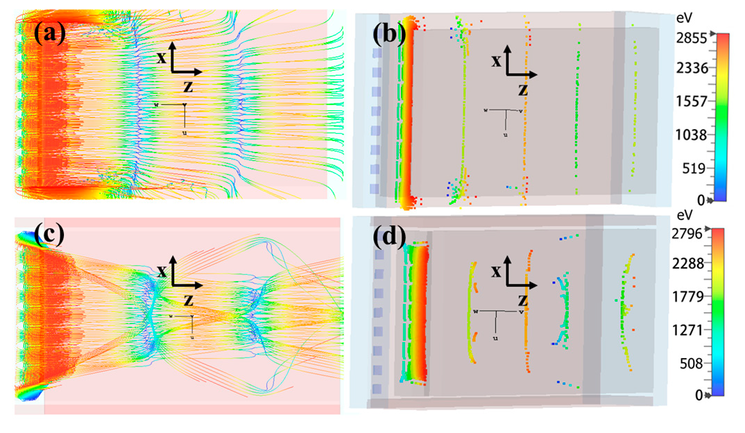
Two models, with and without axial end-hats, were used to analyze beam spreading. Figure 3 shows cases with and without end-hats. The top-down view shows the electron trajectories and their spread from space charge. The highly cycloidal beams demonstrate the necessity of including end-hats to confine the beam axially.
Without the electrostatic end-hats, which are biased at the sole potential, the electrons exit the device roughly half-way down the structure (Figure 3a,b). The end-hats provide electron confinement (Figure 3c,d). Hence, we use end-hats in the remaining simulations. Note that the color intensity in these trajectory plots indicates the electron kinetic energy (eV), with the peak energy at the top of the cycloid. These color intensity plots are also used through the remaining figures.

4. Simulation Results

4.1. Effect of Magnetic Field and Current Density

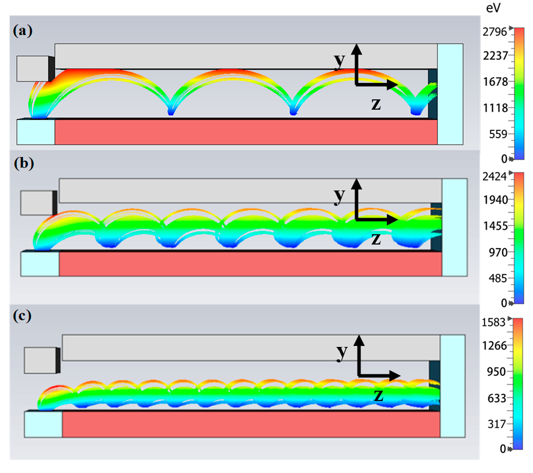
The instability study entails performing simulations for the parameters listed in Table 1. Specifically, we fixed the anode-sole distance at 20 mm, and characterize the variation in current density by varying the magnetic field strength from 0.01 T to 0.05 T with a step size of 0.01 T. Magnetic field variation was also used to examine the cycloidal beam and Hull cutoff. Figure 4 shows the simulated electron trajectories, demonstrating the cycloidal beam for magnetic field strengths of 0.01 T (B < BH), 0.015 T and 0.02 T (B > BH) for D = 20 mm. Increasing the magnetic field causes the beam to approach the Brillouin state as the cycloid radius decreases; however, the Brillouin instability is not present, and the cycloids are uniform.
However, the magnetic field must be sufficiently strong to insulate the anode. We endeavor to operate with a sufficiently low current density to achieve stability for B > BH. For a 3 kV anode voltage, 1.5 mA of injected current, Equation (1) gives BH = 0.009 T for D = 20 mm. Using D = 20 mm provides greater flexibility for experimental and simulation parametric studies. To ensure that we are operating within acceptable current density ranges for D = 20 mm, we used Equation (2) for 3 kV to show that 27 mA/cm2 < Jc < 94 mA/cm2 for our range of D and B. These values set the range of our simulation runs for 0.01 T B 0.05 T.
Comparing theoretical predictions of the instability of the crossed-field configuration to the simulation requires examining the electron trajectories in the simulations. Figure 5 shows three views of the simulation of electron trajectories for a 20 mm anode to sole gap.
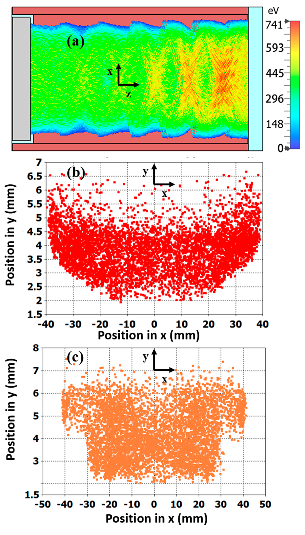
Figure 5a provides a top view of the trajectory showing the beam propagating toward the end collector and the cycloidal pattern along both the magnetic field (x-direction) and the direction of propagation (z-direction) where the color intensity (energy in eV) is distributed uniformly. This also indicates stable propagation. Figure 5b,c, the cross-sectional scatter plots at the circuit middle and at the end collector, respectively, show that the trajectories are symmetric in the magnetic field direction with the maximum current density near the bottom of the structure. The converted current densities from the collected current at both of the cross sections are ≈1.45 mA/cm2, which also confirms the uniformity. However, this location depends upon where the cut is taken along the cycloidal pattern.
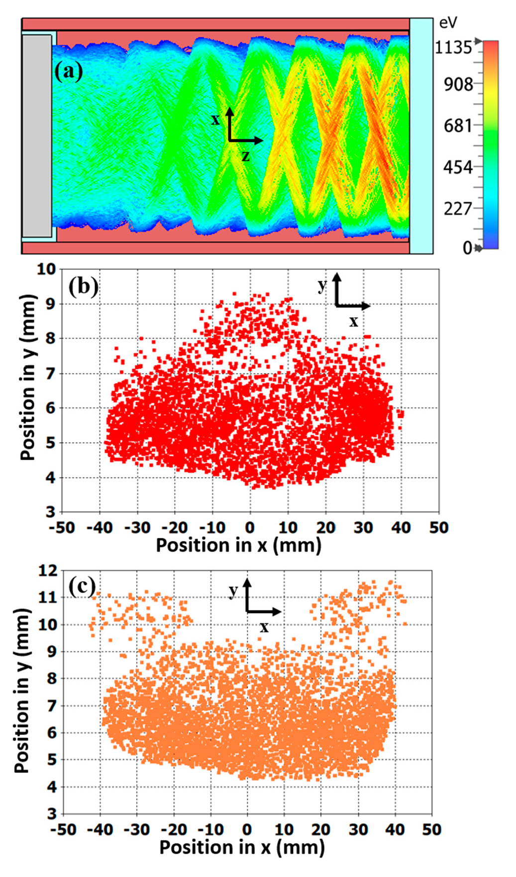
Figure 6 and Figure 7 show simulation results using injected current of I = 100 mA and 250 mA, respectively. Figure 6a shows that the cycloidal beam is still relatively uniform over the sole for 100 mA current, and the two cross-sectional views for the circuit center and the end collector, shown in Figure 6b,c, respectively, exhibit only slight changes, indicating transition to instability. However, for the 250 mA injected beam case, the intensity plot (Figure 7a) of the beam shows a significant change in the intensity of trajectories along the device length, which indicates a disturbance in stability when compared to Figure 5. Additionally, the calculated current densities from the 2-D cross section scatter plots at the center (Figure 7b) and the end collector (Figure 7c) differ when they should be similar, indicating instability.
Determining the critical current density in the model requires converting the beam current to the current density at the center and the end of device. Figure 8 shows the current density at these two locations as functions of input (Figure 8a) and beam (Figure 8b) current. The input current is the current injected at the cathode source; however, some of this current is lost in the scrape off on the anode and electrodes. The beam current was calculated from the simulation at the measurement location. In Figure 8b, the current density is the same at both locations until the total beam current is approximately 150 mA, when the current densities begin to diverge. The local current density at this deviation is just below 100 mA/cm2, which is close to Jc = 94 mA/cm2 from Equation (2), indicating a change in device stability. The sharp transition occurs at a beam current of 275 mA and a current density of 100–125 mA/cm2, which is also above Jc from Equation (2).
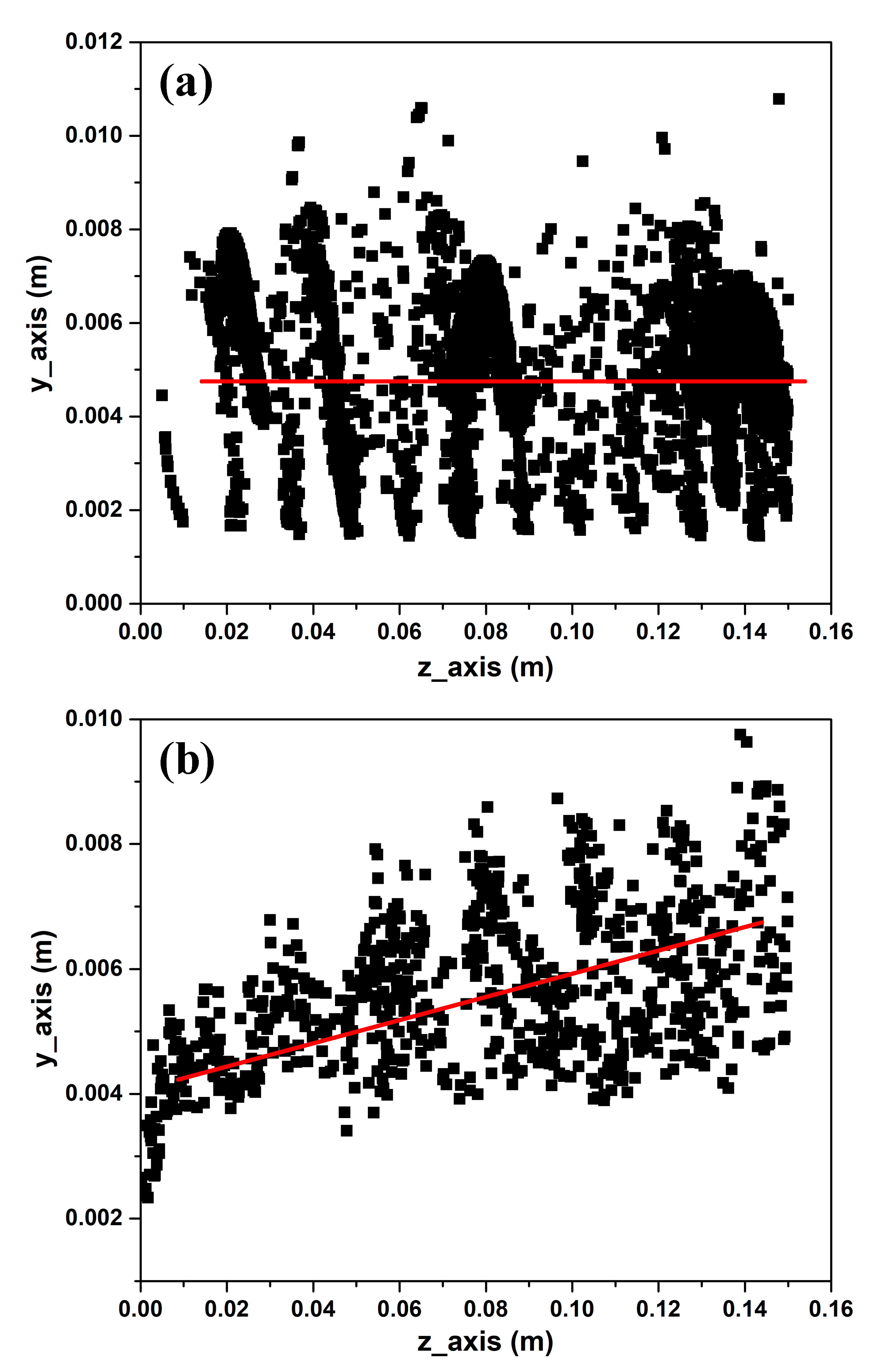
To quantify the instability from the 3-D particle trajectory, we analyzed a 2-D phase space cross-section (y-z), captured at the circuit middle (x = 0). The complete 2-D beam cycloidal trajectory in y and z is shown in Figure 9a,b for injected currents of 1.5 mA and 250 mA, respectively, with D = 20 mm and B = 0.05 T for both cases. Figure 9a shows the low current case, which is below the critical current density. Here, the electron orbits vary about a roughly straight line parallel to the z-axis, as indicated by the red line. For the higher input current case, shown in Figure 9b, the electron orbits are moving away from the sole as indicated by the red line. Although the orbits approach an unstable state where the magnetic field starts failing to isolate the beam and the beam starts to lose the uniform cycloidal pattern, this is not a near-Brillouin state [5,11,12]. First, this model is for an injected beam and not an emitting sole in which electrons are injected from the sole electrode. Classical theory states that the near-Brillouin state [31] occurs when sufficient space charge density builds up in the gap to make the electric field near the sole zero, causing cycloidal orbits of the newly entering electrons and, therefore, the whole flow, to become nearly laminar. In this injected beam model, electrons cycloid at a location above the sole and do not reduce the electric field at the sole surface. In addition, a new study [32] argues that there is practically no threshold current density for this state to occur. Accordingly, the phenomenon observed here is a transition to unstable beam propagation rather than to a near-Brillouin state.
The behavior for these cases was characterized by drawing best fit lines through the 2-D electron orbits, as indicated by the red lines. The slope of the line is 0.0047 with an intercept of 0.00531 for the 1.5 mA injected current case; whereas the slope is 0.01396 and the intercept is 0.00458 for the 250 mA injected current case. For a stable beam, the slope of the trajectory line (z-axis) goes through the center of the cycloids. As the cycloid becomes unstable, the slope increases, as shown in Figure 9b. The ratio of the slope to intercept provides the variation in cycloidal orbits in terms of the height of the cycloid (y-axis) over the propagation length (z-axis) with respect to the center of the orbit of each cycloid. The calculated variation for the 1.5 mA injected current is ≈11% and for the 250 mA injected current is >300%. This much higher variation for the 250 mA injected current clearly indicates instability in the beam propagation.

4.2. Effect of Magnetic Field Tilt

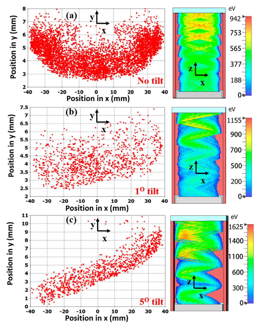
We next examined the effect of a tilt in the magnetic field to compare to the analytic 1-D theory [11], which showed that tilting B in the x-direction causes an instability at J = Jcr given by Equation (4), which is lower than the PCF critical current density Jc defined in Equation (2). From Equation (4), tilting the magnetic field by 1° and 3° induces instability at 0.24Jc and 0.3Jc, respectively. Simulations were carried out using a current density just below the maximum stable current density Jc (<100 mA/cm2) described in Figure 8, but the magnetic field was tilted with respect to the anode-sole gap.
Figure 10 shows beam trajectories for (a) 0°, (b) 1°, and (c) 5° magnetic field tilts with respect to anode-sole gap. Figure 10b shows that a 1° tilt of the magnetic field completely destabilizes the beam, and a 5° tilt (Figure 10c) almost rotates the beam after the instability described by Equation (4).
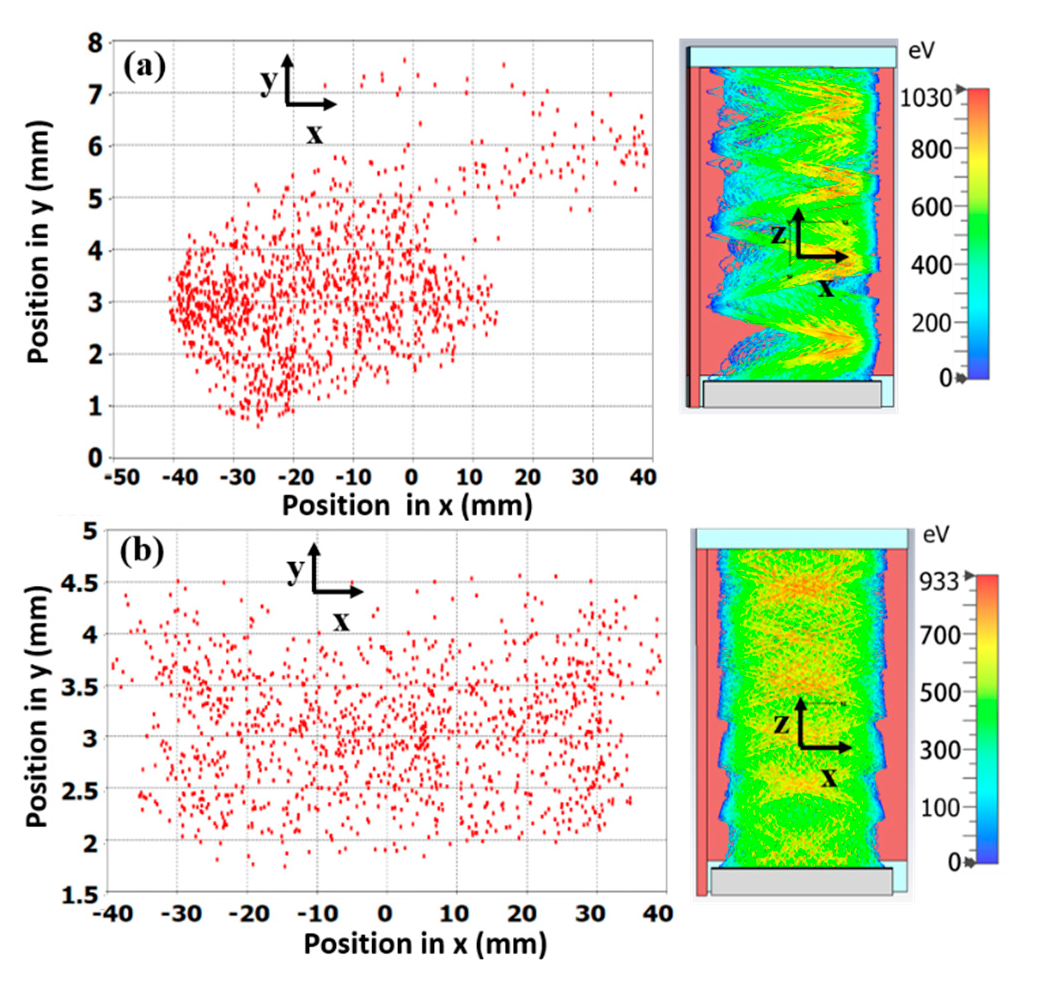
To demonstrate the transition of propagation from stable to unstable, the case of a 3° tilt was studied where Equation (4) gives Jcr = 0.3Jc. Two simulations were carried out using input currents of 20 mA and 50 mA for a 3° tilt. Figure 11a shows that a 50 mA input current gives J ≈ 39 mA/cm2 in the center of the gap which is greater than Jcr ≈ 28 mA/cm2 (adjusted critical current density). The electrons form nonuniform orbits as they traverse to the anode, which ultimately forms an unstable beam trajectory. However, a 20 mA input current yields J ≈ 18.72 mA/cm2, which is lower than the adjusted critical current density Jcr. Figure 11b shows that the orbits are nominally stable.
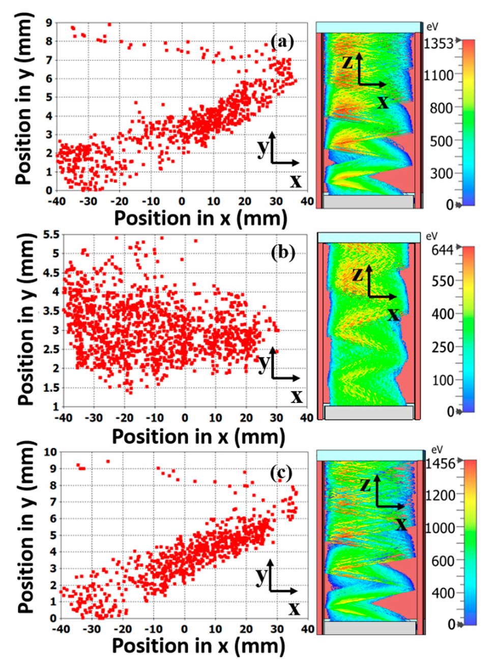
Additionally, 1-D PIC simulations [11] previously demonstrated the presence of bands of instability and stability for various magnetic field misalignments and current densities. For similar parameters (B = 0.05 T, D = 20 mm) and a 5° tilt, 1-D PIC simulations [11] showed stable flow for 0 < J < 0.133Jc and 0.33Jc < J < 0.4Jc, but unstable flow between those bands, where Jc ≈ 100 mA/cm2. This means that current densities between 33 mA/cm2 and 40 mA/cm2 would be stable for a 5° tilt. Figure 12 shows the simulation results for an injected beam of (a) 50 mA, (b) 70 mA, and (c) 90 mA, which, at the center of the gap, produces an effective current density of J ≈ 26 mA/cm2, J ≈ 36 mA/cm2, and J ≈ 43 mA/cm2, respectively, for a 5° tilt.
Among these three current densities, only J ≈ 36 mA/cm2, which falls between 0.33Jc (≈33 mA/cm2) and 0.4Jc (≈40 mA/cm2), produces stable beam propagation, which matches prior 1-D PIC simulation results [11].
To confirm this stability, we drew a best fit line through the complete orbitals from the phase space plots, yielding a slope and intercept of 0.00486 and 0.00637, respectively, for the 36 mA/cm2 case. From the slope and intercept, the calculated variation is ≈23% which denotes the beam is nominally stable given the relatively similar variation to the previously considered stable condition.
However, for J ≈ 26 mA/cm2 (0.26Jc < 0.33Jc), Figure 12a shows unstable propagation and a rotated beam. Similarly, for J ≈ 43 mA/cm2 (0.43Jc > 0.4Jc), Figure 12c shows unstable propagation and a rotated beam, which matches previous 1-D PIC simulations [11], confirming the presence of stability bands in 3-D. We did not calculate slopes and intercepts for the final two cases (injected beams of 50 mA and 90 mA) because the propagation instability is evident from the 3-D beam trajectories (Figure 12a,c).

5. Discussion

We have developed a 3-D simulation model of a basic crossed-field device for comparison with 1-D space charge limited theories for a PCF geometry [5], and examined the effect of magnetic field, current density, and magnetic field misalignment [11]. The results show that, for a fixed gap distance, the crossed-field beam has a stable band of propagation for a fixed magnetic field. The results from the 3-D simulations for the PCF agree reasonably well with the 1-D PCF theory for maximum stable current density. Tilting the magnetic field by 1° destabilizes the beam for a current density much lower than the critical value for the PCF [5] and in agreement with the simple 1-D model accounting for magnetic field misalignment [11]. We also observed the presence of instability and stability bands for various magnetic field misalignments and current densities, as predicted by the previous 1-D study [11].

6. Conclusions and Future Works

We conclude that the simple 1-D theories and PIC simulations for PCF and magnetic field misalignment agree well with the 3-D simulation results and may be used for more complex designs for magnetrons and CFAs, particularly as these theories are extended to cylindrical geometries. In particular, understanding the limitations of current density and magnetic field tilt in crossed-field devices will allow improved modeling and application of these devices. Future experiments will be carried out to further validate the 3D injected beam simulation and the stability predictions. Additionally, a more complex, cylindrical crossed-field geometry will be studied theoretically using approaches applied to non-magnetic field conditions [21,22], by simulation, and by experiment in future work.

Author Contributions

Conceptualization, R.B. and J.B.; Methodology and Simulations, R.B.; Theory and Calculations; A.M.D.; writing—original draft preparation, R.B.; writing—review and editing, J.B., A.L.G and A.M.D.; supervision, J.B.; project administration, J.B.; funding acquisition, J.B. and A.L.G. All authors have read and agreed to the published version of the manuscript.

Funding

Material support for this work is provided by the Air Force Office of Scientific Research under award number FA9550-19-1-0101.

Institutional Review Board Statement

Not applicable.

Informed Consent Statement

Not applicable.

Data Availability Statement

Not applicable.

Conflicts of Interest

The authors declare no conflict of interest.

References

  1. Andreev, D.; Kuskov, A.; Schamiloglu, E. Review of the Relativistic Magnetron. Matter Radiat. Extrem. 2019, 4, 067201. [Google Scholar] [CrossRef] [Green Version]
  2. Nicholls, N.S.; Damon, L.; Scoffield, B.P. Reduction of Noise in High-Power Crossed-Field Amplifiers. Electron. Lett. 1973, 9, 398–399. [Google Scholar] [CrossRef]
  3. Browning, J.; Fernandez-Gutierrez, S.; Lin, M.C.; Smithe, D.N.; Watrous, J. Phase Control and Fast Start-up of a Magnetron Using Modulation of an Addressable Faceted Cathode. Appl. Phys. Lett. 2014, 104, 233507. [Google Scholar] [CrossRef] [Green Version]
  4. Lau, Y.Y.; Christenson, P.J.; Chernin, D. Limiting Current in a Crossed-field Gap. Phys. Fluids B 1993, 5, 4486–4489. [Google Scholar] [CrossRef]
  5. Christenson, P.J.; Lau, Y.Y. Transition to Turbulence in a Crossed-field Gap. Phys. Plasmas 1994, 1, 3725–3727. [Google Scholar] [CrossRef]
  6. Lopez, M.; Lau, Y.Y.; Luginsland, J.W.; Jordan, D.W.; Gilgenbach, R.M. Limiting Current in a Relativistic Diode under the Condition of Magnetic Insulation. Phys. Plasmas 2003, 10, 4489–4493. [Google Scholar] [CrossRef]
  7. Christenson, P.J.; Lau, Y.Y. One-Dimensional Modulational Instability in a Crossed-Field Gap. Phys. Rev. Lett. 1996, 76, 3324. [Google Scholar] [CrossRef] [PubMed]
  8. Chernin, D.P. Computer Simulations of Low Noise States in a High-Power Crossed-Field Amplifier. IEEE Trans. Electron Devices 1996, 43, 2004–2010. [Google Scholar] [CrossRef]
  9. Gritsunov, A.; Nikitenko, O. Probable Sources of a Noise in Crossed-Field Devices II. Generating Tubes. In Proceedings of the 4th IEEE International Conference on Vacuum Electronics, Seoul, Korea, 28–30 May 2003; pp. 248–249. [Google Scholar]
  10. Riyopoulos, S.A. Feedback-Induced Noise in Crossed Field Devices. IEEE Trans. Plasma Sci. 1992, 20, 360–369. [Google Scholar] [CrossRef]
  11. Garner, A.L.; Lau, Y.Y.; Chernin, D. Collapse of Cycloidal Electron Flows Induced by Misalignments in a Magnetically Insulated Diode. Phys. Plasmas 1998, 5, 2447–2453. [Google Scholar] [CrossRef]
  12. Christenson, P.J.; Chernin, D.P.; Garner, A.L.; Lau, Y.Y. Resistive Destabilization of Cycloidal Electron Flow and Universality of (Near-) Brillouin Flow in a Crossed-field Gap. Phys. Plasmas 1996, 3, 4455–4462. [Google Scholar] [CrossRef] [Green Version]
  13. Kaup, D.J.; Thomas, G.E. Chaotic Instabilities and Density Profiles in a Crossed-Field Electron Vacuum Device. In Proceedings of the Intense Microwave Pulses VII, Aerosense 2000, Orlando, FL, USA, 24–28 April 2000; International Society for Optics and Photonics: Bellingham, WA, USA, 2000; Volume 4031, pp. 54–64. [Google Scholar]
  14. Kurkin, S.A.; Badarin, A.A.; Koronovskii, A.A.; Frolov, N.S.; Hramov, A.E. Modeling Instabilities in Relativistic Electronic Beams in the CST Particle Studio Environment. Math. Models Comput. Simul. 2018, 10, 59–68. [Google Scholar] [CrossRef]
  15. Wadhwa, R.; Misra, V. Some Considerations for Reduction of Noise and Instability Improvement in High-Power Crossed-Field Devices. IEEE Trans. Electron Devices 1969, 16, 977–985. [Google Scholar] [CrossRef]
  16. Birdsall, C.K. Electron Dynamics of Diode Regions; Elsevier: Amsterdam, The Netherlands, 1966; ISBN 0-323-16241-X. [Google Scholar]
  17. Hull, A.W. The Effect of a Uniform Magnetic Field on the Motion of Electrons Between Coaxial Cylinders. Phys. Rev. 1921, 18, 31. [Google Scholar] [CrossRef] [Green Version]
  18. Neculaes, V.B.; Jones, M.C.; Gilgenbach, R.M.; Lau, Y.Y.; Luginsland, J.W.; Hoff, B.W.; White, W.M.; Jordan, N.; Pengvanich, P.; Hidaka, Y. Magnetic Priming Effects on Noise, Startup, and Mode Competition in Magnetrons. IEEE Trans. Plasma Sci. 2005, 33, 94–102. [Google Scholar] [CrossRef]
  19. Sisodia, M.L.; Wadhwa, R.P. Noise Reduction in Crossed-Field Guns by Cathode Tilt. Proc. IEEE 1968, 56, 94–95. [Google Scholar] [CrossRef]
  20. Kino, G.S.; Taylor, N.J. The Design and Performance of a Magnetron-Injection Gun. IRE Trans. Electron Devices 1962, 9, 1–11. [Google Scholar] [CrossRef]
  21. Darr, A.M.; Garner, A.L. A Coordinate System Invariant Formulation for Space-Charge Limited Current in Vacuum. Appl. Phys. Lett. 2019, 115, 054101. [Google Scholar] [CrossRef]
  22. Harsha, N.S.; Garner, A.L. Applying Conformal Mapping to Derive Analytical Solutions of Space-Charge-Limited Current Density for Various Geometries. IEEE Trans. Electron Devices 2020, 1–7. [Google Scholar] [CrossRef]
  23. Jones, M.C.; Neculaes, V.B.; White, W.; Lau, Y.Y.; Gilgenbach, R.M. Simulation of Rapid Startup in Microwave Magnetrons with Azimuthally Varying Axial Magnetic Fields. Appl. Phys. Lett. 2004, 84, 1016–1018. [Google Scholar] [CrossRef] [Green Version]
  24. Neculaes, V.B.; Jones, M.C.; Gilgenbach, R.M.; Lau, Y.Y.; Luginsland, J.W.; Hoff, B.W.; White, W.M.; Jordan, N.M.; Pengvanich, P.; Hidaka, Y. Magnetic Perturbation Effects on Noise and Startup in DC-Operating Oven Magnetrons. IEEE Trans. Electron Devices 2005, 52, 864–871. [Google Scholar] [CrossRef]
  25. Child, C. Discharge from Hot CaO. Phys. Rev. (Ser. I) 1911, 32, 492. [Google Scholar] [CrossRef]
  26. Langmuir, I. The Effect of Space Charge and Residual Gases on Thermionic Currents in High Vacuum. Phys. Rev. 1913, 2, 450. [Google Scholar] [CrossRef]
  27. CP Studio. CST Studio Suite; CP Studio: Darmstadt, Germany, 2019. [Google Scholar]
  28. Humphries, S., Jr. Numerical Modeling of Space-Charge-Limited Charged-Particle Emission on a Conformal Triangular Mesh. J. Comput. Phys. 1996, 125, 488–497. [Google Scholar] [CrossRef] [Green Version]
  29. Guerrera, S.A.; Akinwande, A.I. Nanofabrication of Arrays of Silicon Field Emitters with Vertical Silicon Nanowire Current Limiters and Self-Aligned Gates. Nanotechnology 2016, 27, 295302. [Google Scholar] [CrossRef] [PubMed]
  30. Guerrera, S.A.; Akinwande, A.I. Silicon Field Emitter Arrays with Current Densities Exceeding 100 A/Cm 2 at Gate Voltages below 75 V. IEEE Electron Device Lett. 2015, 37, 96–99. [Google Scholar] [CrossRef] [Green Version]
  31. Black, J.R.; Boyd, J.A.; Dombrowski, G.; Needle, J.; Peterson, W.; Ruthberg, S.; Welch, H.W.; Brewer, G.R.; Hok, G.; Batten, H.W. Theoretical Study, Design, and Construction of CW Magnetrons for Frequency Modulation: Quarterly Progress Report No. 2; University of Michigan: Ann Arbor, MI, USA, 1950. [Google Scholar]
  32. Chernin, D.; Jassem, A.; Lau, Y.Y. Thermal Electron Flow in a Planar Crossed-Field Diode. IEEE Trans. Plasma Sci. 2020, 48, 3109–3114. [Google Scholar] [CrossRef]
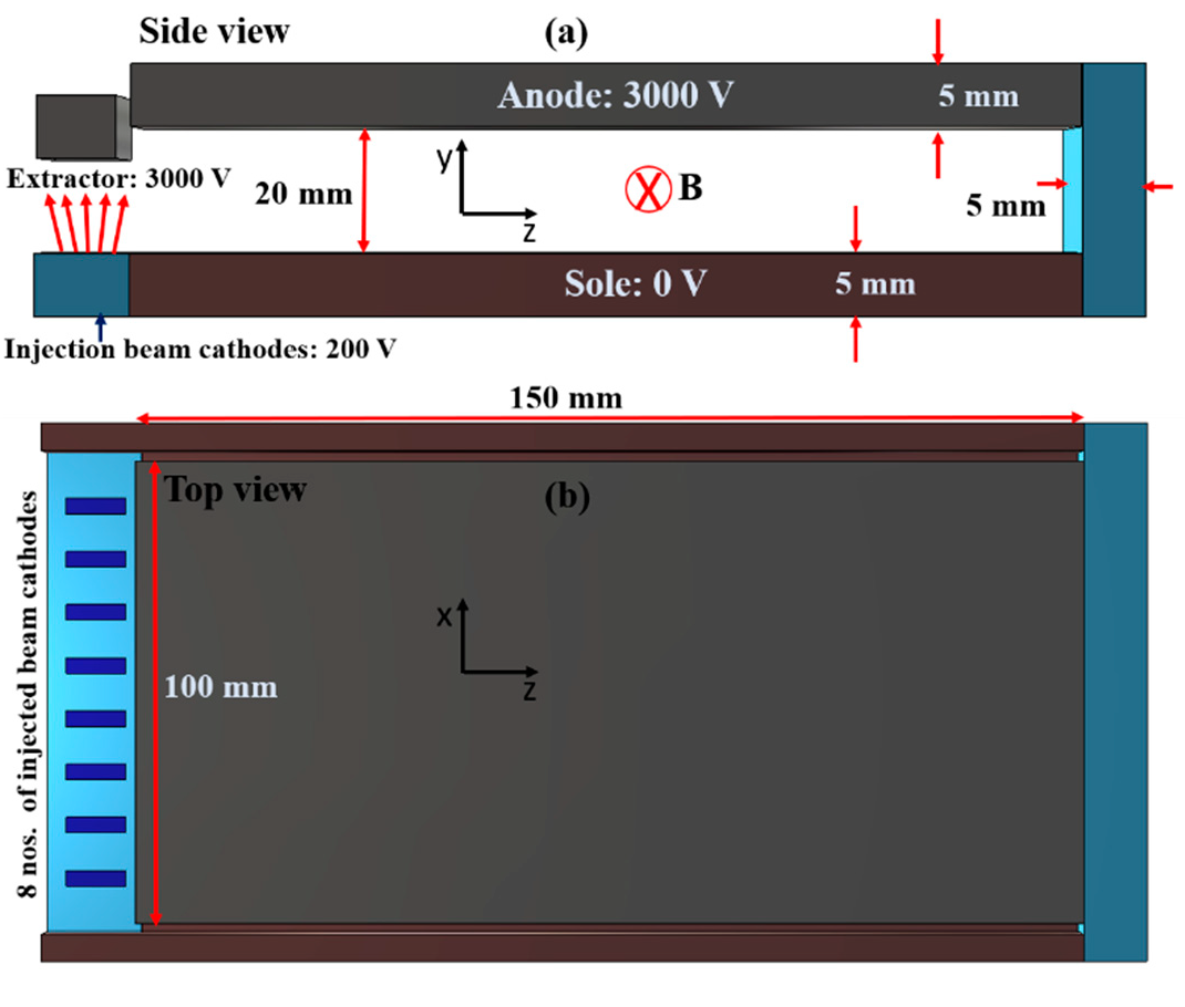
Figure 1. The 3-D model for simulation. (a) Side view. (b) Top view. The sole length is 150 mm and the width is 100 mm. The anode-sole gap was fixed at 20 mm. Eight discrete emitters are embedded inside of the dielectric emitter holder. For the simulation, a magnetic field perpendicular to the anode-sole gap was applied. A similar model will be used for the planned experiment.
Applsci 11 02540 g001
Figure 2. Planar crossed-field model used in CST with D = 20 mm and I = 1.5 mA. (a) Emitters (dark blue) embedded inside dielectric holder (light blue). (b) Electron beam hitting the extractor without the presence of magnetic field. The extractor is transparent here to show the emitters.
Applsci 11 02540 g002
Figure 3. Top down view of beam trajectories for CST model for (a) without and (c) with end-hats. Corresponding 2-D beam cross sections equally spaced in five locations over the sole is shown (b) without and (d) with end-hats. The applied magnetic field is 0.01 T with D = 20 mm and I = 1.5 mA. The color intensity of the trajectories indicates the kinetic energy of the electrons.
Applsci 11 02540 g003
Figure 4. Beam trajectories for D = 20 mm, I = 1.5 mA, and applied magnetic fields of (a) 0.01 T, (b) 0.015 T, and (c) 0.02 T showing the case just below (0.01 T) and above (0.015 T and 0.02 T) BH. The color intensity of the trajectories indicates the kinetic energy of the electrons.
Applsci 11 02540 g004
Figure 5. Beam trajectories for B = 0.05 T, D = 20 mm, I = 1.5 mA (a) Top view, (b) cross section at center of the circuit, and (c) cross section at the end collector, in the x-y plane. The color intensity of the trajectories indicates the kinetic energy of the electrons.
Applsci 11 02540 g005
Figure 6. Beam trajectories for B = 0.05 T, D = 20 mm, I = 100 mA: (a) top view, (b) cross section at circuit center and (c) cross section at end collector. The center and end cross section particle distributions look different; however, the current density is similar. The color intensity of the trajectories indicates the kinetic energy of the electrons.
Applsci 11 02540 g006
Figure 7. Beam trajectories for B = 0.05 T, D = 20 mm, I = 250 mA (a) Top view showing that the trajectories become unstable at the end of the structure. (b) Beam cross-section at the center of the device. (c) Beam cross section at the end collector. The color intensity of the trajectories indicates the kinetic energy of the electrons.
Applsci 11 02540 g007
Figure 8. Current density from CST simulation at two different locations (center, end collector) as a function of (a) injected current and (b) actual current for B = 0.05 T, D = 20 mm. There is a sharp transition in current density at a beam current of 275 mA and an input current of 500 mA.
Applsci 11 02540 g008
Figure 9. Phase space plot at y-z plane for (a) B = 0.05 T, D = 20 mm, I = 1.5 mA demonstrating a stable orbit and (b) B = 0.05 T, D = 20 mm, I = 250 mA demonstrating an unstable orbit indicating unstable beam propagation. The phase space data are obtained at the x = 0 plane.
Applsci 11 02540 g009
Figure 10. CST simulation showing a stable beam with B = 0.05 T, D = 20 mm, and I = 150 mA with (a) no tilt, (left center cross section. right: top view); (b) 1° tilt (left: center cross section. right: top view) and (c) 5° tilt (left center cross section. right: top view). The color intensity of the trajectories indicates the kinetic energy of the electrons.
Applsci 11 02540 g010
Figure 11. CST simulation for B = 0.05 T, D = 20 mm, and a 3° tilt for an input current of (a) 50 mA (left: center cross section, right: top view) and (b) 20 mA (left: center cross section, right: top view). The color intensity of the trajectories indicates the kinetic energy of the electrons.
Applsci 11 02540 g011
Figure 12. CST simulation for a 5° tilt with B = 0.05 T, D = 20 mm, and an input beam current of (a) 50 mA, (b) 70 mA and (c) 90 mA (left: center cross section, right: top view). The current density at circuit middle is (a) ≈26 mA/cm2, (b) ≈36 mA/cm2 and (c) ≈43 mA/cm2. The beam is nominally stable. The color intensity of the trajectories indicates the kinetic energy of the electrons.
Applsci 11 02540 g012
Table 1. Simulation parameters.
ParametersValueType of Study
Anode-Sole distance20 mmEffect on minimum stable current density
Magnetic field0.01 to 0.05 TMinimum magnetic field to insulate anode
Injected current1.5 mA to 1 AEffects along with the operable range of current density on beam stability
Magnetic field tilt 0° to 5°Effect of tilted magnetic field on beam stability
Table 2. Applied parameters.
PartApplied VoltageInjected Current
Sole0 V
Anode3000 V1.5 mA to 1 A
Emitter200 V
Publisher’s Note: MDPI stays neutral with regard to jurisdictional claims in published maps and institutional affiliations.