Article

Dirac Equation-Based Formulation for the Quantum Conductivity in 2D-Nanomaterials

Department of Information Engineering, Marche Polytechnic University, 60131 Ancona, Italy
*
Author to whom correspondence should be addressed.
Appl. Sci. 2021, 11(5), 2398; https://doi.org/10.3390/app11052398
Submission received: 5 February 2021 / Revised: 2 March 2021 / Accepted: 4 March 2021 / Published: 8 March 2021
(This article belongs to the Section Applied Physics General)

Abstract

:
Starting from the four component-Dirac equation for free, ballistic electrons with finite mass, driven by a constant d.c. field, we derive a basic model of scalar quantum conductivity, capable of yielding simple analytic forms, also in the presence of magnetic and polarization effects. The classical Drude conductivity is recovered as a limit case. A quantum-mechanical evaluation is provided for parabolic and linear dispersion, as in graphene, recovering currently used expressions as particular cases. Numerical values are compared with the ones from the literature in the case of graphene under d.c. applied field. In particular, the effect of the sample length and field strength on the conductivity are highlighted.

1. Introduction

Graphene has recently attracted intense attention in the research community due to its extraordinary mechanical, electronic and optical properties [1,2,3,4,5]. The advent of graphene as well as of other 2D-materials on one hand, the drive towards circuit miniaturization on the other hand, have led the analysis of carrier transport in low-dimensional systems as the key-development for the analysis and design of nanomaterials-based technological platform [6].
This area of research is at the intersection of electrodynamics and quantum transport, ranging from nanoscopic to mesoscopic dimensions [7].
Quantum currents and conductivity in nanostrcutures (graphene in particular) presents novel and intriguing aspects that have been the object of much interest in the last years [8,9,10,11,12,13,14,15,16,17,18,19,20,21,22,23,24,25,26,27,28,29,30,31].
For instance, in ref. [32] is found a useful synthesis of the peculiar features of currents at the nanoscale.
In evaluating this kind of situations with finite electron mass, use is currently made of Schrödinger equation from quantum mechanics in the framework of a free electron model, where the electron is described by a scalar wave-function. It is well appreciated, however, that such description is incomplete when polarization/magnetization aspects become important, e.g., in the very practical situation of applied electromagnetic fields, where using a four-component spinor description becomes necessary.
Moreover, in a conductor, the scalar ratio between the first pair of components of the spinor and the second pair plays the role of a characteristic impedance in a transmission line. The ratio of source impedance to load impedance is, in fact, an essential part of the correct definition of transmittivity.
In this work, we introduce a Dirac equation- based, free electron, ballistic model with finite mass under the action of a d.c. electric field in a highly idealized 2D-geometry. Electromagnetic boundary conditions of the field as well as the tensor character of the conductance are neglected. All real life loss mechanisms, such as intra-band transitions, interaction with the substrate, etc., are subsumed by a global finite life-time.
Considering just one–dimensional motion under the influence of a constant field, we then derive analytically the eigenvectors of the Dirac equation and find the resulting quantum current.
A Kubo-type approach is followed, including density of states and Fermi distribution, and obtain relatively simple analytical expressions valid for fields of moderate strength.
Numerical results are provided for the case of graphene conductivity, under d.c. condition.
We first consider the case of applying a constant bias, that is V ( x ) = V 0 , in order to compare the numerical results from the present method with respect the ones obtained by implementing the Kubo–Drude (KD) formulation [33,34]. The comparison shows excellent agreement, thus confirming the robustness of the present formulation.
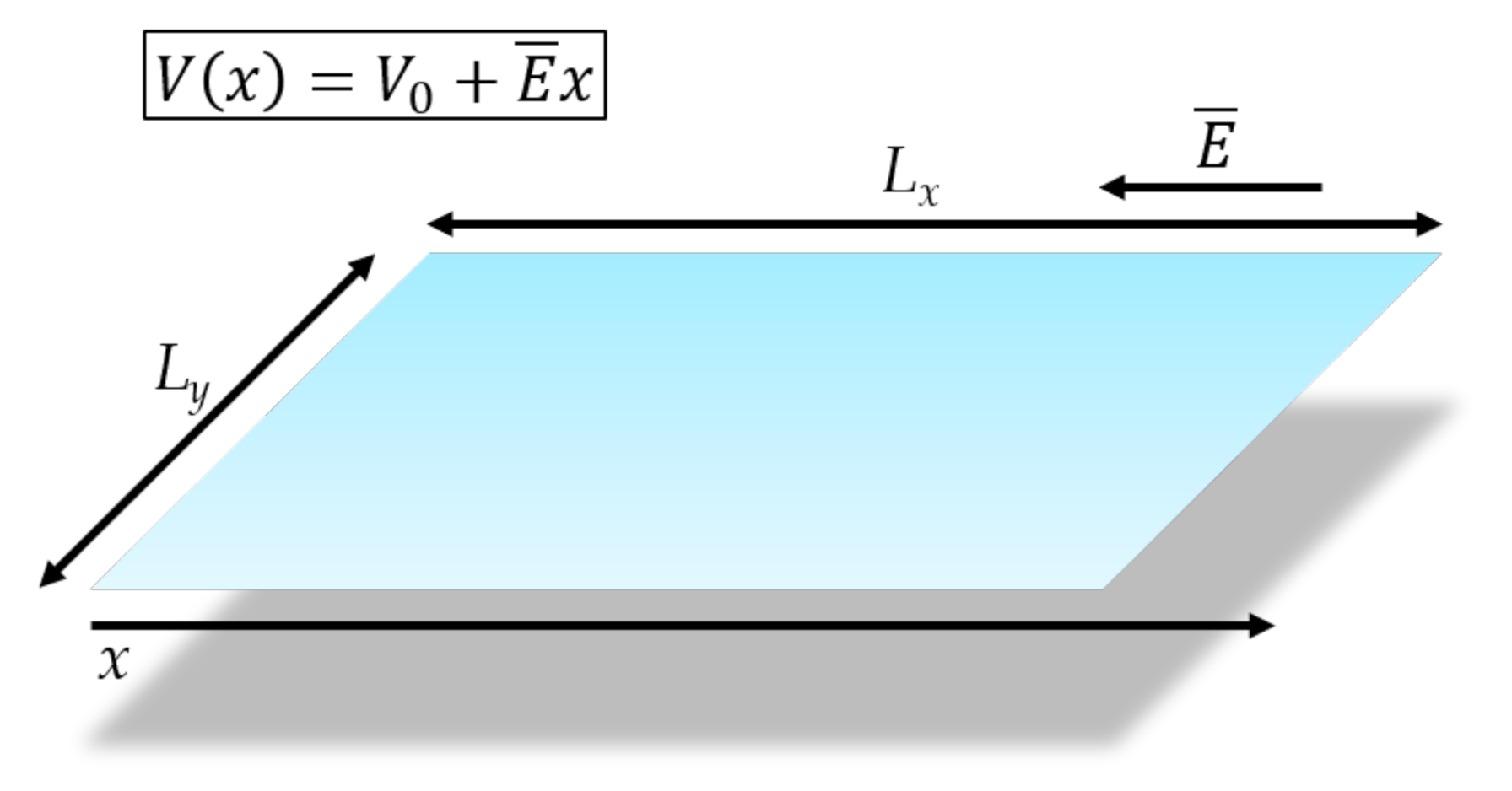
We then analyze the case of applying an electric field superposing the uniform bias, V ( x ) = V 0 + E ¯ x , as shown in Figure 1. The latter situation can be analyzed only by using the present Dirac-based formulation (DF); in fact, the KD formulation can only deal with the case of applying a constant bias along the structure. Moreover, the KD formula is based on a scalar wave function, and does not provide, e.g., any information about the particles spin. Indeed, the present formulation relies on a rigorous four-component spinor description, that can be used to provide, depending on the kind of problems (electric/magnetic polarization) a proper formulation for the spin wave propagation.

2. Dirac Equation-Based Model

We consider the 2-D problem of Figure 2, where a constant electric field E ¯ is applied in the negative x-direction over a strip of dimensions L x × L y . We assume motion in the x-direction and uniformity in y.
In writing Dirac equation applicable to the structure of Figure 2, Fermi velocity, v F , effective mass, m e , and lifetime in the band, τ , are given constants in the band of interest. The loss per unit length
1 v F τ = 1 L F ( L F > L x )
subsumes all mechanism, such as intraband transition, interaction with the substrate, etc. L f indicates the compound mean free path due to all loss mechanisms, L X is the actual sample length. The condition L F > L x means that the current, with some attenuation, reaches the output end of the sample. The condition L F > L x means that the current, with some attenuation, reaches the output end of the sample.
The only potential appearing in the Dirac equation is the d.c. potential V ( x ) = V 0 + E x x , where V 0 is the constant bias.
Our aim is to be able to compare with the results of current Schrödinger-based formulas at a given energy E in the interval k B T E μ , where k B is the Boltzmann constant, T the absolute temperature ( k B T = 25 meV) and μ is the chemical potential, that is, the upper energy level we consider still occupied. The latter can be considered as the superposition of the initial chemical potential, say the intrinsic Fermi level μ 0 = 2 E F , and the applied external potential E V , leading to μ = μ 0 + E V .
Now, in the Dirac equation we separate out the energy m e v F 2 = 2 E F ( E F indicates the energy at the Fermi surface) and set
i t = m e v 2 + E
in absence of losses ( L F ), Dirac equation is
i v F α x x ψ ¯ + β m e v F 2 ψ ¯ = [ m e v F 2 + E + | e | V ] ψ ¯
The 4 × 4 Dirac Matrices α , β appearing above are defined as
α x = 0 σ x σ x 0 ; β x = I 0 x 0 x I ; where σ x = 0 1 1 0
and are endowed with the following properties
α · α = 3 β 2 = 3 I 4 × 4 α β = β α
After pre-multiplying (1) by α x , we re-arrange in the form of an homogeneus system of four firs order differential equations over the semi-infinite interval 0 x with given boundary condition ψ ¯ ( 0 ) :
ψ ¯ = i K ( x ) ψ ¯
with K ( x ) 1 v F ( 2 E F + E + | e | V ) α x + 1 v F 2 E F β α x .
Considerable simplification in the following is obtained if | e | V is replaced by its average value over the interval x 0 ( x 0 is the length of an appropriate segmentation of the sample length L x ), E V = | e | ( V 0 + E ¯ x 0 2 ) so that K is now a constant matrix.
Using the specific properties of the Dirac matrices in the general solution of the linear system (2) (as given in ref. [35] for instance), the following useful result can be shown to hold.
ψ ¯ ( x ) = exp i K x ψ ¯ ( 0 ) = [ cos ( k x ) I + i sin ( k x ) k K ] ψ ¯ ( 0 )
Eigenvalues of K are given by:
k = ± 1 v F ( 2 E F + E + E V ) 2 ( 2 E F ) 2
and ± k represents the forward and backward propagation constants, respectively, with real k if E + E V 0 .
The eigenvectors (4-spinors) of K corresponding to ± k are of the form
ψ a = a η σ x a e i k x ψ b = b η σ x b e i k x
with
η = E + E V E + E V + 2 E F
Since E , E F are real and positive, if E + E V 0 , η is real; it becomes purely imaginary if E + E V 0 and E + E V + 4 E F > 0 , becoming real again when also E + E V + 4 E F < 0 , as summarized in Figure 3.
When E + E V < 0 , k is pure imaginary and (4) is modified as follows:
ψ a = a η σ x a e γ x ψ b = b η σ x b e γ x
with
γ = 1 v F ( 2 E F ) 2 ( 2 E F + E + E V ) 2
real, positive and η either real or pure imaginary.
Such modification is important in the definition of current.
The above spinors are orthogonal with weight α x ; a , b are constant 2D vectors determined by boundary conditions and normalization. In absence of y-dependence, these may be assumed as
a = a 2 1 1 b = b 2 1 1
The general solution (3) may be expressed as a linear combination of the above eigenvectors as a travelling wave or a standing wave with boundary condition ψ ¯ ( 0 ) . Let us now consider the case of constant, low loss that assumes negligible coupling due to loss between progressive and regressive waves. We may introduce this constant propagation loss in (2), by writing:
x ψ = 1 L F + i K ψ
The upper/lower sign refers to the progressive/regressive wave, respectively. We have
ψ = exp x L F ψ ¯ ( x )
The solution of (6) is their linear combination weighted by the exponentials:
ψ ( x ) = exp x L F ψ a + exp x L F ψ b
It is noted that the above two spinors modified by the exponentials are still orthogonal with weight α x , consistently with the original low loss assumption, that considers the original lossless wavefunction attenuated without altering their shape

3. Current: The Classical Drude Limit

At a fixed energy, the general definition of quantum current density from Dirac equation is
J ( x ) = | e | N v F ψ α x ψ
For E + E V 0 , we have
J ( x ) = J a J b = 2 | e | N v F E + E V E + E V + 4 E F | a | 2 exp 2 x L F | b | 2 exp 2 x L F
where N is the charge density per unit area. For E + E V < 0 and E + E V + 4 E F > 0 , we have instead
J ( x ) = 4 | e | N v F E + E V E + E V + 4 E F Im ( a b * )
Furthermore, finally for E + E V < 0 and E + E V + 4 E F < 0 ,
J ( x ) = 2 | e | N v F E + E V E + E V + 4 E F | a | 2 exp 2 x L F 2 γ x | b | 2 exp 2 x L F + 2 γ x
According to (7), the current entering the junction from the left is
J a ( 0 ) = 2 | e | N v F | a ( 0 ) | 2 E + | e | V 0 E + | e | V 0 + 4 E F
With a view to deriving an expression for conductivity under travelling wave condition, in (7) we only retain the progressive wave term.
Moreover, in order to recover the classic Drude formula, the normalization |a(0)| 2 is fixed so that
J a ( 0 ) = | e | N v F Am 1 .
We have then
J ( x ) = | e | N v F e 2 x L F 1 + ϵ E + | e | V 0 1 + ϵ 4 E F + E + | e | V 0 1 2 .
with ϵ | e | E ¯ L x 2 .
The “weak applied field” condition means ϵ E + | e | V 0 1 Even in absence of bias applied to the sample, the minimum value of E is k B T at room temperature, which corresponds for a moderate field of, say, 400 Vm 1 , to a length of 125 μ m . Consequently, it is usually justified to expand (10) in series of ϵ E + | e | V 0 . To first order we find (the following equation has been corrected)
J ( x ) = | e | N v F e 2 x L F 1 + 1 2 ϵ 4 ( E + | e | V 0 ) .
With a review to recovering the classical Drude conductivity as a limit case, we set x = v F τ c = L c , where τ c is the classical mean time between collisions ( τ c < τ ) . This yields a conductivity at the energy E : (the following equation has been corrected)
σ = d J d E ¯ = e 2 N v F e 2 L c L F L x 4 ( E + | e | V 0 ) Ω 1
If we now choose a value of E in the middle of the Fermi sphere, that is
E = 1 2 E F = 1 4 m e v F 2 | e | V 0
together with v F τ c = L c and consider L c L F , we recover the classical Drude result:
σ = e 2 N m e τ c .
After this verification, it is required to obtain full quantum-mechanical expression of the Kubo-type [32] that can be compared with theoretical and experimental results in the current literature.

4. Full Quantum-Mechanical Calculation

Returning now to a ballistic regime with flow in the x-direction, uniform in y, the distance x in (10) is to be replaced by L x . Moreover, for a band of energies, the classical electron density N is to be replaced by a density of states, weighted over allowed energies, by the occupation probability and integrated from the thermal energy level, k B T at room temperature, up to the chemical potential μ . This means:
J = 2 | e | v F 1 L x L y exp 2 x L F k B T μ D ( E ) f ( E ) 1 + ϵ E + | e | V 0 1 + ϵ 4 E F + E + | e | V 0 1 2 d E
The pre-factor 2 in the above expression is due to two electrons of opposite spins finding place in a state.
Since we are considering a ribbon configuration, we assume the density of states of a two-dimensional system with parabolic E k characteristic first. The particular case of graphene will be considered later. In (12)
N S = π k 2 ( 2 π ) 2 L x L y is the number of states in k space , E = ( k ) 2 2 m e
D ( E ) = d N S d k d k d E = k 2 π L x L y m e 2 k = L x L y m e 2 π 2 = c o n s t .
The probability of occupation, shifted for the presence of bias, is [32]:
f = 1 1 + exp E ( μ μ 0 ) k B T
where it is recalled E V = | e | ( V 0 + E ¯ L x 2 ) , and μ = μ 0 + E V . Again in the limit of weak fields, we find from (12):
J = | e | 2 E F π 2 v F exp 2 L x L F k B T μ f ( E ) 1 + 1 4 | e | E ¯ L x E + | e | V 0 d E ,
and the conductivity is:
σ = d J d E ¯ = e 2 E F τ 2 π 2 exp 2 L x L F k B T μ f ( E ) 1 E + | e | V 0 d E Ω 1 ,
where τ L x v F is the “transit” time through the sample. At low temperatures, μ E F , f ( E ) 1 ; considering L x L F , the exponential is close to unity and (13) reduces to:
σ = e 2 E F τ 2 π 2 k B T μ 1 E + | e | V 0 d E .
Approximating the integral by the average value of its argument ( E = E F ) × the interval, we get
σ = e 2 τ μ 2 π 2 E F E F + | e | V 0 .
If, moreover, | e | V 0 E F , that is usually the case, (15) reduces to Equation (18) of ref. [36]. Equation (13) above, however, provides a more realistic ballistic model under more general conditions of room temperature, non negligible bias and finite lifetime in the band for parabolic E k characteristics.

5. Graphene

Graphene provides an important particular case, since the dispersion relation is assumed linear of the type:
E ( k ) = k m e v F 2 m e = v F k 2 ,
that implies a density of states:
D ( E ) = d N S d k d k d E = k 2 π L x L y 2 v F = 2 E π ( v F ) 2 L x L y .
The current density (12) is replaced by:
J = 4 | e | 1 π 2 v F exp 2 L x L F k B T μ E f ( E ) 1 + ϵ E + | e | V 0 1 + ϵ 4 E F + E + | e | V 0 1 2 d E .
Consequently, in the weak field limit condition, the (differential) conductivity is given by:
σ = d J d E ¯ = e 2 τ π 2 exp 2 L x L F k B T μ f ( E ) E E + | e | V 0 d E Ω 1
Approximating the integral as above, the limit value of (17) at low temperature is still (15), but differences appear at room temperature and in presence of non-negligible bias.

6. Results

In this section, we deal with the graphene conductivity calculation. We (i) first consider the case of applying a constant bias, that is V ( x ) = V 0 , in order to compare the numerical results derived from the present method, from Equation (17), and the ones obtained by implementing the well known Kubo–Drude formulation [33,34]. Then, we (ii) analyze the case of applying an electric field superposing the uniform bias (along the domain), V ( x ) = V 0 + E ¯ x . It has to be remarked that the Kubo–Drude formulation can only deal with the case of a constant applied voltage (i), whereas the present method is quite more general and deals with a potential varying along the graphene domain.

6.1. Graphene Conductivity under a Uniform Bias Potential

We consider the application of a uniform bias voltage V ( x ) = V 0 , ( E ¯ = 0 ), with V 0 [ 3 , 3 ] V. This comparison is a core issue in order to have a robust estimate and calibration of the present method. The present Dirac-based formulation is developed for a progressive 4-components spinor wave, excited from the x-axis left-side (see Figure 2), travelling to the right-side, where it is considered matched for x increasing to plus infinity, with the electric field increasing in the same direction. Then, for the range V 0 [ 0 , 3 ] V, we use Equation (17). The range V 0 [ 3 , 0 ] V leads to a symmetrical problem, corresponding to a wave excited on the right side and travelling to the left-side, matched for x decreasing to minus infinity, with the electric field increasing in the same direction.

6.1.1. Conductivity in Function of the Chemical Potential μ

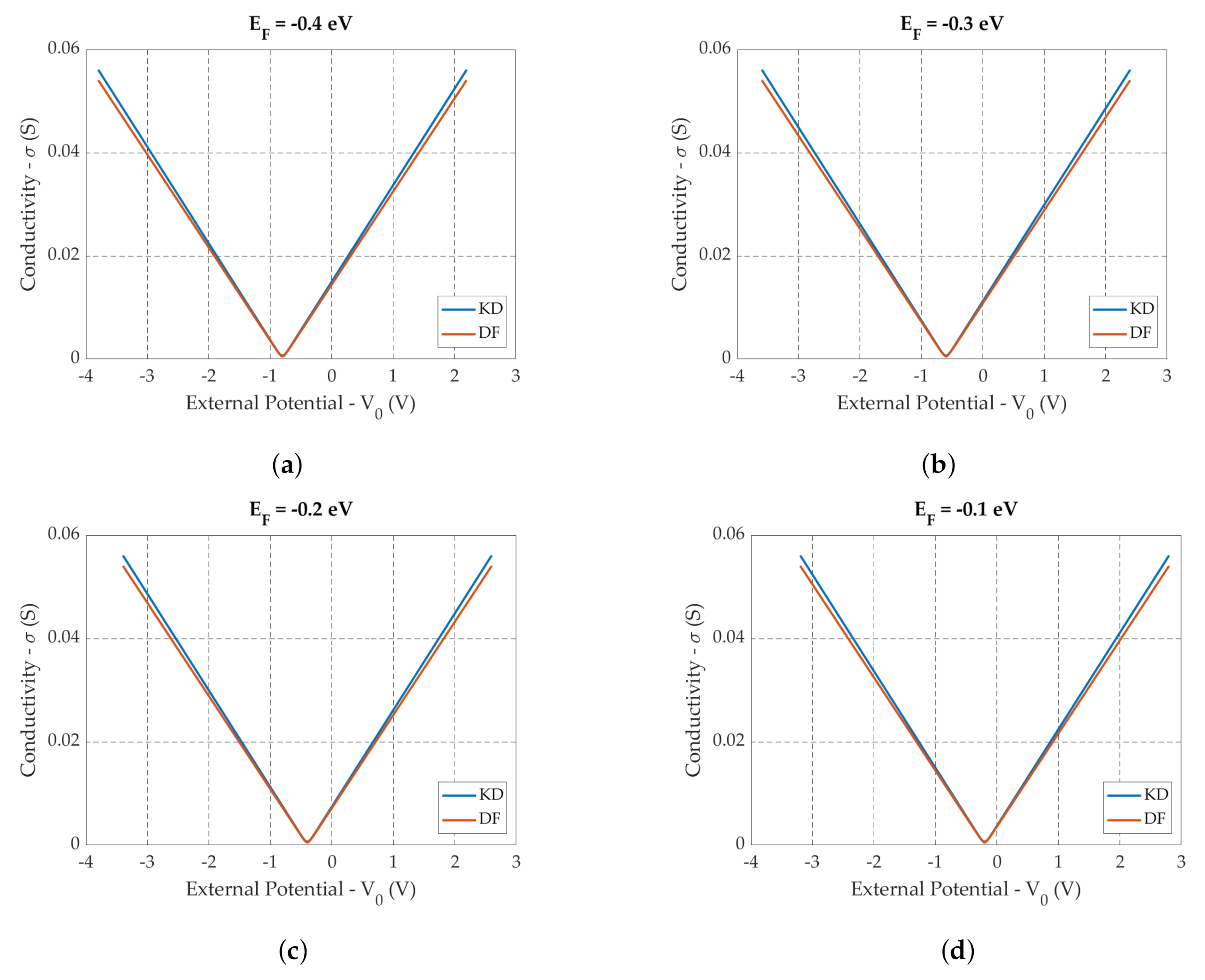
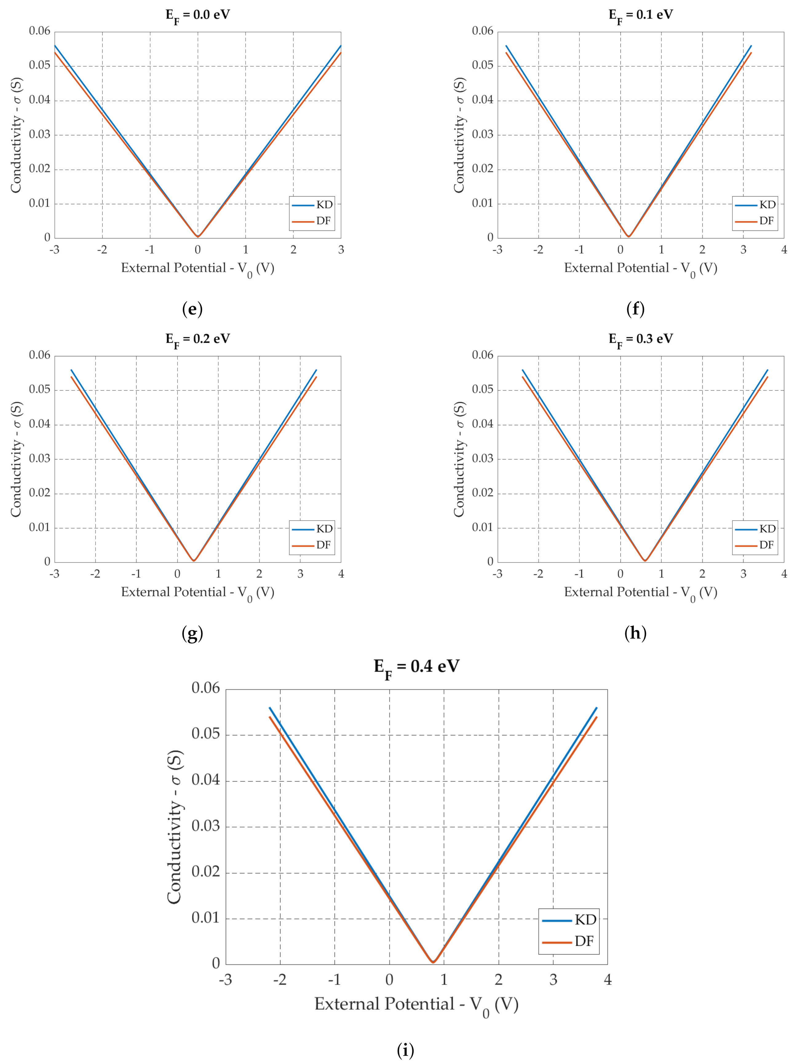
The comparison is performed, for both Equation (17) and the Kubo formula of ref. [33] in terms of (i) the same lifetime (scattering time) τ in the band, (ii) the same intrinsic chemical potential (pre-doping) μ 0 , and for V 0 [ 3 , 3 ] V; We recall that the intrinsic Fermi level is the initial Dirac point of the energy: it can be set to zero, but, realistically, under operative conditions there is a level shift caused by the doping (or gating), [34].
The plots shown in Figure 4 depict the conductivity in function of the applied external voltage for different values of the pre-doping Fermi level, μ . We can observe an excellent agreement among the curves, namely, the Kubo–Drude (blue) and Dirac formulation (red) curves. Moreover, the two sets of curves are symmetric with respect to μ 0 , thus confirming the ambipolar behaviour, one of the main properties of graphene as nano-structured material.

6.1.2. Conductivity in Function of the Scattering Time

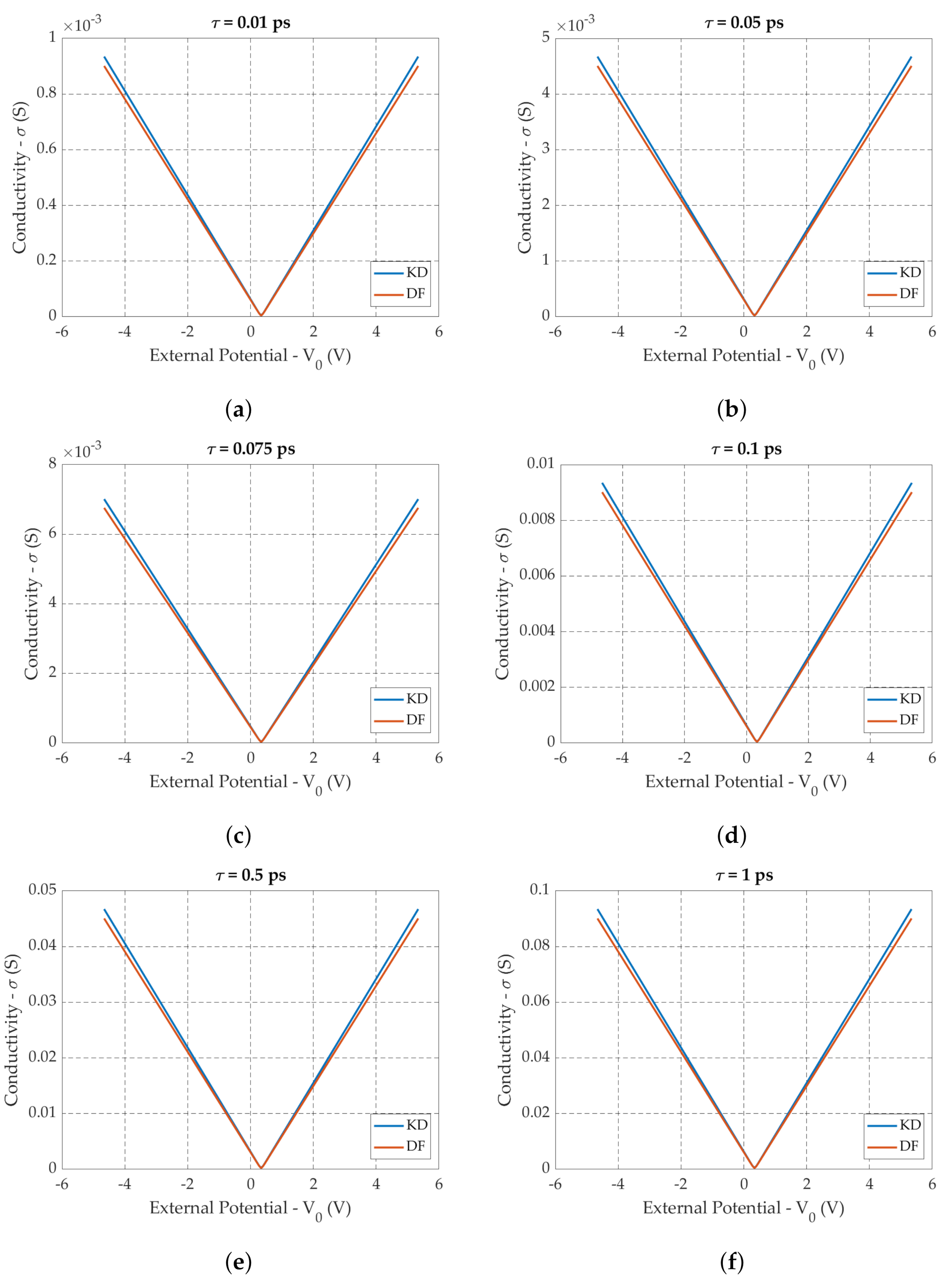
Again, the comparison shows and excellent agreement. In particular, we observe, from Figure 5, that if the scattering time increases, the conductivity linearly increases accordingly. All the calculations have been performed by setting μ 0 = 2 E F = 0.34 eV, a typical values in the experimental environments.

6.2. Graphene Conductivity by Applying a Longitudinal Electric Field E x

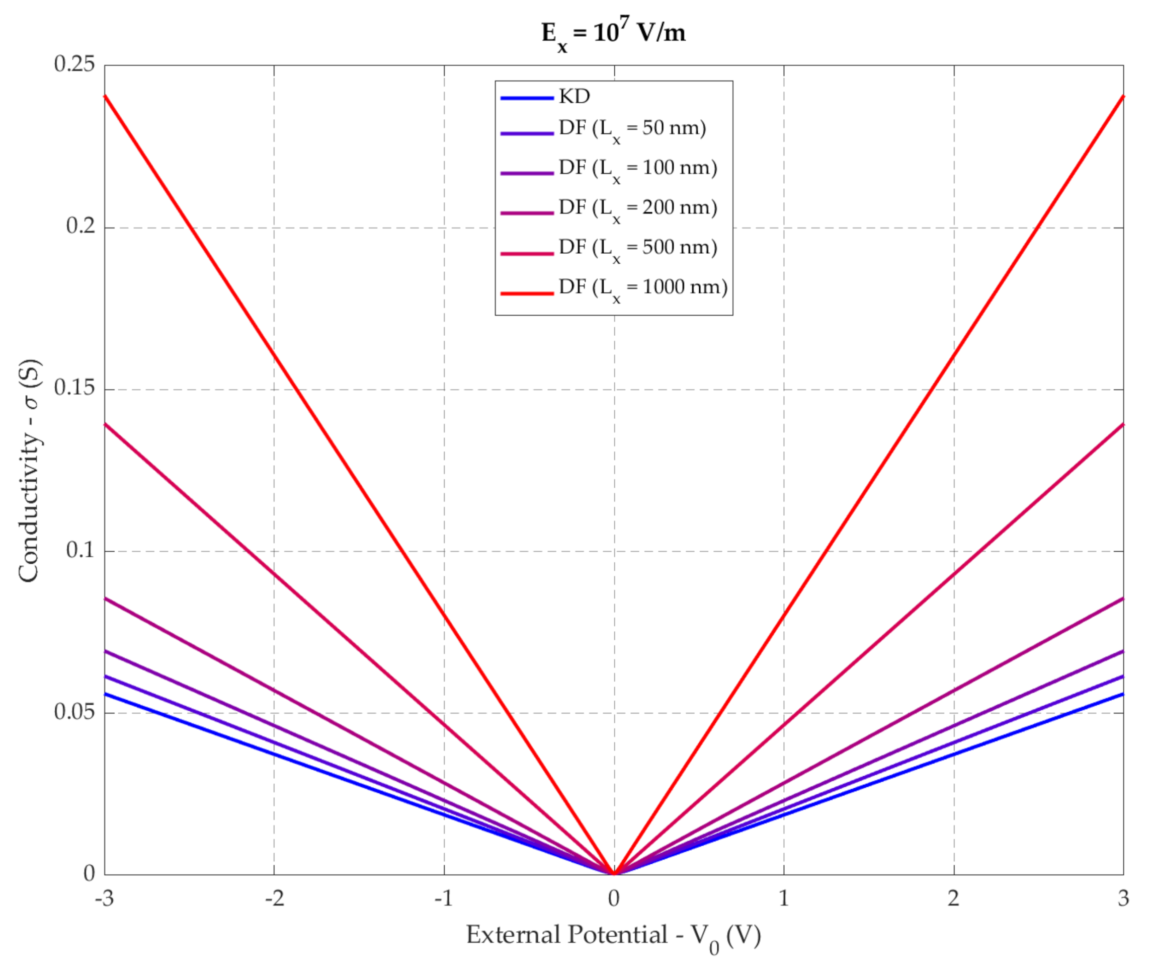
In this section, we analyze the behavior of the graphene conductivity in the realistic case of applying a longitudinal (x-direction in Figure 2) electric field, that superposes the bias potential, V ( x ) = V 0 + E ¯ x . This situation cannot be addressed by the Kubo–Drude formulation. In Equation (17), we set E ¯ = E x x ^ , with E ¯ = 10 7 (V/m) and, for sake of simplicity, consider μ 0 = 2 E F = 0 eV. We then calculate the conductivity for different values of L x lengths of the graphene domain, as shown in Figure 6. As a matter of fact, by increasing the length of the graphene sample, but still considering quantum transport in the ballistic regime (reasonably up to L x < 1 µm), we progressively increase the energy transferred to the material. This energy doping (shift of the Fermi level) corresponds to an increase of charge concentration, and, in turn, of conductivity. The behavior of the conductivity curves will then tend to flatten (saturation), further increasing the length of the sample and of the applied field (non-ballistic regime). The latter phenomen will be the object of future work. In Figure 6 is also reported the conductivity calculated from the Kubo–Drude formulation [33,34] that can only take into account the bias potential.

7. Conclusions

Starting from the Dirac equation mathematical model, based on a four-component spinor description, we derive a rigorous formulation of the scalar quantum conductivity for particles with finite mass, driven by a constant d.c. field. A quantum-mechanical evaluation is then provided in the case of parabolic and linear dispersion. The graphene conductivity is then analyzed. To this aim, numerical values derived from the present method are compared with the ones from the literature (Kubo formula), in the case of V ( x ) = V 0 , with excellent agreement. We then analyze the case of applying a uniform) electric field V ( x ) = V 0 + E ¯ x . The present formulation of the conductivity can be inserted into full-wave solver for the analysis and design of graphene-based devices in the ballistic regime [37], and in the quasi-ballistic regime, e.g., in geometrical diodes, [38].
The present method is as rigorous as it is flexible, and can be used to provide, depending on the particular problem (electric/magnetic polarization, d.c./a.c. conditions) proper formulation for charged particles wave propagation, e.g., spin waves, matter waves, electromagnetic waves.

Author Contributions

Conceptualization, T.R., L.P. and N.P.; software, L.P., N.P., M.O. and J.P.; validation, L.P. and N.P.; formal analysis, T.R., L.P., N.P., D.M., A.D.D.; data curation, N.P.; writing—original draft preparation, T.R., L.P. and N.P.; writing—review and editing, L.P. and N.P.; visualization, N.P.; supervision, L.P.; funding acquisition, L.P. All authors have read and agreed to the published version of the manuscript.

Funding

This project has received funding from the European Union’s Horizon 2020 research and innovation programme under grant agreement No 101006963 (GreEnergy).

Data Availability Statement

Data sharing not applicable.

Conflicts of Interest

The authors declare no conflict of interest.

References

  1. Novoselov, K.S.; Geim, A.K.; Morozov, S.V.; Jiang, D.; Zhang, Y.; Dubonos, S.V.; Grigorieva, I.V.; Firsov, A.A. Electric field effect in atomically thin carbon films. Science 2004, 306, 666–669. [Google Scholar] [CrossRef] [Green Version]
  2. Geim, A.K.; Novoselov, K.S. The rise of graphene. arXiv 2007, arXiv:cond-mat/0702595. [Google Scholar] [CrossRef]
  3. Morozov, S.V. Giant intrinsic carrier mobilities in graphene and its bilayer. Phys. Rev. Lett. 2008, 100, 602–616. [Google Scholar] [CrossRef] [Green Version]
  4. Blake, P.; Hill, E.W.; Castro Neto, A.H.; Novoselov, K.S.; Jiang, D.; Yang, R.; Booth, T.J.; Geim, A.K. Making graphene visible. Appl. Phys. Lett. 2007, 91, 063124. [Google Scholar] [CrossRef] [Green Version]
  5. Son, Y.W.; Cohen, M.L.; Louie, S.G. Energy gaps in graphene nanoribbons. Phys. Rev. Lett. 2006, 97, 216803-4. [Google Scholar] [CrossRef] [PubMed] [Green Version]
  6. Pierantoni, L.; Mencarelli, D.; Bozzi, M.; Moro, R.; Moscato, S.; Perregrini, L.; Micciulla, F.; Cataldo, A.; Bellucci, S. Broadband Microwave Attenuator Based on Few Layer Graphene Flakes. IEEE Trans. Microw. Theory Tech. 2015, 63, 2491–2497. [Google Scholar] [CrossRef]
  7. Rozzi, T.; Mencarelli, D.; Pierantoni, L. Towards a Unified Approach to Electromagnetic Fields and Quantum Currents From Dirac Spinors. IEEE Trans. Microw. Theory Tech. 2011, 59, 2587–2594. [Google Scholar] [CrossRef]
  8. Koppens, F.H.L.; Chang, D.E.; de Abajo, F.J.G. Graphene Plasmonics: A Platform for Strong Light–Matter Interactions. Nano Lett. 2011, 11, 3370. [Google Scholar] [CrossRef] [PubMed] [Green Version]
  9. Ju, L.; Geng, B.; Hornh, J.; Girit, C.; Martin, M.; Hao, Z.; Betchel, H.A.; Liang, X.; Zettl, A.; Shen, Y.R.; et al. Graphene plasmonics for tunable terahertz metamaterials. Nat. Nanotechnol. 2011, 6, 630. [Google Scholar] [CrossRef]
  10. Echtermeyer, T.; Britnell, L.; Jasnos, P.K.; Lombardo, A.; Gorbachev, R.V.; Grigorenko, A.N.; Geim, A.K.; Ferrari, A.C.; Novoselov, K.S. Strong plasmonic enhancement of photovoltage in graphene. Nat. Commun. 2011, 2, 458. [Google Scholar] [CrossRef] [Green Version]
  11. Christensen, J.; Manjavacas, A.; Thongrattanasiri, S.; Koppens, F.H.; García de Abajo, F.J. Graphene Plasmon Waveguiding and Hybridization in Individual and Paired Nanoribbons. ACS Nano 2011, 6, 431. [Google Scholar] [CrossRef] [PubMed] [Green Version]
  12. Smirnova, D.A.; Noskov, R.E.; Smirnov, L.A.; Kivshar, Y.S. Dissipative plasmon solitons in graphene nanodisk arrays. Phys. Rev. B 2015, 91, 075409. [Google Scholar] [CrossRef] [Green Version]
  13. Diaconescu, B.; Pohl, K.; Vattuone, L.; Savio, L.; Hofmann, P.; Silkin, V.M.; Pitarke, J.M.; Chulkov, E.V.; Echenique, P.M.; Farías, D.; et al. Low-energy acoustic plasmons at metal surfaces. Nature 2007, 448, 57. [Google Scholar] [CrossRef]
  14. Hartmann, R.R.; Kono, J.; Portnoi, M. Terahertz science and technology of carbon nanomaterials. Nanotechnology 2014, 25, 322001. [Google Scholar] [CrossRef] [PubMed]
  15. Low, T.; Avouris, P. Graphene Plasmonics for Terahertz to Mid-Infrared Applications. ACS Nano 2014, 8, 1086. [Google Scholar] [CrossRef] [PubMed] [Green Version]
  16. Grigorenko, A.N.; Polini, M.; Novoselov, K. Graphene plasmonics. Nat. Photonics 2012, 6, 749. [Google Scholar] [CrossRef]
  17. Novoselov, K.S.; Fal’ko, V.I.; Colombo, L.; Gellert, P.R.; Schwab, M.G.; Kim, K. A roadmap for graphene. Nature 2012, 490, 192. [Google Scholar] [CrossRef] [PubMed]
  18. García de Abajo, F.J. Graphene Plasmonics: Challenges and Opportunities. ACS Photonics 2014, 1, 135. [Google Scholar] [CrossRef] [Green Version]
  19. Pisarra, M.; Sindona, A.; Riccardi, P.; Silkin, V.; Pitarke, J. Acoustic plasmons in extrinsic free-standing graphene. New J. Phys. 2014, 16, 083003. [Google Scholar] [CrossRef] [Green Version]
  20. Farina, M.; Ye, T.; Lanzani, G.; Di Donato, A.; Venanzoni, G.; Mencarelli, D.; Pietrangelo, T.; Morini, A.; Keivanidis, P.E. Fast ultrahigh-density writing of low-conductivity patterns on semiconducting polymers. Nat. Commun. 2013, 4, 1. [Google Scholar] [CrossRef]
  21. Correas-Serrano, D.; Gomez-Diaz, J.S.; Alvarez-Melcon, A. On the Influence of Spatial Dispersion on the Performance of Graphene-Based Plasmonic Devices. IEEE Antennas Wirel. Propag. Lett. 2014, 13, 345. [Google Scholar] [CrossRef] [Green Version]
  22. Lovat, G.; Hanson, G.W.; Araneo, R.; Burghignoli, P. Semiclassical spatially dispersive intraband conductivity tensor and quantum capacitance of graphene. Phys. Rev. B 2013, 87, 115429. [Google Scholar] [CrossRef]
  23. Correas-Serrano, D.; Gomez-Diaz, J.S.; Perruisseau-Carrier, J.; Alvarez-Melcon, A. Spatially Dispersive Graphene Single and Parallel Plate Waveguides: Analysis and Circuit Model. IEEE Trans. Microw. Theory Tech. 2013, 61, 4333. [Google Scholar] [CrossRef]
  24. Louie, S.G.; Cohen, M.L. (Eds.) Chapter 6 electron transport. In Conceptual Foundations of Materials: A Standard Model for Ground- and Excited-State Properties; Contemporary Concepts of Condensed Matter Science; Elsevier: Amsterdam, The Netherlands, 2006; Volume 2, pp. 165–218. [Google Scholar]
  25. Gusynin, V.; Sharapov, S.; Carbotte, J. Magneto-optical conductivity in graphene. J. Phys. Condens. Matter 2007, 19, 026222. [Google Scholar] [CrossRef] [Green Version]
  26. Gusynin, V.; Sharapov, S.; Carbotte, J. Sum rules for the optical and Hall conductivity in graphene. Phys. Rev. B 2007, 75, 165407. [Google Scholar] [CrossRef] [Green Version]
  27. Hanson, G.W. Dyadic Green’s functions and guided surface waves for a surface conductivity model of graphene. J. Appl. Phys. 2008, 103, 064302. [Google Scholar] [CrossRef] [Green Version]
  28. Liang, L.H.; Wei, Y.G.; Li, B. Size-dependent interface phonon transmission and thermal conductivity of nanolaminates. J. Appl. Phys. 2008, 103, 084314. [Google Scholar] [CrossRef] [Green Version]
  29. Mencarelli, D.; Pierantoni, L.; di Donato, A.; Farina, M. Microwave characterization of anisotropic graphene by applying the Duality theorem. J. Comput. Electron. 2015, 14, 214. [Google Scholar] [CrossRef]
  30. He, X.Y.; Li, R. Comparison of Graphene-Based Transverse Magnetic and Electric Surface Plasmon Modes. IEEE J. Sel. Top. Quantum Electron. 2014, 20, 62. [Google Scholar]
  31. Gradshteyn, I.; Ryzhik, I. Table of Integrals, Series, and Products, 7th ed.; Academic Press: New York, NY, USA, 2007. [Google Scholar]
  32. Durkan, C. Current at the Nanoscale; College Press: Joplin, MO, USA, 2007. [Google Scholar]
  33. Hanson, G.W. Dyadic Green’s Functions for an Anisotropic, Non-Local Model of Biased Graphene. IEEE Trans. Antennas Propag. 2008, 56, 747. [Google Scholar] [CrossRef]
  34. Mencarelli, D.; Bellucci, S.; Sindona, A.; Pierantoni, L. Spatial dispersion effects upon local excitation of extrinsic plasmons in graphene micro-discs. J. Phys. D Appl. Phys. 2015, 48, 1–9. [Google Scholar] [CrossRef] [Green Version]
  35. Lancaster, P. Theory of Matrices; Academic Press: Cambridge, MA, USA, 1969. [Google Scholar]
  36. Hanson, G.W. Quasi-transverse electromagnetic modes supported by a graphene parallel-plate waveguide. J. Appl. Phys. 2008, 104, 084314. [Google Scholar] [CrossRef]
  37. Mencarelli, D.; Rozzi, T.; Pierantoni, L. Coherent Carrier Transport and Scattering by Lattice Defects in Single- and Multi-Branch Carbon Nanoribbons. Phys. Rev. B Condens. Matter Mater. 2008, 77, 195435-1–195435-11. [Google Scholar] [CrossRef]
  38. Passi, V.; Gahoi, A.; Lemme, M.C. Enhanced asymmetry in monolayer graphene geometric diodes. In Proceedings of the 2017 Silicon Nanoelectronics Workshop (SNW), Kyoto, Japan, 4–5 June 2017. [Google Scholar]
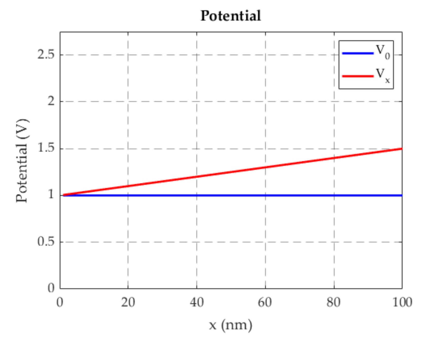
Figure 1. Potential in the structure (Sample length L x = 100 nm).
Applsci 11 02398 g001
Figure 2. 2-D schematic representation of the problem.
Applsci 11 02398 g002
Figure 3. Intervals which determine whether η is real or imaginary
Applsci 11 02398 g003
Figure 4. Conductivity of graphene calculated: (i) by the Dirac formulation (DF) of present method (red lines), and (ii) by the Kubo–Drude formulation (blue lines), for different values of the intrinsic Fermi level μ 0 = 2 E F (eV), and for V 0 [ 3 , 3 ] V.
Applsci 11 02398 g004aApplsci 11 02398 g004b
Figure 5. Conductivity of graphene calculated: (i) by the present method (red lines), and (ii) by the Kubo–Drude formulation (blue lines), for different values of the scattering time τ (s), being μ 0 = 2 E F = 0.34 eV, and for V 0 [ 3 , 3 ] V.
Applsci 11 02398 g005
Figure 6. Grapheneconductivity for different values of L x , in the the presence of the longitudinal electric field E ¯ = E x x ^ , being V 0 [ 3 , 3 ] V.
Applsci 11 02398 g006
Publisher’s Note: MDPI stays neutral with regard to jurisdictional claims in published maps and institutional affiliations.