Article

A Research Study on Protocol Stack of Space-Based Optical Backbone Network

1
State Key Laboratory of Information Photonics and Optical Communications, Beijing University of Posts and Telecommunications, Beijing 100876, China
2
Beijing Institute of Tracking and Telecommunication Technology, Beijing 100094, China
3
China Electronics Technology Group Corp 34th Research Institute, Guilin 541004, China
*
Author to whom correspondence should be addressed.
Appl. Sci. 2021, 11(5), 2367; https://doi.org/10.3390/app11052367
Submission received: 31 January 2021 / Revised: 2 March 2021 / Accepted: 4 March 2021 / Published: 7 March 2021
(This article belongs to the Section Electrical, Electronics and Communications Engineering)

Abstract

:
Facing the growing high data rate and large communication capacity demands, optical communications are widely recognized to be used to implement satellite communications. For a space-based optical backbone network, an appropriately designed protocol stack is important. In this paper, we proposed a protocol stack that is suitable for a space-based optical backbone network. Following this, we then used software to simulate this stack, built a hardware platform to test it, and finally, analyzed the results. The results showed that the proposed protocol stack was well designed to provide efficient control and management of the space-based optical backbone network. It could improve management efficiency by collecting resources and automatically calculating and building route paths. It could also facilitate data forwarding in intermediate satellite nodes with limited source and power, by using an advanced orbiting systems (AOS) frame switching scheme to avoid unnecessary processes, such as unpacking, upper-layer processing and repacking for passing services. The protocol stack could also support the use of unidirectional links to improve the link resource utilization. Finally, it could also provide transparent transmission for different kinds of services.

1. Introduction

With the development of the internet era, microwave communication can hardly meet the fast-growing high data rate and large communication capacity demands for satellite communications. Optical communications, with the advantage of large communication capacities, low power, small antenna size, and strong anti-interference capabilities, represent a potential technology for space communications [1]. Actually, optical space communications have a long history, which started with the temporal coincidence of the invention of the laser and the development of the first commercial satellites in the early 1960s [2]. However, optical space communication systems did not reach the commercial use stage until the emergence of some key technological breakthroughs over the following few decades.
The advent of high-speed space optical crosslinks made optical space communication possible and improved the performance of satellite network by leaps and bounds [3]. It was widely accepted that optical communications should be used to implement space communications in order to meet the growing high data rate and large communication capacity demands [4]. Furthermore, a global space-based optical backbone network became feasible, benefitting from the use of multi-gigabit laser inter-satellite links (ISLs) [5]. As a network which could provide large communication capacity and global seamless connections, the global space-based optical backbone network aroused researcher’s interests. In 2004, S. Chan proposed the design of a space-based information network backbone to provide high-speed space-to-space communication for space-based assets and shared on-orbit processing resources [6]. In 2017, W. Chen proposed an approach which consisted of constructing a virtual random satellite network from a satellite physical topology based on LEO(low earth orbit) [7]. In 2017, T. T. Li proposed a novel time slot based optical burst switching (OBS) architecture for GEO/LEO based satellite backbone networks where GEO means Geosynchronous Orbit [8]. We found that most of the published studies focused on hardware or algorithm design. As an important part of the space-based optical backbone network, networking protocols have not yet received sufficient attention. Regarding the spatial networking protocols, the Consultative Committee for Space Data Systems (CCSDS) developed a series of specifications and recommendations, such as the CCSDS protocol stack [9], which lays the protocol foundations of spatial data transmission. However, for a spaced-based optical backbone network that is capable of facing the internet era, these functions are not sufficient.
As the core bearer of future space-based network, the optical backbone network must meet the following demands: (1) Global seamless connections with high data rates and large communication capacities should be provided. (2) The transmission of various services should be supported. Furthermore, as a space network mainly consisting of satellites, the space-based optical backbone network is subject to several constraints, such as the limited resources and restricted performance due to the characteristics of satellites. In order to meet the demands mentioned above, we must resolve the following challenges: (1) How to support efficient management and control for a resource-limited optical network? (2) How to take full advantage of the restricted performance of satellites in a space-based optical backbone network? (3) How to provide transparent transmission for different kinds of services?
In order to solve these problems, we have undertaken various studies [10]. Based on such studies, we further propose a detailed design of a protocol stack that is suitable for the space-based optical backbone network. Then, we used software to simulate and built a hardware platform to test this protocol stack, before finally analyzing the results.

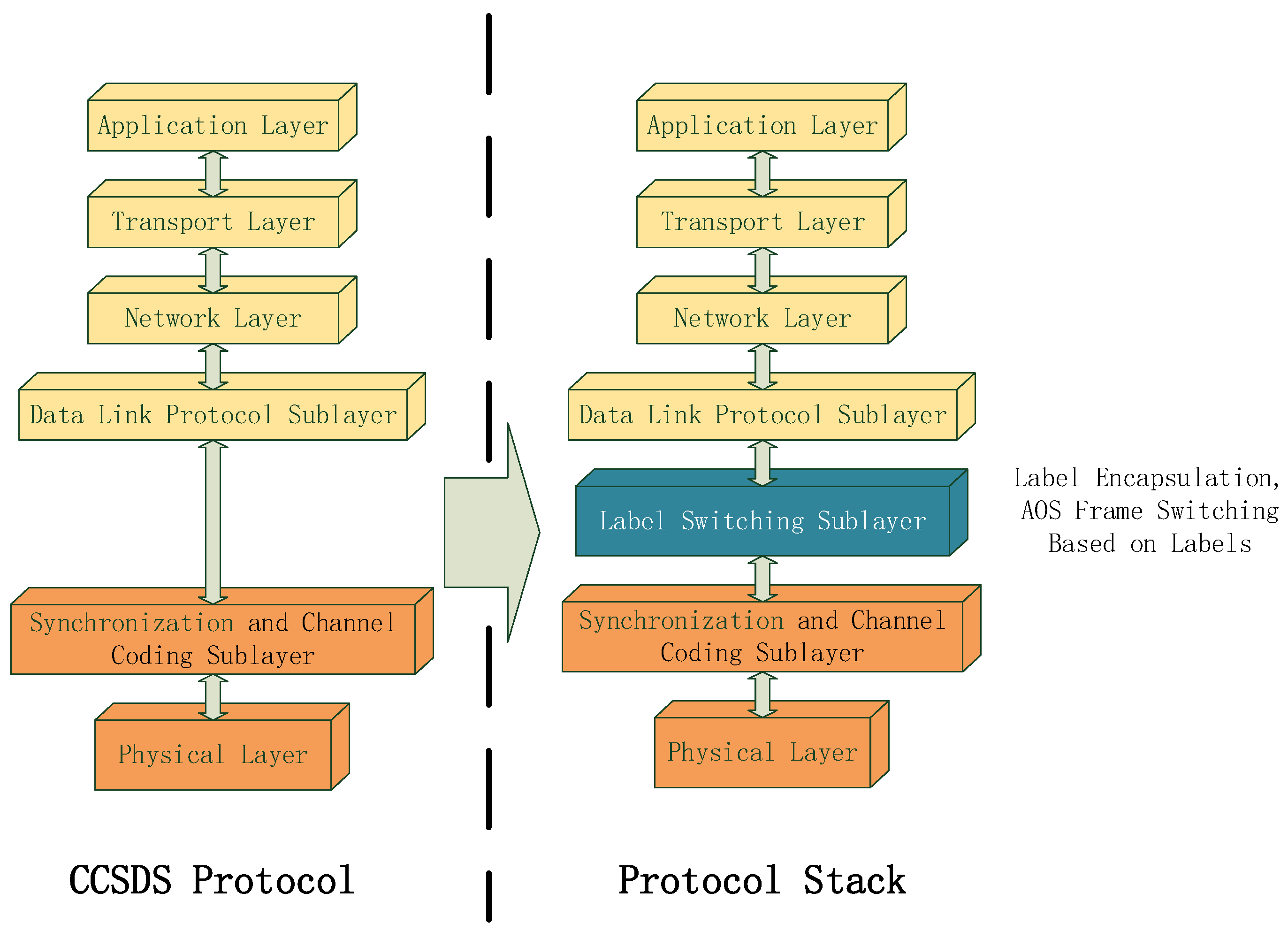
2. Architecture of the Protocol Stack

The CCSDS protocol stack mentioned above includes the Advanced Orbiting Systems (AOS) space data link protocol, a Layer 2 protocol that provides a framing layer between channel coding and higher-layer link multiplexing protocols. In order to support the design of protocol stack, we expanded the protocols of the CCSDS [11].
Figure 1 shows the model of the protocol stack, where we inserted a label switching sublayer between the synchronization and channel coding sublayer and the data link protocol sublayer. Accordingly, we expanded the structure of the AOS framework.
As shown in Figure 2, we inserted label, DCN (data communication network) and OAM (operation, administration and maintenance) fields in the AOS framework, the functions of which are defined as follows:
  • Label Field: carries a label to support the AOS frame switching scheme.
  • DCN Field: delivers control and management information, such as routing protocol or network management configuration messages.
  • OAM Field: transfers information to conduct functions of network monitoring and detection.
Different from the terrestrial network, the space-based optical backbone network, which is mainly composed of satellites and ISLs, is dynamic and unmaintainable because of the satellite characteristics. In addition, constrained by the quantity and volume, a satellite usually has weak performance, which could result in limited resources. That is to say, the protocol stack should support the efficient management and control of resources in order to improve resource utilization. Inspired by the architecture of the automatically switched optical network (ASON) [12], we designed the protocol stack in three function planes: management plane, control plane and transport plane.
As shown in Figure 3, the functions of the three planes were designed as follows:
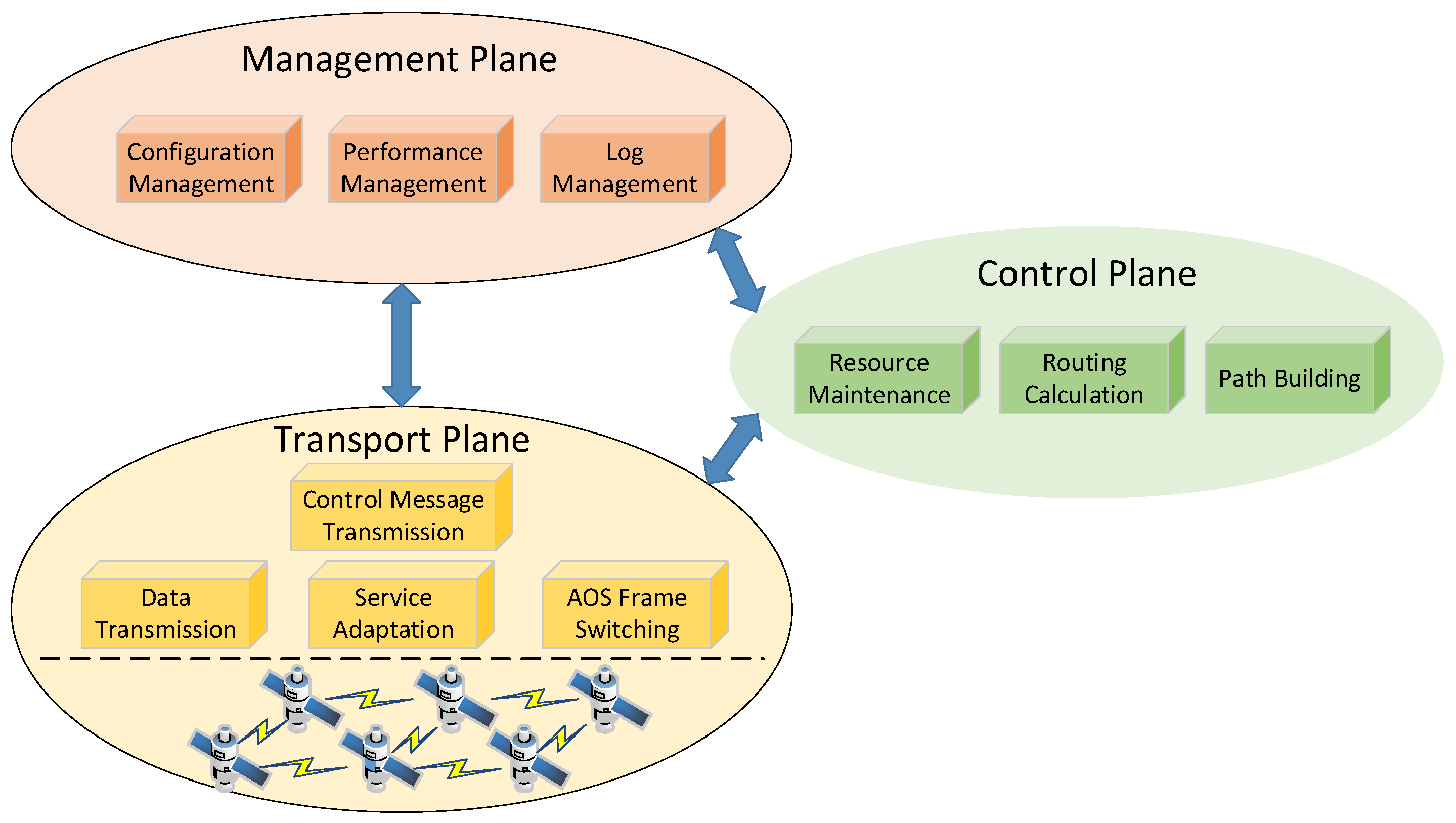
  • Management Plane: manages the whole network, with functions of configuration management, performance management, and log management, which helps the network manager manage the network efficiently.
  • Control Plane: controls the network automatically, with functions of resource maintenance, routing calculation and path building, which helps the network managers improve their work efficiency.
  • Transport Plane: transports data in the network, with functions of control message transmission, data transmission, service adaptation and AOS frame switching.
The management plane and control plane are highly synergistic and can both operate on the transport plane directly to implement the management and control of the network. The transport plane provides underlying support to guarantee the transmission of control information and service data.
As shown in Figure 4, it can be seen that each node (satellite or ground station) consists of three parts: a network management agent, control plane modules, and transport plane modules. The internal logical relationship in each plane is designed as follows:
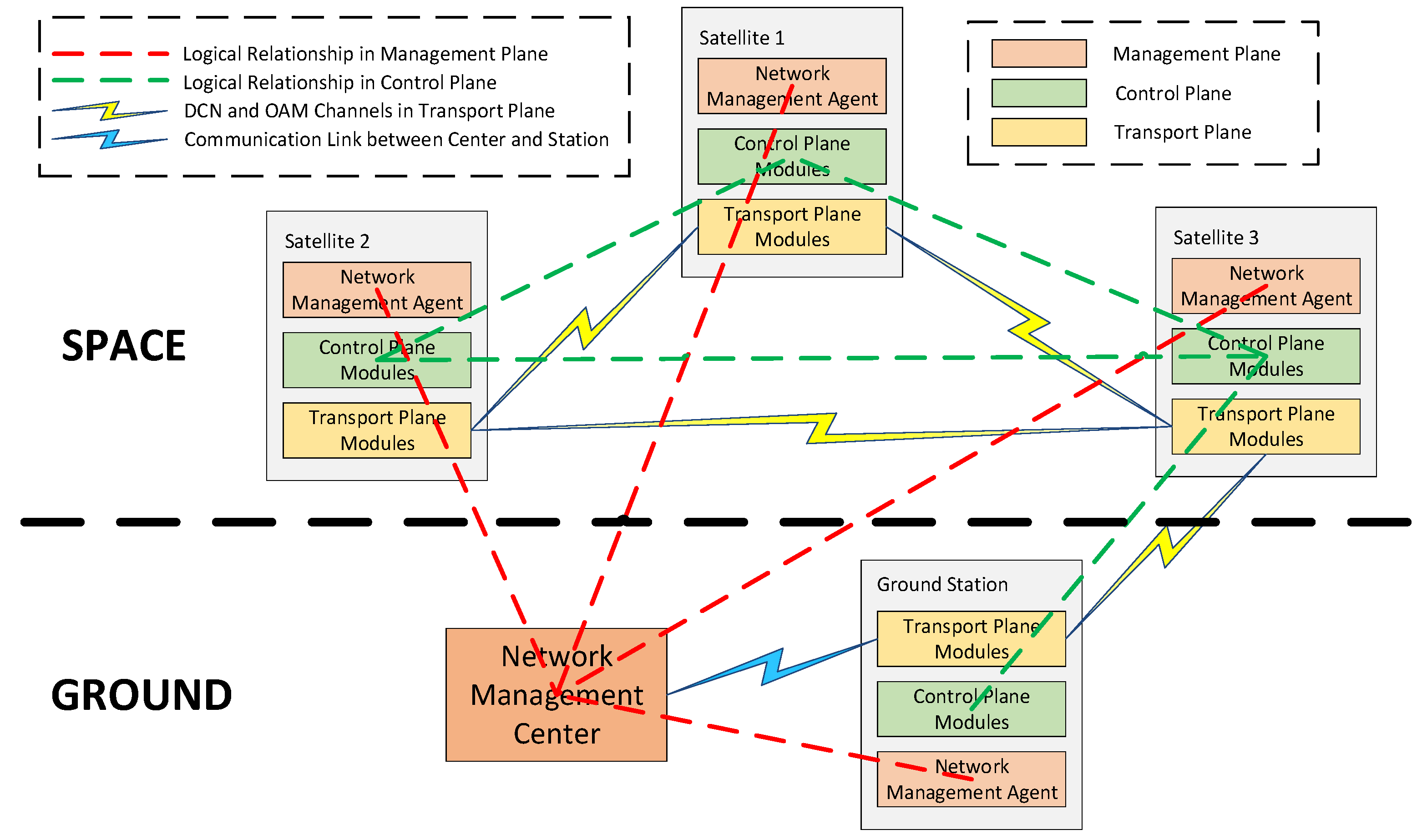
  • Management Plane: consists of a network management center (on the ground) and network management agent (in each node). The architecture (red dotted line) is a star schema, which means that the center logically manages each agent directly. The center connects to one of the ground stations (blue lighting) and then manages the whole network.
  • Control Plane: composed of control plane modules in all nodes. The architecture (green dotted line) is distributed, which means that the modules in all nodes have the same functions and the relationships between them are logically equal in the control plane. The control plane modules in different nodes collaborate with each other to implement the functions of the control plane.
  • Transport Plane: composed of transport plane modules in all nodes and the architecture is also distributed. However, the difference is that the modules in different nodes do not collaborate with each other. It provides DCN and OAM channels (yellow lightning) to transmit management and control messages.

3. Design of the Protocol Stack

In this paper, the design of the protocol stack focuses on the control plane and transport plane.

3.1. Design of Control Plane

Based on the discussion above, the control plane has functions including resource maintenance, routing calculation and path building. In order to implement these functions, the control plane consists of three protocols: the routing protocol, signal protocol and link management protocol.

3.1.1. Link Management Protocol

The link management protocol is the base of the protocol stack. It has two main functions: control channel management and local resource collection.
The function of control channel management establishes and maintains control channels, which transmit management and control messages. After the start of a node, each port sends Config messages periodically to negotiate for building control channels, until the ConfigAck message or ConfigNack message is received.
  • Receive the ConfigAck message: this means that the corresponding node has agreed on the content of negotiations sent by the Config message, including negotiated parameters such as Channel, HelloInterval, HelloDeadInterval and so on. In this case, the control channel has already been built.
  • Receive the ConfigNack message: this means that the corresponding node has disagreed on the content of the negotiations sent by the Config message and replied the ConfigNack message, including the recommended negotiated parameters, which should be prioritized by this node. If this node disagrees on these recommended negotiated parameters, it could resend new negotiated parameters.
After the control channels have been established, the link management protocol also needs to maintain them by periodically sending Hello messages in each control channel. If a port has not received any Hello message from a control channel within the fixed time (HelloDeadInterval), the port will determine that the control channel is invalid. The functions of the messages and parameters mentioned above are defined as follows:
  • Config message: used to negotiate for the establishment of control channels, including parameters about the control channels.
  • ConfigAck message: used to reply to the Config message while the node has agreed on the negotiated parameters.
  • ConfigNack message: the message—including the recommended parameters—is used to reply to the Config message when the node disagrees with the negotiated parameters.
  • Hello message: this message is sent periodically to maintain the control channels built by the link management protocol.
  • Channel: used to confirm the parameters of a control channel, such as specific wavelength, specific field and so on. Here, we used specific field to realize control channels.
  • HelloInterval: used as the interval at which the Hello messages are sent.
  • HelloDeadInterval: used as the maximum time to decide whether a control channel is invalid. If the port has not received any Hello message within the time, the control channel is invalid.
Based on the control channels established above, several messages, such as the LinkSummary message, LinkSummaryAck message and LinkSummaryNack message, could be transmitted to implement the function of local resource collection. This could collect and maintain local resources, which could be used by a routing protocol to calculate route paths. The port would send LinkSummary messages periodically, including link-related parameters such as bandwidth, port rate and so on, until it has received the LinkSummaryAck message or LinkSummaryNack message.
  • Receive the LinkSummaryAck message: means that the corresponding node has agreed on the link-related parameters sent by the LinkSummary message. In this case, the link parameters have been confirmed and will be collected by the link management protocol.
  • Receive the LinkSummaryNack message: means that the corresponding node has disagreed on the link-related parameters sent by the LinkSummary message and replied to the LinkSummaryNack message, including stating that the parameters could not be accepted. This node could resend new parameters again until they both come to an agreement.
The functions of messages mentioned above are defined as follows:
  • LinkSummary message: used to confirm the link-related parameters.
  • LinkSummaryAck message: used to reply to the LinkSummary message when the node agrees on the link-related parameters.
  • LinkSummaryNack message: used to reply to the LinkSummary message when the node disagrees on the link-related parameters, including the parameters that could not be accepted.
Based on the design discussed above, the link management protocol can build and maintain control channels to support the transmission of management and control messages. It can also collect local resources to support resource collection and route path calculation in the routing protocol.

3.1.2. Routing Protocol

The routing protocol is used to support functions such as automatic neighbor discovery, resource maintenance and route calculation. Here, we used the improved OSPF (open shortest path first) protocol as the routing protocol, which could collect and maintain resources of the whole network and support the use of unidirectional links.
Figure 5 shows the state machine of signal protocol which has been improved to support the use of unidirectional links. It can be seen that there are nine states in the state machine, which are defined as follows:
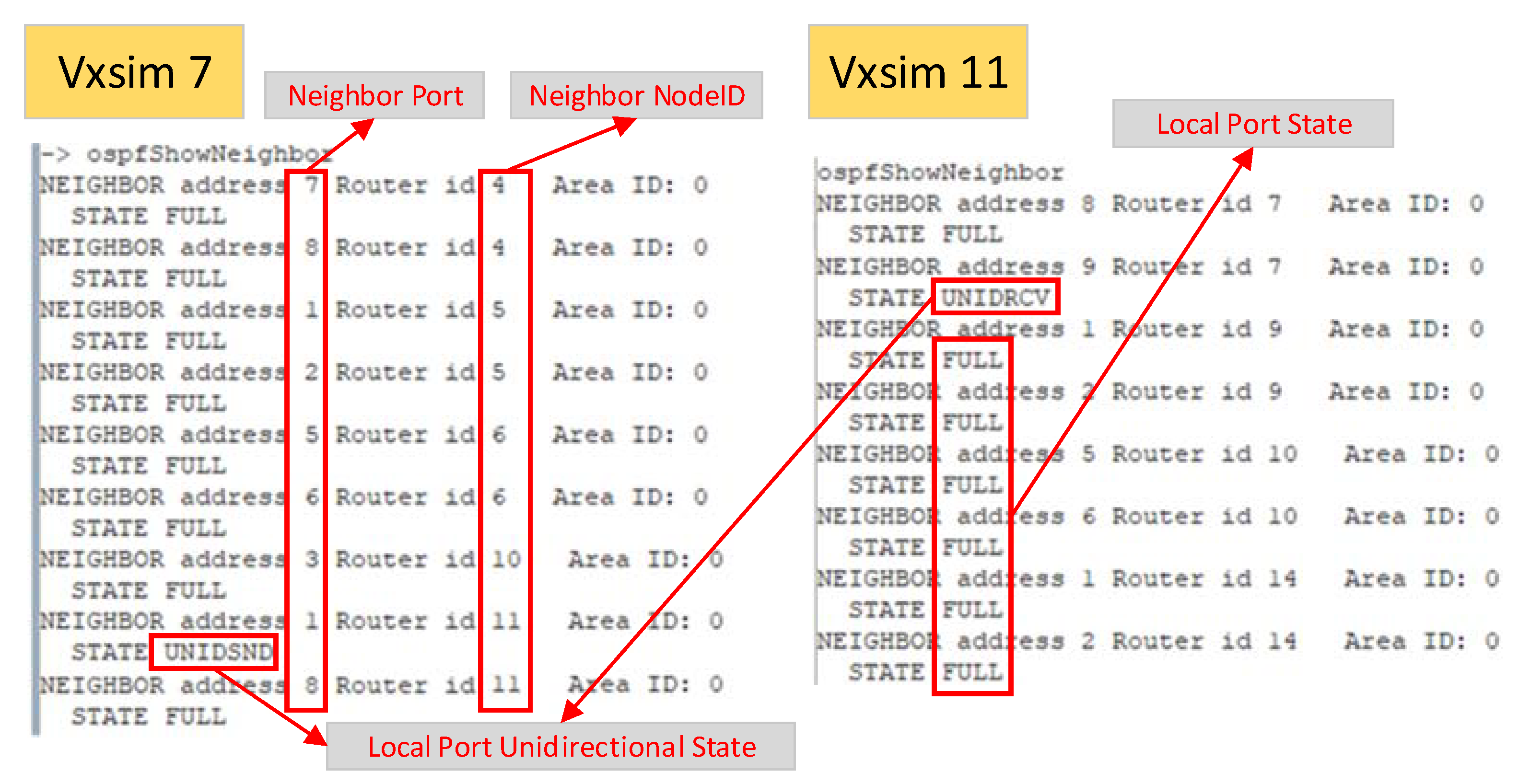
  • Down: in this state, the port sends Hello messages periodically to discover neighbors automatically.
  • Init: when a port has received a Hello message with its own node ID not included, the state changes into this state. In this state, the Hello messages sent by the port include the node ID of the corresponding node.
  • Two-way: when a port has received a Hello message with its own node ID included, the state changes into this state. In this state, the port enters the election of DR (designated router)/BDR (backup designated router), which is only made in a MA (multiple access) network. As the space-based optical backbone network is not an MA network, the election will not be made here. That is to say, this state will change into the next state automatically.
  • Exstart: in this state, the port holds the primary election to confirm the master/slave relationship by sending an empty DD (database description) message with a DD sequence number in it. In the election, the port with a bigger node ID is the master and the other is the slave. The master port leads the exchange of DD messages.
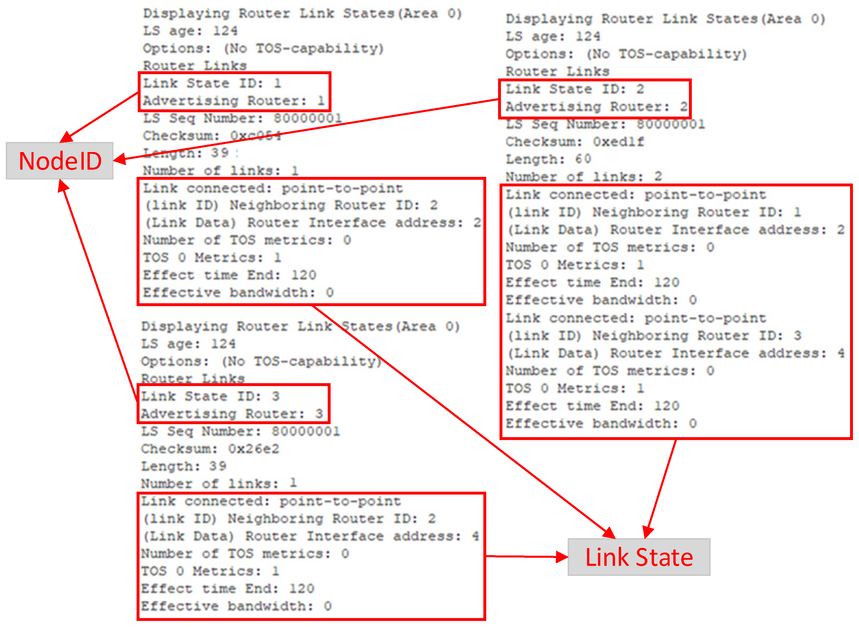
  • Exchange: after the primary election, the port state changes into this state. In this state, the port sends DD messages to exchange description information of the LSDB (link state data base).
  • Loading: after the exchange of DD messages, the port state changes into this state. In this state, the port compares the description of the LSDB received from the correspondent node with its own LSDB to find out if there is any LSA (link state advertisement) which does not exist in its own LSDB. If this is the case, the port sends an LSR (link state require) message including the description of the lacking LSAs to acquire the complete information. Accordingly, when the port of the correspondent node receives the LSR message, it replies with an LSU (link state update) message including the complete information of required LSAs.
  • Full: after the two ports have exchanged all the information of LSAs, the port state changes into this state. This state means that the LSDBs of the two ports have already been synchronized.
  • UnidSnd: this state is added to support the use of unidirectional links. When a port in the full state has received a Hello message with its own node ID not included, the port state changes into this state. In this state, the node where the port is located sends unidirectional messages to the corresponding node, to inform that the link between them is a unidirectional link. In addition, if the port has not received a Hello message within the threshold time (HelloIterval), the node sends NonUnidirectional messages to the corresponding node to inform that the unidirectional link has been broken.
  • UnidRcv: this state is also added to support the use of unidirectional links. When a port in the down state has received a unidirectional message, the port state changes into this state. In this state, the port adds the unidirectional link into the LSDB and sends an LSA to all other nodes to update their LSDBs. In addition, when the port in this state has received a nonunidirectional message, the port state changes into the down state.
The functions of messages mentioned above are defined as follows:
  • Hello Message: used to discover neighbors automatically, including the IDs of its own node and the correspondent node.
  • DD Message: used to exchange the brief description of the LSDB to support the rapid comparison between LSDBs in the two nodes.
  • LSR Message: used to acquire the corresponding node for the complete information of lacking LSAs, which includes a brief description of them.
  • LSU Message: used to send the complete information of the required lacking LSAs to the corresponding node.
  • LSAck Message: used to reply to the LSU message to ensure the reliability of synchronization.
  • Unidirectional Message: added to support the use of the unidirectional links. This is used to inform the information of the unidirectional link to the corresponding node.
  • NonUnidirectional Message: added to support the use of unidirectional links. This is used to inform the corresponding node that the unidirectional link has been broken.
Based on the design mentioned above, the routing protocol can discover neighbors automatically, collect and maintain network resources, and support the use of unidirectional links. The resources collected are stored in an LSDB, which consists of LSAs that are advertised by all nodes in the network. Each LSA describes the link states of a corresponding node. Furthermore, after the collection and maintenance of the network resources, the routing protocol can also use SPF (shortest path first) algorithm to calculate routes. In order to meet more service demands, we added the CSPF (constrained shortest path first) algorithm here, which can calculate the route path under constraints such as bandwidth, path delay and so on. Based on this, the routing protocol can calculate the route path according to the demands of services.

3.1.3. Signal Protocol

The signal protocol is used to build the route path calculated by the routing protocol. It can establish the LSP (label switching path), which transmits services according to labels. We used the CR-LDP (constraint-based routing label distribution protocol) as the signal protocol to build LSPs for services. The label space is based on the platform, where a label is distributed for a destination network segment but not for an interface. In addition, we used a conservative mode to hold labels, which only reserves and maintains the labels used to forward data. Furthermore, according to the demands of protocol stack, we used DoD (distribution on demand) and ordered modes for label distribution and control, which are defined as follows:
  • DoD Mode: used for label distribution, which sends a label mapping message to distribute the label to the upstream node only after having received a label request message from it.
  • Ordered mode: used for label control, which controls the processing of label distribution. It sends a label mapping message to the upstream node, only after having received a label mapping message from the downstream node.
As shown in Figure 6, an LSP consists of a source node, a destination node and several LSRs (label switching routers), which can forward the service data according to the labels distributed by the signal protocol. According to the design of signal protocol, the process of building an LSP is detailed as follows:
  • After the source node has received a requirement to build an LSP, it firstly performs the resource reservation operation. Then, it creates a label request message and sends this to the next downstream node.
  • After the downstream node has received the label request message, it firstly performs the resource reservation operation. Then, the node determines whether it is the destination node.
    • If the result is NO, the node forwards the label request message to the next downstream node.
    • If the result is YES, the node continues to perform the operations of resource utilization and label distribution. In the end, the node creates a label mapping message to the upstream node to notify the label distributed by it.
  • After the upstream node has received a label mapping message, it firstly performs the resource utilization operation. Then, the node determines whether it is the source node.
    • If the result is NO, the node continues to perform the label distribution operation. Then, it creates a label mapping message to the upstream node to notify the label distributed by it.
    • If the result is YES, the node replies with the information of the LSP. By this stage, the LSP has already been built.
The functions of messages and operations mentioned above are defined as follows:
  • Label Request Message: used to require the downstream node to distribute labels to the upstream node.
  • Label Mapping Message: used to send labels distributed by the downstream node to the upstream node.
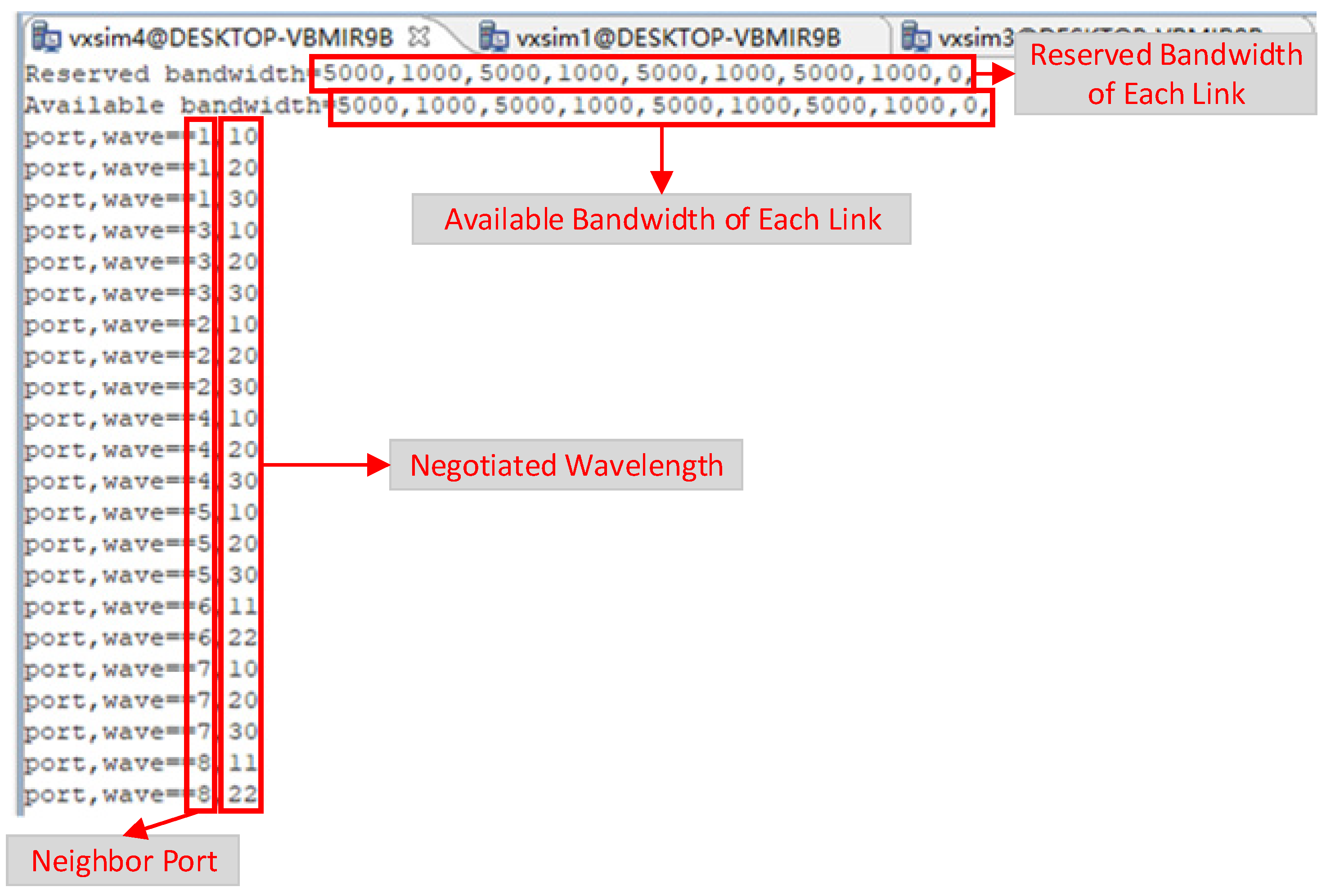
  • Resource Reservation Operation: each link has a special value called RESERVED BANDWIDTH, which is used to record the usage of the link bandwidth by the link management protocol and is not used in the calculation of route path. That is to say, the changes of RESERVED BANDWIDTH do not affect the calculation of route path. So, we used this operation in the first half of processing to build the LSP. This operation deducts the required bandwidth from the RESERVED BANDWIDTH.
  • Resource Utilization Operation: each link has a special value called the AVAILABLE BANDWIDTH, which is used to record the usage of the link bandwidth by the link management protocol and is also used in the calculation of route path. So, changes to the AVAILABLE BANDWIDTH actually affect the calculation of route path. So, we used this operation in the latter half of processing to build the LSP, which deducts the required bandwidth from the AVAILABLE BANDWIDTH.
  • Label Distribution Operation: this operation is used to distribute labels to the LSP.
In order to reduce unnecessary label distributions and table query operations, the signal protocol mechanism inspired by PHP (penultimate hop popping) is used. In the mechanism, the destination node assigns the same specific label(0xffff), which is used in the AOS frames sent by the penultimate hop and tells the downstream node that it is the destination of the path, to the upstream nodes of all LSPs. By doing this, in each LSP, the destination node does not have to distribute a normal label and query the table.
Based on the design discussed above, all protocol massages need to be transmitted in control channels established by the link management protocol. When routing protocol collects network resources, the local resources needed must be collected by link management protocol. In addition, the signal protocol can build LSPs according to the route path calculated by the routing protocol. It can be seen that the three protocols work closely with each other to realize the functions of control plane together.

3.2. Design of Transport Plane
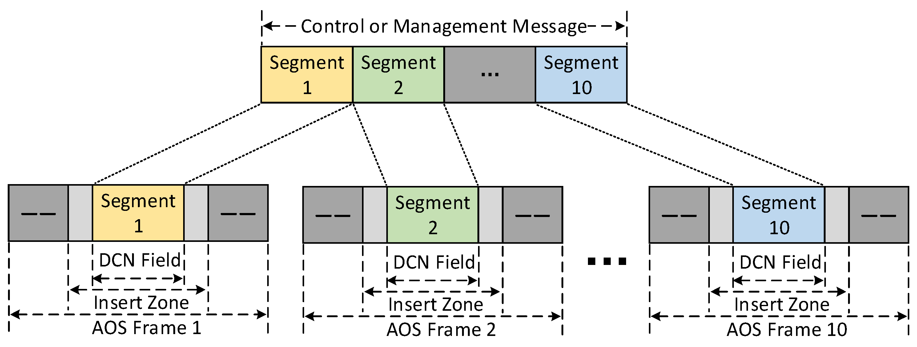
From the design discussed in the architecture of protocol stack, we know that the transport plane should implement functions of control message transmission, data transmission, service adaptation and AOS frame switching.

3.2.1. DCN Channel

In order to realize the functions of control message transmission, we need to use DCN channels. We designed DCN channels by the ECC (embedded communication channel) method.
As shown in Figure 7, we divided the control or management message (fixed length) into ten segments, and then plugged them into the DCN fields in ten continuous AOS frames. The node on the opposite end reads the information from DCN fields and reorganizes them. It can be seen that the DCN channels can provide a stable transmission rate and small delay jitter because of the use of fixed bytes (DCN field) in continuous AOS frames. In addition, DCN channels do not take up the data field, which means that they do not affect the transmission of service data.

3.2.2. Transmission Guarantee

Because of the fact that the inter-satellite optical links in the space-based optical backbone network have no external protection layers that exist in the terrestrial network, they are more likely to be disturbed by factors such as space radiance, particle flow and so on. This affects the stability of transmission in the inter-satellite optical links. Therefore, we designed an ACK(acknowledgement) mechanism to guarantee the transmission of management and control messages in DCN channels. The ACK mechanism is designed as follows:
  • When a node sends any management or control message, it saves the message after it has been sent.
  • When the corresponding node has received the message, it immediately extracts special parameters to create an ACK message and replies it to the corresponding node.
  • Having received the ACK message, the node locates the corresponding message saved previously, and deletes it. If the node has not received the ACK message within a specified timeframe, the node automatically sends the message again.
From the design above, it can be seen that the ACK mechanism effectively avoids the loss of management and control messages caused by the interference in inter-satellite optical links. A similar mechanism could also be designed in an AOS framework to avoid the loss of AOS frames due to the same reason.
As can be seen, the ACK mechanism guarantees the transmission of messages and improves the stability of transmission in inter-satellite optical links.

3.2.3. Service Adaptation

From the design discussed above, we know that the protocol stack builds an LSP for each service to transmit it. So, there is a very important problem here: how to let the service move into its corresponding LSP? The solution is to use a service adaptation method provided by the adaptation module. In the process of building an LSP, the signal protocol has already created an FIB (forwarding information base), which is used to adapt services. Each FIB item includes parameters such as FEC (forwarding equivalence class), OutPort, OutLabel and so on. When a service package arrives, the adaptation module firstly creates the FEC by extracting specific parameters from the package, and then uses the FEC to query the FIB to obtain the corresponding OutPort and OutLabel. Then the protocol stack creates the AOS frame, including the Outlabel and service package, and then sends it through the port specified by OutPort.
In this paper, we completed the adaptation for IPv6 services.
As shown in Figure 8, it can be seen that the IPv6 service adaptation is designed as follows:
  • When an IPv6 package arrives, the adaptation module firstly creates the FEC, in accordance with the rules for extracting the destination address from the package directly as the FEC. Therefore, for the two IPv6 packages shown in the figure, two corresponding FECs (FEC1 and FEC2) was created.
  • Using the FEC created above, the adaptation module then queries the FIB to find out the corresponding OutPort and OutLabel.
  • Having found the OutPort and OutLabel, the adaptation module creates the corresponding AOS frame with its label field filled with the corresponding OutLabel and its data field filled with the corresponding complete IPv6 package.
  • Finally, the adaptation module sends the AOS frame through the port specified by the corresponding OutPort.
By the process designed above, the adaptation module can adapt the IPv6 services in real time. According to the rules of creating an FEC, it can be seen that the adaptation module uses the destination address to differentiate between services, which means all services that go to the same node (with the same address) are adapted into the same LSP. However, the rules can be improved according to the demands of services. If there is a demand for different services to the same node to be differentiated, the adaptation module only needs to improve the rules by extracting more parameters, which can differentiate between the services, to create the FEC. Then, even if the services go to the same node, they are still adapted to the different LSPs according to the improved rules.
As can be seen, the adaptation module could provide service adaptations easy to expand and support the transmission for multiple services.

3.2.4. AOS Frame Switching Scheme

In the CCSDS framework, the AOS Space Data Link Protocol uses a fixed-length PDU (protocol data unit), called an AOS frame, to transmit data. In the traditional scheme, it is impossible to switch the AOS frame directly in an intermediate node without the sign to tell the node where to forward the frame on the current layer. Therefore, even intermediate nodes still have to unpack the AOS frame to obtain the traffic and give it to an upper-layer to perform further processing. After the procession from the upper-layer, the traffic needs to be packed again and forwarded to the specified optical ISL. Data unpacking and packing approaches consume the energy and resources of the node, especially the satellite. In addition, the traditional scheme increases the node processing delay of the AOS frame because the frame cannot be forwarded until the whole procession has been completed. In order to solve these problems, we need to learn from the mature technologies used in terrestrial networks. As we used optical communication to transmit data, the technology of optical packet switching [13] can be considered. However, there are still some processes, such as photoelectric conversion of control messages and processing of the optical signal, that are difficult to implement in the optical packet switching on satellites. As a result, considering the limitations of satellites and the demands of space-based optical backbone network, we used the multiprotocol label switching (MPLS) network [14] as a reference. So, we added a label field in the AOS frame (Figure 2) to carry labels being used to forward AOS frames according to LFIB (label forwarding information base), which includes information such as InLabel, OutPort and OutLabel.
Figure 9 shows the diagram of the AOS frame switching scheme. As can be seen, when an AOS frame arrives at an intermediate node, the node reads the label (if A) located in the label field and queries it in the InLabel column of the LFIB. Having found it, the node then reads the corresponding value of the OutPort (3) and OutLabel (B). Then, the value of the label in the label field is replaced by that of the OutLabel (B), which can be used as the InLabel in the next node, and the AOS frame is then forwarded to the port specified by the value of the OutPort (3). It is clear that the AOS frame switching scheme can switch AOS frames directly in intermediate nodes, which can avoid unnecessary processes, such as unpacking, upper-layer processing and repacking for service traffic to reduce the energy and resource consumption of the intermediate node and decrease the node processing delay of the AOS frame. Furthermore, we can see that only the labels without any information from services are needed to transmit the services. That is to say, the AOS frame switching scheme could provide transparent transmission for services, no matter what type they are.

4. Simulation and Analysis

In conclusion, we have designed a protocol stack that is suitable for a space-based optical backbone network. Next, we simulated it in a simulation software and tested it in a hardware platform, before analyzing the results. Most of the systems used in current satellites of space-based optical backbone networks are based on VxWorks. So, in order to be as close to the actual space environment as possible, we used VxWorks as the system to run the protocol stack, both in the simulation software and hardware platform.

4.1. Simulation in Simulation Software

In order to support the simulation based on VxWorks, we used Wind River Workbench 3.3.6 supporting the system of VxWorks 6.9 as the simulation software to simulate the protocol stack. The software interface is shown as follows:
The simulation software creates the virtual machine running the VxWorks 6.9 system, which is called Vxsim. By using this, we can build a network of Vxsims with VxWorks 6.9 systems installed to simulate the space-based optical backbone network. As shown in Figure 10, we built a network topology of 16 nodes.
As shown in Figure 11, there are 16 nodes with nine ports each in the simulation network. As can be seen, each node has two markers: nodeID and IPv6 Address, which are defined as follows:
  • NodeID: used to mark a node, while managing and controlling the network.
  • IPv6 Address: used to mark a node, while transmitting IPv6 services.
It can also be seen, that there is a unidirectional link from node 11 (0x 000B) to node 7 (0x 0007), which means that data could be transmitted from the former to the latter, but the reverse is not true. Then, we simulated the protocol stack in the simulation network. We ran the protocol stack in each node and then recorded the information shown in the simulation software.

4.1.1. Simulation of Link Management Protocol

First, the link management protocol runs and begins to build control channels and collect local resources. We used node 4 (node 0x 0004) as an example.
Figure 12 shows the local resources collected by the protocol in node 4 (0x 0004), including the bandwidths of the available links and the negotiated wavelengths of available ports which could be used to transmit service data. This means that the link management protocol has built control channels and collected local resources successfully.

4.1.2. Simulation of Routing Protocol

After the establishment of control channels, the routing protocol began to run. After a series of message interactions—specified in the routing protocol—each node had collected the resources of the whole network in its LSDB. As the LSDBs in nodes are the same, we only need to show an LSDB in any one of the nodes, as follows:
From the design discussed in routing protocol, we know that an LSDB consists of LSAs advertised by all nodes in the network. We know that the simulation network has 16 nodes. So, as shown in Figure 13, the LSDB also has 16 LSAs in it, each of which describes the link states of corresponding node. Because an LSA has many links and is usually long, the figure only shows one link state in each LSA. In addition, considering the unidirectional link from node 11 to node 7, we can also observe the neighborhoods of two nodes
In Figure 14, it can be seen that the routing protocol has already collected the link states of two nodes, including the states for the unidirectional link. It is shown that port 9 of node 7 and port 1 of node 11 have entered the state of UNIDSND and UNIDRCV, respectively, which both belong to unidirectional state. These two states mean that the link from port 1 of node 11 to port 9 of node 7 is available, but the reverse is not true, which is exactly what is set in the topology shown in Figure 11.
As can be seen, the routing protocol has collected the resources of the whole network and supported the use of unidirectional links successfully.

4.1.3. Simulation of Protocol Stack

Next, we simulated the functions of protocol stack by building an LSP in the network. First, we used network manager to send a request to build an LSP.
As shown in Figure 15, the request message will be sent to node 1, requiring the node to build an LSP with a bandwidth of 1100 M to the node with the destination address of fe80:0:0:000b::. According to the topology shown in Figure 11, we found that the destination node has a node ID of 11 (0x 000B). Having received the LSP request, the routing protocol first calculates the route path meeting the bandwidth requirement from node 1 to node 11. Then, the signal protocol builds the LSP according to the route path.
Figure 16 shows the label distribution of the signal protocol. It can be seen that the route path consists of nodes 1, 4, 7 and 11. According to the topology of the simulation network, the route path obviously meets the bandwidth requirement of the LSP. This means that the routing protocol can indeed calculate the route path meeting requirement of the bandwidth. The figure also shows FIB or LFIBs that are created by the signal protocol. It is clear that the information of the FIB or LFIBs is accurate and the LSP has already been built by the signal protocol.
Based on the simulation and analysis above, it can be seen that the protocol stack has successfully implemented the previously designed functions.

4.2. Test in Hardware Platform

In order to make the test results more accurate, we built a hardware platform to test the functions of protocol stack.
As shown in Figure 17, the hardware platform is composed of components such as CPU(central processing unit), FPGA(field programmable gate array), computer, and interface, the functions of which are defined as follows:
  • CPU: a place where the protocol stack runs. It implements the functions of the control plane and processing of the management message.
  • FPGA: for control and management, this should support the functions of DCN (Figure 5). For service, this is divided into two types:
    • Adapter FPGA: used only in source/destination node of a path. It can transform different data (bit stream or IP packet) into AOS frames and plug the label into the label field according to the FIB at the source node. Additionally, it can also transform AOS frames into corresponding services at the destination node.
    • Switch FPGA: used to switch AOS frames by their labels according to local LFIBs.
  • Computer: composed of three computers. Two of them are used as sources to create and process services. The other is used as the network manager to manage the platform through Ethernet interface of node 1.
  • Interface: divided into three kinds:
    • Ethernet Interface: used between network manager and node 1 (CPU) to transport the management messages.
    • Serial Interface: used between the CPU and FPGA in each node, transmitting control and management messages.
    • LVDS Interface: used between different FPGAs to transport AOS frames by using LVDS (low-voltage differential signaling).
Based on the architecture designed above, we used a combination of adapter FPGA, switch FPGA and CPU as the source/destination node. Additionally, a pair of CPU and switch FPGAs was used as one intermediate node (node 2). Then, we built the hardware platform as follows:
Based on the hardware platform shown in Figure 18, we downloaded the protocol stack to the system installed in the hardware by using the simulation software. Then, we ran the protocol stack, tested the functions of protocol stack and analyzed the results.

4.2.1. Test of Link Management Protocol

When the protocol stack runs, the link management protocol firstly builds control channels and collects local resources.
As shown in Figure 19, we could see that each node has collected its local resources by the link management protocol.

4.2.2. Test of Routing Protocol

Next, nodes interact with each other and collect resources of the whole network by routing protocol.
As shown in Figure 20, there are three LSAs in the LSDB, each of which is advertised by a node in the network. It can be seen that the LSDB has collected all resources in the network of three nodes.

4.2.3. Test of DCN Channel

We used the network manager to configure an LFIB to the corresponding intermediate node and observed the results. The configuration screen for the LFIB on the network manager is shown in Figure 21.
As shown in Figure 21, it could be seen that this LFIB is configured to node 2. According to the hardware platform architecture (Figure 17), we know that node 1 connects to node 2 through port 2. So, we monitored port 2 of node 1 and captured the results after configuration of network manager.
Figure 22 shows the sequence diagram of ten continuous AOS frames captured by port 2 of node 1. For the convenience of display, it mainly shows part of each AOS frame including the whole DCN field. As can be seen, the management message configured above has already been divided into ten segments and plugged into the DCN fields of ten continuous AOS frames sent by port 2 of node 1. The key values which are configured in the LFIB in the network manager can also be seen. It is clear that DCN channels has already been implemented to transmit management and control messages.

4.2.4. Test of AOS Frame Switching Scheme

Node 2 also connects to node 1 through port 2 (Figure 17). Therefore, node 2 should receive services from port 2 and then forward these to port 4, according to the LFIB with the OutPort of 4 (Figure 21). So, we monitored port 2 and port 4 of node 2 and captured AOS frames.
Figure 23 shows the sequence diagram of the same AOS frame captured by port 2 and port 4 of node 2. As can be seen, the AOS frame was received by port 2 with the INLABEL of 0x 0201 (Figure 23a) and then sent by port 4 with the OUTLABEL of 0x 0301 (Figure 23b). Referring to the LFIB configured in the network manager (Figure 21), we could see that the label in the AOS frame was replaced and the AOS frame was forwarded to port 4, according to the LFIB. That is to say, the AOS frame switching scheme is feasible and well implemented. It can be seen that for an IPv6 service, the only information needed to transmit the service is the labels, which are irrelevant to any information of the service itself. That is to say, the AOS frame switching scheme can indeed provide transparent transmission for services.
Similarly, we can configure all the FIBs/LFIBs of the LSP (label switching path) to the corresponding nodes and built a static LSP by using the network manager.

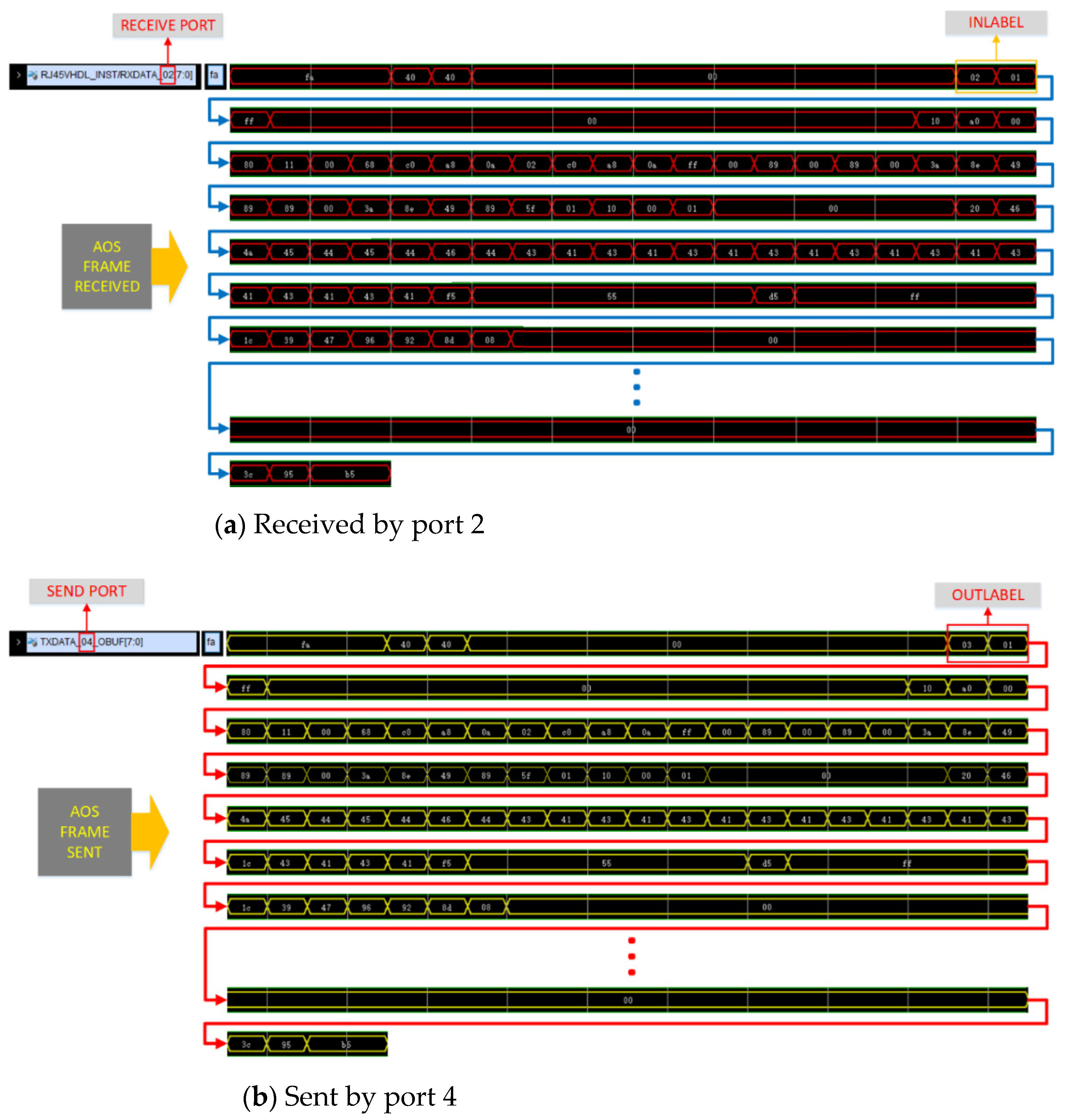
4.2.5. Test of Protocol Stack

In previous work, we tested the functions of each part of the protocol stack. Next, we tested the whole protocol stack by automatically building an LSP. Additionally, we used IPv6 services to test the transmission of the services in the built LSP. We designed a scheme using PING(packet internet groper) services (only IPv6).
Figure 24 shows the scheme for the PING service (only IPv6). According to the scheme, we used two service sources that kept sending PING packages. Then, we used network manager to send a request for building an LSP.
As shown in Figure 25, the network manager sent a request to build an LSP with the destination address of fe80:0:0:30::. According to the hardware platform architecture shown in Figure 17, source 2 has the address and it connects to node 3 directly. So, the LSP should be from node 1 to node 3. Then, the routing protocol calculated the route path and signal protocol built the LSP according to the route path.
As shown in Figure 26, the calculated route path consists of 3 nodes: node 1, 2 and 3. In addition, the signal protocol has already built the LSP by distributing the FIB to node 1 and the LFIB to node 2. Similarly, we used the network manager to build another LSP from node 3 to node 1. Then, two-way LSPs were built for the service and used to track the results.
Figure 27 shows the transmission state of services in the hardware. When one port has received the service data, the corresponding light then lights up, by which we could track the transmission state of services in the hardware in real time. In the Figure 27, the two-way LSPs have already been built and we could see that there are two lights on each FPGA lighting up, which represent the accepting state of the corresponding port. By tracking this, we marked out the transmission state of services in the hardware, as shown in Figure 27. Here, we used a marker to represent a port, for example the marker 2-1 means the port 1 of node 2. Following the arrows marked in the figure, we could see the whole transmission path of services in the hardware platform. Finally, we could see that the services had been transmitted successfully, whose transmission state used to be “Request timed out” before.
Based on the results from the simulations and tests operated above, we can see that the protocol stack was well designed and implemented to realize the functions designed.

5. Conclusions

This paper proposed a protocol stack that is suitable for a space-based optical backbone network. Then, we used software to simulate this protocol stack, built a hardware platform to test it, and finally analyzed the results.
The results showed that the proposed protocol stack was well designed to provide efficient control and management for the space-based optical backbone network. It could improve the management efficiency by collecting resources, calculating and building the route path automatically. It could also facilitate data forwarding in the intermediate satellite nodes with limited source and power, by using the AOS frame switching scheme to avoid unnecessary processes, such as unpacking, upper-layer processing and repacking for passing services. Additionally, it supported the use of unidirectional links to improve the link resource utilization. Finally, it could also provide transparent transmission for different kinds of services.

Author Contributions

Conceptualization, Y.Z. and Y.Y.; methodology, Y.Z. and B.G.; software, M.J., Y.W., M.F. and Y.L.; validation, Q.L., B.Z. and W.Z.; resources, B.W. and S.H.; writing—original draft preparation, Y.Z.; writing—review and editing, B.G.; supervision, B.G.; project administration, Y.Z. All authors have read and agreed to the published version of the manuscript.

Funding

This research was funded in part by National Key R&D Program of China (2018YFB1801702); NSF of China (61622102, 61771074); State Key Laboratory of Advanced Optical Communication Systems Networks.

Institutional Review Board Statement

Not applicable.

Informed Consent Statement

Not applicable.

Acknowledgments

We acknowledge the support given by Huada Gong, Liang Meng and Yaoqi Wang during the project.

Conflicts of Interest

The authors declare no conflict of interest. The funders had no role in the design of the study; in the collection, analyses, or interpretation of data; in the writing of the manuscript, or in the decision to publish the results.

References

  1. Wang, Z.H.; Fu, W.; Chen, W.X. Optical inter-satellite links technique. Opt. Technol. 2003, 29, 669–674. [Google Scholar]
  2. Lindgren, N. Optical communications—A decade of preparations. Proc. IEEE—Special Issue Opt. Commun. 1970, 58, 1410–1421. [Google Scholar] [CrossRef]
  3. Chan, V.W.S. Optical satellite networks. J. Lightwave Technol. 2003, 21, 2811–2827. [Google Scholar] [CrossRef]
  4. Chan, V.W. Free-space optical communications. IEEE/OSA J. Lightwave Technol. 2006, 24, 4750–4762. [Google Scholar] [CrossRef]
  5. Karafolas, N.; Baroni, S. Optical satellite networks. J. Lightwave Technol. 2000, 18, 1792–1806. [Google Scholar] [CrossRef]
  6. Chan, S.; Chan, V.W.S. Constellation topologies for a space-based information network backbone using optical inter-satellite links. In Proceedings of the IEEE MILCOM 2004, Military Communications Conference, Monterey, CA, USA, 31 October–3 November 2004. [Google Scholar]
  7. Chen, W.; Zhang, X.; Deng, P.; Gong, Y.; Wu, H. RSN: A space-based backbone network architecture based on space-air-ground integrated network. In Proceedings of the IEEE 9th International Conference on Communication Software and Networks (ICCSN), Guangzhou, China, 6–8 May 2017. [Google Scholar]
  8. Li, T.T.; Guo, H.X.; Wang, C.; Wu, J. Optical Burst Switching based Satellite Backbone Network. In Proceedings of the 4th Seminar on Novel Optoelectronic Detection Technology and Application, Nanjing, China, 24–26 October 2017. [Google Scholar]
  9. AOS Space Data Link Protocol; CCSDS 732.0-B-3, Blue Book; CCSDS: Washington, DC, USA, 2015.
  10. Huang, S.G.; Guo, B.L.; Yuan, Y.B.; Wang, B.; Zhang, Y.; Yang, H.; Jiang, M.; Wang, Y.; Fu, M.; Liu, Y. Control and Management of Optical Inter-Satellite Network based on CCSDS Protocol. In Proceedings of the 46th European Conference on Optical Communication (ECOC), Brussels, Belgium, 6–10 December 2020. [Google Scholar]
  11. IP over CCSDS Space Links; CCSDS 702.1-B-1, Blue Book; CCSDS: Washington, DC, USA, 2012.
  12. ITU-T Study Group 15. Architecture for the Automatically Switched Optical Network. ITU-T G.8080. 2012. Available online: www.itu.int/ITU-T/recommendations/rec.aspx?rec=11515&lang=en (accessed on 6 March 2021).
  13. Eramo, V.; Listanti, M. Input Wavelength Conversion in Optical Packet Switches. IEEE Commun. Lett. 2003, 7, 281–283. [Google Scholar] [CrossRef]
  14. Rosen, E.; Viswanathan, A.; Callon, R. Multiprotocol Label Switching Architecture. IETF RFC 3031. 2001. Available online: www.rfc-editor.org/info/rfc3031 (accessed on 6 March 2021).
Figure 1. Protocol stack model. CCSDS: Consultative Committee for Space Data Systems
Applsci 11 02367 g001
Figure 2. Expanded advanced orbiting systems (AOS) frame structure. DCN: data communication network; OAM: operation, administration and maintenance.
Applsci 11 02367 g002
Figure 3. Functions of three planes.
Applsci 11 02367 g003
Figure 4. Internal logical relationship of each plane.
Applsci 11 02367 g004
Figure 5. State machine of signal protocol.
Applsci 11 02367 g005
Figure 6. Processing of Building an label switching path (LSP).
Applsci 11 02367 g006
Figure 7. Data communication network (DCN) Channel.
Applsci 11 02367 g007
Figure 8. IPv6 service adaptation.
Applsci 11 02367 g008
Figure 9. Advanced orbiting systems (AOS) frame switching scheme diagram. LFIB: label forwarding information base.
Applsci 11 02367 g009
Figure 10. Simulation software interface.
Applsci 11 02367 g010
Figure 11. Topology of the simulation network.
Applsci 11 02367 g011
Figure 12. Local resources collected by link management protocol in node 4 (0x0004).
Applsci 11 02367 g012
Figure 13. Link state data base (LSDB) in one of the nodes in simulation network.
Applsci 11 02367 g013
Figure 14. Neighborhoods of node 7 and node 11.
Applsci 11 02367 g014
Figure 15. Network manager screen for LSP request in simulation network.
Applsci 11 02367 g015
Figure 16. Label distribution of the signal protocol in simulation network.
Applsci 11 02367 g016
Figure 17. Hardware platform architecture. LVDS: low-voltage differential signaling.
Applsci 11 02367 g017
Figure 18. Hardware Platform.
Applsci 11 02367 g018
Figure 19. Local resource collected by the link management protocol in all nodes.
Applsci 11 02367 g019
Figure 20. LSDB in One of the Nodes.
Applsci 11 02367 g020
Figure 21. Network manager configuration screen for LFIB.
Applsci 11 02367 g021
Figure 22. DCN Sequence Diagram.
Applsci 11 02367 g022
Figure 23. Sequence diagram of AOS frame captured by port.
Applsci 11 02367 g023
Figure 24. Scheme for PING Service (Only IPv6).
Applsci 11 02367 g024
Figure 25. Network manager screen for LSP request in hardware platform.
Applsci 11 02367 g025
Figure 26. Label distribution of the signal protocol in hardware platform.
Applsci 11 02367 g026
Figure 27. Service transmission demonstration.
Applsci 11 02367 g027
Publisher’s Note: MDPI stays neutral with regard to jurisdictional claims in published maps and institutional affiliations.

