Article

UKF-Based State Estimation for Electrolytic Oxygen Generation System of Space Station

1
School of Automation Science and Electrical Engineering, Beihang University, Beijing 100191, China
2
China Academy of Aerospace Standardization and Product Assurance, Beijing 100071, China
*
Author to whom correspondence should be addressed.
Appl. Sci. 2021, 11(5), 2021; https://doi.org/10.3390/app11052021
Submission received: 25 August 2020 / Revised: 16 October 2020 / Accepted: 22 October 2020 / Published: 25 February 2021
(This article belongs to the Section Aerospace Science and Engineering)

Abstract

:
Electrolytic oxygen generation system (EOGS) is the only system that can provide oxygen for astronauts in a physicochemical regenerative way in a long-term manned spacecraft. In order to ensure that the astronauts in the cabin can obtain a continuous and enough oxygen supply, it is necessary to carry out real-time condition monitoring and fault diagnosis of the EOGS. This paper deals with condition monitoring and fault diagnosis of the EOGS. Firstly, the dynamic model of the system is established based on the principle electrolysis for actual oxygen production system and the state observer of the system has been designed by using unscented Kalman filter (UKF). The total pressure in the cabin and the partial pressure of oxygen in the electrolytic cell can be observed. Then, considered the actual conditions of the manned space mission with one more astronaut, i.e., 3 astronauts, the simulation experiment is carried out. The simulation results show that the method can effectively estimate the system state, and it is of great significance to ensure the normal operation of the electrolytic EOGS system in the space station.

1. Introduction

Electrolytic oxygen generation (EOGS) is currently recognized as the most reasonable oxygen replenishment technology for the space station [1,2,3,4]. It is one of the core technologies of the physical and chemical regenerative environmental control and life support system (ECLSS) [5,6,7], and it is also the key technology for realizing long-term manned space flight [8]. The status of EOGS directly determines the oxygen content in the enclosed cabin with astronauts during the orbit [9]. Because the cargo spaceships between the space and earth can’t be launched deliberately at any time, EOGS must guarantee the high reliability and ECLSS will open the carried oxygen bottle to supply oxygen to the astronauts [10] when EOGS fails to produce oxygen. Since the oxygen carried during each launch is limited, and as the oxygen is gradually consumed, the oxygen content in the cabin will continue to decline, which not only affects the normal work of the astronaut, but also poses a serious threat to the life of the astronaut [11,12]. The electrolytic oxygen plant of the International Space Station (ISS) developed by the United States was put into formal use after being verified in the orbit. In 2002, the main oxygen system of ISS completely stopped working after a few weeks of intermittent work, and the three astronauts on the station had to use the solid fuel oxygen tank to produce oxygen [13] before the main oxygen system was repaired. In 2004, due to the blockage of the pipeline, the main oxygen system failed again, the two astronauts inside had to rely on the oxygen in the docking cargo tank to maintain their lives, meanwhile waiting for the Russia cargo to transfer more oxygen [14]. Seen from the abovementioned events, it is necessary to monitor the working state and to diagnose the fault of the electrolysis oxygen system of the space station [15,16,17].
At present, different technical solutions are adopted for the EOGS system by the US and Russian space stations. The two countries are very disparate in terms of their design ideas, resource requirements, system configuration and service life. The biggest difference is that Russia adopts the solution for EOGS by flow alkaline electrolyte and membrane static water gas separator. Russia conducted flight verifications of the EOGS device at the early stage of the construction of the Mir space station, and then directly installed the station as the main oxygen supply equipment. In the initial stage of the construction of the International Space Station, the Russian electrolytic oxygen plant was used as the main oxygen supply equipment. The technical scheme of solid polymer electrolyte (SPE) used in EOGS of United States was officially put into use after on-orbit verification, meeting the oxygen demand of the International Space Station. The use of EOGS has greatly reduced the amount of ground logistics supplies for life insurance, and is one of the necessary conditions for medium and long-term manned spaceflight. Russia uses alkaline electrolyzer PEM. Russian electrolytic oxygen generator uses strong corrosive lye as the electrolyte, it has caused great difficulties in on-orbit maintenance and replacement of parts [18]. The US electrolytic oxygen generator in the ISS adopts the technical solution of solid polymer electrolyte (SPE) water electrolysis [19], and the US electrolytic oxygen generator adopts a standard cabinet-style installation method to facilitate on-orbit maintenance and replacement. The EOGS in China’s future space station adopts the same method as the United States. The background of this study is China’s long-term manned space mission, and the technical scheme of SPE is used in EOGS [20].
In long-term manned missions, the oxygen concentration in the cabin of the space station can be detected by the detection device in real time [21,22]. However, the oxygen concentration in the cabin is not suitable as a standard for judging whether the EOGS system is operating normally, due to the particularity of the space station. Given the backgrounds of irregular connection of multi-cabin sections, the large space capacity, and the uncertain metabolic activities of many astronauts, the O2 concentration in the capsule is a slowly changing parameter, the response speed of which is very slow [23]. Under such conditions, the concentration of hydrogen and oxygen at the outlet of the EOGS system can be used as direct indicator parameters for online monitoring. The reason is that the concentration of hydrogen and oxygen at the outlet are parameters that can be directly selected. However, electrolytic core, as the core equipment of the electrolytic oxygen system, because of its complicated structure and small space, the working condition inside of which is known with difficulty. Many parameters of electrolytic core, such as the direct oxygen production amount and the working efficiency, cannot be directly measured. If accurate location of the system faults is required, especially the faults that occur inside the electrolytic core, the limited data measured by the sensor will be insufficient, such as the total pressure in the cabin and the partial pressure of oxygen in the cabin. In order to solve this issue, a system state observer needs to be designed. As one kind of improved Kalman filer, Unscented Kalman filter (UKF) can be widely used in the design of the state observer because it can approximate the probability density distribution of nonlinear state variables. Instead of approximating the nonlinear function, it uses a series of deterministic samples to approximate the posterior probability density of the state variables. Compared with extended Kalman filter (EKF), neither the derivative calculation of Jacobian matrix is required [24,25], nor the higher-order terms are ignored during linearization, and thus the calculation accuracy of nonlinear distribution statistics is higher than EKF [26,27,28]. In addition, Yang et al. studied the health management of metal roof structure [29], Li et al. conducted multi-factor analytic hierarchy process [30], and Sheng et al. carried out multi-objective optimization for power system [31], all of these researches have the important reference significance for health management of the space station system.
In this paper, according to the operating conditions of the actual system, and the operating mechanism and conditions of the key equipment and the entire system, a mathematical model that can describe the dynamic changes of the parameters is established, and then the nonlinear state observer of the system is designed by UKF to monitor the state of the system and diagnose fault. The most important task is to perform condition monitoring and fault diagnosis for the electrolytic core. It is also under consideration to locate and diagnose the faults of other main components including pipelines and steam separators. Thus, various abnormalities or failures of the EOGS system can be timely and accurately diagnosed, prevented and eliminated. Reliability, safety, and effectiveness of equipment operation can be improved. In this way, the possible failure loss of the system can be reduced to the lowest level.
The structure of this paper is as follow: firstly, the function, working process and working principle of the EOGS in the physical and chemical regenerative environment control and life support system of the space station are described in detail. Then, according to the previous correlation analysis, the kinetic model of oxygen production system is established. Then, a state observer based on UKF algorithm is designed. At last, a simulation experiment is designed with one more astronaut than the Chinese space laboratory TG-2. The experimental results show the accuracy of the model is good and the effectiveness of the state estimation scheme is valid.

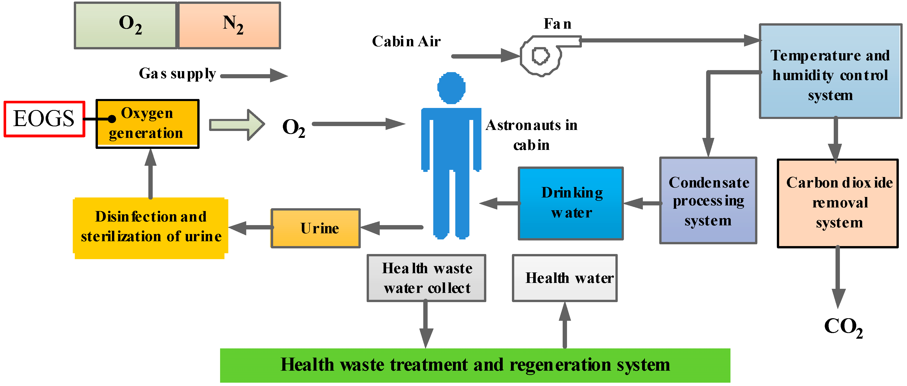
2. Operation Analysis and Working Principle of EOGS

EOGS is one of the essential core systems of ECLSS in long-term manned mission. From the perspective of energy conversion, the EOGS converts the input electrical energy into heat and chemical energy, and the input deionized water is reacted to generate hydrogen and oxygen, as well as un-electrolyzed water. Therefore, the dynamic model of the actual system can be established by analyzing the processes and principles of the material and energy exchange of the actual system.

2.1. Operation Analysis of EOGS

The role and working process of the electrolytic oxygen system in the environmental control life insurance system are shown in Figure 1. During the operation of the space station’s ECLSS, the EOGS receives materials from the urine treatment system and the water treatment system, generates deionized water after certain treatment, and then uses electricity to electrolyze the deionized water to generate oxygen and provide it for the astronauts in the cabin. If there are some faults in the electrolytic oxygen system and oxygen supply is insufficient, astronauts are required to promptly open the redundancy spare oxygen cylinders in the space station to continue supplying oxygen for them.
The specific work flow of EOGS is shown in Figure 2. The specific operation process of the whole system is that the electrolytic water first enters the circulating water storage tank, and then enters the electrolytic core after being pressurized by the circulating pump together with the water that was not completely electrolyzed in the last time. The circulating pump plays a role in providing fixed flow water for the electrolytic core. The electrolysis of water by the electrolytic core has certain electrolysis efficiency. Only a part of the electrolytic water can produce electrolysis reaction in unit time, generating oxygen and hydrogen, and generating water vapor due to the reaction heat. The other part of water changes into water vapor. It carries the electrolysis heat and oxygen from the anode to leave the electrolysis unit. Then, after the heat exchanger completes the heat exchange, it is separated from the hydrogen at the water gas separator. The oxygen gas enters the cabin, and the water enters the circulating water storage tank. The hydrogen generated by the reaction carries a small amount of water and heat away from the cathode. After heat exchange, it needs to be separated with water and then discharged from the tank. The separated water also needs to enter the circulating water storage tank for reuse. The core component of the oxygen production system of space station is the electrolytic core, which is composed of several electrolytic cells described above. The whole oxygen production system is composed of circulating water tank, water vapor separator, pipeline and other components. The water source of the electrolyzed oxygen production equipment includes human metabolic water, mainly urine. Since the battery of the electrolysis oxygen production system can provide stable direct current, the direct power supply of the electrolysis oxygen production system comes from the battery of its own system. The electrolysis oxygen production system is integrated into the space station’s power supply plan as a whole, and the electrolysis battery’s electricity comes from the space station’s power bus. The overall power of the space station comes from PV. Hydrogen production and fuel cells are key technologies to achieve the mutual transformation of hydrogen energy and electric energy. Fuel cell and electrolytic oxygen production can be placed in the same equipment. When the electric energy is sufficient, more electrolytic oxygen production can be carried out to produce hydrogen and oxygen, which can be stored for later use. When electricity is scarce, the electrolysis oxygen production system is turned into a fuel cell system, which uses the reaction of hydrogen and oxygen to generate electricity to charge the electrolysis battery, reducing the dependence on the space station’s electricity.

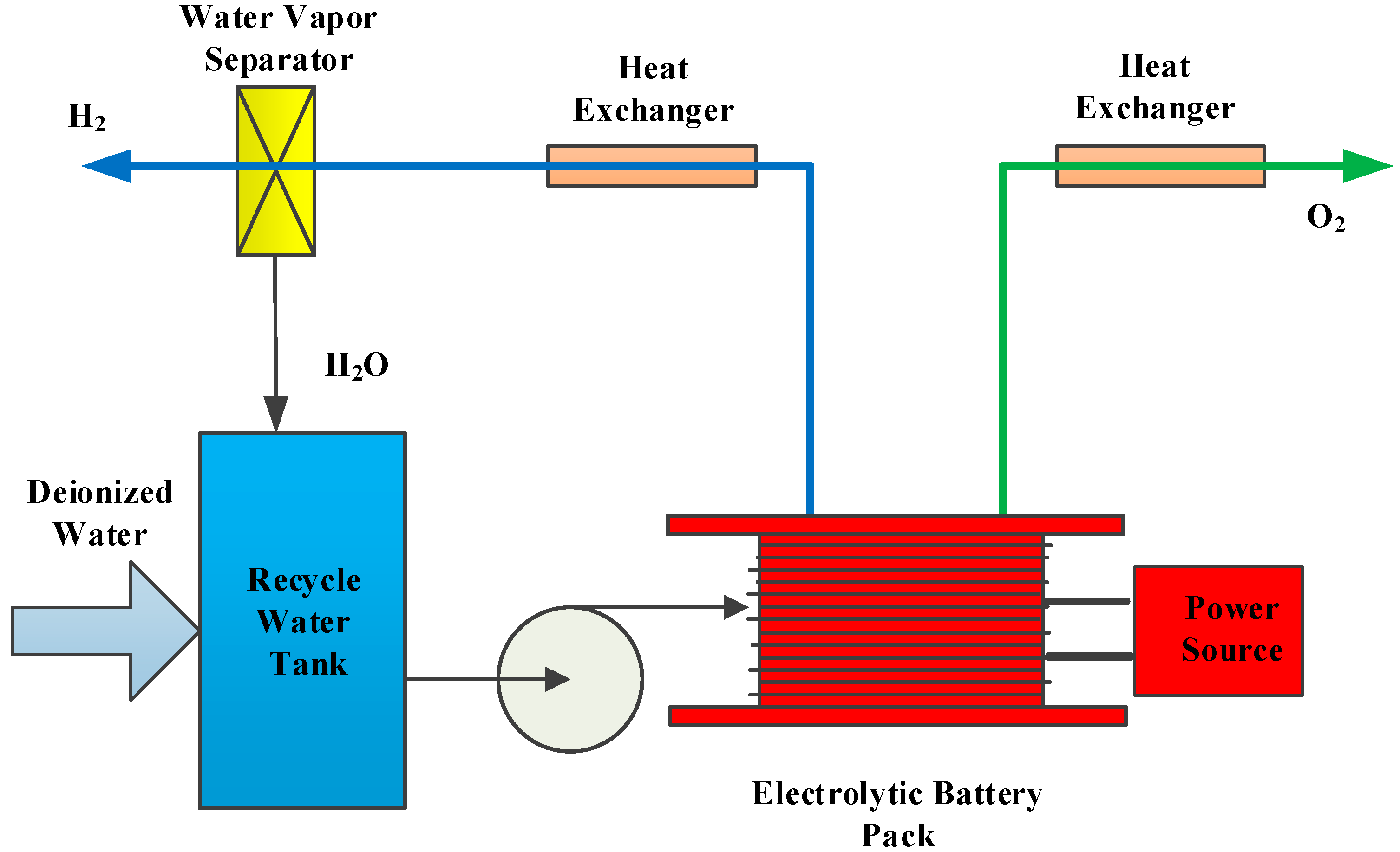
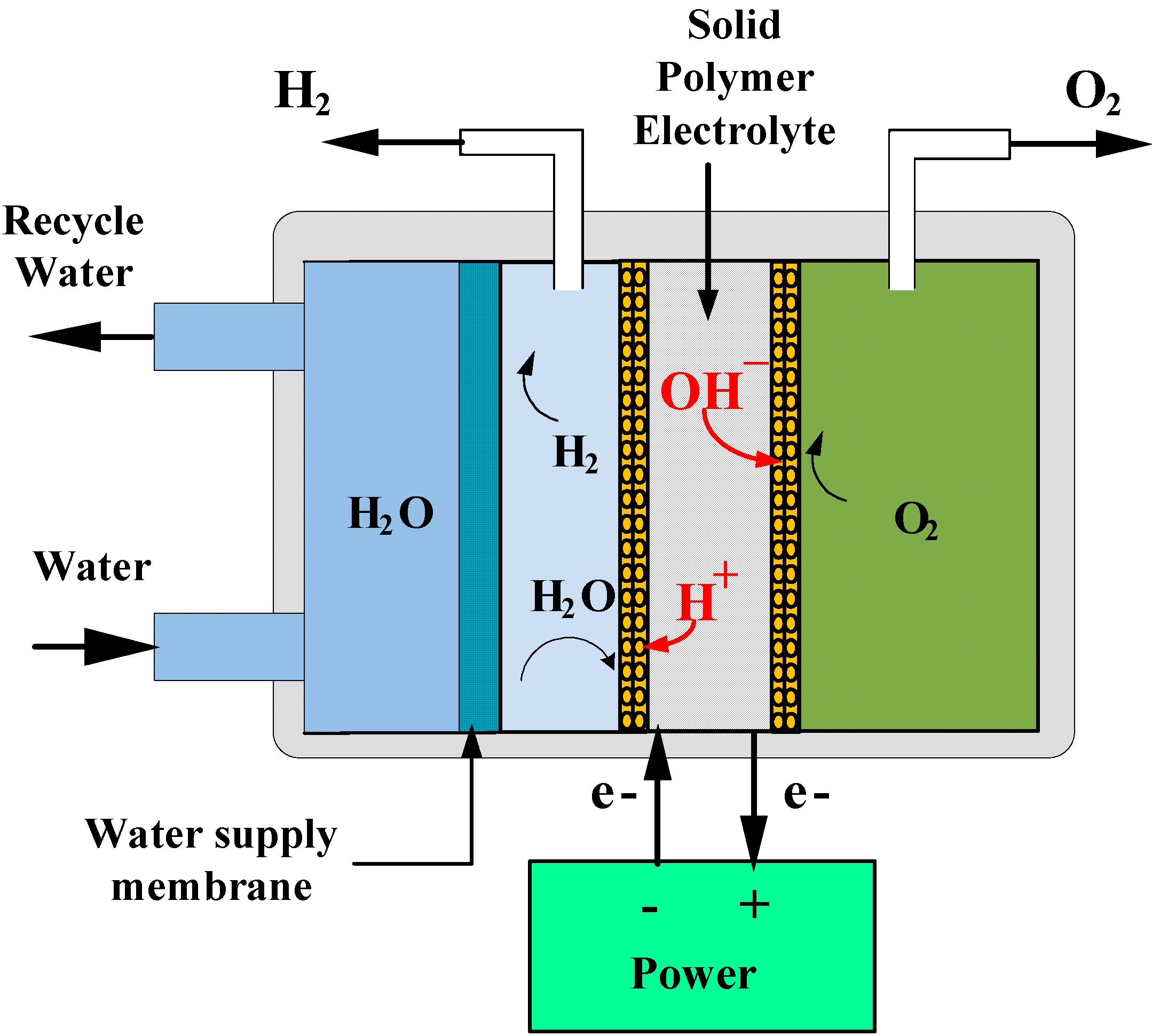
2.2. The Working Principle of EOGS

The basic process of oxygen generation by water electrolysis is that direct current is applied to the electrolyzer body, and water molecules react electrochemically on the electrode to decompose into hydrogen and oxygen.
Cathode reaction:
2 H 2 O + 2 e H 2 + 2 O H
Anode reaction
2 O H 2 e 1 2 O 2 + 2 H 2 O
Total reaction equation:
H 2 O H 2 + 1 2 O 2
The electrolysis of water follows Faraday’s law of electrolysis. The gas output is proportional to the current, and the working current depends on the working voltage, working temperature and electrolyte concentration.
The principle of water electrolysis is also used in the oxygen production system of the space station. However, the solid polymer electrolyte (SPE) is used as the membrane. The SPE is a perfluorosulfonate polymer ion exchange membrane with a thickness of only 0.3 mm and many physical properties of polytetrafluoroethylene. When the SPE is immersed in water, it is a good ionic conductor with good conductivity. It is the only electrolyte required for water electrolysis. Take a schematic diagram of an electrolytic cell, as shown in Figure 3. Two electrodes are connected on both sides of the solid polymer electrolytic membrane to form an anode and a cathode. The conductivity of ions is provided by hydrous ions. Ions are transferred from anode to cathode by solid polymer and ion exchange membrane. Water is fed into the electrolytic cell from the cathode (hydrogen electrode), which simplifies the requirements of water supply system and water gas separation under weightlessness. In order to dissipate heat, the circulating water flow should be greater than the water supply required by electrolysis. Enough water is transported from the hydrogen electrode to the oxygen electrode through the solid-state electrolytic membrane, and the oxygen, hydrogen ions and electrons are discharged by electrochemical decomposition at the oxygen electrode. Hydrogen ions in the cathode are electrochemically reacted to release hydrogen, hydrogen and water are discharged together, and the oxygen produced does not contain free water.
Based on the analysis of the basic principle of EOGS and the working principle of electrolytic cell, it can be assumed that:
  • The oxygen, hydrogen and water vapor in the core are all ideal gases, and the working pressure in the cell will not exceed 150 kPa;
  • Water vapor and water can quickly saturate with oxygen and hydrogen in the mixed gas flow;
  • Hydrogen and oxygen are insoluble in water;
The mass conservation equation of the electrolytic oxygen system is as follows:
q s = q O 2 + q H 2 + q m i x
where q s is the amount of water supplied to the system, kg; q m i x is the flow rate of water vapor in the mixed flow of hydrogen and water, kg; q O 2 is the oxygen production, kg; q H 2 is the hydrogen production, kg.
According to the basic thermodynamic conservation law, the energy conservation equation of the electrolysis oxygen system is as follows:
N = Q O 2 + Q H 2 + Q E + Q O 2 e x + Q H 2 e x + Q H 2 S e p + Q m i x H 2 + Q c o l d + Q H 2 O q H 2 O
where Q H 2 O = P H 2 O q H 2 O ; P H 2 O = 1.588 × 10 7 J / kg .
According to the basic thermodynamic conservation law, the mass conservation and energy conservation equations of the electrolytic core are as follows:
q w c = q O 2 + q H 2 + q n e
N C = Q C + Q w C + Q O 2 C + Q H 2 C + Q O 2 w + Q H 2 w + Q H 2 O q H 2 O
where, Q W C is the heat taken away from the outlet of the electrolytic cell, Q C is the heat taken away by the water discharged from the electrolytic core, Q O 2 C and Q H 2 C are respectively the heat removed by oxygen and hydrogen, Q O 2 w and Q H 2 w are the heat taken away by anode water vapor and cathode water vapor. Their calculating formulas are as follows:
Q W C = ( q p q O V q H V q O 2 q H 2 ) c p ( T C O T C I )
Q C = K c F C ( T C T A )
Q O 2 C = q O 2 c p O 2 ( T C O T C I )
Q H 2 C = q H 2 c p H 2 ( T C O T C I )
Q O 2 w = q O 2 w [ c p ( T C O T C I ) + λ ]
Q H 2 w = q H 2 w [ c p ( T C O T C I ) + λ ]

3. The Dynamic Model of EOGS

The whole process and principle of EOGS is analyzed above. The mass exchange relationship of the EOGS is simple, but the heat exchange relationship is great intricate, and it also has a complex coupling relationship with ECLSS’s other systems. The most important thing is that the heat value in the heat exchange process is difficult to measure and calculate accurately. In order to reflect the problem more clearly and intuitively, the functional block diagram of the EOGS in the space station can be simplified as shown in Figure 4, in which two valves are valve_O2 and valve_H2 is a back pressure valve, and the water vapor separator is a membrane separator.
In long-term manned missions, the cabin’s oxygen partial pressure and total pressure need to be monitored. Therefore, it is necessary to establish the state equation of these two state quantities.
State equation of cabin’s oxygen partial pressure is written as:
P O 2 c a b i n · = R a T c M O 2 V c w O 2 c a b i n
State equation of cabin’s total pressure is written as:
P t c a b i n · = R a T c M a i r V c ( w O 2 c a b i n + w N 2 c a b i n + w C O 2 c a b i n )
The core index reflecting the state of the core is the electrolytic efficiency of the core, which can be reflected by the oxygen and hydrogen production. Due to its small volume and complex internal structure, it is impossible to install sensors to measure the oxygen and hydrogen production. However, the electrolytic core’s oxygen production and hydrogen production can be used as state variables of the system. The hydrogen and oxygen production volume of the electrolytic core can be obtained through the establishment of the state equation of oxygen production and hydrogen production and the design of the system state observer.
The established equations of state for oxygen production and hydrogen production are as follows:
P H 2 E · = R a T e M H 2 ( V s + V e ) ( w H 2 E w H 2 c a b i n )
P O 2 E · = R a T e M O 2 V e ( w O 2 E w O 2 c a b i n )
where V e = 1.29 m 3 ; V s = 0.29 m 3 .
According to Figure 4, Valve_O2 and Valve_H2 are back pressure valves, and the w O 2 c a b i n and w H 2 c a b i n in Equations (16) and (17) are as follows:
w O 2 c a b i n = 2 ρ o 2 C d 1 A o 1 β 1 P O 2 E P t c a b i n
w H 2 c a b i n = 2 ρ H 2 C d 2 A o 2 β 2 P H 2 E
where C d 1 = 0.01 ; C d 2 = 0.002 ; A 01 = 0.08 ; A 02 = 0.01 β 1 = 1 ; β 2 = 1 .
According to Faraday’s law, the production of oxygen and hydrogen can be obtained as follows:
w O 2 E = M O 2 I n c 2 F z
w H 2 E = M H 2 I n c F z
where n c = 24 ; F = 9.65 × 10 4 / 3600 Ah/mol; z = 2 .
Selecting [ P ˙ O 2 c a b i n , P ˙ t c a b i n , P ˙ H 2 E , P ˙ O 2 E ] T as the state variables of the system, i.e., x = [ P ˙ O 2 c a b i n , P ˙ t c a b i n , P ˙ H 2 E , P ˙ O 2 E ] T = [ x 1 , x 2 , x 3 , x 4 ] T , the state equation of the system can be obtained as follows:
{ P ˙ O 2 c a b i n = R a T c M O 2 V c w O 2 c a b i n P ˙ t c a b i n = R a T c M a i r V c ( w O 2 c a b i n + w N 2 c a b i n + w C O 2 c a b i n ) P ˙ H 2 E = R a T e M H 2 ( V s + V e ) ( w H 2 E w H 2 c a b i n ) P ˙ O 2 E = R a T e M O 2 V e ( w O 2 E w O 2 c a b i n )
It can be found from the Equation (24) that the P O 2 E has no direct relationship with factors such as the length of the system running time and the number of astronauts.
Substituting Equations (14)–(17) into Equation (22), and the coefficients can be defined as following:
k 11 = R a T c M O 2 V c , k 12 = 2 ρ o C d 1 A o 1 β 1 , k 21 = R a T c M a i r V c , k 22 = R a T c M a i r V c ( w N 2 c a b i n + w C O 2 c a b i n ) , k 31 = R a T c M H 2 ( V s + V e ) , k 32 = 2 ρ H 2 C d 2 A o 2 β 2 , k 41 = R a T c M o V e
The state equation of the EOGS can be written as follows:
{ x ˙ 1 = k 11 k 12 ( x 4 x 2 ) x ˙ 2 = k 21 k 12 ( x 4 x 2 ) + k 22 x ˙ 3 = k 31 ( M h I n c F z k 32 x 3 ) x ˙ 4 = k 41 [ + M o 2 I n c F z k 12 ( x 4 x 2 ) ]
The system observation equation is as follows:
y = ( x 1 , x 2 ) T + v t
where v t R 2 × 1 is the zero mean Gaussian white noise, E ( v t v t T ) = R t R 2 × 2 .

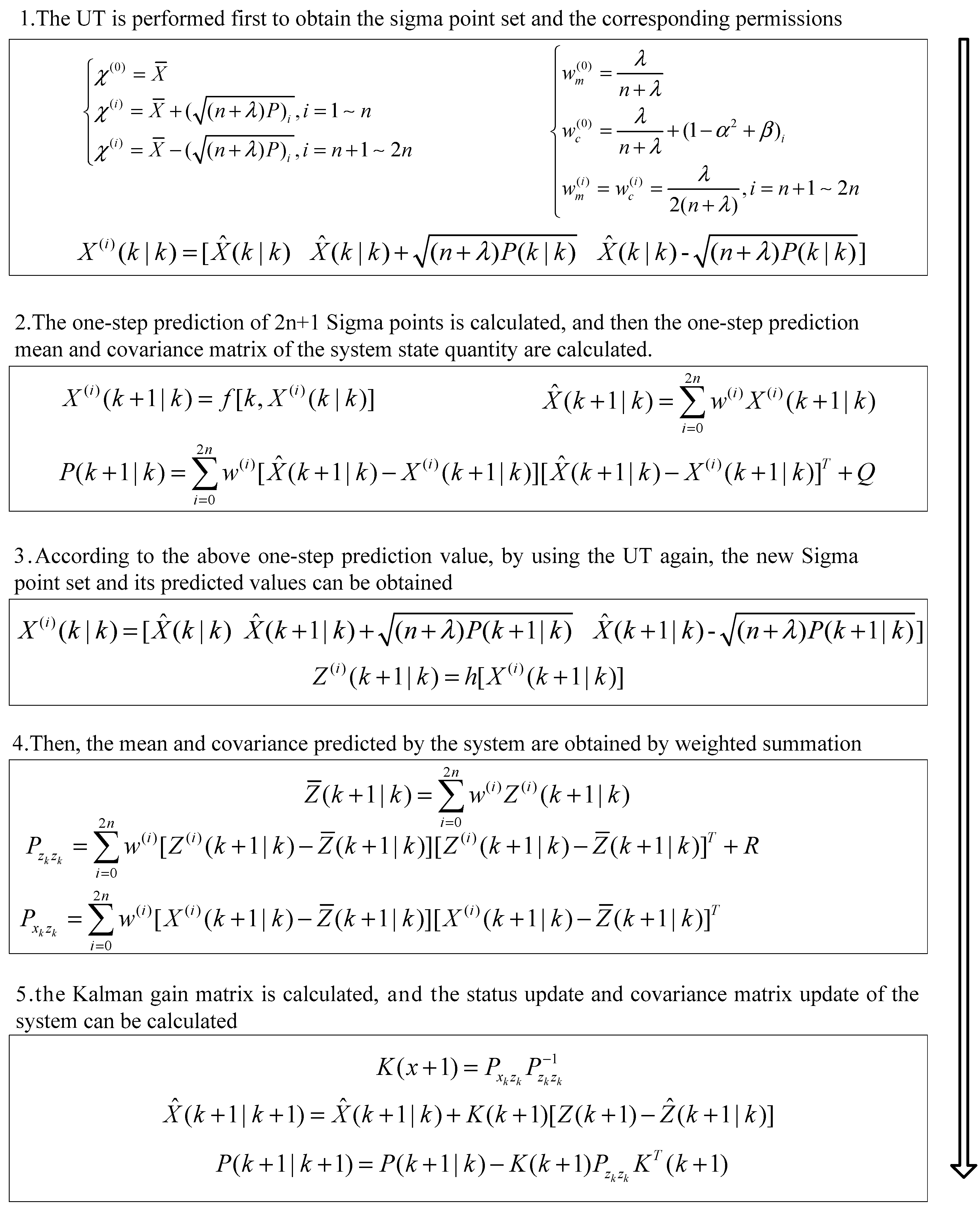
4. State Monitoring of EOGS Based on UKF

The state equation of the system has been determined, so the four states of the system can be estimated on-line by using the observation values of oxygen partial pressure and total pressure in the cabin. The condition monitoring and fault prediction of the two key components of the electrolytic core and the water gas separation device are carried out by two states of the internal pressure of the oxygen chamber of the electrolytic core and the downstream back pressure of the water gas separator. Therefore, the system state observer based on UKF filter algorithm can be designed. UKF algorithm does not need forced linearization, but uses unscented transform (UT) to make the mean and covariance of sampling points equal to the mean and covariance of the original state distribution. By using UT, the accuracy is at least 2-order Taylor expansion, and 3-order accuracy can be achieved when the system noise is Gaussian distribution. For different time k, the nonlinear system composed of random variable X with Gaussian white noise W(k) and observation Z with Gaussian white noise V(k) can be described as follows:
{ X ( k + 1 ) = f ( x ( k ) , W ( k ) ) Z ( k + 1 ) = h ( x ( k ) , V ( k ) )
The specific process of UKF algorithm are shown in Figure 5.
According to the steps of the UKF algorithm, the state equation and observation equation of EOGS, i.e., Equations (24) and (25), are iteratively operated according to the method in Figure 5, and the partial pressure and total pressure in the cabin can be obtained by real-time estimation of oxygen.

5. Simulation Results

The simulation of monitoring the status of the EOGS is carried out according to the actual operating conditions of the space station on orbit. During orbiting, there are usually three astronauts in the space station. The overall cabin capacity is 150 m3, the electrolytic temperature in the electrolytic cell is 35 °C, the temperature in the cabin is 25 °C, the electrolytic current is 20 A, and the orbital situation of Tiangong 2 is 2 people and 30 days. We set the simulation test as 3 people and 30 days (720 h), which is in line with the actual situation of the long-term stay of the space station.
As shown in Figure 6, the estimated value of the total pressure in the cabin can track the real value well, almost coincident with the real value. The enlarged picture shows the comparison between the real value and the estimated value of the total pressure in the cabin on the 20th day of the system operation.
As shown in Figure 7, the estimation error of UKF based cabin total pressure is shown. The estimation error of the total pressure in the cabin is tiny, and the amplitude of the positive and negative values does not change great. The estimation error does not exceed 2% of the true value, which not only shows the high accuracy of the model, but also shows that the accuracy of the UKF estimation is high. which not only shows the high accuracy of the model, but also shows the high accuracy of UKF estimation.
Figure 8 shows that the comparison between the true value of the oxygen partial pressure in the cabin and the estimated value based on UKF. As seen from Figure 8, there are periodic increases in estimation errors over the time, but these increases take place during the working condition switching of electrolysis current (5 A to 10 A), therefore there is the larger error between the true value and the estimation value during the working stage of 10A electrolysis current. During the working stage at 5 A electrolysis current within 30 days, the estimation error is small and the estimated value of the oxygen partial pressure in the cabin can also track the real value well. In Figure 8, the enlarged picture also shows the comparison between the real value and the estimated value of the oxygen partial pressure in the cabin on the 20th day of the system operation.
As shown in Figure 9, the estimation error of oxygen partial pressure in the cabin based on UKF. The estimation error of the oxygen partial pressure in the cabin has little change in the range of positive and negative values, and it will increase periodically, but the estimation error is less than 2%.

6. Conclusions

Based on the principle analysis and system dynamics of the EOGS, the mathematical model to describe the dynamic characteristics of EOGS is established. On this basis, the UKF based state observer is designed. The simulation experiment is carried out under the condition of setting the same actual working condition as China’s tiangong-2, with one more astronaut compared with scheduled 2 astronauts. The main conclusions are as follows:
  • The established dynamic model of the system is relatively simple and accurate. It can be used for the simulation experiment of EOGS, avoiding the complex coupling relationship between the system and other systems caused by energy exchange.
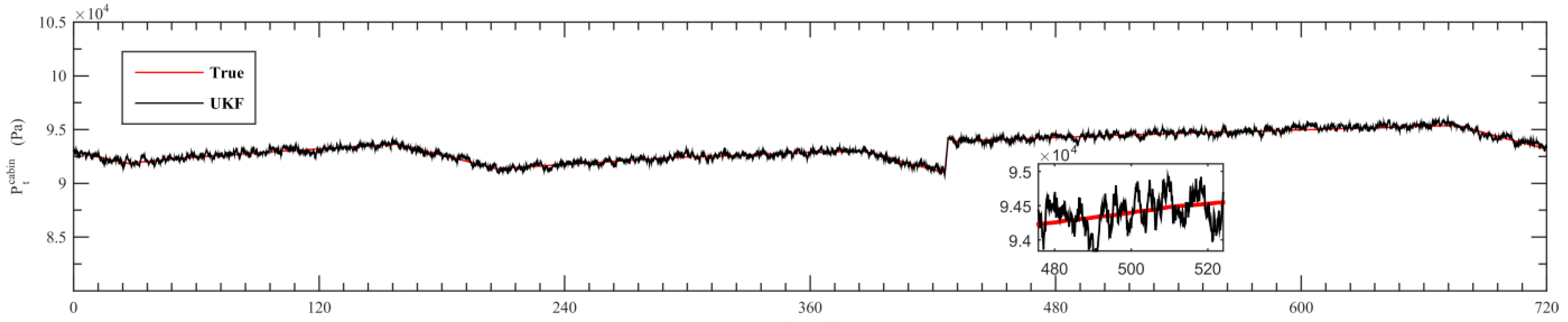
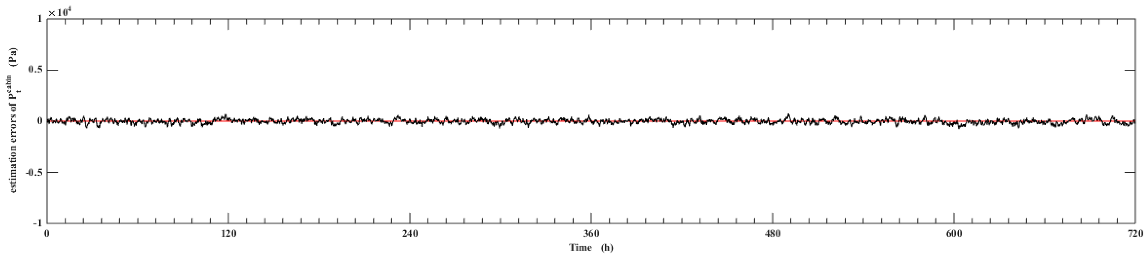
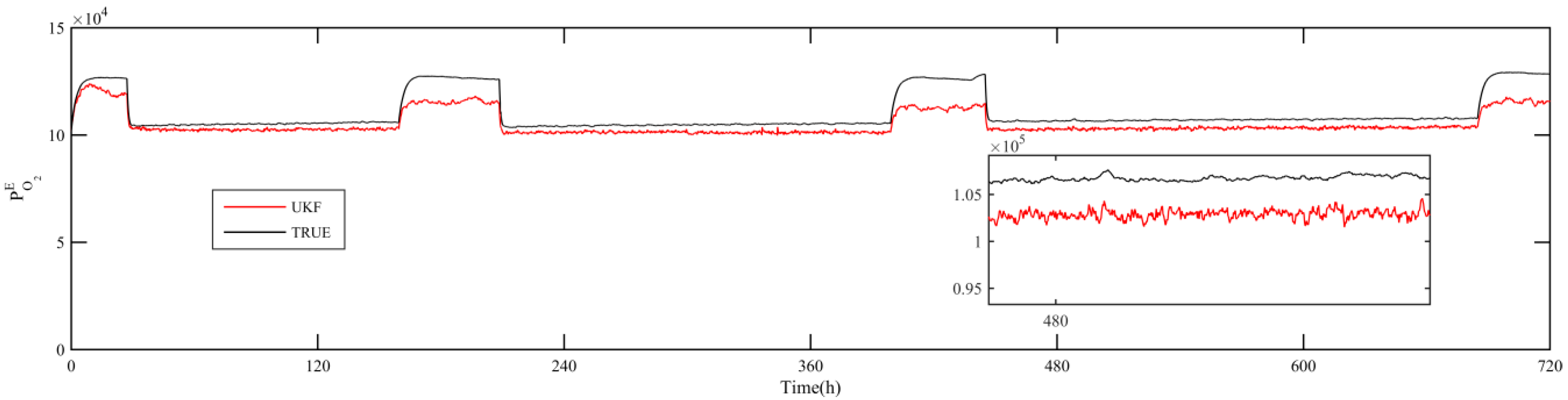
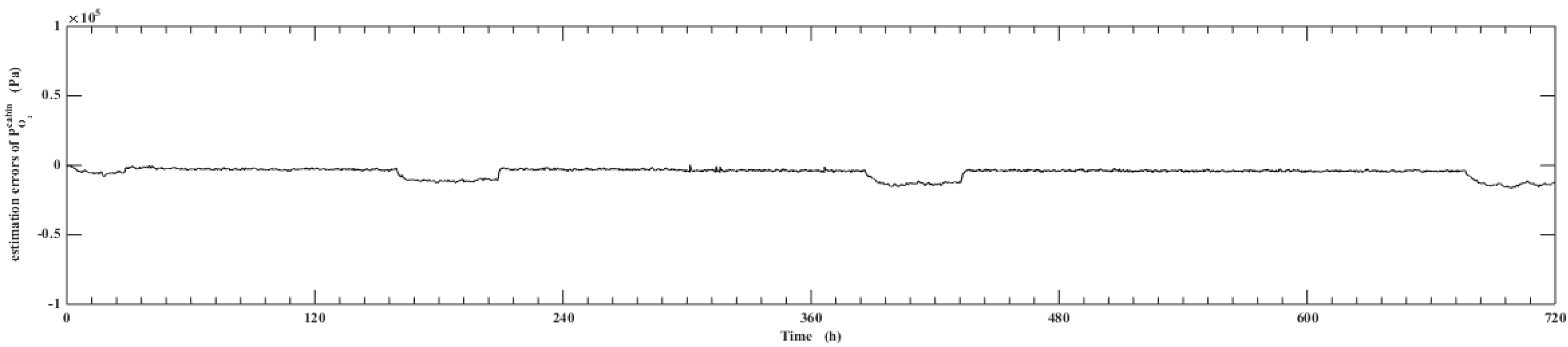
  • Using UKF algorithm to design the observer the state of the system can achieve a high accuracy. The estimation error of the system state is within 2% by comparing the estimation value with the real value.
  • The model and UKF algorithm built in this paper can monitor the state of the system, and diagnose the fault of the core components based on actual observation values simultaneously, which will lay a solid foundation for the subsequent comprehensive fault diagnosis of the EOGS.

Author Contributions

Writing—original draft, M.L.; conceptualization, M.L. and Y.L.; methodology and software, M.L.; funding acquisition, X.L.; supervision and project administration, X.L.; writing—review and editing, Y.L. and W.Z.; testing of existing code components, R.G.; data curation, R.G.; All authors have read and agreed to the published version of the manuscript.

Funding

This research was funded by Pre-research project in the manned space filed of China grant number 050403.

Institutional Review Board Statement

Not applicable.

Informed Consent Statement

Not applicable.

Data Availability Statement

The data presented in this study are available on request from the corresponding author.

Conflicts of Interest

The authors declare no conflict of interest.

Nomenclature

q s amount of water supplied to the systemkg
q m i x flow rate of water vapor in the mixed flow of hydrogen and waterkg
q H 2 hydrogen productionkg
N input power of the system and are the heat carried by oxygen and hydrogenJ
Q O 2 , Q H 2 heat carried by oxygen and hydrogenJ
Q E electrolysis cellJ
Q O 2 e x , Q H 2 e x , Q H 2 e x heat dissipated to the environment by the oxygen heat exchanger, the hydrogen heat exchanger, and the water-gas separator, respectivelyJ
Q m i x H 2 heat carried by water vapor in the mixed flow of hydrogen and waterJ
Q H 2 O q H 2 O theoretical power consumption of electrolyzed waterJ
Q c o l d heat taken away by the cold mass through the heat exchangerJ
Q H 2 O theoretical power consumption required for water electrolysisJ
P H 2 O theoretical power consumption per unit mass of water electrolysisJ/kg
q H 2 O mass of water being electrolyzedkg
q w c mass of water entering the electrolytic corekg
q n e mass of water discharged from the cathodekg
Q W C heat taken away from the outlet of the electrolytic cellJ
Q C heat taken away by the water discharged from the electrolytic coreJ
K c heat dissipation coefficient of the electrolytic cell to the environmentJ/(m·℃)
F C total heat dissipation length of the electrolyzerm
T C temperature of the electrolytic cell
T A ambient temperature
Q O 2 C heat removed by oxygenJ
Q H 2 C heat removed by hydrogen respectivelyJ
q O 2 w , q H 2 w mass flow rate of water vapor carried by the cathode and anode respectivelykg/s
T C I , T C O inlet and outlet temperature of the electrolytic core respectively
Q O 2 w , Q H 2 w heat taken away by anode water vapor and cathode water vaporJ
c p , c p O 2 , c p H 2 specific heat capacities of water, hydrogen, and oxygenJ/(kg·°C
λ latent heat of vaporization of waterJ
P O 2 c a b i n oxygen partial pressurekPa
P t c a b i n total pressurekPa
M a i r molar mass of airkg/s
R a Ideal gas constant\
T c temperature in cabin
V c total volume in cabin
w O 2 c a b i n mass flow of oxygen into the cabinkg/s
w N 2 c a b i n the mass flow of nitrogen into the cabinkg/s
w C O 2 c a b i n mass flow of carbon dioxide into the cabinkg/s
P H 2 E hydrogen partial pressure in cellkPa
P O 2 E oxygen partial pressure in cellkPa
M H 2 molar mass of hydrogenkPa
T e temperature in the electrolysis cell
w H 2 E mass flow of hydrogen produced by the electrolysis cellkg/s
w H 2 c a b i n mass flow from electrolysis cell to cabinkg/s
V s volume of water vapor separator cavity
V e volume of chamber in electrolysis cell
w O 2 E mass flow of hydrogen produced by the electrolysis cellkg/s
C d 1 , C d 2 Valve_O2’s flow coefficient and Valve_H2’s flow coefficient respectivelyKv
A 01 , A 02 Valve_O2’s valve area m2
β 1 , β 2 Valve_H2’s flow coefficient, valve area and opening respectively\
I electrolysis currentA
n c number of single cells in the electrolysis system\
F Faraday constantAh/mol
z amount of charge\

References

  1. Jerng, L.; Jeng, F. Modeling and Test Data Analysis Of The Life Support System Integration Facility Oxygen Generation Subsystem. SAE Tech. Paper Ser. 1995, 104, 1139–1152. [Google Scholar] [CrossRef]
  2. Grigoriev, G.Y.; Lagutin, A.S.; Nabiev, S.; Zuev, B.; Filonenko, V.; Legin, A.; Kirsanov, D. Water quality monitoring during interplanetary space flights. Acta Astronaut. 2019, 163, 126–132. [Google Scholar] [CrossRef]
  3. Anderson, M.; Sargusingh, M. Evolution of environmental control and life support system requirements and assumptions for future exploration missions. In Proceedings of the 47th International Conference on Environmental Systems, Charleston, South Carolina, 16–20 July 2017. [Google Scholar]
  4. Stapleton, T.J.; Heldmann, M.; Schneider, S.; O’Neill, J.; Samplatsky, D.; White, K.; Corallo, R. Environmental Control and Life Support for Deep Space Travel. In Proceedings of the 46th International Conference on Environmental Systems, Vienna, Austria, 10–14 July 2016. [Google Scholar]
  5. Sharma, G.; Rai, R.N. Reliability modeling and analysis of environmental control and life support systems of space stations: A literature survey. Acta Astronaut. 2019, 155, 238–246. [Google Scholar] [CrossRef]
  6. Williams, D.E.; Dake, J.R.; Gentry, G.J. International Space Station Environmental Control and Life Support System Status: 2009–2010. In Proceedings of the 40th International Conference on Environmental Systems, Barcelona, Spain, 11–15 July 2010; pp. 2010–6180. [Google Scholar]
  7. Malin, J.; Kowing, J.; Schreckenghost, D.; Bonasso, P.; Nieten, J.; Graham, J.; Fleming, L.; MacMahon, M.; Thronesbery, C. Multi-agent diagnosis and control of an air revitalization system for life support in space. In Proceedings of the 2000 IEEE Aerospace Conference. Proceedings (Cat. No.00TH8484), Big Sky, MT, USA, 25 March 2002; Volume 6, pp. 309–326. [Google Scholar]
  8. Boscheri, G.; Lavagna, M.; Lamantea, M. Multidisciplinary Preliminary Sizing of Advanced Life Support Systems for Space. SAE Tech. Paper Ser. 2009. [Google Scholar] [CrossRef]
  9. Grigor’Iev, G.; Lagutin, A.S.; Nabiev, S.; Vasiliev, A.; Orlov, O.; Mukhamedieva, L.; Pakhomova, A.; Rodin, A.; Semenov, V.; Stavrovskii, D.; et al. Atmosphere composition control during long-duration space missions. Acta Astronaut. 2019, 163, 112–119. [Google Scholar] [CrossRef]
  10. Schneider, W.F.; Gatens, R.L.; Anderson, M.S.; Broyan, J.; Macatangay, A.; Shull, S.; Perry, J.; Toomarian, N. NASA environmental control and life support technology development and maturation for exploration. In Proceedings of the 46th International Conference on Environmental Systems, Vienna, Austria, 10–14 July 2016. [Google Scholar]
  11. Gentry, G.J. International Space Station (ISS) Environmental Control and Life Support (ECLS) System Overview of Events: 2015–2016. In Proceedings of the 46th International Conference on Environmental Systems, Vienna, Austria, 10–14 July 2016. [Google Scholar]
  12. Guo, R.; Li, Y.; Lv, M. Design of infinite sliding mode state observer with application to CO2 absorption system of space station. Acta Astronaut. 2019, 161, 579–587. [Google Scholar] [CrossRef]
  13. Brewster, H.S. International Space Station: Its history challenges and successes. In Proceedings of the 40th Aerospace Sciences Meeting & Exhibit, Reno, NV, USA, 6–9 January 2003. [Google Scholar]
  14. Popov, A.; Fink, W.; Hess, A. “PHM for Astronauts” Project to Run on the International Space Station: The Status and Plan Forward. In Proceedings of the 2019 IEEE Aerospace Conference, Big Sky, MT, USA, 2–9 March 2019; pp. 1–12. [Google Scholar]
  15. Hu, W.; Wu, Q.E.; Zou, J. Research on Automatic Fault Diagnosis of Environmental Control and Life Support Systems. J. Comput. Theor. Nanosci. 2014, 11, 1394–1402. [Google Scholar] [CrossRef]
  16. Li, Y.; Lv, M.; Ling, L.; Yang, L.; Li, D.; Dong, S.; Li, Y. Analysis of atmospheric circulation for physicochemical regenerative environment control and life support system in space station. In Proceedings of the 2016 IEEE International Conference on Advanced Intelligent Mechatronics (AIM), Banff, AB, Canada, 12–15 July 2016; pp. 1491–1496. [Google Scholar]
  17. Lv, M.; Li, Y.; Liu, W.; Guo, R.; Yang, L.; Pang, L.; Li, Y.; Wang, J. Development of simulation platform for physicochemical regenerative environment control and life support system in space station. In Proceedings of the 2016 IEEE 11th Conference on Industrial Electronics and Applications (ICIEA), Hefei, China, 5–7 June 2016; pp. 1145–1150. [Google Scholar]
  18. Samsonov, N.M.; Kurmazenko, E.A.; Gavrilov, L.I.; Farafonov, N.S.; Pavlova, N.V.; Pavlova, T.N.; Proshkin, V.J.; Romanov, S.J.; Rjabkin, A.M.; Guzenberg, A.S.; et al. Operation Results Onboard the International Space Station and Development Tendency of Atmosphere Revitalization and Monitoring System. SAE Tech. Paper Ser. 2004, 1. [Google Scholar] [CrossRef]
  19. Kurmazenko, E.A.; Samsonov, N.M.; Gavrilov, L.I.; Farafonov, N.S.; Belavencev, J.E.; Pavlova, N.V.; Proshkin, V.J.; Romanov, S.J.; Geleznyakov, A.G.; Ryabkin, A.M.; et al. Off-normal Situations Related to the Operation of the Electron-VM Oxygen Generation System aboard the International Space Station. In Proceedings of the International Conference on Environmental Systems, Rome, Italy, 11–14 July 2005. [Google Scholar]
  20. Wen, H. Tiangong-2 Space Laboratory achieved a number of “first” verifications. J. Aerospace. China 2016, 11, 4–7. (In Chinese) [Google Scholar]
  21. Bernier, M.C.; Alberici, R.M.; Keelor, J.D.; Dwivedi, P.; Zambrzycki, S.C.; Wallace, W.T.; Gazda, D.B.; Limero, T.F.; Symonds, J.M.; Orlando, T.M.; et al. Microplasma Ionization of Volatile Organics for Improving Air/Water Monitoring Systems On-Board the International Space Station. J. Am. Soc. Mass Spectrom. 2016, 27, 1203–1210. [Google Scholar] [CrossRef] [PubMed]
  22. Stuffler, T.; Hofmann, P.; Honne, A.; Witt, J. ANITA2 flight model development—A status report of the multicomponent ISS Air Analyser. In Proceedings of the 47th International Conference on Environmental Systems, Charleston, South Carolina, 16 July 2017. [Google Scholar]
  23. Gentry, G.J. International Space Station (ISS) Environmental Control and Life Support (ECLS) System Overview of Events: 2016–2017. In Proceedings of the 47th International Conference on Environmental Systems, Charleston, South Carolina, 16–20 July 2017. [Google Scholar]
  24. Xie, L.; Zhou, Z.; Zhao, L.; Wan, C.; Tang, H.; Xue, S. Parameter Identification for Structural Health Monitoring with Extended Kalman Filter Considering Integration and Noise Effect. Appl. Sci. 2018, 8, 2480. [Google Scholar] [CrossRef] [Green Version]
  25. Lv, M.-B.; Li, Y.-H.; Guo, R. Galerkin-based extended Kalman filter with application to CO2 removal system. J. Central South. Univ. 2020, 27, 1780–1789. [Google Scholar] [CrossRef]
  26. Han, H.; Wei, Y.; Ye, X.; Liu, W. Motion Planning and Coordinated Control of Underwater Vehicle-Manipulator Systems with Inertial Delay Control and Fuzzy Compensator. Appl. Sci. 2020, 10, 3944. [Google Scholar] [CrossRef]
  27. Yang, J.; Chang, Y.; Gao, T.; Wang, J. Failure Prediction of the Rotating Machinery Based on CEEMDAN-ApEn Feature and AR-UKF Model. Appl. Sci. 2020, 10, 2056. [Google Scholar] [CrossRef] [Green Version]
  28. Zhou, H.; Zhao, H.; Huang, H.; Zhao, X. A Cubature-Principle-Assisted IMM-Adaptive UKF Algorithm for Maneuvering Target Tracking Caused by Sensor Faults. Appl. Sci. 2017, 7, 1003. [Google Scholar] [CrossRef] [Green Version]
  29. Yang, L.; Fu, C.Y.; Li, Y.H.; Su, L.M. Survey and study on intelligent monitoring and health management for large civil structure. Int. J. Intell. Robotics Appl. 2019, 3, 239–254. [Google Scholar] [CrossRef]
  30. Sheng, W.; Liu, K.; Liu, Y.; Meng, X.; Li, Y.H. Optimal Placement and Sizing of Distributed Generation via an Improved Nondominated Sorting Genetic Algorithm II. IEEE Transactions on power delivery. 2015, 30, 569–578. [Google Scholar]
  31. Li, H.; Li, D.; Li, Y.H. A multi-index assessment method for evaluating coverage effectiveness of remote sensing satellite. Chinese J. Aeronautics. 2018, 31, 2023–2033. [Google Scholar] [CrossRef]
Figure 1. The operation of ECLSS in space station.
Applsci 11 02021 g001
Figure 2. The block diagram of EOGS.
Applsci 11 02021 g002
Figure 3. Schematic of electrolytic cell.
Applsci 11 02021 g003
Figure 4. The simplified workflow sketch of EOGS.
Applsci 11 02021 g004
Figure 5. The specific process of UKF algorithm.
Applsci 11 02021 g005
Figure 6. Comparison of true value and estimated value of total pressure in cabin.
Applsci 11 02021 g006
Figure 7. Estimated error of total pressure in cabin.
Applsci 11 02021 g007
Figure 8. Comparison of true value and estimated value of oxygen partial pressure in cabin.
Applsci 11 02021 g008
Figure 9. Estimation error of the partial pressure of oxygen in cabin.
Applsci 11 02021 g009
Publisher’s Note: MDPI stays neutral with regard to jurisdictional claims in published maps and institutional affiliations.

