1. Introduction
Gas foil bearings (GFBs) have been considered as a core lubrication technology for oil-free high-speed rotation machinery [
1]. Bump-type GFBs have compliant sub-structures including a bump and top foil, which improve the load-carrying capacity and rotordynamic stability [
1,
2]. The use of GFBs reduces system complexity and maintenance costs for their simple design [
3,
4]. Major applications of GFBs include high-speed turbomachinery and electro-mechanical machinery such as turbo-compressors, turbo-blower, micro gas turbines, and electric permanent magnet motors/generators.
Specifically, GFBs have the following advantages as compared to conventional rigid hydrodynamic gas bearings [
5]:
High Load Capacity: A compliant bump foil structure increases the minimum thickness region in the gas film, leading to a capability to support higher loads.
Low Power Losses: The prevalence of gas-film thickness results in lower viscous friction losses of the bearing.
High-Speed Operation: Improved damping characteristics caused by the sliding motion between the bump foil and top foil/bearing housing makes the journal rotate stably at high speed.
Self-Alignment: The flexibility of the bearing structure accommodates misalignment of assembled system and vibration/shock, or any other unexpected maneuver.
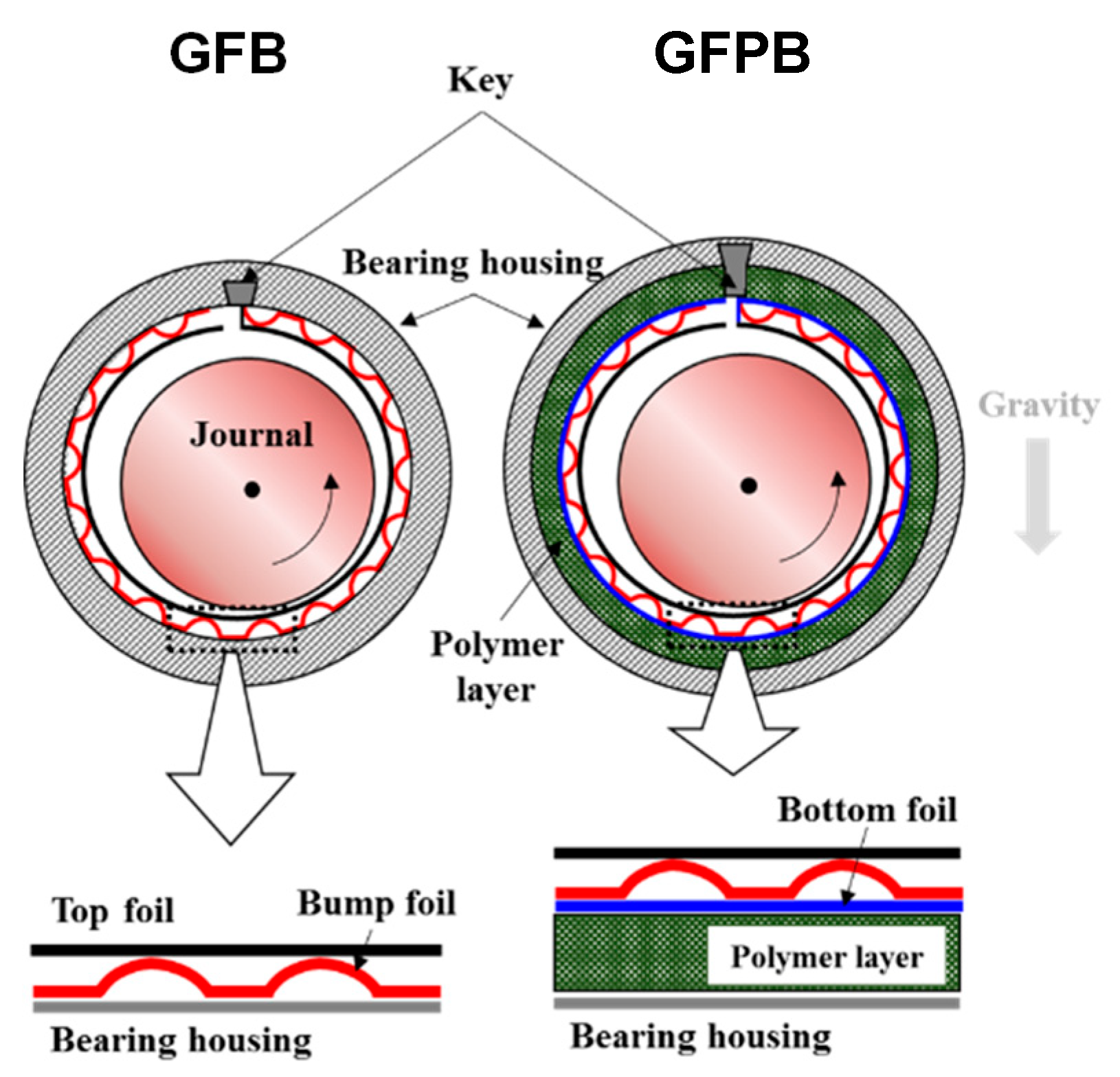
Figure 1 presents the configuration of a one-pad journal GFB and gas foil-polymer bearing (GFPB) proposed by Sim and Park [
3]. For the GFB, the top and bump foils are located between the journal and bearing housings. The top foil provides a smooth bearing surface and assists in generating a hydrodynamic film pressure between the journal and top foil. The top foil is supported on a series of bump foils, which provide structural compliance and energy dissipation, acting as springs and dampers. The GFPB consists of laminated top, bump, and bottom foils made of Inconel X-750. An additional polymer layer made of nitrile butadiene rubber is filled in the circumferential direction. The polymer layer leads to radial motions of the sub-structure, providing additional structural compliance and hysteretic damping. One end of the top, bump, and bottom foils is spot-welded to the bearing key, whereas the other end is free.
The static and dynamic performances of the GFBs mainly depend on the mechanical properties of the sub-structures, i.e., the material properties and geometrical configuration of the bump and top foils, particularly for heavily loaded GFBs at high speeds [
2]. To predict the exact rotordynamic performance of the rotor supported on GFBs, the precise estimation of the mechanical properties of the sub-structures is important [
3,
6]. Thus, studies on the mechanical properties of sub-structures have been one of the main research topics in GFBs.
Heshmat et al. [
7,
8] proposed the first simple elastic foundation model of a bump foil. The bump foils were modeled as uniform springs with structural compliance, which was determined by the material and geometric properties of the bump foil. Iordanoff [
9] presented another simple elastic foundation model of a bump foil under either free–free end or fixed–free end conditions for a single bump. Specifically, this model included the dry-friction coefficients of the sub-structures.
Subsequently, San Andres et al. [
1] proposed finite element (FE) models that coupled the elastic deformations of a two-dimensional (2D) shell or one-dimensional (1D) beam-like top foil with the bump foil deflections. The structural stiffness of the bump foil was estimated from a simple elastic foundation model [
9]. In contrast, Carpino et al. [
10] introduced a fully coupled FE model of a bump and top foil. This model included the moment, tension, curvature, and strain expressions for the cylindrical shell deflections of the foil structures. The bump foil was also considered as a continuous elastic foundation with coupled radial and circumferential deflections of the foil.
These simple elastic foundation models [
7,
8,
9] of bump foils neglect the elasticity of the top foil and consider them as an elastic foundation having a uniform stiffness coefficient. The consideration of all the effects on the properties of bearing structures is limited. This is because the stiffness coefficient is determined only by the geometry and material of the bump foil and/or dry-friction coefficients and not operation conditions. However, in practice, structural properties of the sub-structures significantly vary with the rotor speeds, deformations of the sub-structures, operation temperatures, and static and dynamic loads [
3,
11,
12].
Recently, inducing a change in the mechanical properties of the sub-structures by introducing some high damping materials in the top and bump foil structures to stabilize the rotor-bearing system is receiving increased attention. Lee et al. [
13,
14] introduced viscoelastic materials into GFBs to increase the damping characteristics of the sub-structures. These viscoelastic GFBs comprised a series of laminated structures, i.e., viscoelastic material-based top and bump foils. The experiments showed that the enhanced structural damping lowered the amplitudes of the synchronous motion near the critical speed of the rotor-bearing system.
Sim et al. [
3] experimentally evaluated the effects of high-damping sub-structures on the rotordynamic performance. The test bearings were one-pad GFBs and GFPBs with high-damping bump foil and polymer sub-structures. By conducting the 1-DOF dynamic loading tests of a flat specimen of the bearing sub-structure, they found out that the GFPBs had lower structural stiffness coefficients and higher structural loss factors than the GFBs. The rotordynamic performance measurements revealed that the GFPBs delayed the occurrence of the sub-synchronous motions and lowered the peak amplitude of the synchronous motions near the critical speed.
Zywica et al. [
15,
16,
17] performed a protective coating of the top foil with a thin fluoropolymer layer to reduce bearing friction and wear in GFBs. The rotordynamic experiment of bearings were carried out at high speeds and elevated temperatures from 20 to 290°, which are in conditions that are typical for micro-turbine operation. Furthermore, authors examined static characteristics of the bearings via static-load deflection tests. Their work suggests that the polymer layer is sufficiently applicable to GFBs in turbomachinery running in relatively high-speed and high-temperature environments. In addition, polymers have been applied to various components of rotating machinery such as a compressor impeller, a nozzle body, a ball bearing cage, and a bushing [
18,
19,
20,
21].
Similar to the earlier studies [
3,
13,
14], introducing high-damping materials in the sub-structures of the GFBs was a useful solution for improving the rotordynamic stability. However, the authors in the studies did not investigate the underlying reason for this effectiveness in improving the rotordynamic stability. Without understanding the background mechanism of GFPBs, it is difficult to expect their widespread usage even if they provide outstanding rotordynamic performance. Absence of a reliable prediction model for the structures of GFPBs also impedes the widespread usage of the bearings.
This study aims to develop a simple model for structural elasticity of GFPBs and examine stability performance of GFPBs using the model. The following work includes the structural model development of GFPBs based on Hooke’s law for the cylinder-shaped polymer layer, and the model is validated via the static-load deflection tests with a fabricated test GFPB with nitrile butadiene rubber. Static load versus displacement curve is used to validate the simple structural model. Finally, the structural model of the GFPBs is coupled with the in-house computation tool for bearing performance analysis, and performance of GPFBs is discussed in terms of polymer layer thickness and rotating speeds.
2. Simple Model for Structural Elasticity of Polymer Layer
A simple model of a cylinder-shaped polymer layer is described here to achieve a reliable estimation of the mechanical properties for GFPB structures. The mathematical approach for the cylinder-shaped polymer layer follows a thick-walled cylinder formulation based on the theory of elasticity and considers a differential element on a polymer layer. The thick-walled cylinder formulation is generally used to analyze the stress and strain relation of pressure vessels [
22,
23].
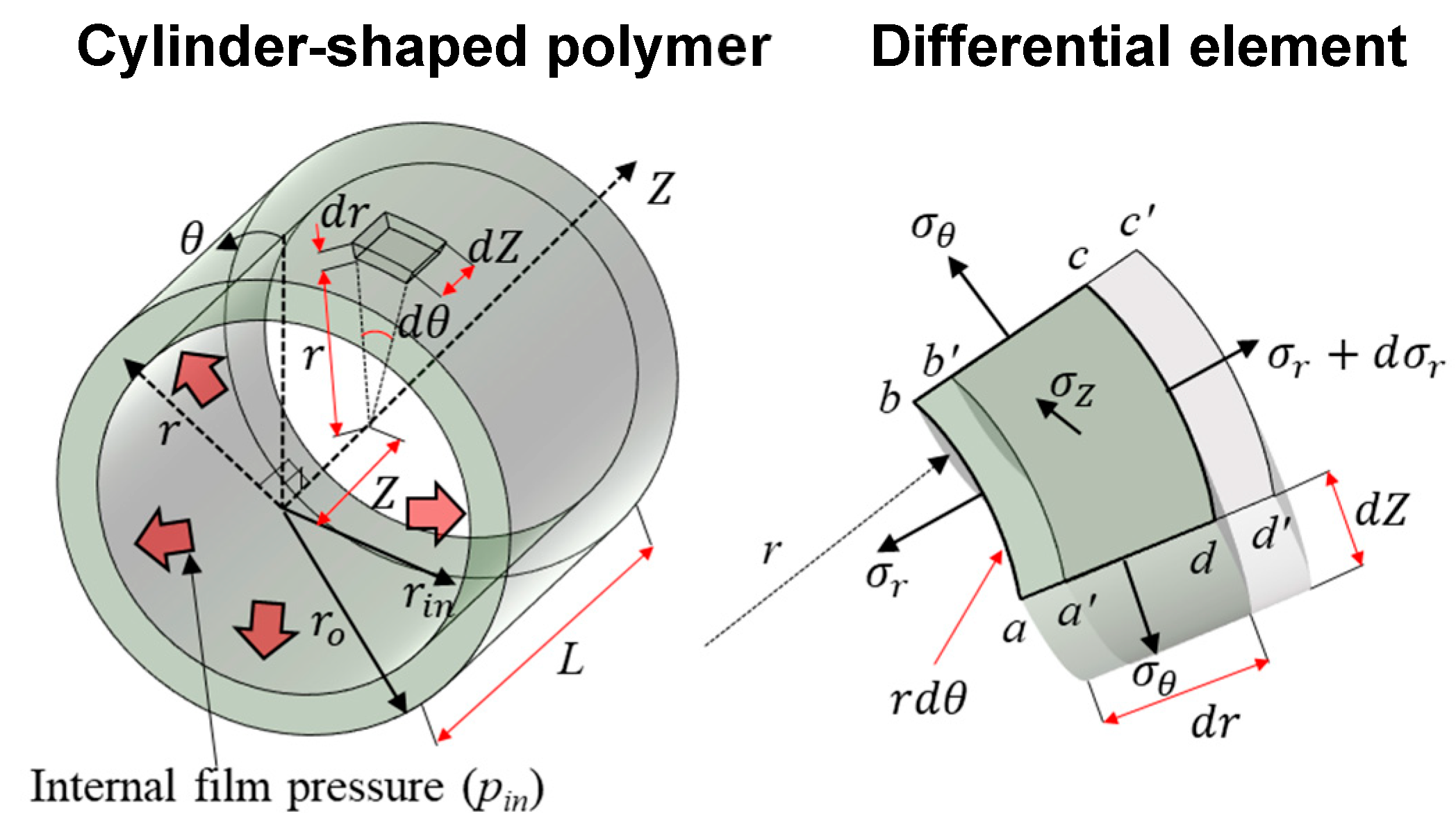
Figure 2 presents the coordinate system of a thick-wall cylinder model and normal stresses on a differential element. Cylindrical coordinate system (
r,
θ,
Z) is introduced for the cylinder, where
r,
θ, and
Z are the radial, circumferential, and axial coordinates, respectively. In this study, the polymer layer of a GFPB is modeled as a thick-wall cylinder having an inner radius (
rin), outer radius (
ro), and length (
L). The cylinder is loaded by an internal fluid-film pressure (
pin) on the inner surface of the cylinder. The outer surface is in contact with the bearing housing. Therefore, a uniform internal film pressure is assumed along the
θ and
Z coordinates.
A differential element is defined by an angular increment (
dθ), a radial increment (
dr), and an axial increment (
dZ) at the radial position (
r). The original shape is element
abcd and deformed shape by the internal film pressure is element
a′
b′
c′
d′. The radial deformation of an element (
u) is given by
aa′ and
bb′. By circular symmetry, considering the equilibrium of the differential element in the radial direction leads to an equilibrium equation, as follows:
If the axial length of the polymer layer is considerably longer than the thickness, the axial strain of the element becomes relatively small so that the element could be regarded under a plane strain condition. Moreover, the axial strain of the polymer layer is significantly constrained because of the frictional force between the polymer layer and other sub-structure, thus leading to
. From Hooke’s law, the stress and strain equations for the condition of plane strain in the cylindrical coordinates are given by [
22]
where
Ep is the Young’s modulus of the polymer material,
νp is the Poisson’s ratio of the polymer material, and the radial and circumferential strains are expressed as
εr =
du/
dr and
εθ =
u/
r, respectively.
Boundary conditions for the element are applied by considering the actual operating conditions of the polymer layer in the GFPB with the radial stress
and radial deformation
u; they are
which indicates that the inner surface of the cylinder is loaded by the internal film pressure, and the radial deformation at the outer surface of the cylinder is constrained by the bearing housing.
Substituting Equation (2) into Equation (1) and applying the boundary conditions, the general solutions can be obtained, as follows:
and the radial deformation is
which shows that the axial stress is not a function of the radial position and is determined by the geometry of the polymer layer and internal film pressure.
The equivalence between the strain energy (
Wstrain) of the polymer layer and potential energy of an equivalent virtual spring (
Wpotential) determines the equivalent stiffness per unit area of the polymer layer (
kp). The strain energy of differential elements in the radial direction and the potential energy of the equivalent virtual spring are expressed as
where
is the arbitrary deflection of the spring. Note that it is assumed that the reaction force of the equivalent spring is linearly proportional to the deflection.
3. Structural Deflection Model of GFPBs
A structural deflection model for GFPBs is established by coupling bump-foil elasticity with the structural elasticity model of polymer layers.
Figure 3 presents the coordinate systems for the deflection model with equivalent springs of GFPBs. The origin of rectangular coordinate system
X,
Y is located at the center of the bearing, and the circumferential coordinate system
θ is defined as counterclockwise from the negative
X-axis. Each single bump foil and polymer layer is modeled as circumferentially distributed equivalent springs. The springs correspond to the number of single bump foils (
Nb), which are circumferentially located at the peak of the bump arc; thus, they are located at
θi, where
i = 1 −
Nb.
Considering the force equilibrium of the applied static loads (
FX,
FY) on the journal and sum of the reaction forces of the equivalent springs (
FX,R,
FY,R) in the
X- and
Y-directions leads to
where the sum of the linear reaction force is calculated from the summation of the reaction forces of each spring (
FX,i,
FY,i) in each direction, i.e.,
FX,R =
and
FY,R =
. The reaction force of each spring is determined using its stiffness coefficient and deformation.
The spring deformation is determined from the gap between the journal and bearing surface (
τ) at the spring location
θi, as follows:
where
Cr is the bearing radial clearance, and
eX and
eY are the journal center positions in the
X- and
Y-directions, respectively. Note that when the gap becomes negative at a certain angle of the spring location, the springs at the location are engaged to generate reaction forces, whereas the springs located at the gap with positive values do not induce the reaction forces.
If the gap is negative, i.e., the shaft and bearing surface come into contact, the deformation of the spring at
θi(
δi) is expressed as
Thus, the reaction force of each spring is
where the reaction force becomes zero at
θi if
τ(
θi) > 0, and
KGFPB is the equivalent structural stiffness coefficient of the GFPB, i.e.,
KGFPB =
kGFPB unit area (=bump pitch
bearing length). The reaction force components in the
X- and
Y-directions are
and
, respectively.
The
kGFPB is estimated from a series combination of the bump and polymer springs; it is expressed as 1/
kGFPB = 1/
kb + 1/
kp. The stiffness coefficient per unit area of the equivalent bump foil springs (
kb) is determined from Iordanoff’s formula [
9] under free–free end condition, whereas the coefficient of the equivalent polymer springs (
kp) is calculated from the structural elasticity model of the polymer layer, Equation (6). Note that this simple concept that bump foil and polymer layer springs are connected serially allows us to understand complex structural mechanism of GFPBs easily. On the other hand, Schilling et al. [
24] modeled the polymer layer in the gas bearing as complex rheological elements with the discrete springs and dampers to consider viscoelastic behavior of the polymer layer.
The computational procedure is as follows. First, the gap is calculated at each angular position of the spring location using the current journal center position, and then the reaction forces of each spring are determined. Second, the force equilibrium in Equation (7) provides the updated shaft center position by using the Newton–Raphson method. The procedure is iteratively performed until the shaft center position converges within a certain level of error with .
In the prediction, a Young’s modulus of 2.5 MPa [
25] and Poisson’s ratio of 0.33 [
22] for the polymer layer are used. From Equation (6), we can estimate that the structural stiffness per unit area is 8.7 × 10
9 N/m
3 for the free–free bump and 2.9 × 10
9 N/m
3 for the polymer layer with 2 mm thickness. Consequently, the equivalent structural stiffness of the GFPB corresponds to
kGFPB = 2.18 × 10
9 N/m
3 and
KGFPB = 2.99 × 10
5 N/m with the unit area of 0.137 × 10
−3 m
2.
Note that the mechanical properties of the general polymer material vary considerably with the temperature. There are five regions of viscoelastic behavior of a polymer: glassy, glass-transition, rubbery, rubbery flow, and liquid flow regions [
22]. Because the properties change rapidly at the boundary of each region, the operating temperature of the polymer when in use should be considered when selecting the mechanical properties. In this study, it is assumed that the polymer layer in the GFPB is subjected to low temperatures, resulting from a well-cooled and low-load operation. Therefore, the temperature range of the polymer is regarded as the glassy region (25–120 °C).
4. Model Validation via Static-Load Deflection Test
The static-load deflection test in the gas bearing field generally represents a test that identifies a relationship between applied static loads and deflection of the bearing sub-structures [
26]. Ref. [
3] also carried out the static-load deflection tests with a test journal GFPB and GFB to identify assembled radial clearance of the bearings; however, the tests is performed for validating the simple structural model.
Figure 4 shows the configuration of the static-load deflection test rig setup and a test GFPB. A test GFPB has a bearing length of 30 mm and a designed radial clearance of 200 μm for a journal that has 40 mm diameter. The polymer layer, nitrile butadiene rubber (NBR), a kind of natural rubber, is used. NBR has excellent oil and abrasion resistance and is widely used for O-rings and seals. The operating temperature is −55–125 °C, and it has stable heat resistance. NBR has excellent damping characteristics compared to general engineering rubbers such as natural rubber (NR), stylene butadiene rubber (SBR), and ethylene propylene diene monomer (EPDM). Therefore, in this study, NBR polymer with a thickness of 2.0 mm (
tp = 2.0 mm),
rin = 20.92 mm, and
ro = 22.92 mm is applied to the bearing; a plate made of NBR was cut to fit the size of the bearing, then rolled up and inserted into the bearing. The design parameters for the foil structures and polymer layer are listed in
Table 1. On the other hand, the bump foil is fabricated by the press process with a flat-shaped tooling (die) with a forming load of 30 MPa. DellaCorte et al. [
27] reported that at least a load of 28 MPa is required to achieve the designed bump shapes.
As for the test rig, a stationary shaft with a diameter of 40 mm is fixed on a lathe with a three-jaw chuck and tail chuck. A test bearing is installed on the shaft, and it can be moved to one axis by a latch tool. The lathe tool achieves forward and backward motions for the test bearing, which are measured by an eddy-current displacement sensor (BENTLY NEVADA 3300 XL NSV). When the test bearing moves over its nominal radial clearance, the bearing sub-structures come into contact with the test shaft, generating a reaction force. The force is measured by a load cell (CURIOTECH CSBA-50L) located between the test bearing and latch tool. The uncertainty of the measured displacement and force is estimated to be 2 and 3%, respectively, at room temperature 21 °C. For a detailed description of the test procedure, refer to Ref. [
26].
Figure 5a shows the predicted displacement versus applied static load when the bearing radial clearance is 230, 250, and 270 μm and the measured data from the static-load deflection test. The prediction results tend to agree with the test results overall, and show high correlation especially in the range ±100 N–±200 N, although the actually designed nominal radial clearance is 200 μm. This means that actual assembled radial clearance is slightly larger than the designed value, which might be caused by a manufacturing error in height of the bump foils. It is interesting that the curve measured from the test exhibits a nonlinear behavior, particularly in the low-load regions (< ~±70 N). This phenomenon is believed to be mainly attributed to the manufacturing and assembling uncertainties of the bearing and shaft. Note that the test result indicates that there are four loading processes: pull-loading and -unloading as well as push-loading and -unloading. During these processes, the measured displacements and static loads form a hysteresis loop, whose area is related to the energy dissipation and slope correlates with the structural stiffness [
28].
Figure 5b illustrates the estimated structural stiffness as a function of the displacements from the prediction and test. All the stiffness curves are estimated by differentiating the static load versus displacement fitting functions with respect to the displacement, and the functions are listed in
Table 2. The results indicate that stiffness curves of the analysis tend to agree with the curve of the test especially in the low-displacement regions, whereas the major discrepancy occurs in the high-displacement regions.
As a result, the presented structural model of GFPBs is effective enough to predict structural behavior of GFPBs in the lightly loaded condition. In general, dynamics of rotor-bearing systems with lightly loaded condition are dominated by bearing stiffness than bearing damping effects since the stiffness determines system critical speeds and whirl frequency of instabilities. However, in some cases of high-load conditions, the model may not guarantee the accuracy of the prediction result due to the fact that the model cannot capture viscoelastic behavior of polymer layers.
5. Rotordynamic Performance Analysis of GFPBs
The rotordynamic performance analysis with respect to static and dynamic performances of the GFPBs are conducted. The structural model of the GFPBs is coupled with the in-house computation tool anchored in solving the transient Reynolds equation for an isothermal iso-viscous ideal gas and the perturbation method of GFBs, which was established from Park’s work [
29].
An unsteady compressible Reynolds equation for an isothermal and isoviscous ideal gas is expressed as
where
μ is the air viscosity, Ω is the rotor speed, and
t is the time;
p and
h are gas-film pressure and thickness, respectively. The fluid-film thickness for the GFPB is expressed in terms of the journal center positions and bearing radial clearance and deflection of the bump foil plus polymer layer (
) as
where the deflection occurs because of the compliance of the bump foil plus polymer layer, i.e.,
,
pavg is the average fluid-film pressure over the bearing length,
pa is the ambient pressure, and
is the complex structural stiffness of the GFPB expressed as
, where
γGFPB is the structural loss factor, and
j is the imaginary unit. A common approach to consider dynamic effects using static stiffness and loss factors of bearing structures is to use complex stiffness. Note that
is mechanical deflection of an equivalent spring of the bump foil plus the polymer layer caused by gas-film pressure distribution.
The structural loss factor of the GFPB can be easily estimated from a series combination relation of the bump foil and polymer layer. Thus, the structural loss factor of the GFPB is defined as
where
γp and
γb denote the loss factor of the polymer layer and bump foil, respectively. Generally, the structural loss factor of the bump foil is estimated as a constant value from 0.05 to 0.2 [
29]. In this study, a value of 0.1 is used for the foil structures. Meanwhile, the polymer layer is assumed to have a loss factor of 0.49 [
22], which is much higher than the bump foil has.
Figure 6 displays how the structural stiffness and loss factor of the GFPB, which constitute the complex structural stiffness
, vary depending on thickness of the polymer layer. It is assumed that the polymer layer has
rin = 20.92 mm, and the outer radius is varied to a value corresponding to analysis thickness. The result shows that
kGFPB becomes identical to
kp, whereas
γGFPB approaches
γb at a thick thickness. Notably, inserting a polymer layer into the GFB significantly reduces the structural stiffness of the bearing, which is accompanied by increased structural loss factor. This result implies that the engineer can properly tune bearing stiffness and damping with polymer thickness; this is a flexible and easy way for engineers. Similar consequence also can be observed in the dynamic test for structural parameter identification of GFBs and GFPBs in the early study conducted by Sim et al. [
3].
As a next step, the following performance analysis is conducted with the assumption that analysis bearings having a designed radial clearance of 200 μm are adjusted to have the clearance of 50 μm by inserting metal shims beneath the bottom foil, while not changing the inner radius of the polymer layer. That is because the bearing radial clearance is usually less than 50 μm in most practices [
30]. Note that the bearing clearance was intentionally designed as large to adjust the value as we want. The journal is subjected to a static load of 49.1 N in
X-direction, which corresponds to a journal mass of 5 kg. The important design parameter for GFPBs, that is, polymer layer thickness
tp, changes from 1 to 10 mm during the analysis.
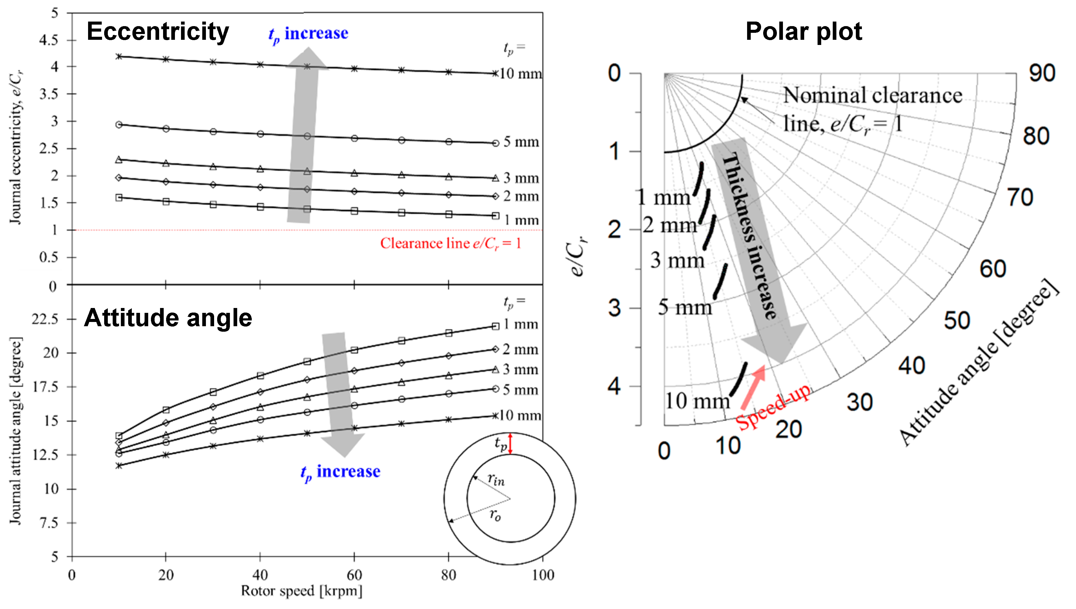
Figure 7 shows a change in journal equilibrium positions determined by the eccentricity and attitude angle depending on the polymer layer thickness as the rotor speed changes. The nondimensional form of the eccentricity is calculated from
e/
Cr where
e =
. As the polymer thickness increases, the eccentricity becomes increased significantly, i.e., the equilibrium position shifts away from the bearing center. On the other hand, the attitude angle shows a decrease trend with an increasing the thickness. These changes are mainly attributed to the small structural stiffness of GFPBs with the thick polymer layer. Another thing to discover is that as
tp increases, the slope of eccentricity and attitude angle with rotating speed decreases slightly. That is, as
tp increases, the change in the journal position to the speed becomes less sensitive, which is important information in the layout design of the rotating machinery.
The journal position information including the journal eccentricity and the attitude angle enables us to speculate the stability of GFPBs in terms of subsynchronous motions, i.e., self-excited whirls in gas bearings. It is popularly assumed that the high eccentricity and the low attitude angle indicate a potentially stable bearing [
31,
32,
33], because these conditions contribute to reduce the cross-coupled effect of the fluid film of bearings, which is one of main causes for instability in gas bearings. These desired conditions can be achieved by utilizing a thick polymer layer in GFPBs according to the results in
Figure 7. However, note that too-thick polymer layers might cause other practical problems because they produce journal’s high eccentricity of several hundred micrometers; for example, excessive radial shift of a rotor core on the rotor shaft in induction motors can bring about an electromagnetic excitation on the rotor shaft [
34]. Therefore, the selection of the polymer layer thickness in bearing design requires a comprehensive judgment including the layout of the other components and the interference with other parts.
Fluid-film pressure and thickness distributions for polymer layer thickness of 1, 5, and 10 mm at a rotor speed of 50 krpm are shown in the
Figure 8. It can be seen that the thick polymer layer reduces the peak value in the pressure and widens the pressure distribution. In addition to the pressure, the minimum film thickness region becomes widened at the thick polymer layer, which indicates that a wide wedge shape is needed to support the same static load owing to the low structural stiffness of the thick polymer layer. This can be advantageous in terms of load performance of the bearings, since wider fluid-film pressure generally can support the higher static load under a same minimum fluid-film thickness, which is also a main advantage of GFBs in comparison to rigid gas bearings [
35].
Synchronous force coefficients of the fluid film of the GFPBs are estimated via the perturbation analysis of journal harmonic motions, and direct stiffness (
kXX,
kYY) and damping (
cXX,
cYY) results are shown in
Figure 9. As the polymer layer thickness increases, direct stiffness and damping coefficients in both directions become reduced. The reductions in direct stiffness are predictable results because higher polymer thickness means lower structural stiffness. However, it is interesting that higher thickness does not generate higher direct damping coefficients of the fluid film; rather, it decreases the damping.
In GFB, the direct stiffness and direct damping coefficients are generally inversely proportional to the bearing clearance [
29]. In other words, a smaller bearing clearance reduces the average gas-film thickness and the journal forms its equilibrium position near the bearing center, so that the gas film provides high direct stiffness and direct damping to the journal motion. However, the increase in the polymer thickness of GFPB causes the journal to move away from the bearing center, as shown in
Figure 7. Therefore, the average gas-film thickness increases as shown in
Figure 8, resulting in a lower direct stiffness and direct damping coefficients of the gas film.
In addition to the reduction, asymmetry of
kXX and
kYY decreases with increasing polymer layer thickness, yielding circular journal orbits. From the point of vibration amplitude, circular orbits are preferable, since their vibration amplitude is smaller when going through a critical speed compared to the major axis of an elliptical orbit [
36].
Predicted cross-coupled stiffness (
kXY,
kYX) is shown in
Figure 10. They also get reduced significantly with increasing polymer layer thickness, and
kXY is more sensitive to the thickness than
kYX, which indicates that the differences in magnitude of
become small at high thickness. This implies a better rotordynamic stability because it means small destabilizing energy added to the rotor-bearing system [
37,
38]. Cross-coupled damping coefficients are omitted in the paper for brevity.
6. Stability Analysis of GFPBs
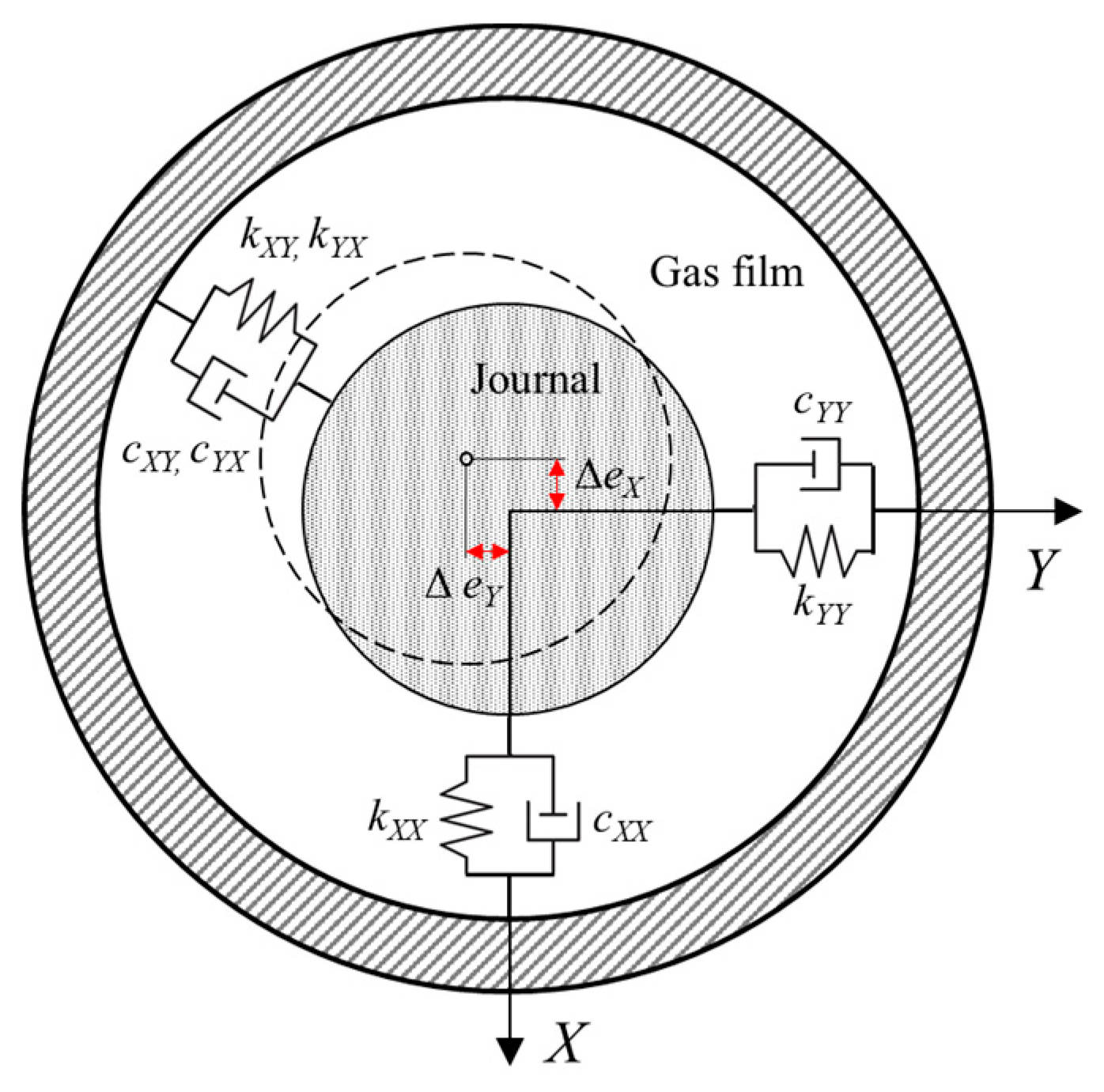
As shown in
Figure 11, the gas film can be represented by linearized springs and dampers. Where journal radial motion is quite small and about a centered position, the motion is said to be in the linear range and the gas-film forces are directly proportional to the journal displacements (Δ
eX, Δ
eY) and velocities (
,
) [
39].
The dynamic bearing reaction forces acting on the journal are as follows:
where
and
are dynamic gas-film forces.
Effective stiffness and damping are the important indicator of the stability of rotor-bearing systems. Assuming a small circular journal motion, it assumes that the direct terms become symmetric (
,
), and the cross-coupled terms are skew-symmetric (
,
). Thus, effective stiffness and damping are derived from:
where
is the rotating speed of the journal. Note that in the GFPB analysis, the journal does not move around its centered position, and the direct and cross-coupled terms are not symmetric as seen in
Figure 9 and
Figure 10. Therefore, a limited analysis of results is required about the effective stiffness and damping predictions.
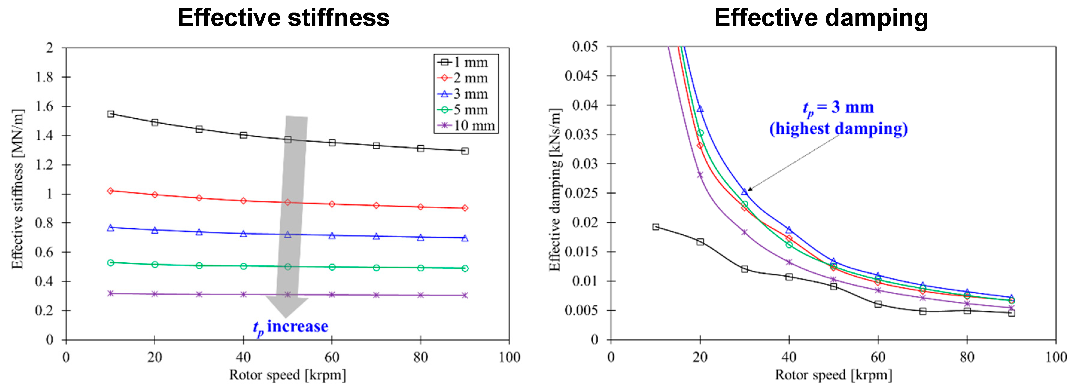
Figure 12 indicates the impact of the polymer layer thickness and rotating speed on the effective stiffness and damping. Increasing the polymer layer thickness gives the decrease in the effective stiffness and the damping trend to decrease after an increase. For the
tp = 3 mm case, the effective stiffness is reduced by 46–50%, and the effective damping increases by 47–280% compared to the
tp = 1 mm case; which shows a remarkable improvement in the effective damping. The improvement of the damping is more pronounced in low-speed areas than in high-speed ones.
As a result, the stability analysis results reveal that inserting a polymer layer with appropriate thickness (3 mm, in this study) can improve bearing damping characteristics while minimizing the decrease in stiffness characteristics. This will further reliably suppress the rigid body motions of the journal caused by critical speeds located in low-speed areas.
7. Conclusions
The scope of this paper includes development of the simple structural model for journal GFPBs and performance analysis with respect to the polymer layer thickness.
The polymer layer in a GFPB is modeled as a thick elastic cylinder having an elastic modulus and a Poisson’s ratio. Assuming a plane strain condition for the differential element of the polymer layer enables us to calculate the stress and strain relation as well as the equivalent structural stiffness; the model is called to the structural elasticity model of polymer layers. The model is combined with a structural deflection model for GFPBs with equivalent springs of bump foils and the polymer layer.
The presented models for the GFPB are validated by comparing prediction results with those estimated from the static-load deflection tests. The comparison yields reasonable displacement and stiffness relations compared to the tests, validating the proposed structural model for GFPBs in the limited condition where lightly loaded and low-speed regions that the viscoelastic effect is not dominate. The simple model allows us to easily understand the structural mechanism of GFPB. For example, it is possible to intuitively analyze how the structural characteristics of bump foil and polymer are each and what characteristics they have when they are connected in series.
Next, performance analysis is performed for the GFPB depending on the polymer layer thickness ranging from 1 to 10 mm with a journal mass of 5 kg and nominal clearance of 50 µm. The thick polymer layer significantly changes equilibrium positions of GFPBs, in particular, increasing the polymer layer thickness makes journal positions more eccentric with low attitude angle; this finding gives us the understanding that using a thick polymer layer is beneficial for weakening cross-coupled effects of the gas film. Note that it makes sure that utilizing a high thickness also accompanies large eccentricity of the journal, which may cause practical problems in applications.
Finally, stability performance of GFPBs is examined with assumption that the journal is supported by linearized springs and dampers and moves around its centered position. Analysis results reveal that there is optimized thickness of the polymer layer in terms of damping characteristics of GFPBs; in this study, the tp = 3 mm case has the highest effective damping over all rotating speeds.
Consequently, the presented structural model for GFPBs provides a reasonable performance prediction in the limited condition. The selection of the appropriate thickness considering effective stiffness and damping characteristics will determine the performance of GFPBs. We plan to design and manufacture test GFPBs with various polymer thicknesses through the simple structural model presented in this study and verify static and dynamic performance through a rotor dynamics test. Through this, we aim to provide guidelines for integrated bearing analysis, design, and application of GFPB.


