Article

Tulip-Shaped Pattern Imprinting for Omni-Phobic Surfaces Using Partially Cured Photopolymer

1
Department of Mechanical Engineering, Changwon National University, 20 Changwondaehak-ro, Uichang-gu, Changwon-si 51140, Gyeongsangnam-do, Korea
2
Department of Smart Manufacturing Engineering, Changwon National University, 20 Changwondaehak-ro, Uichang-gu, Changwon-si 51140, Gyeongsangnam-do, Korea
*
Author to whom correspondence should be addressed.
Appl. Sci. 2021, 11(4), 1747; https://doi.org/10.3390/app11041747
Submission received: 31 January 2021 / Revised: 11 February 2021 / Accepted: 14 February 2021 / Published: 16 February 2021
(This article belongs to the Special Issue Flexible and Printed Electronics)

Abstract

:
Functional films with hydrophobic, oleophobic, anti-fouling, anti-icing, anti-bacterial and low reflectance properties can be produced by patterning nano- or micro-structures on films via nano imprint lithography. Here, an omni-phobic surface showing both hydrophobicity and oleophobicity was obtained without chemical surface treatment by increasing the surface roughness and deforming the pattern morphology using only nano imprint lithography and the oxygen-inhibited curing properties of polyurethane acrylate (PUA) resin. A tulip-shaped pattern imprinting process was designed in which microscale patterns were fabricated using a porous polydimethylsiloxane (PDMS) mold with high oxygen transmission. During ultraviolet (UV) curing, a curing inhibiting layer was formed by reaction with oxygen. Next, a PDMS pad was used for the pressurized curing of the curing inhibition layer to modify the micro scale structures. Finally, final curing of the deformed pattern was performed using ultra high-power UV light. The deformation of the pattern into tulip-like shapes with increased surface roughness was confirmed by microscopy, and contact angle measurement was performed to confirm omni-phobicity. The final cured imprinted samples showed water and oil contact angles reaching 169.2° and 115°, respectively; thus, the omni-phobic surface could be demonstrated by a tulip-shaped pattern imprinting process.

1. Introduction

Functional films that realize characteristics appearing in nano- and micro-scale patterns have been fabricated biomimetically [1,2,3,4,5,6,7,8,9,10,11,12]. Two representative processes for fine patterning are photolithography and soft lithography. Although photolithography allows excellent dimensional accuracy, it is limited in the size and surface curvature of the structure that can be manufactured and the process is expensive. On the other hand, soft lithography has the advantage of being able to nano-scale a structure, a simple process with a low process cost. In this paper, micro-sized structures were patterned on a substrate using ultraviolet (UV) nano-imprint lithography among soft lithography. Among the materials used in the UV nano-imprint lithography process, polyurethane acrylate (PUA) resins include radical polymerization resins containing acrylate as the main component and cation polymerization resins containing epoxy as the main component. Radical polymerization resins have a property of inhibiting UV curing by generating an inert material (I-R-O-O) when reacting with oxygen. This characteristic deteriorates the mechanical properties of fine structures manufactured with the correct dimensions. Therefore, studies have investigated optical curing mechanisms that either block oxygen or are not affected by oxygen [13,14,15].
However, a recent study reported the use of curing inhibition characteristics to transform micro-scale line patterns. When PUA was imprinted using a porous polydimethylsiloxane (PDMS) mold, oxygen inherent in the mold cavity or penetrating the mold diffused into the resin, thus inhibiting ultraviolet (UV) curing. This produced partially cured structures with Bingham plastic behaviors; the partially cured structures deformed under the application of pressure exceeding the yield stress [16].
In this paper, a tulip-shaped pattern imprinting process was designed to fabricate an omni-phobic surface with hydrophobicity and oleophobicity by referring to the ideas of the preceding study, and hydrophobicity and oleophobicity were confirmed through static contact angle measurement [17,18]. Previously, chemical surface treatment processes such as etching [19,20,21,22,23,24,25] and deposition/coating [26,27,28,29,30,31,32,33,34] were used as a process to fabricate hydrophobic/oleophobic surfaces, but chemicals that are not good for the human body or the environment, such as fluorine, were used. In contrast, the tulip-shaped pattern imprinting process proposed in this paper has the advantages of not using chemicals harmful to humans and the environment and being able to perform the process in minutes by inducing micro-pattern deformations based on UV nano-imprint lithography. Furthermore, when applying the Roll-to-Roll process, it is possible to fabricate a large-area omni-phobic surface.

2. Process Design and Experiments

2.1. Design of The Tulip-Shaped Pattern Imprinting Process

The tulip-shaped pattern imprinting process is designed to produce an omni-phobic surface, as shown in Figure 1. The designed imprint process comprises six steps focusing on three UV curing processes. In the first to third steps of the process, PUA resin (MINS-311RM, Minuta Tech, Osan-si, Korea) is applied to a polyethylene terephthalate (PET) film in the same manner as that used for nano-imprinting. The PUA resin is then imprinted with a micro-scale pattern by sequentially applying pressure and UV curing. In the process, PDMS (RT 623, WACKER, Munich, Germany) is used as the mold material; this yields a partially cured layer from the inherent and permeated oxygen that reacts with the resin surface. The depth of the partially cured layer is affected by the UV irradiation energy; for equal process times, lower UV energies yield deeper partially cured layers. As a result, significant deformation occurs during pressurized UV curing in the fourth step of the process. This deformation increases the diameter of the upper end of the pattern, decreases the diameter and height of the lower end, and increases the surface roughness of the upper surface of the pattern. The deformed pattern has a tulip shape, and the hydrophobicity and oleophobicity of the surface are improved by the air pocket effects and increased roughness [17,19,27,35,36,37,38,39,40,41]. In the final step, the process is completed by final curing using ultra high-power UV to improve the wear resistance and omni-phobicity of the tulip structure.

2.2. Determination of PDMS Combination Ratio

The process designed to fabricate omni-phobic surfaces relied on a porous PDMS mold that permitted the PUA resin to react with oxygen during UV curing. The PDMS used in the study was manufactured by adding a curing agent for crosslinking and an oil-based silicone plasticizer (softening agent) to regulate the viscosity of the silicone rubber fluid (base). The material properties such as viscosity, hardness, elastic modulus and oxygen transmission rate varied according to the combination ratio of these materials. In order to allow pattern deformation during imprinting, a series of experiments was conducted to optimize the oxygen transmission rate of the PDMS. Five PDMS pad samples were prepared according to the combination ratios shown in Table 1.
The samples were manufactured by applying a mixed PDMS solution on a 4 inch bare silicon wafer and pressurizing it by placing a PET film on top of it. Thermal curing was performed for 4 h in an oven at 60 °C. For final curing, the thickness of the samples was measured as 100 ± 10 µm.
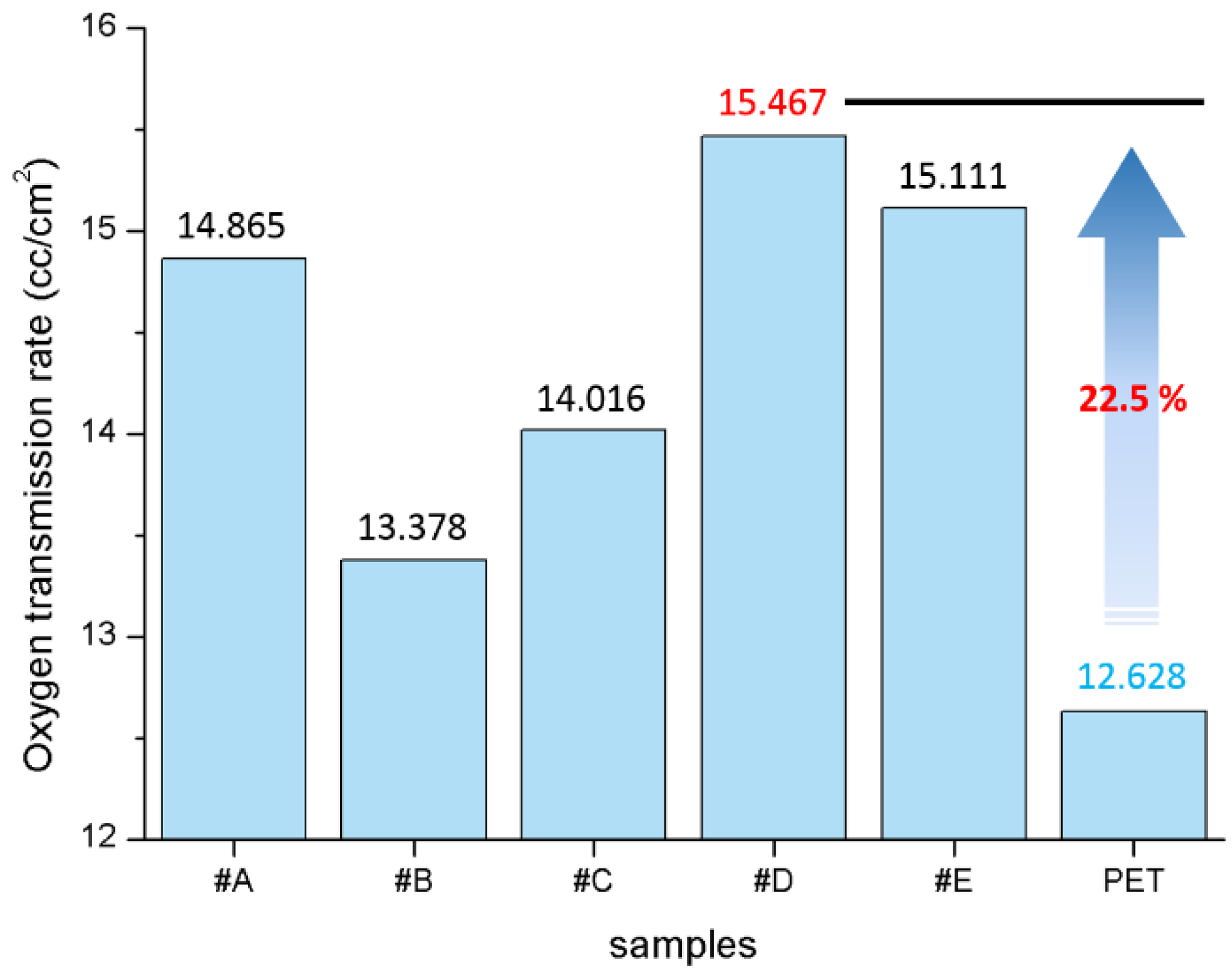
The oxygen transmission rates were measured for 2 h using the manufactured samples and an OX-TRAN instrument (Mocon Inc., Minneapolis, MN, USA). As shown in Figure 2, the measurements confirm that the concentration of oxygen is increased by 22.5% from that obtained with the PET film (12.628 cm3/cm2) to 15.467 cm3/cm2 at the combination ratio of 75:8.3:16.7 (wt %/base–curing agent–softening agent).

2.3. Comparison of Micro-Pattern Morphology Before and After Experiments

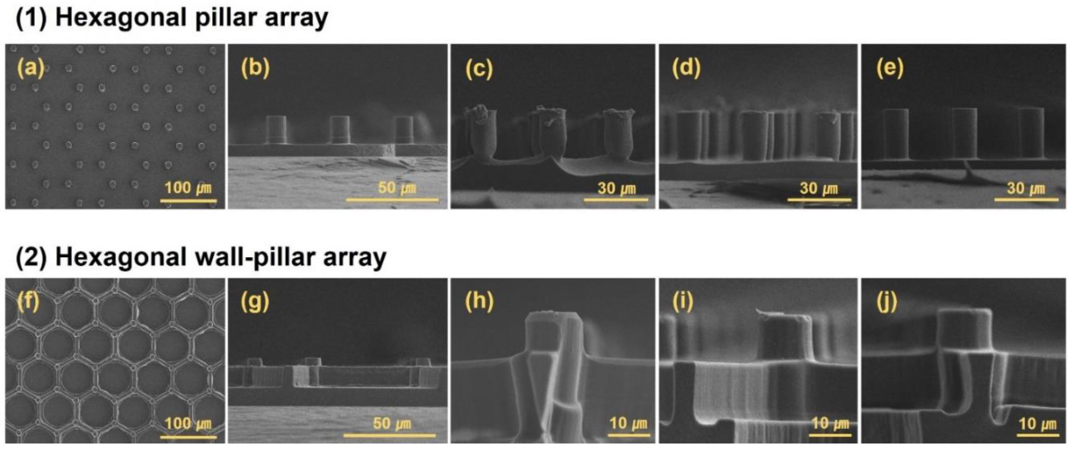
To fabricate omni-phobic surfaces, experiments were performed by designing a process wherein hydrophobicity and oleophobicity would be achieved by increasing the deformation and roughness of the surface patterning via a follow-up treatment of the curing-inhibited PUA resin. As the main variable for the experiment, the UV irradiation energy was chosen. Figure 3 shows the scanning electron microscopy (SEM) images to analyze the pattern morphology change before and after the experiments.
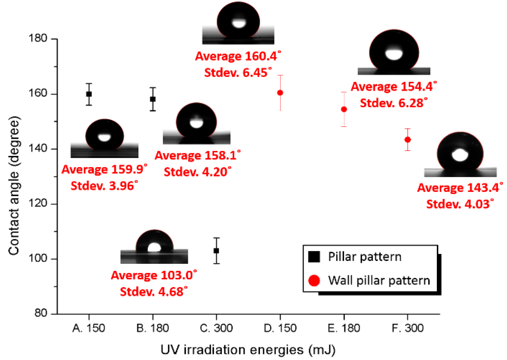
Observing the deformed pillar pattern, the diameter of the lower part of the pattern shown in Figure 3c was increased from the minimum of 6.35 μm to the maximum of 8.20 μm by irradiation with 150 mJ UV energy, as shown in the conceptual diagram. The diameter before the deformation was 10 μm; this was reduced by 1.8–3.65 μm. The diameter of the upper part was increased from 11.1 μm to 12.6 μm, indicating an increase reaching 2.6 μm. In addition, the height of the pillar was measured as 15.7 μm to 17.1 μm, reduced by 2.9–4.3 μm from the original height of 20 μm. Furthermore, irregularities of 480 nm–2.4 μm in height were generated on the upper surfaces of the pillars, thus changing the nano- and micro-scale roughness. Contact angle measurements were performed using Smart Drop equipment (FEMTOBIOMED Inc., Seongnam-si, Korea) to verify hydrophobicity, with results as shown in Figure 4. The volume of fluid in contact angle testing was set to 10 μL. The measurement was repeated at five random points on the patterned region of the film. An excellent contact angle corresponding to hydrophobicity of at least 155.9° and a maximum of 166.0° was confirmed.
For the pattern irradiated with 180 mJ UV energy (Figure 3d), there was a reduction of 0.74–1.53 μm in the diameter of the lower part, from the minimum of 8.47 μm to the maximum of 9.26 μm. The diameter of the upper part was increased by up to 1.2 μm from 10.4 μm to 11.2 μm, and the height was decreased by up to 1.3 μm from 17.2 μm to 18.7 μm. The maximum height of irregularities occurring on the upper surface of the pattern was 824 nm. The contact angle measured using the corresponding imprint sample was 150.6°–166.3°, confirming hydrophobicity.
For the pattern deformed by irradiation with 300 mJ UV energy (Figure 3e), the diameters of the top and bottom were measured as 9.79–9.92 μm and 9.66–9.79 μm, respectively, while the height increased from 18.6 μm to 20.1 μm. The measured diameter below the design dimension of 10 μm was considered an experimental error that occurred during imprinting. The difference between the top and bottom points was approximately 0.2 μm, and the degree of deformation was insignificant compared to those of the patterns shown in Figure 3c,d, so it is considered that hard curing occurred with no pattern deformation. The contact angle measurement of sample C shows the maximum of 112.5°, confirming that the deformation and roughness of the pattern affects the degree of hydrophobicity.
When reviewing the results of applying the same experimental processes to the wall-pillar structure, Figure 3h showing the structure irradiated at 150 mJ indicates that nanoscale bumps form on the top of the pillars while the width of the lower parts is significantly reduced compared to that of the upper part of the wall, forming an inverted triangle. In Figure 3i, increased roughness is observed on the upper surface, but no shape change is observed; in Figure 3j, no changes in the pattern can be seen. For the samples in Figure 3h,i,j, the measured contact angles were 153.1°–165.2°, 150.3°–161.6° and 139.7°–147.7°, respectively. In the wall-pillar pattern, as with the pillar pattern, lower irradiation energy within the curing range corresponds to greater deformation and roughness of the pattern, with contact angles of ≥160° indicating hydrophobicity.

2.4. Micro-Pattern Deformation Mechanism

The mechanism of micro-pattern deformation before and after the tulip-shaped pattern imprinting experiments with UV irradiation energy as a variable was analyzed based on the SEM images in Figure 3, as shown in Figure 5. When the imprint process is performed using a PDMS mold that can permeate or contain oxygen as it has a porous structure and a PUA resin that inhibits curing when reacted with oxygen, a partially cured layer is formed on the surface of the PUA resin that reacts with oxygen. The resulting partially cured layer is greatly affected by UV energy irradiated for curing. Additionally, an omni-phobic surface is fabricated by causing deformation of the partially cured layer and an increase in surface roughness through post-processes such as pressurization and after-curing.

2.5. Final Curing Process for Improving Durability of Micro-Pattern

For an omni-phobic surface achieved via the imprinting process, a pattern with poor durability may lose omni-phobicity under small external forces. Therefore, an additional process for improving durability after pattern imprinting is necessary. Final curing processes for durability enhancement are common when using UV curable resin. These processes promote the polymerization reaction to form polymers from the monomers and oligomers remaining in the resin after the imprinting process.
The imprint sample shown in Figure 3h was irradiated by UV energy at 630 mJ for 30 s and observed by SEM to check for pattern deformation occurring in final curing. The contact angle was also measured to check the omni-phobicity. The results are shown in Figure 6.
A comparison of the SEM images obtained before and after the final curing can be seen in Figure 3h or Figure 6a,b, respectively, showing that the edge of the wall is rugged, with bumps of 411 nm to 1.44 μm high on the tops of the pillars indicating nano- and micro-scale roughness changes. Bumps at the top and corners of the walls were increased in roughness by approximately 1 μm. Such deformation is due to excessive final curing. Monomers and oligomers are liquid at steady state (1 atm and 25 °C) and become polymerized (solidified) under intense UV energy. As the monomers and oligomers become solid polymers, they change in density, which may induce pattern deformation.
The contact angle was measured using the final cured sample, as shown in Figure 6c,d. Deionized (DI) water was used for confirming hydrophobicity and olive oil was used for confirming oleophobicity. The final curing sample showed hydrophobicity and oleophobicity of 150.2°–169.2° and 100.9°–115°, respectively.

3. Conclusions

To fabricate an omni-phobic surface by an imprint process, a tulip-shaped pattern imprinting process using a porous PDMS mold was designed, based on the curing inhibition characteristics of PUA resin that arise with reaction with oxygen. To summarize the results of the omni-phobic surface fabrication experiment with the designed process, when a pillar pattern was irradiated with 150 mJ UV energy, the diameter of the lower part of the pillars was decreased by 1.8–3.65 μm. In addition, the diameter of the upper part was increased by up to 2.6 μm, and the height of the pattern was reduced by 2.9–4.3 μm. Irregularities of 480 nm to 2.4 µm in height were generated nonuniformly on the upper flat surfaces of the pillars, thereby increasing the surface roughness. The deformed pattern showed improved air pocket effects by the increased roughness, concave bottom part and shape change of the wide top part, with hydrophobicity indicated by contact angles reaching 166°. The process was also applied to a wall-pillar pattern designed to increase the durability and air pocket effects of the pattern. The post-cured imprint sample showed hydrophobicity and oleophobicity with water and oil contact angles reaching 169.2° and 115°, respectively. We thus successfully fabricated omni-phobic surface.

Author Contributions

Conceptualization, S.H.C. and Y.T.C.; investigation, S.H.C., D.H.K. and W.Y.K.; data curation, S.H.C., S.K. (Seonjun Kim) and W.Y.K; writing—original draft preparation, S.H.C. and Y.T.C.; writing—review and editing, S.K. (Seok Kim) and Y.T.C.; visualization, S.H.C., D.H.K., S.K. (Seok Kim) and Y.T.C.; supervision, Y.T.C.; project administration, Y.T.C.; funding acquisition, Y.T.C. All authors have read and agreed to the published version of the manuscript.

Funding

This research was funded by the Ministry of Trade, Industry & Energy (MOTIE, Korea) under Industrial Technology Innovation Program No. 20000665, Development of ecofriendly and highly durable surface treatment for superomniphobic substrate on the large area over 4 m2, the Technology Innovation Program (20007064, Realization of air cleaning mobility HAMA (superhydrophobic Additive Manufactured Air cleaner)) Project funded by the Ministry of Trade, Industry and Energy (MOTIE, Korea) and the National Research Foundation of Korea (NRF) grant funded by the Korea government (MSIT) (NRF-2020R1G1A1101420).

Institutional Review Board Statement

Not applicable.

Informed Consent Statement

Not applicable.

Data Availability Statement

Not applicable.

Conflicts of Interest

The authors declare that they have no known competing financial interests or personal relationships that could have influenced the work reported in this paper.

References

  1. Gao, X.; Yan, X.; Yao, L.; Xu, L.; Zhang, K.; Zhang, J.; Yang, B.; Jiang, L. The dry-style antifogging properties of mosquito compound eyes and artificial analogues prepared by soft lithography. Adv. Mater. 2007, 19, 2213–2217. [Google Scholar] [CrossRef]
  2. Watson, G.S.; Cribb, B.W.; Watson, J.A. How micro/nanoarchitecture facilitates anti-wetting: An elegant hierarchical design on the termite wing. ACS Nano 2010, 4, 129–136. [Google Scholar] [CrossRef]
  3. Pazhanimala, S.K.; Vllasaliu, D.; Raimi-Abraham, B.T. Engineering biomimetic gelatin based nanostructures as synthetic substrates for cell culture. Appl. Sci. 2019, 9, 1583. [Google Scholar] [CrossRef] [Green Version]
  4. Bormashenko, E.; Gendelman, O.; Whyman, G. Superhydrophobicity of lotus leaves versus birds wings: Different physical mechanisms leading to similar phenomena. Langmuir 2012, 28, 14992–14997. [Google Scholar] [CrossRef]
  5. Koch, K.; Bhushan, B.; Barthlott, W. Diversity of structure, morphology and wetting of plant surfaces. Soft Matter. 2008, 4, 1943–1963. [Google Scholar] [CrossRef]
  6. Bhushan, B.; Jung, Y.C. Micro-and nanoscale characterization of hydrophobic and hydrophilic leaf surfaces. Nanotechnology 2006, 17, 2758–2773. [Google Scholar] [CrossRef]
  7. Liu, Y.; Li, X.; Jin, J.; Liu, J.; Yan, Y.; Han, Z.; Ren, L. Anti-icing property of bio-inspired micro-structure superhydrophobic surfaces and heat transfer model. Appl. Surf. Sci. 2017, 400, 498–505. [Google Scholar] [CrossRef]
  8. Lee, H.; Lee, B.P.; Messersmith, P.B. A reversible wet/dry adhesive inspired by mussels and geckos. Nature 2007, 448, 338–342. [Google Scholar] [CrossRef] [PubMed]
  9. Liu, K.; Jiang, L. Bio-inspired self-cleaning surfaces. Annu. Rev. Mater. Res. 2012, 42, 231–263. [Google Scholar] [CrossRef]
  10. Bar-Cohen, Y. Biomimetics—using nature to inspire human innovation. Bioinspir. Biomim. 2006, 1, 1–12. [Google Scholar] [CrossRef]
  11. Narazaki, A.; Oyane, A.; Miyaji, H. Laser-Induced Forward Transfer with Optical Stamp of a Protein-Immobilized Calcium Phosphate Film Prepared by Biomimetic Process to a Human Dentin. Appl. Sci. 2020, 10, 7984. [Google Scholar] [CrossRef]
  12. Bhushan, B.; Jung, Y.C. Natural and biomimetic artificial surfaces for superhydrophobicity, self-cleaning, low adhesion, and drag reduction. Prog. Mater. Sci. 2011, 56, 1–108. [Google Scholar] [CrossRef] [Green Version]
  13. Bentivoglio Ruiz, C.; Machado, L.; Volponi, J.; Segura Pino, E. Oxygen inhibition and coating thickness effects on UV radiation curing of weatherfast clearcoats studied by photo-DSC. J. Therm. Anal. Calorim. 2004, 75, 507–512. [Google Scholar] [CrossRef]
  14. Studer, K.; Decker, C.; Beck, E.; Schwalm, R. Overcoming oxygen inhibition in UV-curing of acrylate coatings by carbon dioxide inerting, Part I. Prog. Org. Coat. 2003, 48, 92–100. [Google Scholar] [CrossRef]
  15. Studer, K.; Decker, C.; Beck, E.; Schwalm, R. Overcoming oxygen inhibition in UV-curing of acrylate coatings by carbon dioxide inerting, Part II. Prog. Org. Coat. 2003, 48, 101–111. [Google Scholar] [CrossRef]
  16. Kwak, R.; Park, H.H.; Ko, H.; Seong, M.; Kwak, M.K.; Jeong, H.E. Partially cured photopolymer with gradient bingham plastic behaviors as a versatile deformable material. ACS Macro Lett. 2017, 6, 561–565. [Google Scholar] [CrossRef]
  17. Manoudis, P.N.; Karapanagiotis, I. Modification of the wettability of polymer surfaces using nanoparticles. Prog. Org. Coat. 2014, 77, 337–338. [Google Scholar] [CrossRef]
  18. Feng, L.; Zhang, Y.; Xi, J.; Zhu, Y.; Wang, N.; Xia, F.; Jiang, L. Petal effect: A superhydrophobic state with high adhesive force. Langmuir 2008, 24, 4114–4119. [Google Scholar] [CrossRef] [PubMed]
  19. Cao, L.; Hu, H.H.; Gao, D. Design and fabrication of micro-textures for inducing a superhydrophobic behavior on hydrophilic materials. Langmuir 2007, 43, 4310–4314. [Google Scholar] [CrossRef]
  20. Karlsson, M.; Forsberg, P.; Nikolajeff, F. From hydrophilic to superhydrophobic: Fabrication of micrometer-sized nail-head-shaped pillars in diamond. Langmuir 2009, 26, 889–893. [Google Scholar] [CrossRef]
  21. Wang, S.F.; Chiang, C.C. A notched long-period fiber grating magnetic field sensor based on nanoparticle magnetic fluid. Appl. Sci. 2016, 6, 9. [Google Scholar] [CrossRef]
  22. Memon, F.A.; Morichetti, F.; Melloni, A. Waveguiding light into silicon oxycarbide. Appl. Sci. 2017, 7, 561. [Google Scholar] [CrossRef] [Green Version]
  23. Wang, C.J.; Ke, Y.; Shiu, G.Y.; Chen, Y.Y.; Lin, Y.S.; Chen, H.; Lin, C.F. InGaN Resonant-Cavity Light-Emitting Diodes with Porous and Dielectric Reflectors. Appl. Sci. 2021, 11, 8. [Google Scholar] [CrossRef]
  24. Durret, J.; Szkutnik, P.D.; Frolet, N.; Labau, S.; Gourgon, C. Superhydrophobic polymeric films with hierarchical structures produced by nanoimprint (NIL) and plasma roughening. Appl. Surf. Sci. 2018, 445, 97–106. [Google Scholar] [CrossRef]
  25. Pan, L.; Dong, H.; Bi, P. Facile preparation of superhydrophobic copper surface by HNO3 etching technique with the assistance of CTAB and ultrasonication. Appl. Surf. Sci. 2010, 257, 1707–1711. [Google Scholar] [CrossRef]
  26. Ozaki, R.; Ishida, K.; Morita, E.; Hanada, Y. Nanoparticle Deposition of Fluoropolymer CYTOP via Holographic Femtosecond Laser Processing and Its Biochip Application. Appl. Sci. 2020, 10, 7243. [Google Scholar] [CrossRef]
  27. Cao, L.; Price, T.P.; Weiss, M.; Gao, D. Super water-and oil-repellent surfaces on intrinsically hydrophilic and oleophilic porous silicon films. Langmuir 2008, 24, 1640–1643. [Google Scholar] [CrossRef]
  28. Bellanger, H.; Darmanin, T.; De Givenchy, E.T.; Guittard, F. Influence of intrinsic oleophobicity and surface structuration on the superoleophobic properties of PEDOP films bearing two fluorinated tails. J. Mater. Chem. A 2013, 1, 2896–2903. [Google Scholar] [CrossRef]
  29. De Leon, A.C.C.; Pernites, R.B.; Advincula, R.C. Superhydrophobic colloidally textured polythiophene film as superior anticorrosion coating. ACS Appl. Mater. Inter. 2012, 4, 3169–3176. [Google Scholar] [CrossRef]
  30. Bhushan, B.; Jung, Y.C. Wetting, adhesion and friction of superhydrophobic and hydrophilic leaves and fabricated micro/nanopatterned surfaces. J. Phys. Condens. Mat. 2007, 20, 225010. [Google Scholar] [CrossRef] [Green Version]
  31. Li, M.; Xu, J.; Lu, Q. Creating superhydrophobic surfaces with flowery structures on nickel substrates through a wet-chemical-process. J. Mater. Chem. 2007, 17, 4772–4776. [Google Scholar] [CrossRef]
  32. Huang, J.; Ge, S.; Wang, H.; Chen, R. Study on Preparation and Properties of Intrinsic Super-Hydrophobic Foamed Magnesium Oxychloride Cement Material. Appl. Sci. 2020, 10, 8134. [Google Scholar] [CrossRef]
  33. Song, J.S.; Park, Y.S.; Kim, N.H. Hydrophobic Anti-Reflective Coating of Plasma-Enhanced Chemical Vapor Deposited Diamond-Like Carbon Thin Films with Various Thicknesses for Dye-Sensitized Solar Cells. Appl. Sci. 2021, 11, 358. [Google Scholar] [CrossRef]
  34. Chen, Z.; Liu, X.; Wang, Y.; Li, J.; Guan, Z. Highly transparent, stable, and superhydrophobic coatings based on gradient structure design and fast regeneration from physical damage. Appl. Surf. Sci. 2015, 359, 826–833. [Google Scholar] [CrossRef]
  35. Wenzel, R.N. Surface roughness and contact angle. J. Phys. Chem. 1949, 43, 1466–1467. [Google Scholar] [CrossRef]
  36. Wenzel, R.N. Resistance of solid surfaces to wetting by water. Ind. Eng. Chem. 1936, 28, 988–994. [Google Scholar] [CrossRef]
  37. Cassie, A.B.D.; Baxter, S. Wettability of porous surfaces. T. Faraday Soc. 1944, 40, 546–551. [Google Scholar] [CrossRef]
  38. Celia, E.; Darmanin, T.; De Givenchy, E.T.; Amigoni, S.; Guittard, F. Recent advances in designing superhydrophobic surfaces. J. Colloid Interf. Sci. 2013, 402, 1–18. [Google Scholar] [CrossRef]
  39. Wang, S.; Liu, K.; Yao, X.; Jiang, L. Bioinspired surfaces with superwettability: New insight on theory, design, and applications. Chem. Rev. 2015, 115, 8230–8293. [Google Scholar] [CrossRef] [PubMed]
  40. Zhu, P.; Kong, T.; Tang, X.; Wang, L. Well-defined porous membranes for robust omniphobic surfaces via microfluidic emulsion templating. Nat. Commun. 2017, 8, 15823. [Google Scholar] [CrossRef] [Green Version]
  41. Seo, D.; Cha, S.K.; Kim, G.; Shin, H.; Hong, S.; Cho, Y.H.; Chun, H.; Choi, Y. Flexible and stable omniphobic surfaces based on biomimetic repulsive air-spring structures. ACS Appl. Mater. Inter. 2019, 11, 5877–5884. [Google Scholar] [CrossRef] [PubMed]
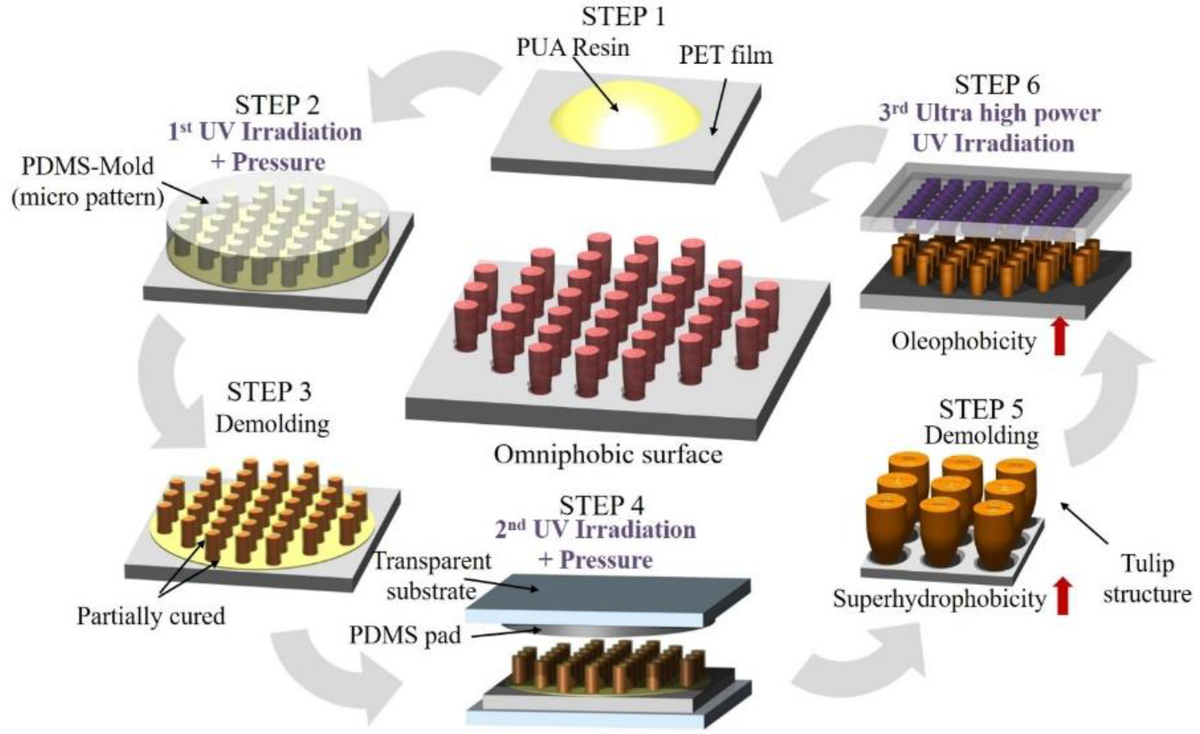
Figure 1. Flow diagram of designed tulip-shaped pattern imprinting process.
Applsci 11 01747 g001
Figure 2. Oxygen transmission rate according to combination ratio of polydimethylsiloxane (PDMS).
Applsci 11 01747 g002
Figure 3. Micro-pattern deformation before and after tulip-shaped pattern imprinting process (variable: ultraviolet (UV) energy). (a,b) Hexagonal pillar array pattern morphology before experiments. (ce) Hexagonal pillar array pattern morphology after experiments; UV irradiation energy: (c) 150 mJ, (d) 180 mJ, (e) 300 mJ. (f,g) Hexagonal wall-pillar array pattern morphology before experiments. (hj) Hexagonal wall-pillar array pattern morphology after experiments; UV irradiation energy: (h) 150 mJ, (i) 180 mJ, (j) 300 mJ.
Applsci 11 01747 g003
Figure 4. Contact angle measurement results of imprint film according to UV irradiation energies.
Applsci 11 01747 g004
Figure 5. Mechanism of micro-pattern deformation after tulip-shaped pattern imprinting process.
Applsci 11 01747 g005
Figure 6. Micro-pattern deformation and improvement of omni-phobicity after final curing pro-cess; contact angle: (a) 50 μm, (b) 10 μm, (c) 160.3° ± 9.56°, (d) 105.9° ± 7.92°.
Applsci 11 01747 g006
Table 1. Combination ratios of PDMS samples.
SampleBase (wt %)Curing Agent (wt %)Softening Agent (wt %)
#A76.110.913
#B78.38.713
#C79.77.313
#D758.316.7
#E72820
Publisher’s Note: MDPI stays neutral with regard to jurisdictional claims in published maps and institutional affiliations.