Article

Evaluating the Early-Age Crack Induction in Advanced Reinforced Concrete Pavement Using Partial Surface Saw-Cuts

Department of Civil Engineering, Ghent University, Technologiepark 60, B-9052 Zwijnaarde, Belgium
*
Author to whom correspondence should be addressed.
Appl. Sci. 2021, 11(4), 1659; https://doi.org/10.3390/app11041659
Submission received: 14 January 2021 / Revised: 6 February 2021 / Accepted: 10 February 2021 / Published: 12 February 2021

Abstract

:
The technological innovation of continuously reinforced concrete pavement (CRCP) that contains a significantly reduced amount of reinforcement and the same fundamental behavior as CRCP is called advanced reinforced concrete pavement (ARCP). This new concept of a rigid pavement structure is developed to eliminate unnecessary continuous longitudinal steel bars of CRCP by using partial length steel bars at predetermined crack locations. In Belgium, partial surface saw-cuts are used as the most effective crack induction method to eliminate the randomness in early-age crack patterns by inducing cracks at the predetermined locations of CRCP. The reinforcement layout of ARCP is designed based on the distribution of steel stress in continuous longitudinal steel bar in CRCP and the effectiveness of partial surface saw-cuts as a crack induction method. The 3D finite element (FE) model is developed to evaluate the behavior of ARCP with partial surface saw-cuts. The early-age crack characteristics in terms of crack initiation and crack propagation obtained from the FE simulation are validated with the field observations of cracking characteristics of the CRCP sections in Belgium. The finding indicates that there is fundamentally no difference in the steel stress distribution in the partial length steel bar of ARCP and continuous steel bar of CRCP. Moreover, ARCP exhibits the same cracking characteristics as CRCP even with a significantly reduced amount of continuous reinforcement.

1. Introduction

Early-age cracking inevitably occurs in concrete pavements because of the temperature differences and stress development during the hardening process of concrete [1]. For this reason, transverse joints in jointed plain concrete pavement (JPCP) are intended to relieve the stresses in the concrete slab caused by environmental loading. Severe distress in JPCP includes the spalling and faulting over these joints, which increase the maintenance and rehabilitation cost and associated user inconvenience due to traffic control. The continuous joints repairing throughout the life span of JPCP originates the concept of continuously reinforced concrete pavement (CRCP) [2,3,4,5,6,7]. The original intention of CRCP is to eliminate the transverse joints and enhance the pavement service life with minimal maintenance [8,9,10,11,12,13,14].
CRCP contains steel bars continuously in the longitudinal direction and no gaps for transverse joints. Hence, the cracking is allowed to occur as a result of the volumetric changes in the concrete pavement slab under environmental loads. The continuously placed longitudinal steel bars are intended to hold the cracks so tight that the pavement concrete slab behaves like a continuous system. As CRCP is constructed without any intended joints, no repairing and maintenance of joints are required. Consequently, the overall life cycle cost of CRCP is less than that of JPCP. The proponents of CRCP cite durability, sustainability, and low maintenance cost, which made it as durable pavement requiring little maintenance. For the past few decades, most of the countries in Europe including Belgium have been using CRCP to build high priority and heavily loaded roadways [9,15,16,17,18,19,20,21,22,23,24]. The performance of CRCP is mainly dependent on the development of early-age crack pattern caused by environmental loading [10,11,12,25,26,27,28,29,30,31,32]. Different crack induction methods have been adopted to induce cracks from the designated locations, aiming to reduce the probability of cluster crack formation in the transverse crack pattern, which eventually leads to the development of severe distress such as punch-out in CRCP. In Belgium, the active crack control method in the form of transverse partial surface saw-cuts at one of the outer edges of the concrete slab has been proven as the most effective crack induction method for inducing the cracks from pre-determined locations (saw-cut tips) of CRCP [13,15,26,27].
As CRCP is designed to crack naturally, randomly occurring cracks such as divided cracks, Y cracks, diagonal cracks, and narrowly spaced cluster cracks inevitably take place during early age, and are held tightly by the continuous longitudinal steel bars. Therefore, the main role of continuous longitudinal reinforcement in CRCP is to prevent excessive crack openings for fulfilling the serviceability requirements within the desired limits [8,29,33,34,35,36,37,38,39,40]. Hence, the initial construction cost of CRCP is always much higher than that of other types of concrete pavements because of the larger amount of longitudinal steel throughout the length of the concrete slab. The effective crack inductions over the designated locations in the concrete slab could reduce the substantial amount of continuous longitudinal steel without compromising the pavement performance and intended service life of CRCP; consequently, the initial construction cost of CRCP could become comparable to those of other concrete pavements.
A state-of-the-art concrete pavement structure called advanced reinforced concrete pavement (ARCP) is a concrete slab reinforced with a combination of continuous and partial longitudinal steel bars throughout the length of the pavement [37]. Continuous longitudinal steel bars are replaced with partial steel bars at the crack locations to decrease the total amount of reinforcement and corresponding initial construction cost. In other words, the unnecessary continuous longitudinal steel bars are removed in the concrete slab, where there is the least probability of cracking. The concept and reinforcement design layout of ARCP are comprehensively explained with respect to CRCP. The selection of the most appropriate crack induction method for ARCP is a main focus.
The performance of ARCP is mainly dependent on the actively induced crack characteristics. This novel rigid pavement structure has not been yet implemented in building of roadways. Moreover, the cracking behavior of ARCP using partial surface saw-cuts has not been evaluated. Although, the previously used automated tape insertion crack induction strategy for CRCP has been applied to ARCP for actively inducing cracks at predetermined locations [37]. However, some demerits such as construction disruption at every insertion and concrete spalling are associated with this type of crack induction strategy, as reported in the performance evaluation of CRCP [10,11,12].
Therefore, the main objective of the present study is to evaluate the early-age crack induction in ARCP subjected to external varying temperature field by employing the active crack control method through partial surface saw-cuts and to compare with the cracking behavior of CRCP. The feasibility study of this crack induction method is carried out based on the field observation of cracking developments on the CRCP sections in Belgium. For this purpose, the three dimensional (3D) finite element (FE) model was developed using the FE tool DIANA 10.3 to simulate early-age crack induction in CRCP and ARCP segments. The field observations of cracking characteristics of the active crack control and passive crack control CRCP sections are used to validate the results obtained from the FE simulation. A comparison is made between CRCP and ARCP with respect to the early-age crack characteristics, development of maximum steel stress, and amount of longitudinal reinforcement used.

2. Concept of ARCP

When the tensile stress exceeds the tensile strength of concrete, a crack occurs to relieve the stress. CRCP is known for its randomly occurring cracks at an early age. The volume changes in the concrete slab due to environmental loading are restrained by a huge amount of continuous longitudinal reinforcement, leading to the development of internal stresses in both concrete slab and longitudinal steel bars [38,41,42,43]. The reinforcement in CRCP is required only at the crack locations. Figure 1 shows the tensile stresses in the steel bar and concrete at the cracks in CRCP at early age. The stress values are larger during the initial cracking and an ample amount of reinforcing steel is required to avoid the failure of steel. As more cracks appear with the passage of time—in other words, when the crack spacing decreases—the stresses in concrete and continuous steel bar decrease, as shown in Figure 1b,c. This implies that, when cracking initiates in CRCP with large crack spacing, an ample amount of steel is required, but, when the CRCP fully cracks with small crack spacing, the required steel is much lower than the initial amount of steel.
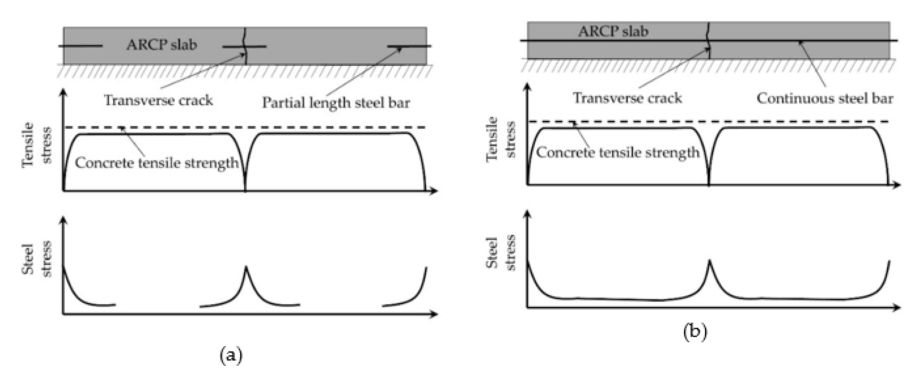
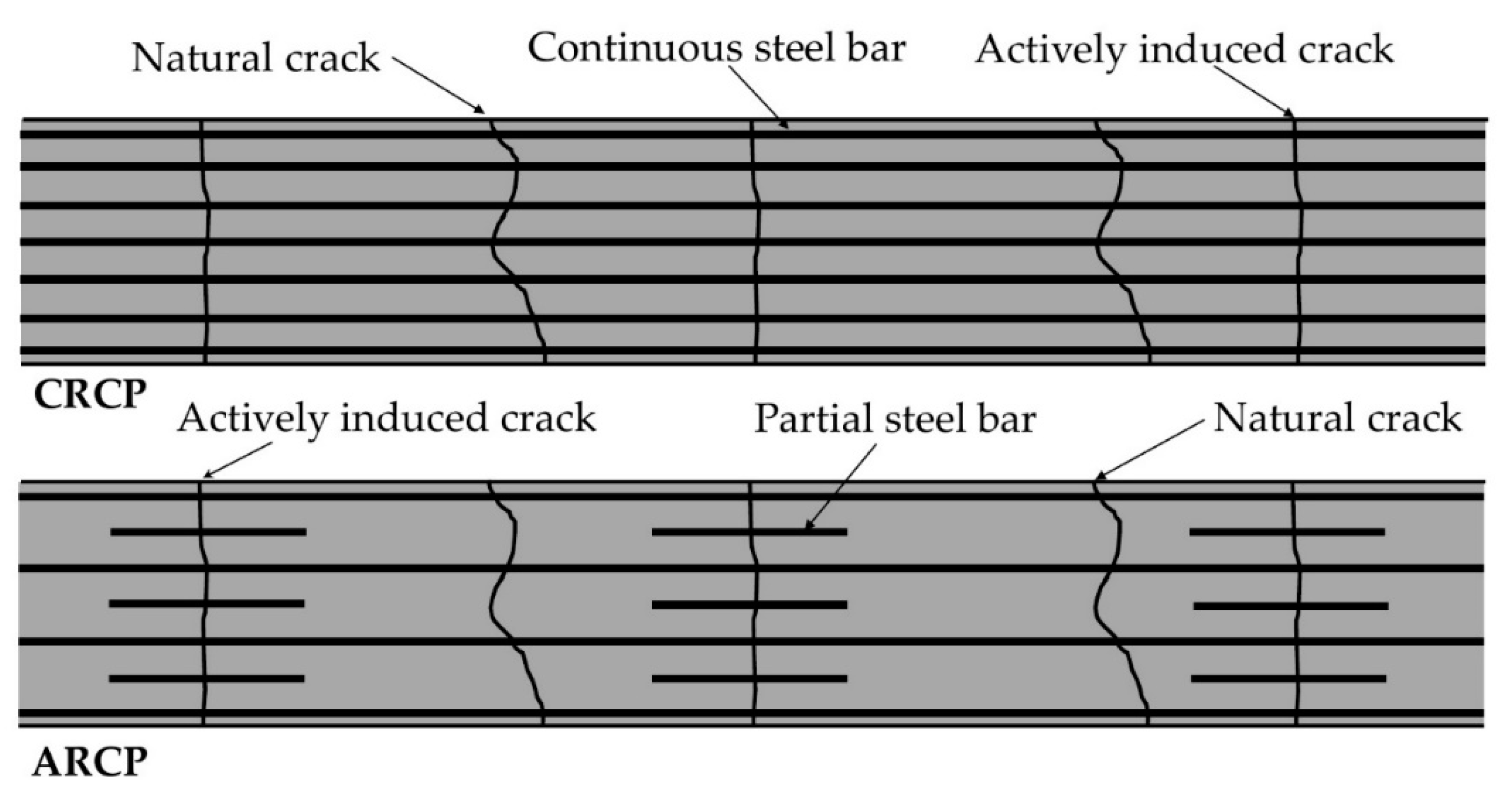
When cracks are induced at the designated locations, the same number of continuous steel bars in CRCP at the crack interfaces could be replaced with the partial length steel bars, as shown in Figure 2a. The stresses in partial steel bars are basically the same as those in continuous steel bars, as shown in Figure 2b. The continuous steel bars in between the intentionally induced cracks are intended to hold freely formed cracks between the induced cracks, as shown in Figure 3. This type of pavement structure is called the advanced reinforced concrete pavement (ARCP). Hence, a considerable amount of reinforcement can be reduced by eliminating the unnecessary continuous steel bars in CRCP without compromising the fundamental behavior of CRCP. One of the major drawbacks of CRCP, the high initial construction cost, could be eliminated with the choice of ARCP.

3. Cracking Behavior of CRCP Sections in Belgium

Since 1970, Belgium has been using the CRCP concept to construct motorways. To achieve a desirable crack spacing pattern, the standard design concept for CRCP in Belgium has been modified over the years, as demonstrated in Table 1 [12,13,20,21,22,23,44]. However, the cluster crack formations and associated distresses could not be effectively eliminated. The field observations of cracking development on the CRCP sections without an active crack control method on the E17 Motorway in Belgium exhibited the randomly occurring transverse crack pattern with a higher percentage of closely spaced cracks, as shown in Figure 3. It was also observed that this passive nature of crack induction was one of the main contributing factors towards the development of punch-out and spalling in CRCP sections [12,13,20,44].
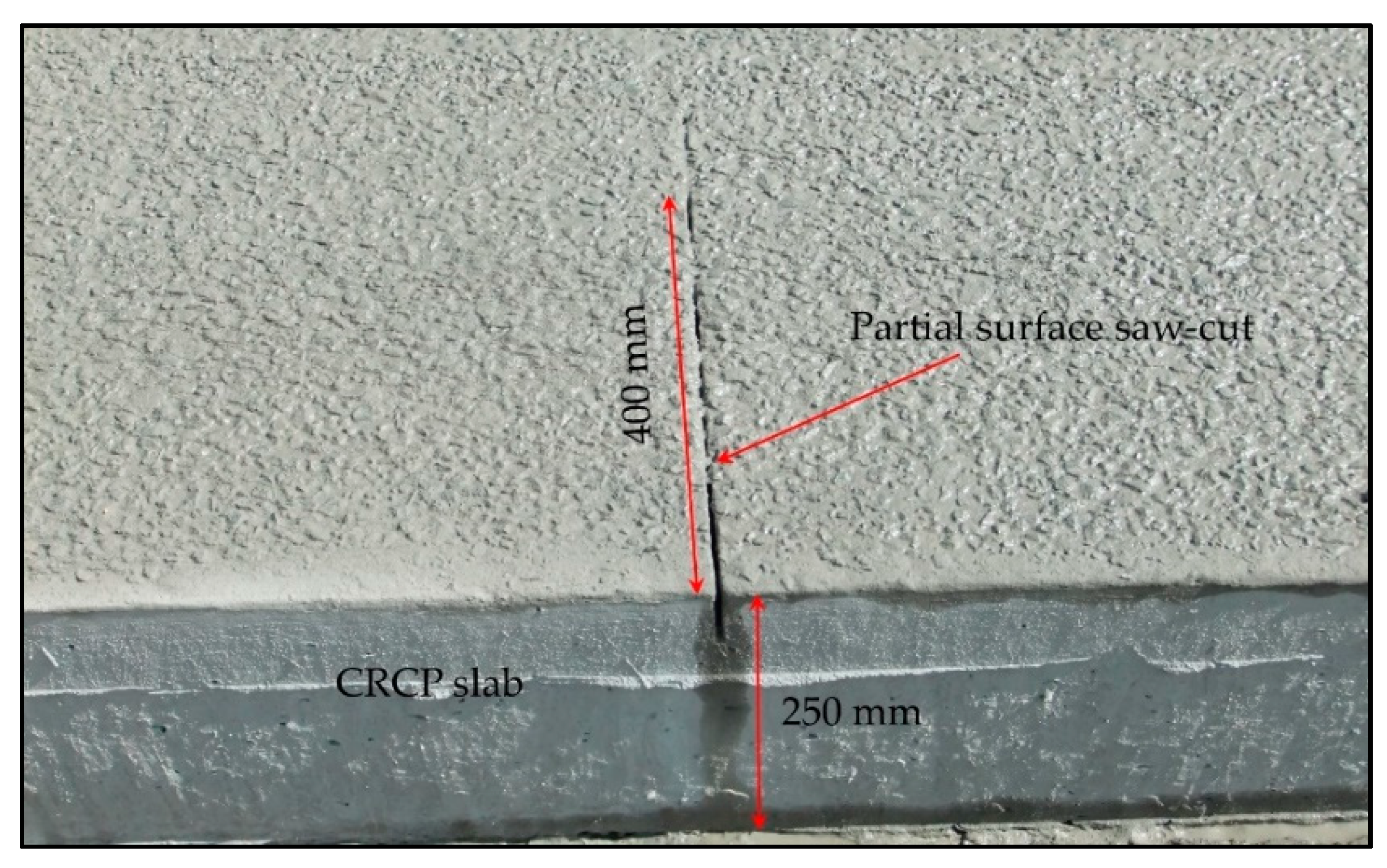
To eliminate the potential risk of the punch-out development associated with the clusters of closely spaced cracks in CRCP, the transverse partial surface saw-cuts as a crack induction method was proposed for Belgian conditions [13]. This method was applied to the CRCP sections in the reconstruction project of Motorway E313 in Belgium. In this project, two saw-cut depths of 30 mm and 60 mm were used to evaluate the effect of notch-depth on the cracking characteristics of active crack control CRCP sections. Partial surface saw-cuts were made at the edge of the outer pavement lane within 24 h after the concrete placement [12,13], as shown in Figure 4. More details related to the construction of both motorways are represented in the literature [12].
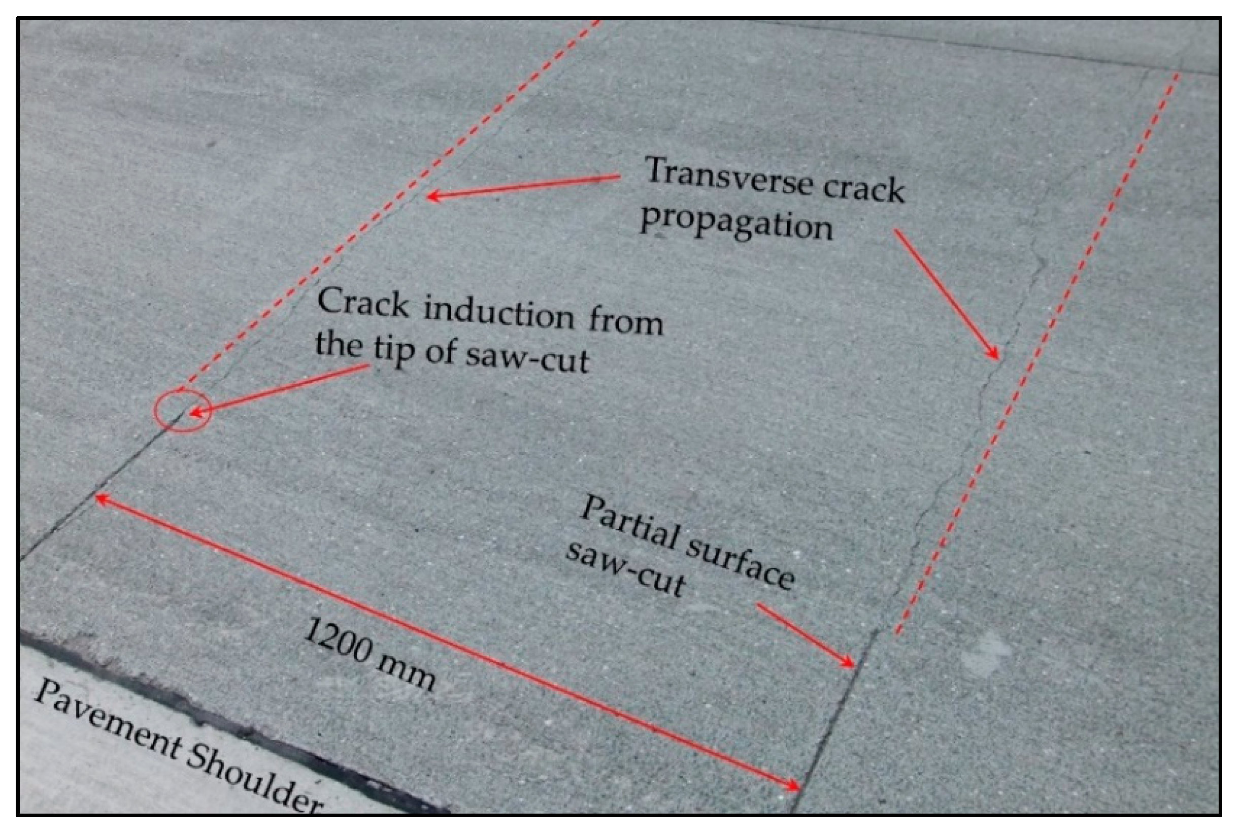
Regular surveys of crack developments on the active crack control CRCP sections were conducted right after the construction without considering the traffic load. It was observed that cracks initiated exactly from the tips of partial surface saw-cuts and propagated along the width of the concrete slab, as illustrated in Figure 5. A desirable crack pattern with uniform crack spacing was observed [12,13]. To evaluate the effectiveness of partial surface saw-cuts to induce cracks over the designated locations of the concrete slab, the observed crack patterns of these test sections were compared with those of CRCP sections on Motorway E17 in Belgium. Field investigation indicated that the CRCP sections on Motorway E17 (passive crack control sections) experienced the punch-out development more than those on Motorway E313 (active crack control sections) [12,20,44]. The majority of punch-out formations and concrete spalling over the surface of the pavement slab were triggered by the cluster of closely spaced crack patterns, as illustrated in Figure 3.
The survey results of crack developments on the CRCP sections of Motorway E313 are demonstrated in Table 2. For the CRCP sections with deeper saw-cut (60 mm), all the observed cracks were induced from notches during the initial days after construction, as shown in Figure 5. As can clearly be observed in Table 2, about 78.6% of cracks were initiated from notches after a period of two months. Meanwhile, the shallower saw-cut CRCP sections exhibited this value equal to 56.5% [12,13]. This illustrates that the deeper saw-cut could be more effective than the shallower saw-cut in inducing early-age cracks from pre-defined locations (saw-cut tips) of the CRCP sections. Even in the later-age of CRCP, these partial surface saw-cuts remained quite active for initiating new more cracks, as demonstrated in Table 2.
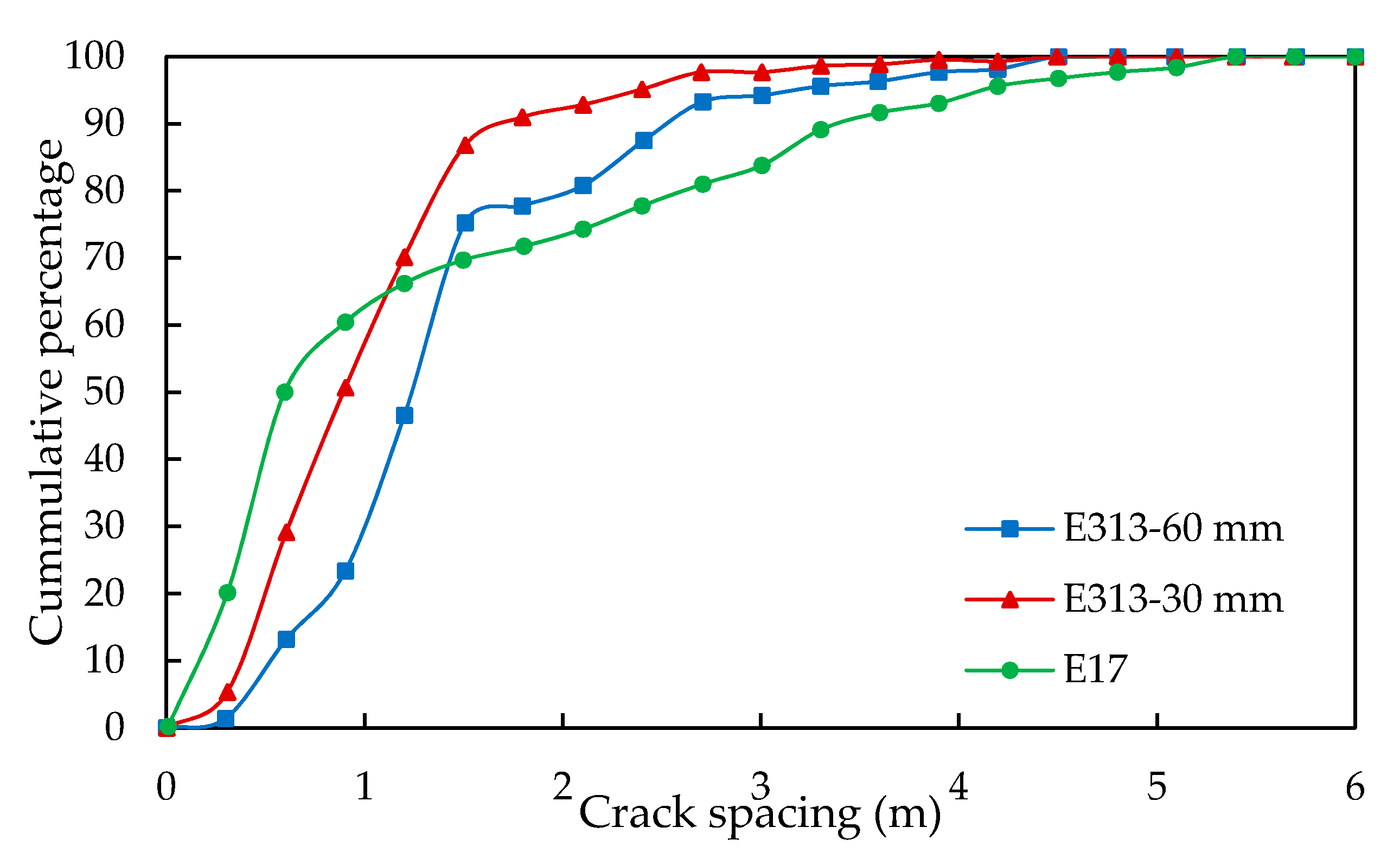
The cracking characteristics of the crack pattern in terms of cumulative crack spacing distributions on the CRCP sections of both Motorway E313 and E17 are illustrated in Figure 6. Owing to the passive nature of crack development, the CRCP sections on Motorway E17 exhibited only 27% of total cracks within a desirable range of crack spacing (0.6–2.4 m) and more than 50% of total cracks were spaced less than 0.6 m (closely-spaced cracks), as shown in Figure 6. Therefore, the crack pattern observed on the E17 sections was categorized as low mean crack spacing, which posed a potential risk of punch-out formation, as demonstrated in Figure 3. On the other hand, a favorable crack spacing distribution (0.6–2.4 m) of the crack pattern was observed on the active crack control CRCP sections. For deeper saw-cut sections, only 13% of total cracks were spaced less than 0.6 m, and more than 74% of cracks were within a favorable cracking spacing range of 0.6 m to 2.4 m. Meanwhile, in the case of shallower saw-cut sections, 66% of total cracks were within this range [12,13,20,44]. Based on these field findings, the partial surface deeper saw-cuts could be employed as the most effective crack induction method to induce cracks at pre-defined locations of the CRCP section, as shown in Figure 5.
Hence, the crack control method in the form of the partial surface saw-cut (60 mm) is assumed as the most appropriate and effective crack induction method for the reinforcement design layout of ARCP in the present study. The variation of steel stresses along the length of continuous longitudinal steel bars at the crack interface is used to decide the length of partial steel bars for the reinforcement design of ARCP [37]. Based on this concept, the overall amount of longitudinal reinforcement is reduced by replacing the continuous steel bars with partial length ones.

4. Finite Element Modeling

The FE program simulates the heat of hydration and corresponding temperature development based on the degree of reaction. The 3D FE model of active crack control CRCP segment with deeper saw-cuts, as used on the E313 section, was developed to predict the early-age crack induction under external varying temperature field conditions. The staggered structural-flow analysis, which is a special feature available in FE program DIANA 10.3, is performed to study the cracking induction associated with the temperature development calculated by transient heat flow analysis and stress computation by structural analysis. The evolution of concrete mechanical properties (compressive strength, tensile strength, and modulus of elasticity) is incorporated into the FE model in accordance with the Euro-code 2 EN 1992-1-1 concrete material model available in the DIANA tool [45].

4.1. Model Geometry

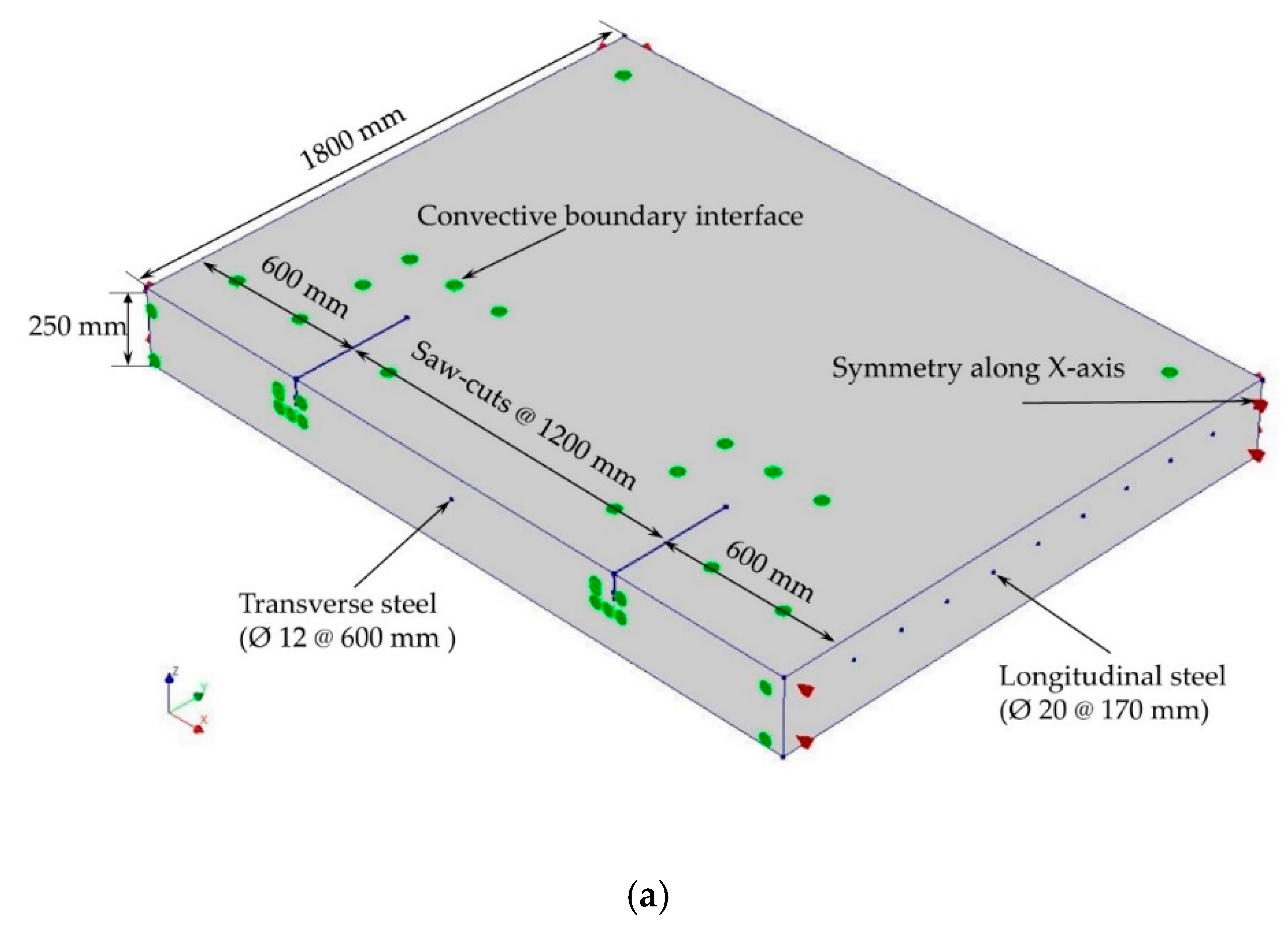
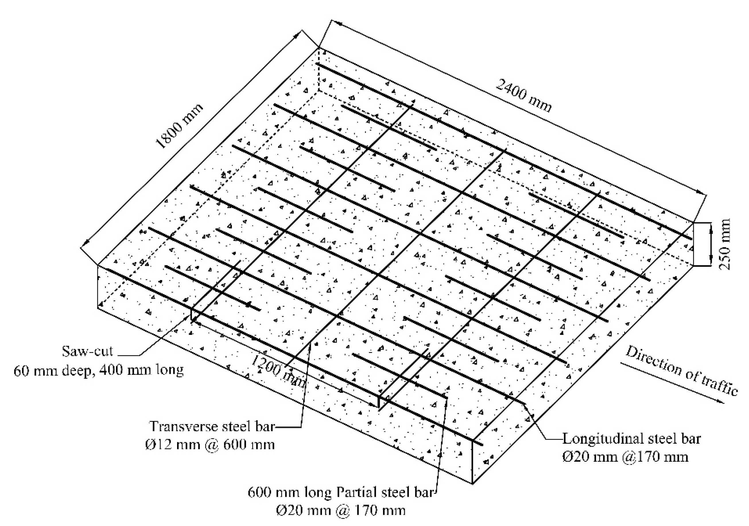
Following the current standard CRCP practice in Belgium, partial surface saw-cuts at a spacing of 1200 mm are made at one of the outer edges of the concrete slab. An intermediate 50 mm thick asphalt layer is provided between the 250 mm thick concrete slab and the 200 mm thick lean concrete to avoid direct contact of the slab with the base. The saw-cut with a depth of 60 mm, length of 400 mm, and width of 4 mm, as employed on the Motorway E313 CRCP sections, is taken into account in the development of the reference 3D FE model for simulating the early-age crack induction in CRCP. The continuous longitudinal steel bars of 20 mm diameter are placed at a spacing of 170 mm along the length of the concrete slab. The concrete cover depth is taken 80 mm from the pavement surface. The transverse steel bars of 12 mm diameter are provided at a spacing of 600 mm [12,13,23,26,27].
The behavior of CRCP subjected to environmental loading is considered symmetrical with respect to the center of the pavement land as well as with respect to the center of two consecutive transverse cracks [25,26,27,36,46]. Therefore, one-half of the concrete slab on either side of saw-cuts and another half of the pavement lane are taken into account by considering the suitable boundary conditions. Hence, a 2400 mm long and 1800 mm wide CRCP segment is assumed by taking advantage of symmetric conditions. The position of reinforcing steel layout and partial surface saw-cut in the CRCP segment is elaborated on in Figure 7.

4.2. Thermo-Mechanical Properties

Following the Eurocode 2 EN 1992-1-1 model available in the DIANA FE program, the young hardening of concrete with total strain crack model is considered to simulate early-age crack induction in the CRCP segment under external varying temperature conditions [45]. The concrete class C40/50 is generally used in the construction of CRCP sections in Belgium [12]. The specific heat capacity and thermal conductivity of concrete are the essential parameters for predicting the temperature gradient in early-age concrete. The former represents the heat storage capacity and the latter determines the heat transfer through conduction [47]. The specific heat capacity is taken as 2.87 × 10⁶ J/m3 °C in the FE analysis based on previous studies [48,49,50]. The value of thermal conductivity is considered to be 2.7 W/m °C [12,41,48]. Constant values have been considered in the present study because of the difficulties in determining accurate early-age concrete thermal properties [51].
The coefficient of thermal expansion (CTE) is a parameter of paramount importance required for the thermal analysis of concrete as it provides a measure of volumetric changes at varying temperatures. As the concrete material is composed of aggregates up to 70 to 85% of the total solid volume, the type of aggregate and its mineral composition largely determine the values of CTE of concrete due to different thermal properties possessed by various types of aggregates [51,52]. Experimental studies have indicated that the CTE of concrete remains constant after the final setting [12,47,50]. Therefore, in the present study, a constant value of CTE is assumed for the simulation of early-crack induction. The thermal and mechanical properties of concrete used in the FE analysis are demonstrated in Table 3.
The early-age cracking of concrete is significantly influenced by the type of cement. The blast furnace slag cement (CEM III) is mostly preferred for the construction of CRCPs in Belgium owing to lesser heat discharge, low permeability, and good durability [53]. The heat of the hydration model valid for blast furnace slag cement is used to define the heat development in terms of the adiabatic heat curve [54]. The evolution of concrete mechanical properties (tensile strength, compressive strength, and elastic modulus) with respect to time is formulated based on the degree of reaction in accordance with the Eurocode 2 EN 1992-1-1 model code [45]. Input parameters for Eurocode 2 EN 1992-1-1 creep and shrinkage model are demonstrated in Table 4.
The longitudinal and transverse reinforcing steel bars are modeled as embedded reinforcement. The Young’s modulus and yield strength of steel are taken as 200 GPa and 500 MPa, respectively. The constitutive material behavior of reinforcing steel is defined as elastoplastic with no hardening. To ensure the smooth convergence of the FE analysis as well as to reduce the computational time and data storage space, full-bonding contact between the steel bars and concrete is assumed in the present study [15,26,27,38,41,42].

4.3. Boundary Conditions

For the simulation of early-age cracking in CRCP under external varying temperature conditions, 3D staggered structural-flow analysis was performed in two parts. In the first part of the analysis, the transient heat flow analysis calculates the temperature development, and the structural elements are transformed into the flow elements. Then, in the second part of the analysis, the output obtained from the first part is used as input for the structural analysis. The self-weight of the concrete slab is taken as a gravity load in the FE analysis. Smaller increments of loading are applied to avoid convergence problems.
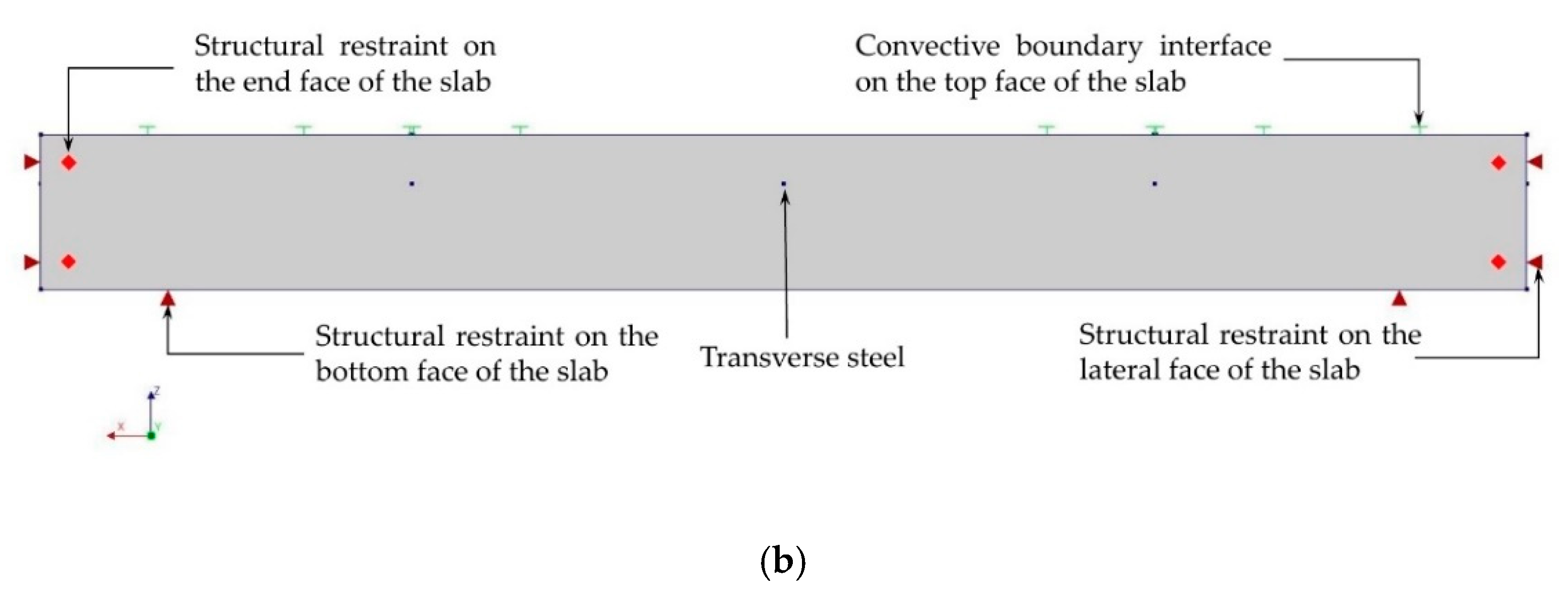
The structural and thermal aspects of the boundary conditions are defined with respect to the staggered structural-flow analysis. For the structural aspect, the bottom face of the concrete slab is restrained in an upward direction (Uz = 0), assuming a stiffer ground base layer beneath the concrete slab. By taking advantage of the symmetric conditions, the concrete slab is restrained in both the Y–Z planes and the symmetrical inner plane X–Z plane; however, the plane on the saw-cut side is free to expand and contract. It translates that the concrete slab on the symmetric planes can contract, but it cannot expand because of the infinite surrounding concrete. The contact interface between the bottom face of the concrete slab and ground base has been modeled using a nonlinear elastic friction model [55].
For the thermal boundary conditions, the slab top face and the outer edge face on the saw-cut side are directly exposed to external varying temperature field conditions, as demonstrated in Figure 8. Considering the potential heat flow analysis, the convective interface boundary elements are used to simulate the heat transfer through the concrete slab and the outside environment. The value of the heat transfer coefficient is assumed as 7.5 W/m2 °C based on previous studies [43,51,56,57]. The proposed boundary conditions of the FE model are shown in Figure 9.

4.4. Elements Used in FE Modeling

For the 3D heat flow analysis, a four-node isoparametric quadrilateral element (BQ4HT) is commonly used to define the convective interface boundaries. The exposed surfaces of the concrete slab subjected to heat convection, as shown in Figure 9, are modeled using this four-node quadrilateral element. The concrete was discretized through a 20-node isoparametric solid brick element (CHX60). The contact interface between the bottom face of the concrete slab and ground base is modeled using an eight-node element (CQ481) with interface elements of zero-thickness. The accuracy of the FE analysis depends on the size and characteristics of the element in the mesh. The element size is taken as 30 mm based on the mesh sensitivity analysis.

4.5. Cracking Model Used in FE Modeling

The smeared cracking approach is mostly employed to simulate the cracking behavior of concrete members. This approach treats the cracked material as continuous and spreads the discontinuity of displacement field caused by crack across the element through the constitutive equations following the crack development in the element [45,58]. The concrete cracks when the tensile stress exceeds its tensile strength.

5. Validation of the FE Model

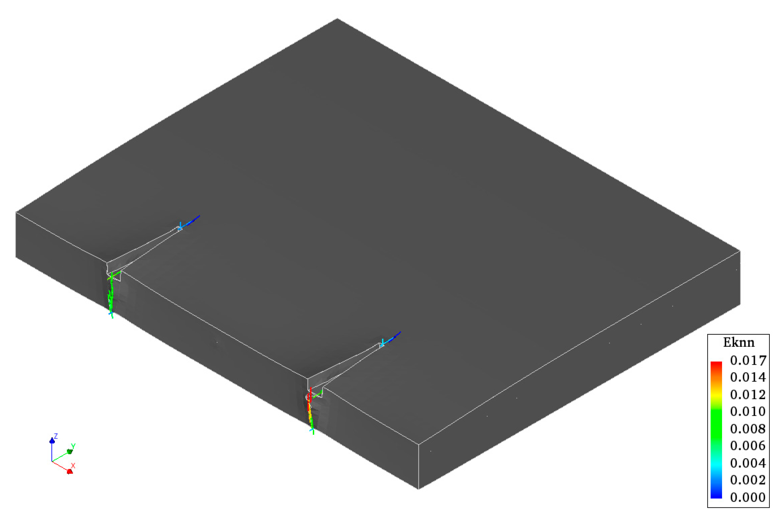
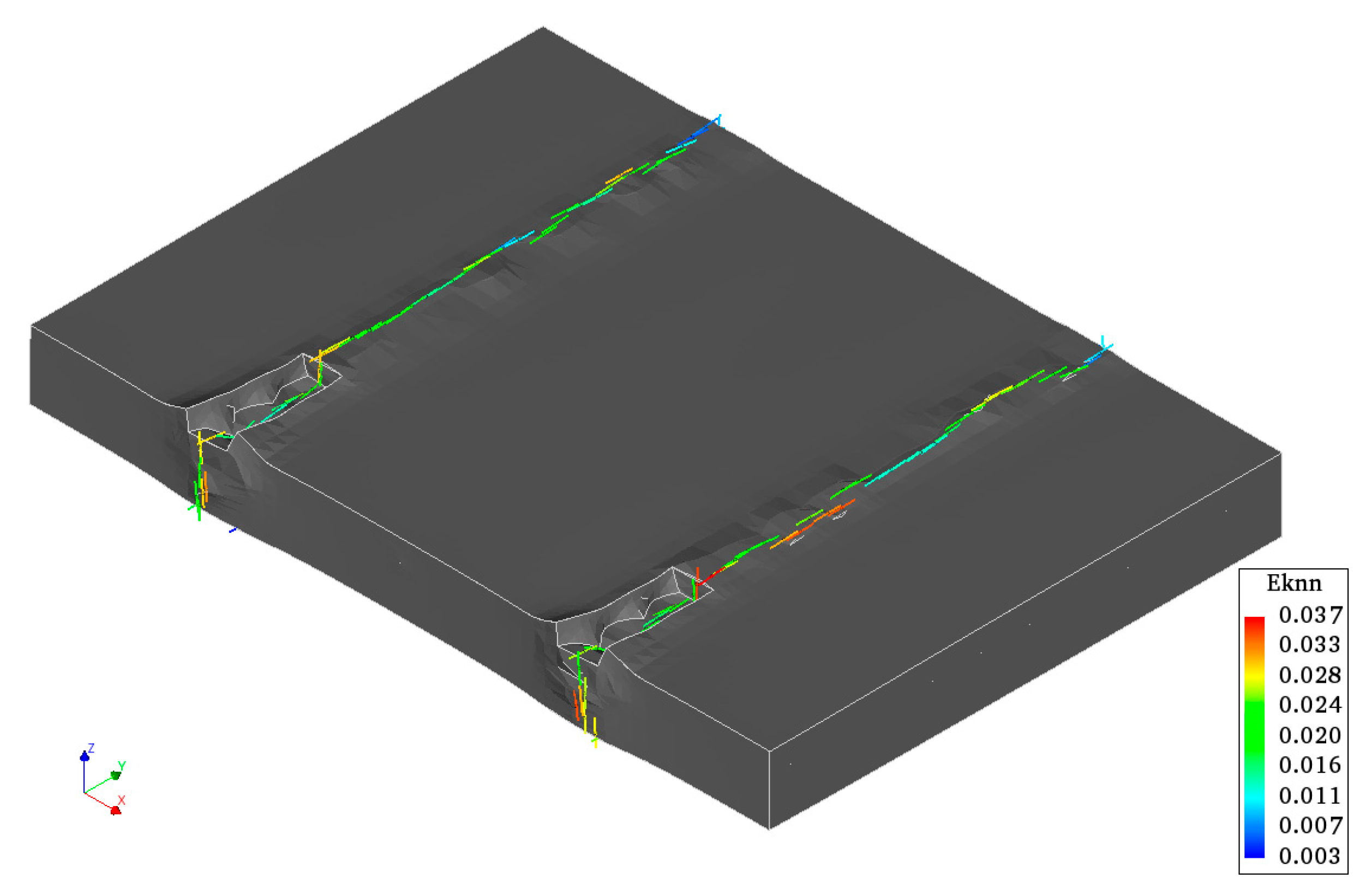
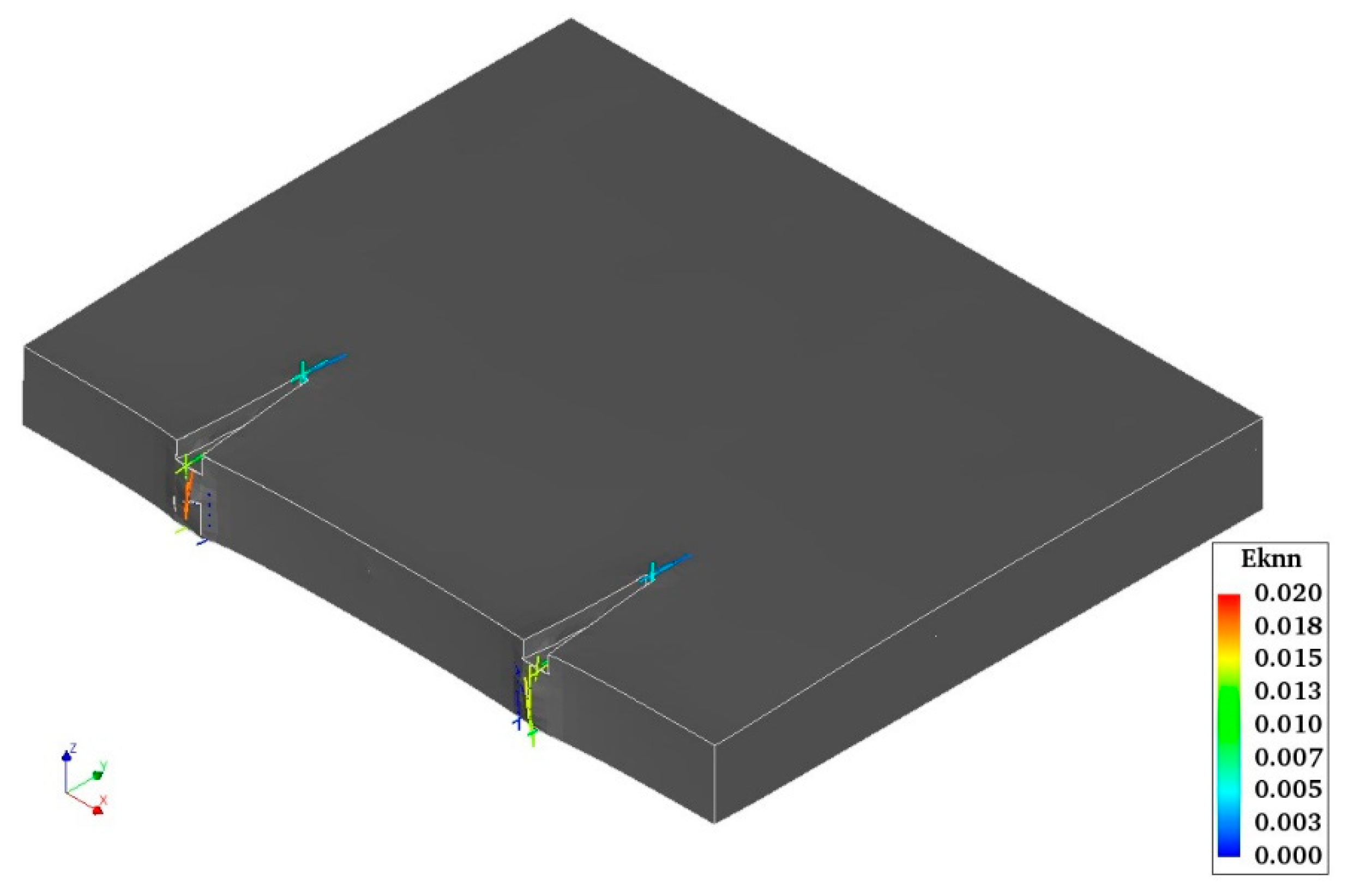
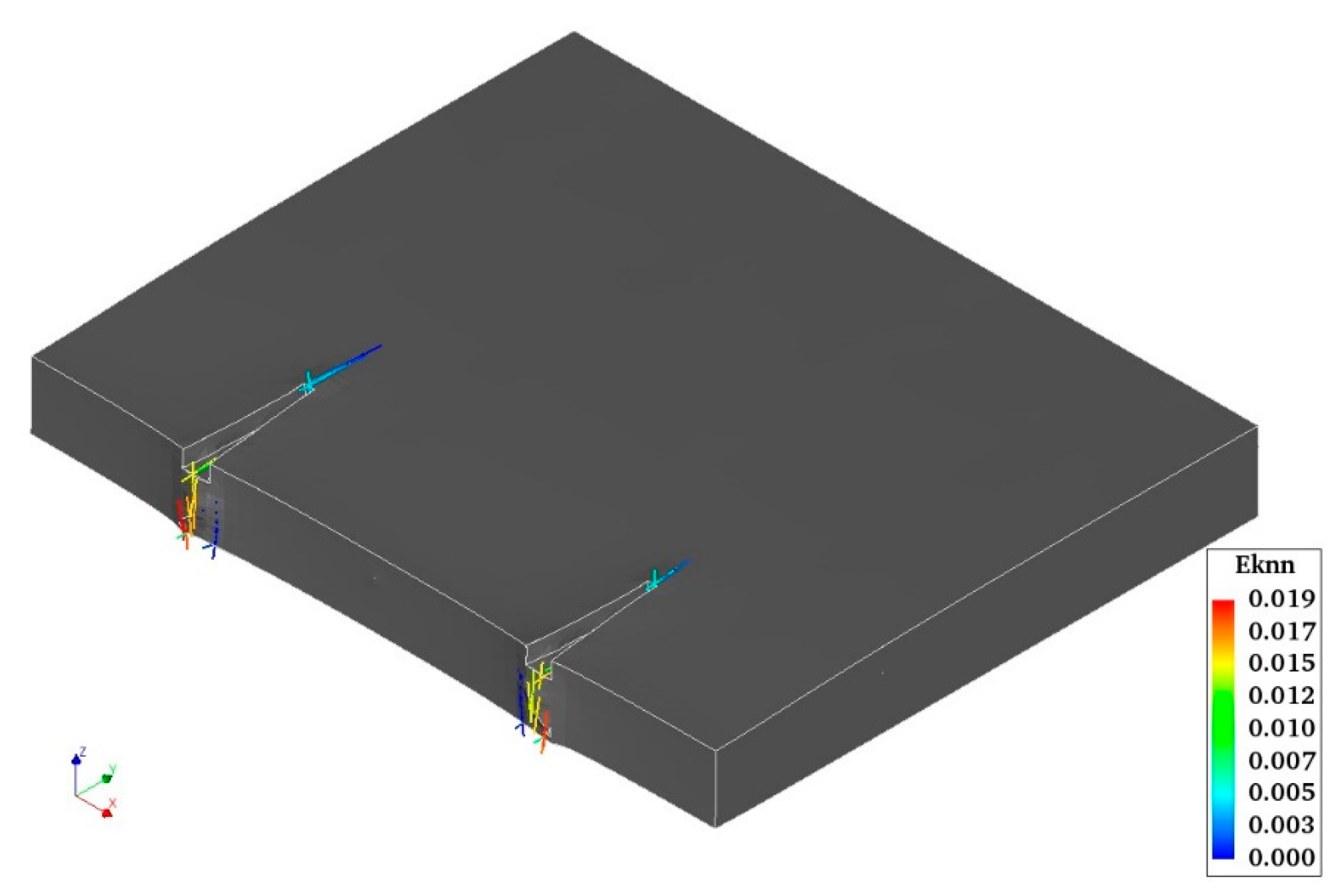
The partial surface saw-cuts in CRCP are originally intended to induce cracking from pre-defined positions (saw-cut tips), which ultimately results in the formation of a more regular spaced crack pattern, as demonstrated in Figure 5 [12,13,26,27]. The same configuration of saw-cuts applied in the field test sections on Motorway E313, as discussed in Section 3, was used in the reference FE model to simulate the crack induction. As expected, the saw-cut tips exhibit the maximum tensile stress compared with the rest of the concrete slab. The development of tensile stress is plotted against tensile strength over the saw-cut tips along the length of the concrete slab, as shown in Figure 10. The tensile stress exceeds tensile strength exactly over the saw-cut tips. Hence, crack induction occurs from the saw-cut tips, as illustrated in Figure 11. The crack propagation along the width of the concrete slab is demonstrated in Figure 12. “Eknn”, shown in Figure 11 and Figure 12, represents the crack strain. It can clearly be observed that cracks initiate exactly from the tips of the saw-cut and propagate along the pavement width, as observed on the E313 test section discussed above in Section 3. The same transverse crack pattern as illustrated in Figure 5 is predicted by the FE model.
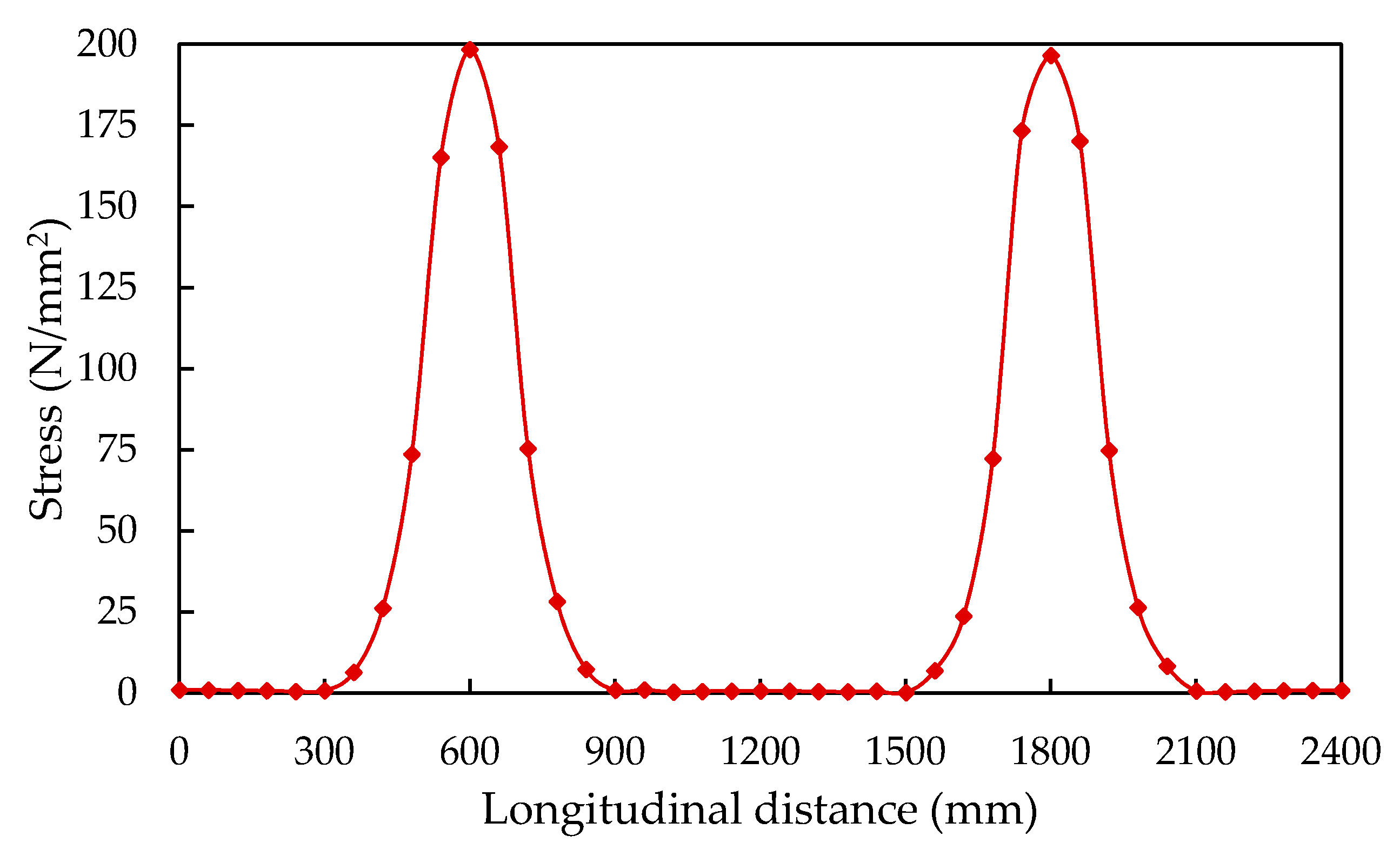
The third longitudinal steel bar just ahead of the saw-cut tips is selected for evaluating the stress distribution in the steel bar. The development of maximum steel stress distribution along the length of the steel bar is depicted in Figure 13. It can clearly be noticed that the steel bar exhibits the maximum stress exactly below the position of saw-cuts. These findings indicate that the proposed methodology and assumptions in the development of the reference FE model are appropriate for evaluating early-age crack induction in CRCP under environmental loading.
Furthermore, the early-age crack induction in the CRCP segment without partial surface saw-cuts is also evaluated and a comparison is made with the field observations of cracking development on the Motorway E17 test section. The observed crack pattern was characterized as the cluster of closely spaced cracks, as discussed in Section 3. Figure 14 illustrates the crack induction in CRCP predicted by the FE model without saw-cuts. The same crack pattern with cluster crack formations is induced as indicated by field observations as shown in Figure 3. The FE model with and without saw-cuts predicts the same crack induction as observed on the CRCP test sections of Motorway E313 and E17. Based on these findings, it may be assumed that the reference FE model developed with appropriate considerations could be further used to advance the structural design concept of CRCP.

6. Reinforcement Layout Design of ARCP Segment

As the fundamental behavior of ARCP is the same as that of CRCP even though a lesser amount of steel is used in ARCP [37], the dimensions of the ARCP segment along with the position of partial surface saw-cuts are taken as the same as that of CRCP, as discussed in Section 4. In the ARCP design, partial steel bars are used to replace continuous longitudinal steel bars under the crack inducer to minimize the excess amount of steel in the pavement. The continuous steel bars in between the actively induced cracks are intended to hold freely formed cracks, as illustrated in Figure 15. Based on the steel stress distribution illustrated in Figure 13 and the design spacing of partial saw-cuts, the total length of the partial steel bar is assumed to be 600 mm. Two reinforcement layouts are considered for evaluating the effect of partial steel bars on the early-age cracking behavior of ARCP. In the first layout, the continuous longitudinal steel bars are alternatively replaced with partial steel bars, as demonstrated in Figure 16, which is named ARCP-1. Meanwhile, the second layout is comprised of replacing two consecutive continuous longitudinal steel bars with partial steel bars, as illustrated in Figure 17, which is named ARCP-2. The comparison of reinforcement layout design used in the CRCP and ARCP segments is demonstrated in Table 5.

7. Results and Discussion

The early-age cracking behavior of CRCP without the active crack control method is categorized as the randomly occurring crack pattern [12,13,20,44]. The key factor affecting the development of early-age cracking in CRCP is the resistance to the change in length of the concrete slab [59]. The performance of CRCP is largely determined by the early-age cracking development [10,11,12,13,44]. It has been reported that about 90% of punch-out distress on CRCP sections was triggered by clusters of randomly occurring cracks [60]. The thorough saw-cut across the full width of pavement and automated tape insertion illustrate some drawbacks, such as issues related to concrete surface spalling [11,12,14]. The behavior of ARCP is dependent on the effectiveness of the crack induction strategy in inducing cracks at the desired locations where the partial length steel bars are originally intended to replace the continuous longitudinal steel bars. Two major shortcomings of passive crack control CRCP (without any active crack control method), that is, the high initial construction cost and non-uniform crack patterns, are discussed to be resolved with the concept of ARCP by using automated tape insertion as a crack induction strategy [37]. As discussed above, this strategy has already been applied to CRCP as an active crack control method and its associated demerits have also been discussed.
Regarding the performance of active crack control CRCP using partial surface saw-cuts, as discussed above in Section 3, only one shortcoming of CRCP, that is, the high initial construction cost, is left to be resolved by using partial length steel bars in place of continuous longitudinal steel bars. Based on this fact, the fundamental behavior of ARCP is basically equivalent to that of CRCP. Therefore, in the present study, the early-age cracking behavior of ARCP with partial surface saw-cuts is evaluated with respect to the amount of continuous steel and compared with that of CRCP.
The crack induction from the tips of saw-cuts in ARCP-1 and ARCP-2, shown in Figure 18 and Figure 19, illustrates that ARCP behaves exactly as CRCP, as discussed in the Section 5. The predicted crack patterns of ARCP-1 and ARCP-2 depicted in Figure 20 and Figure 21 are also basically the same as those exhibited by CRCP depicted in Figure 12 and as indicated by field observations illustrated in Figure 5. This finding indicates that the transverse crack pattern with desirable crack spacing (1.2 m) could be effectively induced in ARCP by using partial surface saw-cuts.
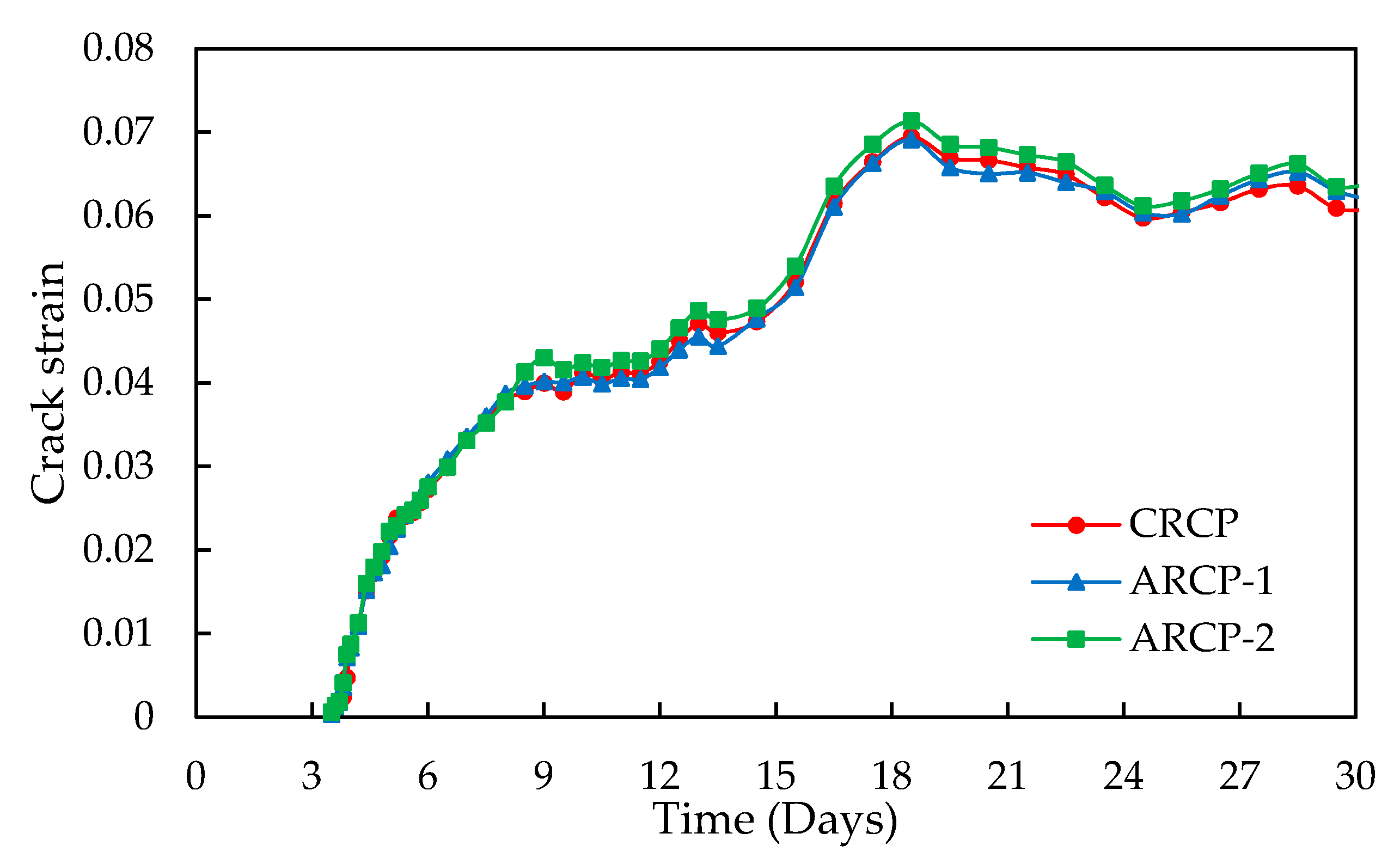
Moreover, the development of crack strain with respect to time over the saw-cut tips demonstrated in Figure 22 illustrates no prominent difference between CRCP and ARCP. Based on the field observations of cracking developments discussed above, it may justify the lesser amount of continuous steel bars in the active crack control ARCP segment in between the saw-cuts to hold the passively formed cracks tightly between the actively induced cracks. Hence, a considerable amount of initial construction cost could be reduced by eliminating the unnecessary longitudinal continuous steel bars in between the crack inducers (saw-cuts) without compromising the pavement performance.
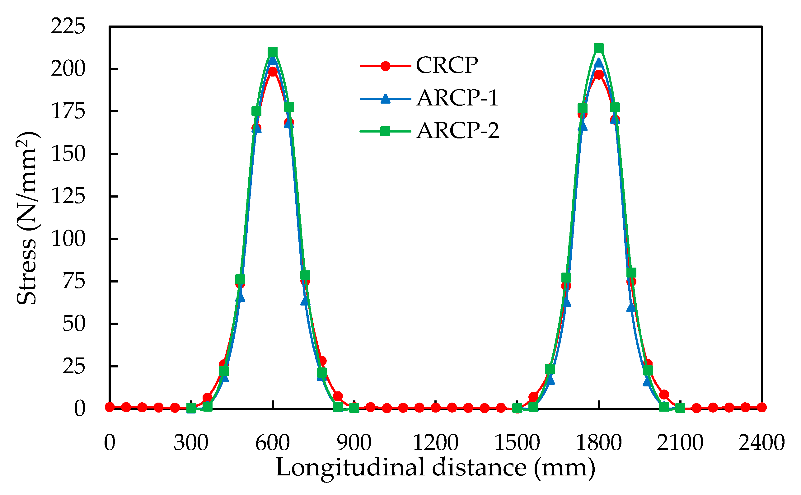
The longitudinal reinforcing steel bars in the CRCP and ARCP segments just ahead of saw-cut tips are selected for evaluating the maximum steel stress distribution. Figure 23 demonstrates the maximum steel stress distribution in the continuous steel bar of CRCP and partial steel bars of ARCP-1 and ARCP-2. It can clearly be observed that the steel stress peaks occur exactly over the saw-cut tips. In between the saw-cuts, the stress variations converge to zero, which indicates the effectiveness of the active crack control method to induce cracks at the desired locations. It may translate that the continuous steel bars between the crack inducers (saw-cuts) across the whole width of the concrete slab are unnecessary when no passive cracks are formed. As demonstrated in Figure 23, the continuous steel bar and partial steel bar experience the same stress peaks only over the saw-cut tips. This means that steel bars are only required at crack locations to hold the actively induced cracks tightly and a lesser amount of the steel bars is required for any randomly occurring cracks between the crack inducers. Although a considerable amount of continuous steel bars, up to about 45% and 63% in ARCP-1 and ARCP-2 in relative comparison to that of CRCP, is reduced, the steel stress distributions in ARCP are almost similar to those in CRCP, as shown in Figure 23. Therefore, it may be stated that the behavior of ARCP even with a relatively lesser amount of continuous reinforcement is basically the same as the behavior of CRCP under environmental loading.
As the overall configuration of the CRCP structure being used in Belgium is not quite different from that used in the United States and other parts of the world, the proposed ARCP structure can be applied in place of CRCP along with a relatively lower initial construction cost, subject to the extensive field trials.

8. Summary of Findings and Conclusions

The concept and design of ARCP are comprehensively explained with respect to the effectiveness of the crack induction strategy and the steel stress distributions. In the present study, two different reinforcement design layouts of ARCP are developed to reduce the amount of continuous longitudinal reinforcement up to about 45% to 63% relative to that of CRCP. Based on the steel stress distributions and design spacing of partial surface saw-cuts, the partial steel bar of 600 mm length is used in place of the continuous longitudinal steel bar across the pavement width at crack locations. The active crack control method in the form of partial surface saw-cuts at one of the top edges of the concrete slab is applied to induce cracks at the predetermined locations in ARCP. The crack initiation from the tips of saw-cuts and crack propagation across the pavement width indicate the appropriateness and effectiveness of active crack control for ARCP. The steel stress distributions in the partial steel bar of ARCP are quite similar to those in the continuous longitudinal steel bar of CRCP. The early-age crack induction in ARCP using partial surface saw-cuts is identical to that of CRCP under the same prevailing external environmental conditions. Based on these findings, it may be concluded that the concept of ARCP using partial surface saw-cuts as a crack induction strategy could be an effective solution to resolve the shortcomings of CRCP without compromising the fundamental behavior of CRCP. This concept of ARCP using partial surface saw-cuts is quite a new development for the rigid pavement structure. Therefore, more extensive experimental and field investigations, as well as numerical studies, are required by considering traffic loading to formulate a more rational pavement structure.

Author Contributions

Conceptualization, M.K.; Writing—Original draft, M.K.; Supervision, H.D.B.; Writing—Review & editing, A.N., N.I., and P.D.W. All authors have read and agreed to the published version of the manuscript.

Funding

The funding for this research along with the article processing charges (APC) have been provided by the Higher Education Commission (HEC) of Pakistan under the grant of UESTP-HRDI initiative.

Acknowledgments

In the corresponding author gratefully acknowledges financial support from the Higher Education Commission (HEC), Pakistan.

Conflicts of Interest

The authors declare no conflict of interest.

References

  1. Safiuddin, M.; Kaish, A.; Woon, C.-O.; Raman, S.N. Early-age cracking in concrete: Causes, consequences, remedial measures, and recommendations. Appl. Sci. 2018, 8, 1730. [Google Scholar] [CrossRef] [Green Version]
  2. Guo, S.; Dai, Q.; Hiller, J. Investigation on the freeze-thaw damage to the jointed plain concrete pavement under different climate conditions. Front. Struct. Civ. Eng. 2018, 12, 227–238. [Google Scholar] [CrossRef]
  3. Jung, Y.S.; Zollinger, D.G.; Ehsanul, B.M. Improved Mechanistic–Empirical Continuously Reinforced Concrete Pavement Design Approach with Modified Punchout Model. Transp. Res. Rec. 2012, 2305, 32–42. [Google Scholar] [CrossRef]
  4. Lee, S.W.; Stoffels, S.M. Effects of excessive pavement joint opening and freezing on sealants. J. Transp. Eng. 2003, 129, 444–450. [Google Scholar] [CrossRef]
  5. Saghafi, B.; Hassani, A.; Noori, R.; Bustos, M.G. Artificial neural networks and regression analysis for predicting faulting in jointed concrete pavements considering base condition. Int. J. Pavement Res. Technol. 2009, 2, 20–25. [Google Scholar]
  6. Vennapusa, P.K.; White, D.J. Field assessment of a jointed concrete pavement foundation treated with injected polyurethane expandable foam. Int. J. Pavement Eng. 2015, 16, 906–918. [Google Scholar] [CrossRef]
  7. Yao, J.-L.; Weng, Q.-h. Causes of longitudinal cracks on newly rehabilitated jointed concrete pavements. J. Perform. Constr. Facil. 2012, 26, 84–94. [Google Scholar] [CrossRef]
  8. Darter, M.I.; LaCoursiere, S.A.; Smiley, S.A. Structural Distress Mechanisms in Continuously Reinforced Concrete Pavement. Transp. Res. Rec. 1979, 715, 1–7. [Google Scholar]
  9. Hall, K.; Dawood, D.; Vanikar, S.; Tally, R., Jr.; Cackler, T.; Correa, A.; Deem, P.; Duit, J.; Geary, G.; Gisi, A. Long-Life Concrete Pavements in Europe and Canada; The National Academies of Sciences, Engineering, and Medicine: Washington, DC, USA, 2007. [Google Scholar]
  10. Kohler, E.; Roesler, J. Crack Width Determination in Continuously Reinforced Concrete Pavements. In Proceedings of the Second International Conference on Accelerated Pavement Testing, Minneapolis, MN, USA, 26–29 September 2004. [Google Scholar]
  11. Kohler, E.; Roesler, J. Active crack control for continuously reinforced concrete pavements. Transp. Res. Rec. 2004, 1900, 19–29. [Google Scholar] [CrossRef]
  12. Ren, D. Optimisation of the Crack Pattern in Continuously Reinforced Concrete Pavements. Ph.D. Thesis, Technische Universiteite Delft, Delft, The Netherlands, 2015. [Google Scholar]
  13. Ren, D.; Houben, L.; Rens, L.; Beeldens, A. Active Crack Control for Continuously Reinforced Concrete Pavements in Belgium Through Partial Surface Notches. Transp. Res. Rec. 2014, 2456, 33–41. [Google Scholar] [CrossRef]
  14. Zollinger, D.G.; Buch, N.; Xin, D.; Soares, J. Performance of CRCP Volume 6-CRCP Design, Construction, and Performance; FHWA-RD-97-151; FHWA: Washington, DC, USA, 1998.
  15. De Winne, P.; De Backer, H.; Depuydt, S. Active Crack Control in Continuously Reinforced Concrete Pavements (CRCP). In High Tech Concrete: Where Technology and Engineering Meet; Springer: Berlin/Heidelberg, Germany, 2018; pp. 1389–1397. [Google Scholar]
  16. Kang, Y.-J.; Park, J.; Yoon, K.-Y.; Han, S.-Y. Experimental study on fatigue strength of continuously reinforced concrete pavements. Mag. Concr. Res. 2004, 56, 605–615. [Google Scholar] [CrossRef]
  17. Oh, H.J.; Cho, Y.K.; Kim, S.-M. Experimental evaluation of crack width movement of continuously reinforced concrete pavement under environmental load. Constr. Build. Mater. 2017, 137, 85–95. [Google Scholar] [CrossRef]
  18. Oh, H.J.; Cho, Y.K.; Seo, Y.; Kim, S.-M. Experimental analysis of curling behavior of continuously reinforced concrete pavement. Constr. Build. Mater. 2016, 128, 57–66. [Google Scholar] [CrossRef]
  19. Oh, H.J.; Cho, Y.K.; Seo, Y.; Kim, S.-M. Experimental evaluation of longitudinal behavior of continuously reinforced concrete pavement depending on base type. Constr. Build. Mater. 2016, 114, 374–382. [Google Scholar] [CrossRef]
  20. Ren, D.; Houben, L.J.; Rens, L. Monitoring Early-Age Cracking of Continuously Reinforced Concrete Pavements on the E17 at Ghent (Belgium). In Sustainable Construction Materials 2012; ASCE: Reston, VA, USA, 2013; pp. 30–41. [Google Scholar]
  21. Rens, L. Continuously Reinforced Concrete-State-of-the-Art in Belgium. In Proceedings of the 11th International Symposium on Concrete Roads, Padua, Italy, 11–13 September 2019. [Google Scholar]
  22. Rens, L.; Beeldens, A. The Behaviour of CRCP in Belgium: Observation and Measurement of Crack Pattern, Bond and Thermal Movement. In Proceedings of the 7th International DUT-Workshop on Design and Performance of Sustainable and Durable Concrete Pavements, Seville, Spain, 10–11 October 2010. [Google Scholar]
  23. Rens, L.; Winne, P.; Beeldens, A. Continuously Reinforced Concrete Pavement: New Development for a Sustainable Concept. In Proceedings of the Belgian Road Congress, Liege, Belgium, 29 July 2016. [Google Scholar]
  24. Verhoeven, K. Cracking and Corrosion in Continuously Reinforced Concrete Pavements. In Proceedings of the Fifth International Conference on Concrete Pavement Design and Rehabilitation, West Lafayette, IN, USA, 20–22 April 1993. [Google Scholar]
  25. Choi, S.; Ha, S.; Won, M.C. Horizontal cracking of continuously reinforced concrete pavement under environmental loadings. Constr. Build. Mater. 2011, 25, 4250–4262. [Google Scholar] [CrossRef]
  26. Kashif, M.; De Winne, P.; Naseem, A.; Iqbal, N.; De Backer, H. Three Dimensional Finite Element Model for Active Crack Control in Continuously Reinforced Concrete Pavement. In Proceedings of the 9th International Conference on Maintenance and Rehabilitation of Pavements—Mairepav9; Springer: Cham, Switzerland, 2020. [Google Scholar]
  27. Kashif, M.; Naseem, A.; Iqbal, N.; Winne, P.D.; De Backer, H. Numerical Evaluation of Early-Age Crack Induction in Continuously Reinforced Concrete Pavement with Different Saw-Cut Dimensions Subjected to External Varying Temperature Field. Appl. Sci. 2020, 11, 42. [Google Scholar] [CrossRef]
  28. Mirsayar, M.; Zollinger, D. Factors influencing stresses and movements in continuously reinforced concrete pavements—A review. Eng. Solid Mech. 2018, 6, 67–82. [Google Scholar] [CrossRef]
  29. Ryu, S.W.; Choi, P.; Choi, S.; Won, M.C. Improvements of Full-Depth Repair Practices for Distresses in Continuously Reinforced Concrete Pavement. Transp. Res. Rec. 2013, 2368, 102–113. [Google Scholar] [CrossRef]
  30. Selezneva, O.; Darter, M.; Zollinger, D.; Shoukry, S. Characterization of transverse cracking spatial variability: Use of long-term pavement performance data for continuously reinforced concrete pavement design. Transp. Res. Rec. 2003, 1849, 147–155. [Google Scholar] [CrossRef]
  31. Suh, Y.-C.; Hankins, K.D.; McCullough, B.F. Early-Age Behavior Continuously Reinforced Concrete Pavement and Calibration the Failure Prediction Model in the CRCP-7 Program; Center for Transportation Research: Austin, TX, USA, 1992. [Google Scholar]
  32. Suh, Y.-C.; McCullough, B.F.; Hankins, K.D. Development and application of randomness index for continuously reinforced concrete pavement. Transp. Res. Rec. 1991, 1307, 136–142. [Google Scholar]
  33. Chen, D.-H.; Lin, H.-H.; Sun, R. Field performance evaluations of partial-depth repairs. Constr. Build. Mater. 2011, 25, 1369–1378. [Google Scholar] [CrossRef]
  34. Chorzepa, M.G.; Johnson, C.; Durham, S.; Kim, S.S. Forensic Investigation of Continuously Reinforced Concrete Pavements in Fair and Poor Condition. J. Perform. Constr. Facil. 2018, 32, 04018031. [Google Scholar] [CrossRef]
  35. Citir, N.; Durham, S.A.; Chorzepa, M.G.; Sonny Kim, S. Investigation of Factors Affecting Distresses on Continuously Reinforced Concrete Pavement using Ground Penetrating Radar. J. Perform. Constr. Facil. 2020, 34, 04020027. [Google Scholar] [CrossRef]
  36. Kim, K.; Han, S.; Tia, M.; Greene, J. Optimization of parameters affecting horizontal cracking in continuously reinforced concrete pavement (CRCP). Can. J. Civ. Eng. 2019, 46, 634–642. [Google Scholar] [CrossRef]
  37. Kim, S.-M.; Cho, Y.K.; Lee, J.H. Advanced reinforced concrete pavement: Concept and design. Constr. Build. Mater. 2020, 231, 117130. [Google Scholar] [CrossRef]
  38. Kim, S.-M.; Won, M.; Frank McCullough, B. Numerical modeling of continuously reinforced concrete pavement subjected to environmental loads. Transp. Res. Rec. 1998, 1629, 76–89. [Google Scholar] [CrossRef]
  39. Kim, S.-M.; Won, M.C. Horizontal cracking in continuously reinforced concrete pavements. Struct. J. 2004, 101, 784–791. [Google Scholar]
  40. McCullough, B.F.; Dossey, T. Considerations for high-performance concrete paving: Recommendations from 20 years of field experience in Texas. Transp. Res. Rec. 1999, 1684, 17–24. [Google Scholar] [CrossRef]
  41. Al-Qadi, I.L.; Elseifi, M. Mechanism and modeling of transverse cracking development in continuously reinforced concrete pavement. Int. J. Pavement Eng. 2006, 7, 341–349. [Google Scholar] [CrossRef]
  42. Kim, S.-M.; Won, M.C.; Frank McCullough, B. Three-dimensional analysis of continuously reinforced concrete pavements. Transp. Res. Rec. 2000, 1730, 43–52. [Google Scholar] [CrossRef]
  43. Sofi, M.; Lumantarna, E.; Mendis, P.; Zhong, A. Thermal Stresses of Concrete at Early Ages. J. Mater. Civ. Eng. 2019, 31, 04019056. [Google Scholar] [CrossRef]
  44. Ren, D.; Houben, L.; Rens, L. Cracking behavior of continuously reinforced concrete pavements in Belgium: Characterization of current design concept. Transp. Res. Rec. 2013, 2367, 97–106. [Google Scholar] [CrossRef]
  45. DIANA FEA BV. DIANA User’s Manual Release 10.3; DIANA FEA BV: Delft, The Netherlands, 2017. [Google Scholar]
  46. Choi, S.; Na, B.-U.; Won, M.C. Mesoscale analysis of continuously reinforced concrete pavement behavior subjected to environmental loading. Constr. Build. Mater. 2016, 112, 447–456. [Google Scholar] [CrossRef]
  47. Neville, A.M.; Brooks, J.J. Concrete Technology; Longman Scientific & Technical: London, UK, 1987. [Google Scholar]
  48. Byfors, J. Plain concrete at early ages. CBI Forsk 1980, 2, 465. [Google Scholar]
  49. Khan, A.A.; Cook, W.D.; Mitchell, D. Thermal properties and transient thermal analysis of structural members during hydration. Mater. J. 1998, 95, 293–303. [Google Scholar]
  50. Morabito, P. Thermal Properties of Concrete: Variations with the Temperature and During the Hydration Phase; Department of Civil Minining Engeneering: Milan, Italy, 2001. [Google Scholar]
  51. Saeed, M.K.; Rahman, M.K.; Baluch, M.H. Early age thermal cracking of mass concrete blocks with Portland cement and ground granulated blast-furnace slag. Mag. Concr. Res. 2016, 68, 647–663. [Google Scholar] [CrossRef]
  52. Emanuel, J.H.; Hulsey, J.L. Prediction of the thermal coefficient of expansion of concrete. Proc. J. Proc. 1977, 74, 149–155. [Google Scholar]
  53. Glasser, F. Chemical, mineralogical and Micro-structural Changes Occurring in Hydrated Slag-Cement Blends. Mater. Sci. Concr. 1991, 52, 41–82. [Google Scholar]
  54. Hendriks, M.A.; Rots, J. Finite Elements in Civil Engineering Applications: Proceedings the Third DIANA World Conference, Tokyo, Japan, 9–11 October 2002; CRC Press: Boca Raton, FL, USA, 2002. [Google Scholar]
  55. Narin, F.; Wiklund, O. Design of Slabs-on-Ground Regarding Shrinkage Cracking. 2012. Available online: http://publications.lib.chalmers.se/records/fulltext/165126.pdf (accessed on 11 July 2020).
  56. Faria, R.; Azenha, M.; Figueiras, J.A. Modelling of concrete at early ages: Application to an externally restrained slab. Cem. Concr. Compos. 2006, 28, 572–585. [Google Scholar] [CrossRef]
  57. Sofi, M.; Mendis, P.; Baweja, D.; Mak, S. Influence of ambient temperature on early age concrete behaviour of anchorage zones. Constr. Build. Mater. 2014, 53, 1–12. [Google Scholar] [CrossRef]
  58. Rots, J.G. Computational Modeling of Concrete Fracture. Ph.D. Thesis, Delft University of Technology, Delft, The Netherlands, September 1988. [Google Scholar]
  59. McCullough, B.F.; Treybig, H.J. Determining the Relationship of Variables in Deflection of Continuously-Reinforced Concrete Pavement. Highw. Res. Rec. 1966, 131, 65–86. [Google Scholar]
  60. Tsai, Y.J.; Wang, Z. Critical Assessment I-85 CRCP Crack Spacing Patterns and Their Implications for Long-Term Performance; Georgia Department of Transportation, Office of Research: Tbilisi, Georgia, 2014.
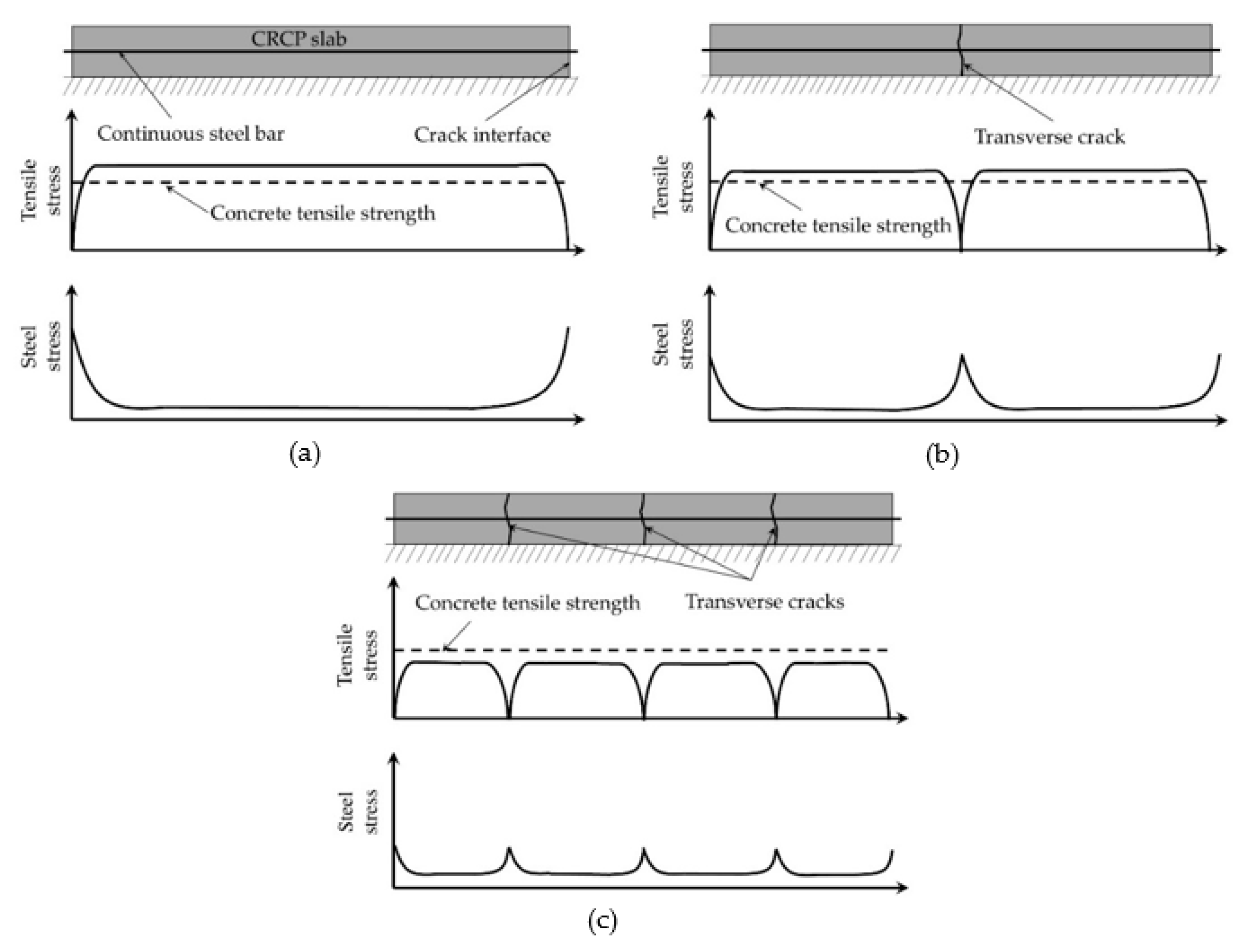
Figure 1. Cracking development in continuously reinforced concrete pavement (CRCP): (a) crack initiation; (b) crack propagation; and (c) fully developed crack pattern.
Applsci 11 01659 g001
Figure 2. Cracking development in advanced reinforced concrete pavement (ARCP) with (a) partial length steel bars and (b) continuous steel bar.
Applsci 11 01659 g002
Figure 3. Passive crack development on the Motorway E17 section.
Applsci 11 01659 g003
Figure 4. Partial surface saw-cut at the outer edge of the concrete slab.
Applsci 11 01659 g004
Figure 5. Active crack development on the Motorway E313 section.
Applsci 11 01659 g005
Figure 6. Comparison of cumulative crack spacing distribution between active crack control and passive crack control CRCP sections.
Applsci 11 01659 g006
Figure 7. Geometry details of the CRCP segment.
Applsci 11 01659 g007
Figure 8. External varying temperature field.
Applsci 11 01659 g008
Figure 9. Boundary conditions of the FE model: (a) thermal boundary and (b) structural boundary.
Applsci 11 01659 g009aApplsci 11 01659 g009b
Figure 10. Development of maximum tensile stress against tensile strength over the saw-cut tips along the length of the pavement.
Applsci 11 01659 g010
Figure 11. Crack initiation in CRCP from the saw-cuts.
Applsci 11 01659 g011
Figure 12. The predicted transverse crack pattern of CRCP.
Applsci 11 01659 g012
Figure 13. Stress variation in the longitudinal steel bar.
Applsci 11 01659 g013
Figure 14. Development of the randomly occurring crack pattern in the CRCP segment without partial surface saw-cuts.
Applsci 11 01659 g014
Figure 15. Demonstration of reinforcement layout of ARCP.
Applsci 11 01659 g015
Figure 16. Reinforcement layout of ARCP-1.
Applsci 11 01659 g016
Figure 17. Reinforcement layout of ARCP-2.
Applsci 11 01659 g017
Figure 18. Crack initiation in ARCP-1 from the saw-cuts.
Applsci 11 01659 g018
Figure 19. Crack initiation in ARCP-2 from the saw-cuts.
Applsci 11 01659 g019
Figure 20. The predicted transverse crack pattern of ARCP-1.
Applsci 11 01659 g020
Figure 21. The predicted transverse crack pattern of ARCP-2.
Applsci 11 01659 g021
Figure 22. Comparison of crack strain over the saw-cut tips between CRCP and ARCP.
Applsci 11 01659 g022
Figure 23. Comparison of maximum steel stress distribution between CRCP and ARCP.
Applsci 11 01659 g023
Table 1. Overview of design concepts for continuously reinforced concrete pavement (CRCP) in Belgium.
Design ConceptConcept 1Concept 2Concept 3
Time period1970–19811981–19951995–onwards
Longitudinal reinforcement0.85% (Ø18@150 mm)0.67% (Ø16@150 mm)0.75% (Ø20@170 mm)
Cover depth60 mm90 mm80 mm
Slab thickness200 mm200 mm230/250 mm
Asphalt interlayerYes, 60 mmNoYes, 50 mm
Table 2. Active crack characteristics on the Motorway E313 section [12,13].
Road SectionLength
(m)
Age (Days)No. of Notches (N1)No. of Cracks (N2)No. of Cracks at Notches (N3)Effectiveness of Notches N3/N1 (%)Percentage of Cracks in Category by Distance to Nearest Notch (m)
00–0.20.2–0.40.4–0.6
60 mm1100489719319121.398.9001.1
11006589766455561.983.52.47.76.4
110020489776259766.678.43.89.88.0
110037889777560667.678.23.89.98.1
50012342241724558.158.79.415.916.0
30 mm50026242249728166.556.58.717.517.3
50043642250228567.556.88.617.317.3
Table 3. Input parameters used in the finite element (FE) simulation.
Concrete classC40/50
Aggregate typeLimestone
Coefficient of thermal expansion of concrete (1/°C)10.0 × 10−6
Concrete thermal conductivity (W/m °C)2.7
Concrete volumetric heat specific capacity (J/m3 °C)2.87 × 10⁶
Convection-radiation coefficient between concrete and air (W/m2 °C)7.55
Table 4. Input parameter for Euro-code 2 EN 1992-1-1 creep and shrinkage model.
Input ParametersValue
Ambient temperature (°C)20
Notional size (mm)439
Relative humidity (%)80
Curing age (Days)3
Table 5. Comparison of reinforcement layout of CRCP and advanced reinforced concrete pavement (ARCP).
Steel DesignCRCPARCP-1ARCP-2
Diameter of continuous steel bar (mm)202020
Length of continuous steel bar (mm)240024002400
Rows of continuous steel bars1164
Continuous steel ratio (%)0.7670.4180.279
Diameter of partial steel bar (mm)-2020
Length of partial steel bar (mm)-600600
Rows of partial steel bars-57
Steel ratio at crack inducer (%)0.7670.7670.767
Relative continuous steel amount to CRCP (%)10054.5436.36
Publisher’s Note: MDPI stays neutral with regard to jurisdictional claims in published maps and institutional affiliations.