Article

Design for Additive Manufacturing: Tool Review and a Case Study

by
Daniel Moreno Nieto
1,* and
Daniel Moreno Sánchez
2
1
Departamento de Ingeniería Mecánica y Diseño Industrial, Escuela Superior de Ingeniería, Universidad de Cádiz, Puerto Real, 11510 Cádiz, Spain
2
Departamento de Ciencia de los Materiales e Ingeniería Metalúrgica y Química Inorgánica, Facultad de Ciencias, IMEYMAT, Campus Río San Pedro, Universidad de Cádiz, PuertoReal, 11510 Cádiz, Spain
*
Author to whom correspondence should be addressed.
Appl. Sci. 2021, 11(4), 1571; https://doi.org/10.3390/app11041571
Submission received: 11 January 2021 / Revised: 1 February 2021 / Accepted: 3 February 2021 / Published: 9 February 2021
(This article belongs to the Special Issue Design for Additive Manufacturing: Methods and Tools)

Abstract

:
This paper aims to collect in a structured manner different computer-aided engineering (CAE) tools especially developed for additive manufacturing (AM) that maximize the capabilities of this technology regarding product development. The flexibility of the AM process allows the manufacture of highly complex shapes that are not possible to produce by any other existing technology. This fact enables the use of some existing design tools like topology optimization that has already existed for decades and is used in limited cases, together with other novel developments like lattice design tools. These two technologies or design approaches demand a highly flexible manufacturing system to be applied and could not be used before, due to the conventional industrial process limitations. In this paper, these technologies will be described and combined together with other generic or specific design tools, introducing the study case of an additive manufactured mechanical design of a bicycle stem.

1. Introduction

Additive manufacturing (AM) is a set of manufacturing processes that consist in the generation of three-dimensional models from digital files, using different equipment and technologies that build objects layer by layer [1,2,3,4]. These technologies are reaching the age of maturity due to their effective incorporation in different industries, besides the pioneering aerospace and automotive industries, such as consumer products. There are many advantages that additive manufacturing technologies offer to designers and engineers for the development of new parts and products.
Advantages, the freedom of constructed geometries, which allows the elaboration of complex shapes that would not be possible by other technologies [5], the reduction of parts in the assemblies, by simplifying them or allowing the printing of the assembled parts [6,7,8], the capability of locating the necessary properties in specific areas or developing variable properties in the geometries of the parts and the possibility of manufacturing optimized structures that modify their properties according to the scale to which they refer, from the micro to the macro scale [9,10], are the most remarkable.
Through these advantages, additive manufacturing in the current state of development is increasingly finding its place in industry, while understanding that it is not a substitute technology, but rather complementary to current production technologies, in cases where some of the characteristics mentioned above are required. That is, it will take its place within the production processes and coexisting technologies, while having special importance in parts with highly complex geometries, in small series and in customized products.
The limitations of these processes have also been identified: the geometric characteristics (tolerances in the definition of wall thicknesses, holes, rounding, cantilevers, bridges and angles) and the anisotropy of the process that affects the mechanical properties of printed parts [11,12]. Those inherent to the execution of the process, such as the orientation of the part or the definition of the supports, deposition rates, finishes or production times, are decisive for the correct definition of the geometries [13,14,15], as well as other factors such as scale limitations, the absence of specific design and simulation tools and economic considerations. All these factors are related to the execution of the design for additive manufacturing [16,17].
Currently, new design prescriptions and standards are appearing, providing the designer a way to mitigate the limitations of the technologies and increase the functional performance of the final fabricated parts, known as design for additive manufacturing (DfAM) [18,19,20,21,22]. Some aspects to be considered and that are directly related with the manufacturing process are the disposition of holes that enable the evacuation of the residual material in the powder bed or liquid resin material or the deposition orientation in fused deposition modeling (FDM), for example.
In this context, in recent years, there has been an important advance in the field of specific engineering technologies for additive manufacturing, with the continuous appearance of numerous tools that consider the materials and their properties as variables, allowing for the prediction of their behavior and thus optimizing designs for manufacture. Prior to the description of these tools, we will review in a general way the main stages of the work process for the design and additive manufacturing of parts.

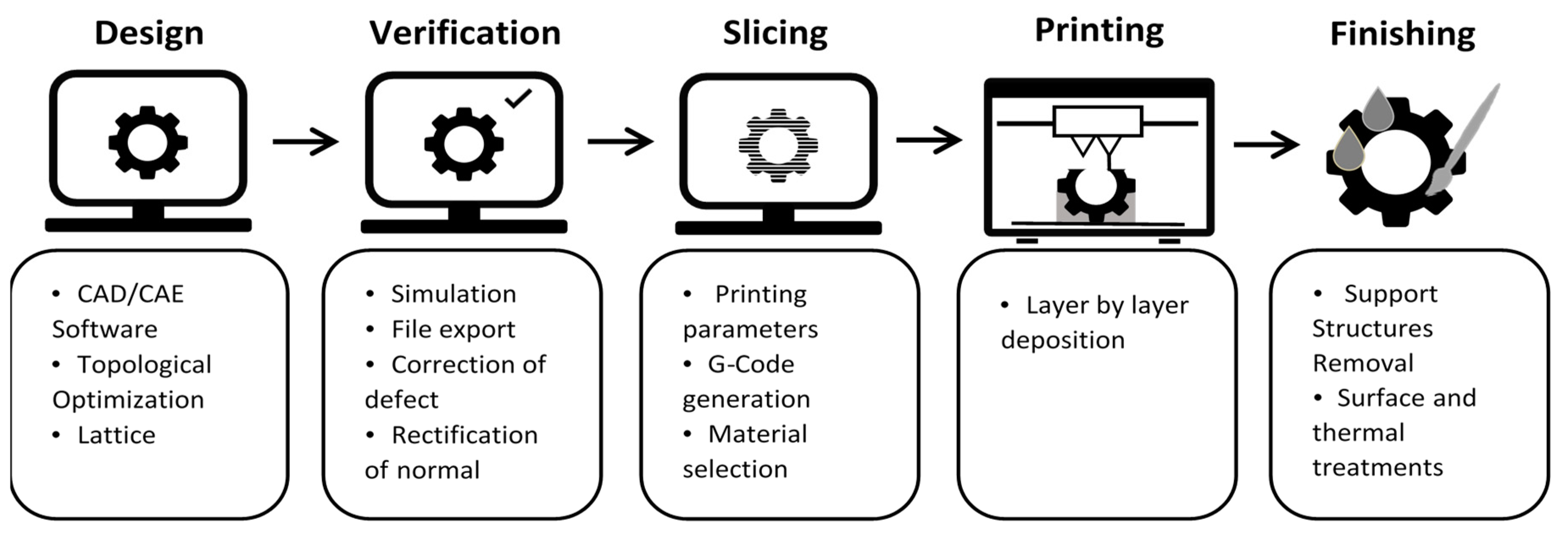
2. The Additive Manufacturing Workflow

The approach to the additive manufacturing processes establishes an orderly workflow, so that by relying on different tools, processing files are generated for subsequent printing and post-processing. There are five fundamental stages in the additive manufacturing process, which are listed below and shown in a diagram in Figure 1.
(a)
Design: For the development of the parts and products that will be manufactured by additive processes, the first stage consists of the generation of three-dimensional designs by means of computer-assisted design tools (CAD). The characteristics of the processes allow the generation of complex geometries, however, not all shapes are always viable and they are closely linked to the technology used. The construction of 3D models can be done with conventional solid and surface modeling programs; likewise, due to the flexibility of the process, the use of advanced modeling tools, such as polygonal meshes or NURBS surfaces, is very common.
(b)
Verification: Once the design process is completed, the next step is to export the files to the 3D printing standards. The most common file format is STL, which consists of a triangulated surface mesh that defines the complete geometry [23]. The export of files is done for their correct inclusion in the lamination tools or slicers. However, a previous step of surface verification is recommended, since sometimes discontinuities or incorrect orientations of the normals that define the surface triangles could be produced.
(c)
Slicing: The lamination programs or slicers previously mentioned are the tools that generate the machine code with the characteristics of the process and the parameters, as well as the trajectories. It is important to define the correct parameters of the process according to the characteristics of the design and materials. The main parameters shared by most processes are: layer height, manufacturing speed, temperature and percentage of filling. The result of this process definition is the machine path files, which are transferred to the printing equipment for process activation.
(d)
3D printing: This is the physical process in which the materialization of the parts using the 3D printers in question is done. Its characteristics vary depending on the technology selected. A common feature in all the technologies is that this is a long process and usually requires post-processing compared with traditional manufacturing processes such as injection molding.
(e)
Post-processing: Depending on the characteristics of the process, more or less intervention is necessary to achieve the specific finish and properties of the printed parts. Tasks common to all technologies are the removal of parts from the printing surface, the removal of supports and mechanical processes of surface finishing, as well as heat and surface treatments, if necessary.

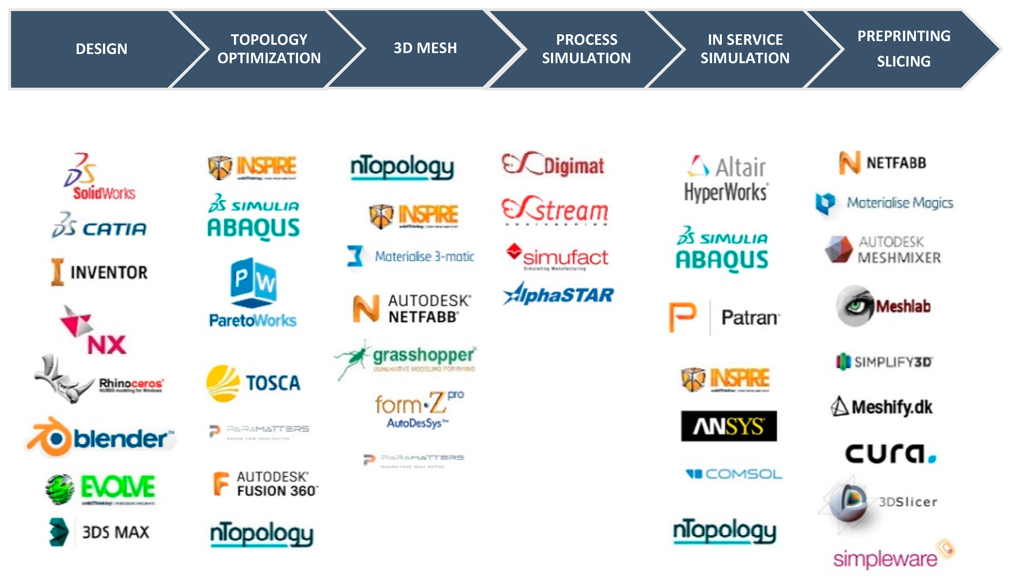
3. Additive Manufacturing Design Tools

In order to take advantage of and mitigate the limitations of these AM processes, different tools have appeared in recent years that maximize the potential of the constructive capabilities offered by additive manufacturing technologies. These programs consist of engineering and CAD platforms such as mesostructured design and optimization programs, along with process management and simulation solutions.
One of the main objectives set in the development of this work is to configure an updated workflow, ordered and structured to optimize processes from the integration and exchange of files, as well as to maximize the potential of the possibilities of forming that AM technologies present, supported by these specific tools.
In Figure 2 is presented different CAD and computer-aided engineering (CAE) tools currently available for the AM design process. Some of these programs previously existed on the market and have been adapted to these technologies, as well as other new specific tools that are appearing as the development and implementation of them advance.
Within the software tools, in addition to the traditional CAD programs, such as parametric design programs, e.g., Catia and Solidworks (Dassault Systèmes, Vélizy-Villacoublay, France), Inventor (Autodesk, San Rafael, CA, USA) or NX (Siemens, Munich, Germany), we have to consider expanding the range of tools. Thanks to the design freedom offered by layer-by-layer construction in the AM technologies, which allows us to shape virtually any geometry, we must add other surface design tools, which include the above programs, and other new ones such as Rhino (Robert McNeel & Associates, Seattle, WA, USA) or Alias and 3D Studio (Autodesk, San Rafael, CA, USA). AM allows us to create objects with organic shapes and geometric complexity without a great impact on the cost or complexity of manufacturing. This freedom already existed in digital design for animation or video games, while CAD software traditionally associated with mechanical design had limited capabilities. Although in the latest versions of the abovementioned CAD software, the possibility of making complex geometries more easily has already been implemented, certain specialized software is still required. These programs usually work with 3D design tools based on NURBS or editable polygonal mesh that allow a freer and more organic design without limitations when generating geometries or parts.
Another trend in AM is the use of optimization software, based on developments that have had more than 20 years of use in the industry, however, they have never had an extensive use, because the solutions they provide, in geometric terms, are always very complex and traditional production processes for machining or casting did not meet the requirements for proper production. However, with the emergence of AM technologies and their layer-by-layer production systems, these geometries resulting from different optimizations, whether volumetric, shape or topological, as schematized in Figure 3, are perfectly achievable. The optimization tools determine formal solutions to different requirements through the application of numerical models in iterative processes, based on different calculation algorithms of shape, volume or load [24], trying to obtain ideal solutions with respect to the geometries of the parts.
Among the most widespread tools in the processes of AM, we must highlight the topological optimization (TO). In this type of tool, starting from some established objectives (usually minimizing mass or maximizing rigidity) and some requirements of load and restrictions of design, an orientated solution adapted to the defined objectives is obtained. The solutions provided by this tool serve as a reference shape of the part designs. Some commercial solutions are TOSCA, from Dassault Systems, a tool integrated in the Generative Design module of Catia V.6, multi-materials such as Paramatters (Paramatters, Ventura, CA, USA), Inspire based on Optistruct (Altair, Troy, NY, USA), Pareto (Sciart Software, Madison, WI, USA) or the Limitstate Form (Limitstate, Sheffield, UK). There are also processes defined in traditional CAE tools, such as finite element calculation software Ansys (Ansys Inc., Canonsburg, PA, USA), Abaqus (Dassault Systèmes, Vélizy-Villacoublay, France), Comsol (Comsol Group, Stockholm, Sweden) or Nastran (Autodesk, San Rafael, CA, USA), HyperWorks (Altair, Troy, NY, USA), which usually incorporate the simulation of the optimized parts for verification of the modifications, although they do not consider the anisotropic behavior of the printed parts. We differentiate in this section the topological optimization tools, continuous and discrete, differentiated according to the type of algorithm and the way of locating the load vectors. The first is based on continuous volumes and the second on systems of beams interconnected to the points that are subjected to maximum stress.
The most used algorithms for the optimization of these structures are the solid isotropic microstructure with penalty (SIMP) algorithm and the bidirectional evolutionary structural optimization (BESO) algorithm [24]. The established algorithms for topological optimization focus on conventional manufacturing systems and can be used in additive manufacturing if the constraints, usually volumetric and strain energy, are minimized.
Currently, TO is used in different sectors, such as wind [25] and automotive sectors [26] or the redesign of casting parts [27]. Additionally, one of the latest trends in TO is the use of a topology optimization algorithm while considering the space–time of the process. This concept has been well implemented in the bridge created by MX3D [28]. The process considered the evolution of the structure to self-support the weight of two robotic arms during the manufacturing, using wire arc additive manufacturing (WAAM) technology.
With the same objective of minimizing weight and trying to maintain mechanical properties, other programs, called mesostructure, trusses, lattices or lattice design tools are appearing, mainly oriented to powder bed technologies, which allow for modifying solids by generating lattices or trusses with different geometric characteristics that maximize properties, reducing weight significantly. These tools present methods for the definition of these mesostructures, controlling their densities, and are even able to define the mass center of the pieces. Programs like Netfabb (Autodesk, San Rafael, CA, USA), 3-Matic (Materialise, Lovaina, Belgium) or Simpleware (Synopsys, San Jose, CA, USA), or the renewed nTop suite (Ntopology, New York, NY, USA), usually incorporate the simulation of the optimized parts for verification of the modifications, again without considering the laminar character of the process and the anisotropy of the parts.
The identification of problems prior to 3D printing using simulation tools is a key factor for the correct implementation of these technologies. The deformation of the parts by thermomechanical processes or warping, together with the accumulation of tensions, inform us about the stability and success of the printing, with these being the main bottlenecks that block the wide expansion of these technologies. The advances in the materials and the design will allow the best control of these processes. However, the correct simulation of the 3D printing processes will help in the early detection of possible errors, with notable savings in materials and time [29].
The simulation of printing processes is a novel process that is still in its early stages of development. There is further development within metal AM technologies, especially for powder bed fusion processes, and not for direct energy deposition or powder bed fusion processes, notably the tools Simufact™, Ansys or Netfabb. However, in March 2017, the first commercial tool for the simulation of polymer materials processes appeared, Digimat (e-Xstream). Until then, the only existing developments were for metals. By means of these simulations, we can calculate the geometric deformations of the printed parts, as well as the residual stresses, once the printing process is completed.
These process simulations allow us to obtain different types of information: (i) they allow optimizing the process parameters to minimize the accumulated tensions and the deformations of the pieces, during and after printing; (ii) they allow us to determine the most suitable printing position; (iii) they allow us to determine the characteristics of the material that better adapt to the printing process; or (iv) they allow the optimization of the support structures.
All these processes bring the solution closer to the optimum solution as the parameters are modified. These tools also allow for integration with other finite element calculation systems, which will make it possible to predict the behavior of printed parts subjected to the loads and contour restrictions of the parts in service, taking into account the deformations and stresses of the parts once they have been produced.
The pre-production tools include different solutions that go through the revision and repair of the 3D printing files obtained from the three-dimensional model, generally of the STL type, where the polygons define the 3D model, ensuring closed surfaces and that the normal is correctly oriented. Examples of programs in this line are MeshMixer (Autodesk, San Rafael, CA, USA) MeshFix and MeshLab (Visual Computer Lab, Pisa, Italy); some are private and others are free pieces of software that are available and executable online. On the other hand, following the same line of free and private software, there are tools that help to manage production by optimizing the use of printing volume or by defining support structures, where necessary, that facilitate subsequent post-processing and space utilization. Examples are Netfabb, Magics or the application for powder bed fusion AM by Delmia (Dassault Systèmes, Vélizy-Villacoublay, France).
At this point, we cannot leave aside essential tools in the process of AM. These are the slicers or software that transform the geometric models in the machine code. There are free and private software tools; we highlight Cura (Ultimaker, Utretch, The Netherlands), Slicer3D (Harvard, US) and Simplify 3D (Cincinnati, OH, USA), and the main difference is the control possibilities, with these last ones offering more control options and the recreation of the 3D printing process in virtual media. This functionality helps in the early detection of printing errors. In these applications, it is possible to carry out an exhaustive control of the position, size and orientation of the piece as well as a multitude of process control variables, from the most essential ones, such as layer height, temperature and printing speed, to other more specific ones, such as the speed and retraction of the material in fused filament fabrication (FFF) processes.
In Table 1, a summary of the described tools that cover different needs and design approaches to exploit the capabilities of AM throughout the design, simulation and pre-production processes is described. This list intends to give an overview to different stakeholders and other researchers to understand the capabilities and different metrics of the tools, in order to facilitate the decision-making process of selecting a specific tool that could match their specific need. In this table, specific software descriptions are given with the main function of every tool, its relation to AM, whether it is directly related or not, the characteristics of usability, the complexity of the tool and price.

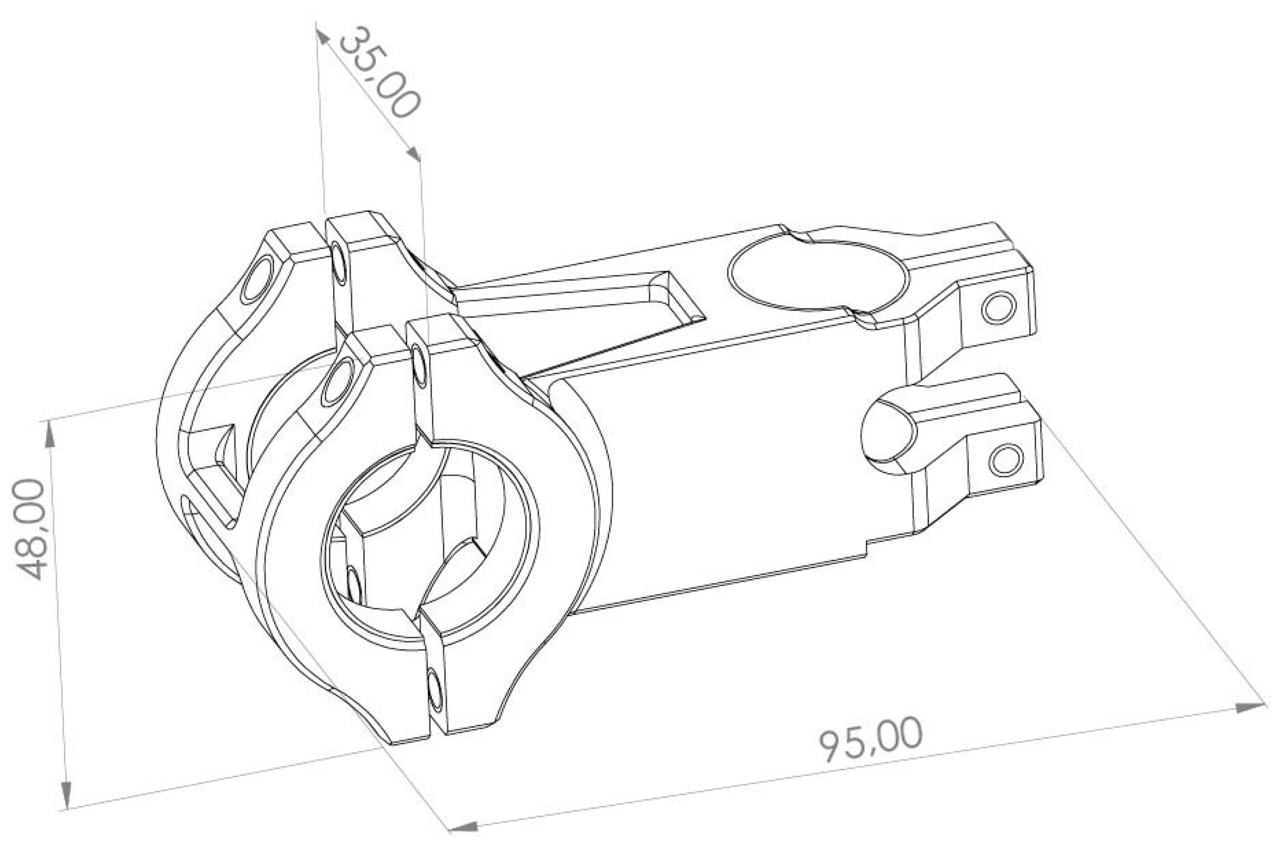
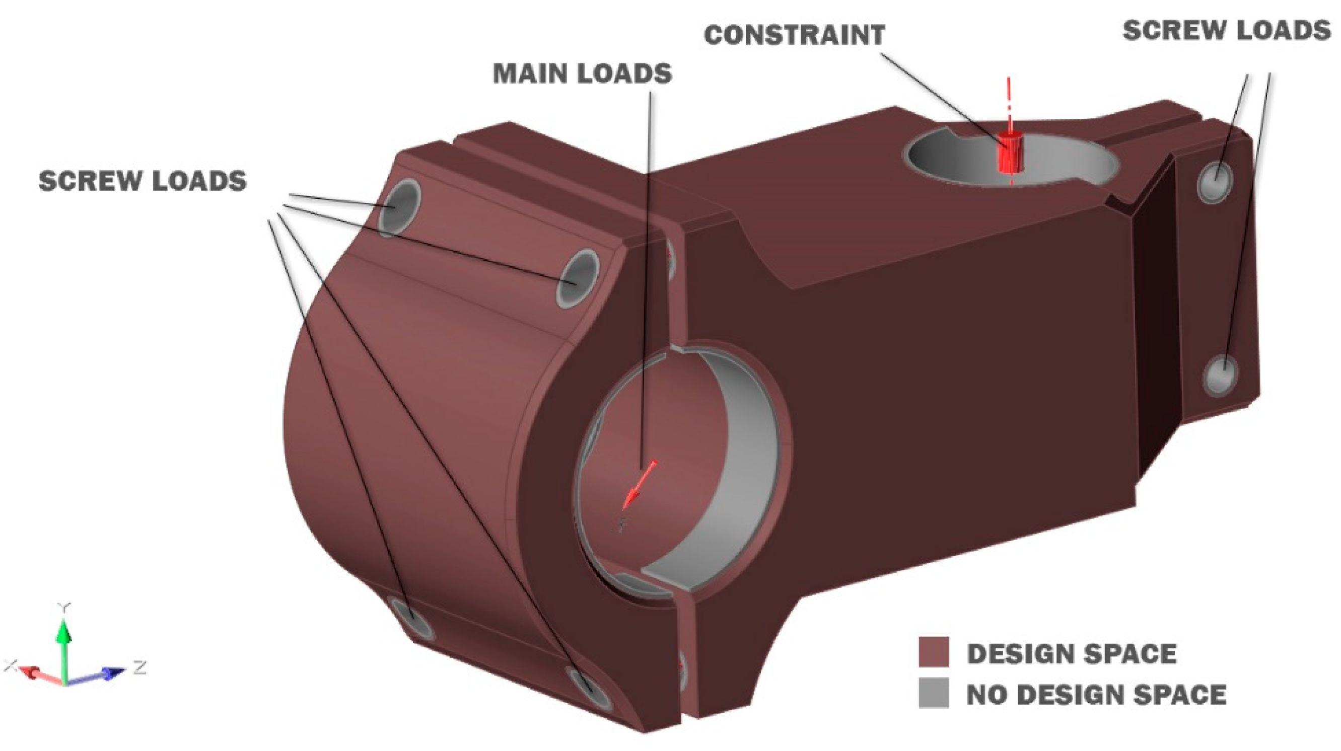
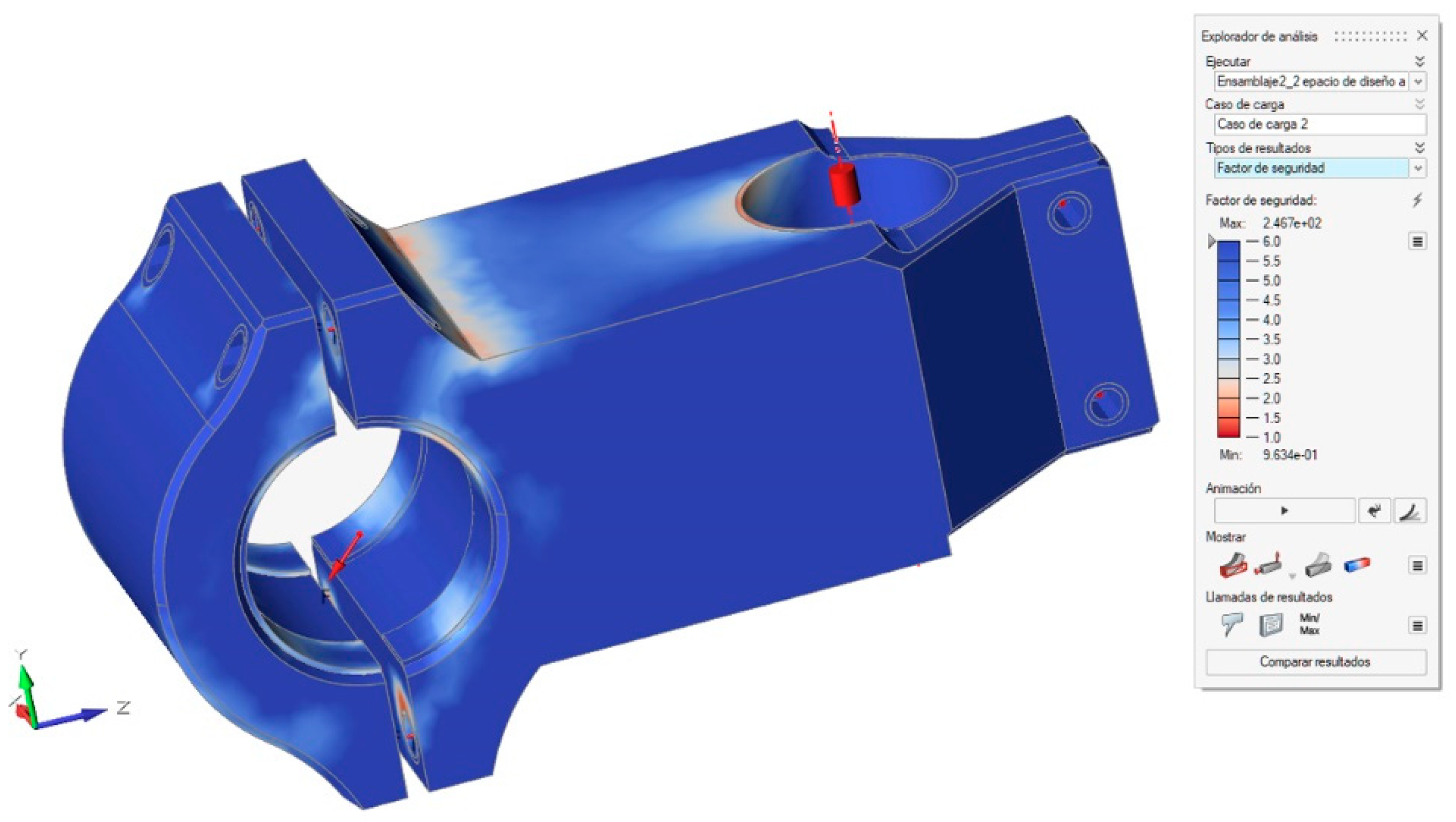
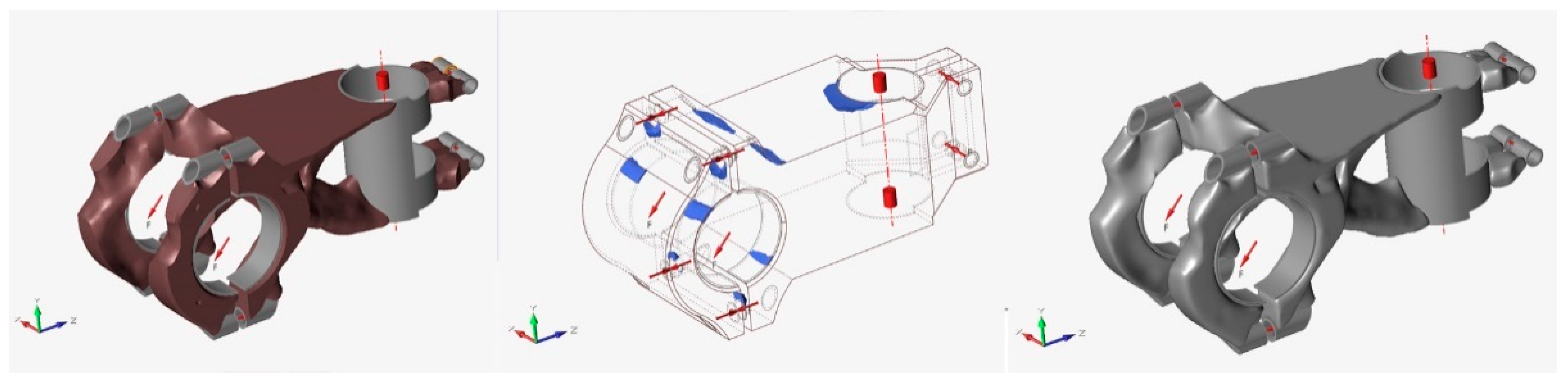
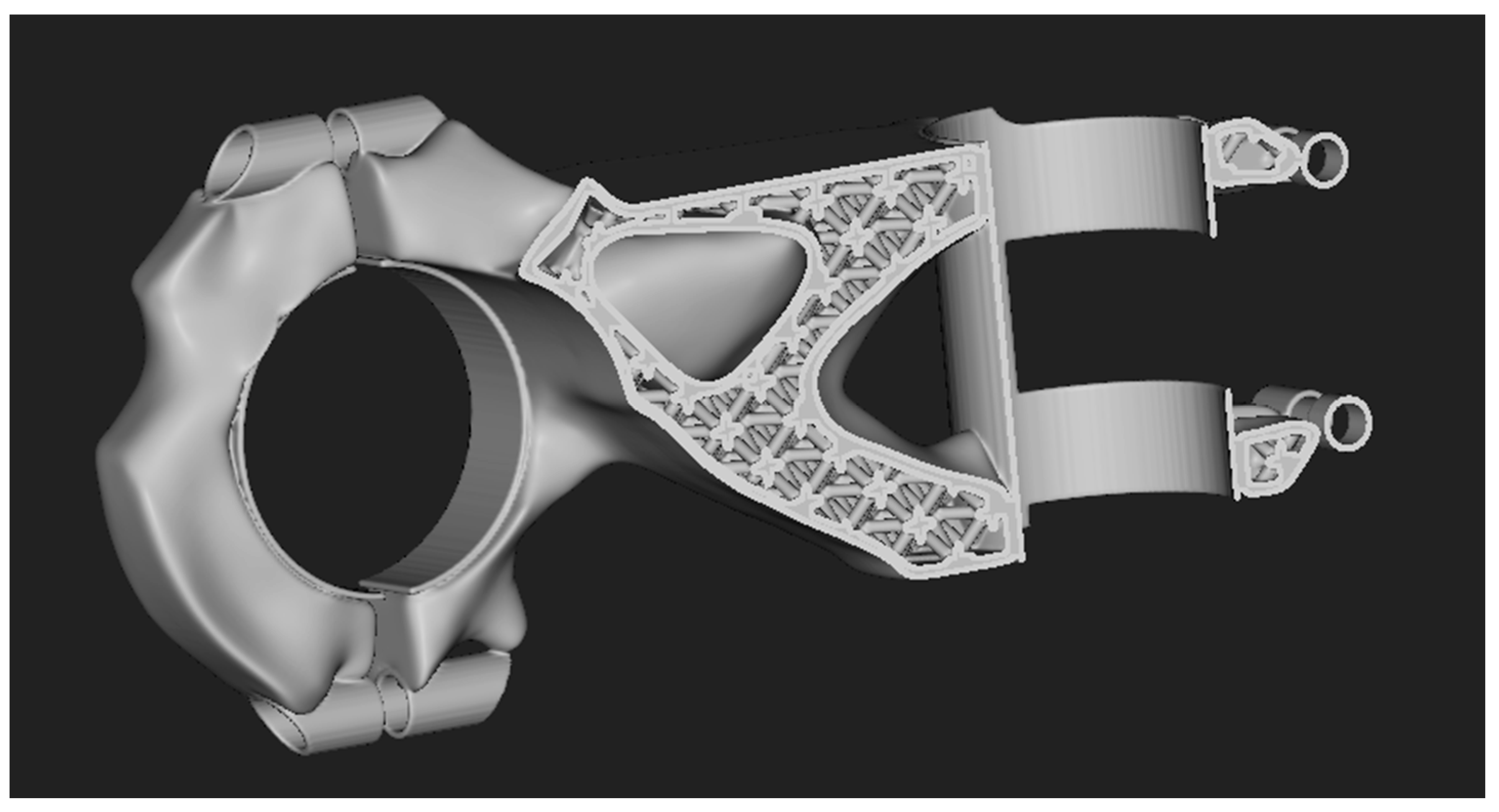
4. Results and Discussion. Case Study: A Bicycle Stem

Next, the case study design of a bicycle stem will be presented. This part is exposed to different loads and is optimized with two different strategies that will create a more efficient design. The part will undergo a topology optimization process and a lattice approach redesign. The goal of both processes is to reduce the part’s weight while preserving the defined mechanical requirements.
There are several publications that show the design process with advanced tools for additive manufacturing. The application of topological optimization in different aeronautical supports [30] or in classical mechanical elements such as beams or hooks is very common [31,32]. Different studies show the possibilities of lattice structures regarding their behavior and mechanical properties. However, there are not many specific applications or study cases that illustrate the use of these tools for specific cases in terms of their procedure of use and execution with the combined use of these design tools [33].
The bicycle stem has maximum dimensions of 95 mm, and is loaded with to two main loads of 1500 N that simulate the weight of the user, increasing up to 3000 N to consider possible jumps or overloads, as shown in Figure 4. The bicycle stem also contains screws that are simulated with a load of 100 N in every hole due to the screw pressure and the pressure direction simulates the tightness of the screws. It also has a restriction of movement in all degrees of freedom due to the connection to the bicycle frame. The material selected for the manufacture and redesign of the part is polyamide 6 or nylon, due to its mechanical strength, hardness, rigidity and good toughness, in addition to a strong mechanical damping capacity and good resistance to fatigue and wear.
The initial design was developed with SolidWorks, a parametric design tool, for the problem specifications. Through simple sketching and basic modeling operations, we can configure the geometry. This will be the starting point for the redesign of the part. The file was exported in STEP format, which allows its import into the Inspire™ tool of Altair™. This topology optimization tool is intuitive and useful for novel users and works with the same calculation engine as the HyperWorks tool from the same company, as well as the OptiStruct software solver. The first action for a TO approach consists of assigning the material from the library to the imported pieces and, as we have mentioned, it will be polyamide 6. It is important to define within the assembly which volumes will be used for optimization and which will not. We will refer to the optimizable volumes where the material removal happens “design spaces” and those that cannot be altered “non-design spaces”, as illustrated in Figure 5. The volume of the design spaces will be increased as much as possible to allow the solver to identify the most suitable solution.
The first step is to perform a static stress calculation according to the defined loads to verify that the part meets the objectives and, above all, that the parts have room for improvement for subsequent redesign. We make a stress simulation and observe the safety coefficient of each of the parts of the piece, as illustrated in Figure 6.
The result clearly expresses that the part is susceptible to optimization since the values of the safety factor greatly exceed a factor of 1.2 that we accept as the admissible limit. Once the need to reduce the mass of this part has been determined, we define a topological optimization that maintains the mentioned safety factor of 1.2, minimizing the mass and maximizing the rigidity of the part. The result will be a poorly defined organic geometry that we will reconstruct using NURBS surfaces that help us to generate a continuous and well-defined surface, as illustrated in Figure 7. This result will also be analyzed by a static calculation to validate the adopted design solution.
With this approach to the redesign of the piece, a notable decrease in weight has been achieved, going from 46.36 g to 24.93 g, which mean a reduction of 53.8% in the optimized piece without losing functionality and according to the design specifications defined at the beginning. Again, this solution is validated by means of finite element analysis (FEA) tools. This solution not only will reduce costs and production times but can also mean important savings in energy consumption with the use of the redesigned part.
This optimized model is intended to take a further step towards weight reduction. Using the lattice tools that have already been mentioned and, more precisely, Ntop software, we intend to further reduce the weight by replacing the continuous material of the part of the piece that can be optimized by generating a microstructure of trusses without losing mechanical properties and maintaining its resistance. It is important to emphasize that the tools used do not allow the validation of the results by means of calculation by finite elements. The simulation strategy should be based on a multiscale homogenization based on the analysis of a representative volume element. Therefore, the result presented below is merely illustrative of the redesign process for mesostructure gratings.
The import/export of files is again done with STEP files. The lattice structure will be applied in the main bodies in a combination of a shell operation and the internal lattices. Ntop software offers a wide range of structures to be applied, which are different in their geometry and are structured by continuous beams or walls, which can be hexagonal, tetrahedral, cubic or random, among others, with different configurations of each of their definitions. In this case, we apply a specific structure, octec, that is an octahedral structure with only eight beams. The result is a 2 mm shell that covers the entire part together with a wired structure infill that will allow, depending on the load requirements, a certain thickness that can also be variable. This allows us to modify the density of the piece by region and even define the position of the center of mass of the part.
The steps followed to obtain the lattice structure, illustrated in Figure 8, are (i) determination of the optimization area, in this case the central body of the bicycle stem. (ii) Definition of the shell thickness and type and size of the structure. (iii) Modification of the wire structure to ensure that there is connection to the parts, and that there are no open structures that reduce their mechanical characteristics. (iv) Definition of the thickness of the cellular structure or lattice, in this case, 1 mm in diameter for each segment. (v) The Boolean union of all the parts that will provide a continuous piece capable of being printed. (vi) Finally, the exportation of the new part in a printable file, such as STL.
The result, as observed in Figure 7, presents a topology-optimized geometry that has reduced weight due to the application of the octec lattice, while maintaining the performance of the product, with lower weight, production time and cost.

5. Conclusions

This article presents an introduction to design for additive manufacturing, illustrating the main advantages and disadvantages of these technologies along with the different stages that make up the process. The main part consists of a review and explanation of the different tools involved in each stage of the process, focusing on additive manufacturing design. In this way, different computer-aided design tools are presented. Some of these tools are well known in the scientific and engineering community, while other, less traditional tools, are new and exclusive for design oriented to additive manufacture. These tools, in their application, will allow us to extract the maximal capacities of these processes, when it is a question of obtaining robust and light design for pieces that need reduced masses. Likewise, this article illustrates the redesign process oriented towards the additive manufacture of a characteristic part of mechanical design: a bicycle stem. In this process, significant improvements in mass reduction are achieved through the application of topological and mesostructural optimization tools, illustrating their use step by step.

Author Contributions

Both authors, D.M.N. and D.M.S. participated in conceptualization, methodology, software, validation, formal analysis, investigation, resources, data curation, writing—original draft preparation, writing—review and editing, visualization, supervision, project administration and funding acquisition. All authors have read and agreed to the published version of the manuscript.

Funding

This research received no external funding.

Institutional Review Board Statement

The study was conducted according to the guidelines of the Declaration of Helsinki, and approved by the Institutional Review Board.

Informed Consent Statement

Informed consent was obtained from all subjects involved in the study.

Data Availability Statement

No new data were created or analyzed in this study. Data sharing is not applicable to this article.

Acknowledgments

The authors would like to acknowledge the support of Junta de Andalucía (INNANOMAT research group, TEP946) and the department of mechanical engineering and industrial design at the Engineering School from Cadiz University.

Conflicts of Interest

The authors declare no conflict of interest.

References

  1. Mueller, B. Additive Manufacturing Technologies – Rapid Prototyping to Direct Digital Manufacturing. In Assembly Automation; Springer: Berlin, Germany, 2012; Volume 32. [Google Scholar]
  2. Niaki, M.K.; Nonino, F. The Management of Additive Manufacturing. Springer International Publishing: Cham, Switzerland, 2018; Volume 93. [Google Scholar]
  3. Gibson, I.; Rosen, D.W.; Stucker, B. Additive Manufacturing Technologies. Springer: New York, NY, USA, 2015. [Google Scholar]
  4. Gardan, J. Additive manufacturing technologies: State of the art and trends. Addit. Manuf. Handb. Prod. Dev. Def. Ind. 2017, 7543, 149–168. [Google Scholar] [CrossRef]
  5. Turner, B.N.; Strong, R.; Gold, S.A. A review of melt extrusion additive manufacturing processes: I. Process. Des. Modeling. Rapid Prototyp. J. 2014, 20, 192–204. [Google Scholar] [CrossRef]
  6. Sossou, G.; Demoly, F.; Montavon, G.; Gomes, S. An additive manufacturing oriented design approach to mechanical assemblies. J. Comput. Des. Eng. 2018, 5, 3–18. [Google Scholar] [CrossRef]
  7. Liou, F.; Newkirk, J.; Fan, Z.; Sparks, T.; Chen, X.; Fletcher, K. Multiscale and Multiphysics Modeling of Additive Manufacturing of Advanced Materials; NASA: Rolla, MO, USA, 2015. [Google Scholar]
  8. Vaezi, M.; Chianrabutra, S.; Mellor, B.; Yang, S. Multiple material additive manufacturing—Part 1: A review: This review paper covers a decade of research on multiple material additive manufacturing technologies which can produce complex geometry parts with different materials. Virtual Phys. Prototyp. 2013, 8, 19–50. [Google Scholar] [CrossRef]
  9. Boyard, N. Design for Additive Manufacturing—DFAM. J. Mater. Process. Technol. 2014, 12, 616–622. [Google Scholar] [CrossRef]
  10. Beyer, C.; Figueroa, D. Design and Analysis of Lattice Structures for Additive Manufacturing. J. Manuf. Sci. Eng. 2016, 138, 121014. [Google Scholar] [CrossRef]
  11. Fernandez-Vicente, M.; Canyada, M.; Conejero, A. Identifying limitations for design for manufacturing with desktop FFF 3D printers. Int. J. Rapid Manuf. 2015, 5, 116–128. [Google Scholar] [CrossRef]
  12. Rodríguez, J.F.; Thomas, J.P.; Renaud, J.E. Mechanical behavior of acrylonitrile butadiene styrene fused deposition materials modeling. Rapid Prototyp. J. 2003, 9, 219–230. [Google Scholar] [CrossRef]
  13. JRodrıguez, F.; Thomas, J.P.; Renaud, J.E. Design of Fused-Deposition ABS Components for Stiffness and Strength. J. Mech. Des. 2003, 125, 545. [Google Scholar] [CrossRef]
  14. Ahn, S.; Montero, M.; Odell, D.; Roundy, S.; Wright, P.K. Anisotropic material properties of fused deposition modeling ABS. Rapid Prototyp. J. 2002, 8, 248–257. [Google Scholar] [CrossRef] [Green Version]
  15. Smyth, C. Functional Design for 3D Printing. Createspace: South Carolina, SC, USA, 2013. [Google Scholar]
  16. Hopkinson, N.; Dicknes, P. Analysis of rapid manufacturing using layer manufacturing processes for production. Proc. Inst. Mech. Eng. Part. C J. Mech. Eng. Sci. 2003, 217, 31–39. [Google Scholar] [CrossRef] [Green Version]
  17. Busachi, A.; Erkoyuncu, J.; Colegrove, P.; Martina, F.; Watts, C.; Drake, R. CIRP Journal of Manufacturing Science and Technology A review of Additive Manufacturing technology and Cost Estimation techniques for the defence sector. CIRP J. Manuf. Sci. Technol. 2017, 19, 1–12. [Google Scholar] [CrossRef] [Green Version]
  18. RedEye, S. Design for Additive Manufacturability: FDM Basics; Stratasys Technical Report; ULTEM: Eden Prairie, MIN, USA, 2014. [Google Scholar]
  19. Steele, K.; Ahrentzen, S. Design Guidelines. Home Autism 2017, 81–170. [Google Scholar] [CrossRef]
  20. London, T. Design for additive manufacturing. Addit. Manuf. Technol. 2015, 17. [Google Scholar] [CrossRef]
  21. Diegel, O.; Nordin, A.; Motte, D. A Practical Guide to Design for Additive Manufacturing; Springer: Singapore, 2019. [Google Scholar]
  22. Ben Redwood, B.G.; Filemon, S. The 3D Printing Handbook: Technologies, Design and Applications; Coers and Roest: Arnhem, The Netherlands, 2017. [Google Scholar]
  23. Interational Organization for Standarization/American Society for Testing Material Additive Manufacturing—General Principles—Terminology; Technical Committee ISO/TC 261 Additive Manufacturing; Vernier: Geneva, Switzerland, 2015.
  24. Aremu, A.; Ashcroft, I.; Hague, R.; Wildman, R.; Tuck, C. Suitability of SIMP and BESO topology optimization algorithms for additive manufacture. In Proceedings of the 21st Annual International Solid Freeform Fabrication Symposium—An Additive Manufacturing Conference, SFF, Austin, TX, USA, 8–10 August 2010; Volume 2010, pp. 679–692. [Google Scholar]
  25. Saeed, N.; Long, K.; Rehman, A. A Review of Structural Optimization Techniques for Wind Turbines. In Proceedings of the 3rd International Conference on Computing, Mathematics and Engineering Technologies (iCoMET), Sukkur, Pakistan, 29–30 January 2020. [Google Scholar] [CrossRef]
  26. Li, C.; Kim, I.Y.; Jeswiet, J. Conceptual and detailed design of an automotive engine cradle by using topology, shape, and size optimization. Struct. Multidiscip. Optim. 2015, 51, 547–564. [Google Scholar] [CrossRef]
  27. Harzheim, L.; Graf, G. A review of optimization of cast parts using topology optimization: III-Topology optimization with manufacturing constraints. Struct. Multidiscip. Optim. 2006, 31, 388–399. [Google Scholar] [CrossRef]
  28. Wang, W.; Munro, D.; Wang, C.C.L.; van Keulen, F.; Wu, J. Space-time topology optimization for additive manufacturing. Struct. Multidiscip. Optim. 2020, 61, 1–18. [Google Scholar] [CrossRef] [Green Version]
  29. Talagani, M.R. Numerical Simulation of Big Area Additive Manufacturing (3D Printing) of a Full Size Car. SAMPE J. 2015, 51, 27–36. [Google Scholar]
  30. Brackett, D.; Ashcroft, I.; Hague, R. Topology optimization for additive manufacturing. In Proceedings of the 21st Annual International Solid Freeform Fabrication Symposium—An Additive Manufacturing Conference, SFF, Austin, TX, USA, 8–10 August 2010; Volume 2010, pp. 348–362. [Google Scholar] [CrossRef]
  31. Liu, J.; Cheng, Z.; Ma, Y. Product design-optimization integration via associative optimization feature modeling. Adv. Eng. Inform. 2016, 30, 713–727. [Google Scholar] [CrossRef]
  32. Rezaie, R.; Badrossamay, M.; Ghaie, A.; Moosavi, H. Topology optimization for fused deposition modeling process. Procedia CIRP 2013, 6, 521–526. [Google Scholar] [CrossRef] [Green Version]
  33. Primo, T.; Calabrese, M.; del Prete, A.; Anglani, A. Additive manufacturing integration with topology optimization methodology for innovative product design. Int. J. Adv. Manuf. Technol. 2017, 93, 467–479. [Google Scholar] [CrossRef]
Figure 1. Additive manufacturing (AM) workflow. Note: CAD (Computer-Assisted Design); CAE (Computer-Aided- Engineering).
Applsci 11 01571 g001
Figure 2. Tools that can be used in the AM process.
Applsci 11 01571 g002
Figure 3. Simple beam parametric optimization (a) of shape (b) and topology (c). Adapted from [1].
Applsci 11 01571 g003
Figure 4. Main dimensions of the bicycle stem designed in the software SolidWorks™.
Applsci 11 01571 g004
Figure 5. Definition of loads and constraints, as well as design and non-design spaces in the Inspire™ tool for the modified stem geometry.
Applsci 11 01571 g005
Figure 6. Result of the finite elements analysis expressed as safety factors of the part using the Inspire™ tool.
Applsci 11 01571 g006
Figure 7. Result of the topological optimization on the left, the middle image shows the highest stress concentration areas and, on the right, the smoothed surface using NURBS, carried out with Inspire software.
Applsci 11 01571 g007
Figure 8. Section view of the result of the redesign using lattice-type tools with Ntop platform software.
Applsci 11 01571 g008
Table 1. List of remarkable software used in additive manufacturing design processes.
SchemeOriented to AMMain Functions Related to AMEase of UseCost *
SolidWorks/Inventor/PTC Creo/Not specifically but usefulSolid and surface parametric modeling and basic FEAEasyMedium
NX/Fusion360YesSolid and surface modeling/Basic simulationEasyLow/Free student version
Free CADNot specifically but usefulSolid and surface modelingMediumFree
CatiaYesSolid and surface modelingEasyHigh
Rhinoceros 3DNot specifically but usefulSurface and freeform modelingEasyLow
BlenderNot specifically but usefulOrganic modeling and animationMediumFree
3D MaxNot specifically but usefulOrganic modeling and animationMediumMedium/Free student version
InspireYesOptimization/Lattice/Simulation/Printing setupEasyMedium/Free student version
Abaqus, HyperWorks, AnsysNot specifically but usefulSimulations and TOComplexHigh
NtopYesBasic modeling/Lattice/TO/Simulation/Printing setupComplexMedium/Free student version
3D MaticYesModeling/Lattice/Mesh editor/Topology optimizationMediumMedium
NetfabbYesLattice/Mesh editorMediumHigh
ParetoYesTOLowMedium
ToscaYesTO and printing setupMediumHigh
ParamattersYesTOLowLow
Digimat AMYesProcess simulation (polymers)LowMedium
SimufactYesProcess simulation (metals)HighHigh
AlphastarYesFEA/Process simulationMediumHigh
Cura/Prusa SlicerYesProcess condition definition and G-code generationLowFree
Simplify3DYesProcess condition definition and G-code generationMediumLow
MeshmixerYesMesh editionLowFree
MagicsYesMesh edition, process conditions definition and G-code generationLowHigh
* Cost is an estimation from the academic environment based on a comparative analysis. Suppliers give specific quotations depending on final use. They can change depending on whether the client belongs to industry, academia or a research center. Note: TO (Topological Optimization).
Publisher’s Note: MDPI stays neutral with regard to jurisdictional claims in published maps and institutional affiliations.

