1. Introduction
With the rapidly increasing urban power load, the security of coastal urban power (CUP) supply is facing challenges [
1] because of the shortage of transmission corridors and limitation of short circuit capacity [
2,
3]. Meanwhile, the CUP grid security has further deteriorated as a result of the large scale integration of offshore wind power [
4,
5]. High voltage direct current based on voltage source converter (VSC-HVDC) technology is recognized as an advanced approach for efficient and stable operation in future CUP grid [
2], due to their high transmission capability [
6,
7], the flexibility of power dispatch and no short circuit current limitation et al. [
2,
8].
Up to now, several point-to-point VSC-HVDC projects [
2,
3,
9] have been in operation or planned for the CUP grid. With the enlargement of the CUP grid, more than one point-to-point VSC-HVDC systems in different areas will be put into operation in the same CUP grid. To improve system flexibility and reliability, VSC-HVDC systems can be interconnected and developed into a coastal urban multi-terminal DC (CU-MTDC) system.
When MTDC is applied in the CUP grid, the main control objective is to relieve the transmission stress of the critical AC lines and improve the power supply security. Meanwhile, to realize the local absorption, offshore wind power further affects the security of the power supply to the CUP grid. Therefore, taking the power supply security into account, coordinated control strategies of the CU-MTDC are very important.
In recent years, as a new research field, some researchers have begun to pay attention to the application of VSC-HVDC in the urban power grid. In [
10], the authors proposed a locating and sizing method of interconnected converter stations. According to the method, the optimum location and capacity of the converter station are well determined. However, the control strategy of the DC system is not involved. On the basis of the [
10], the detailed control strategy of a back-to-back VSC-HVDC interconnected two load areas of the urban power grid is proposed in [
11]. In this paper, the proposed method includes load-balanced control, emergency support control and static voltage control. The results verify the effectiveness of the proposed control strategy. In [
12], a coordinative control model that combines the load transfer capability of the HVDN and flexible and precise control of VSC is proposed to alleviate the urban transmission congestion. Although the above two papers have studied the control of VSC-HVDC in the urban power grid, the research project is the two-terminal DC system, and the multi-terminal DC system is not mentioned. Reference [
13] focuses on a multi-voltage urban DC system and proposes a comprehensive control strategy that included free operation mode, limit operation mode and layer operation mode. Based on [
13], a coordinated operation strategy for DC grids applied to the multi-regional urban power grid is studied in reference [
14], and the coordination between multiple DC subsystems is analyzed. However, the influence of the AC system is not considered in the proposed coordinated control strategy, especially the power supply security. Based on the above analysis, the research on urban MTDC needs further attention.
Compared with the research on urban MTDC, considering the influence of the AC system, the coordinated operation mode and control strategy of MTDC in large power systems have been extensively studied, which can be used for reference. In [
15], the paper considers the OPF of a meshed AC/DC system with MTDC networks. The OPF problem is formulated to minimize the transmission loss of the whole AC/DC network. In [
16], an extended OPF model with a detailed MTDC is proposed. And then, a cost–benefit analysis approach using the model is proposed to determine the economy of the VSC project. In [
17], the paper focuses on the frequency security of the AC system after DC fault and proposes a distribution method of DC unbalanced power. The simulation results show the method can effectively reduce the frequency fluctuation. The above research optimized the operation mode of MTDC through different control objectives. However, the power supply security of the AC system has not been given special attention and is usually introduced into the optimization process only as an inequality constraint. Therefore, considering the power supply security, a better-optimized operation mode of MTDC is obtained by the security-constrained optimal power flow (SCOPF) method. In [
18], improved corrective security-constrained OPF for a meshed AC/DC power grid is proposed. The security constraints of N−1 contingencies for both AC and DC networks are fully considered. The results show that this method can be applied to middle and long-term schedules. In [
19], a hierarchical SCOPF model is proposed for an AC/DC system. The MTDC system could provide support for the AC system by redistributing power flow across the entire grid. Through the above methods, the power supply security of the AC/DC system is fully considered. However, due to the large-scale power grid and too many optimization factors, this kind of method cannot be applied in real-time control because of the complicated calculation process. Therefore, a more direct calculation method is proposed for real-time control in [
20]. In this paper, active power sensitivity is used to calculate the redistribution of DC unbalanced power after DC fault. The methods can guarantee power supply security by distributing the DC unbalanced power among all the normal converters. However, the influence area of DC fault on the AC system is expanded. In addition, the detailed coordinated control strategy is not proposed to cooperate with the calculation method, and parameter design of controllers is not involved.
In general, the drawbacks of the existing approaches are described as follows:
- (1)
The DC unbalanced power distribution method usually adopts an optimized calculation method using global data. There are generally many optimization factors in this kind of calculation method, and the calculation process is very complicated. Therefore, it is difficult to apply the existing approaches to real-time control;
- (2)
The DC unbalanced power distribution strategies usually adopt all the normal converters to participate in the regulation, which inevitably leads to the expansion of the influence range of a DC fault on the AC system.
To solve the problems in the exiting approaches, a novel coordinated control strategy of CU-MTDC under abnormal conditions is proposed in this paper. Compared with traditional methods, the proposed method offers the following features and improvements:
- (1)
Based on the priority control idea, the control thresholds of different priorities are determined by the magnitude of the DC unbalanced power value and the maximum regulation capacity of the converter. The calculation and control process is very simple, which is easy to realize real-time control;
- (2)
The number of the regulation converters is dynamically scheduled according to the DC unbalanced power value, instead of all the converters involved in control. With the proposed method, the influence range of DC faults on the urban power grid can be limited in a sufficiently small area;
- (3)
Moreover, the parameter design of controllers is proposed to cooperate with the distribution strategy, which is very friendly to practical engineering realization.
The rest of this paper is organized as follows:
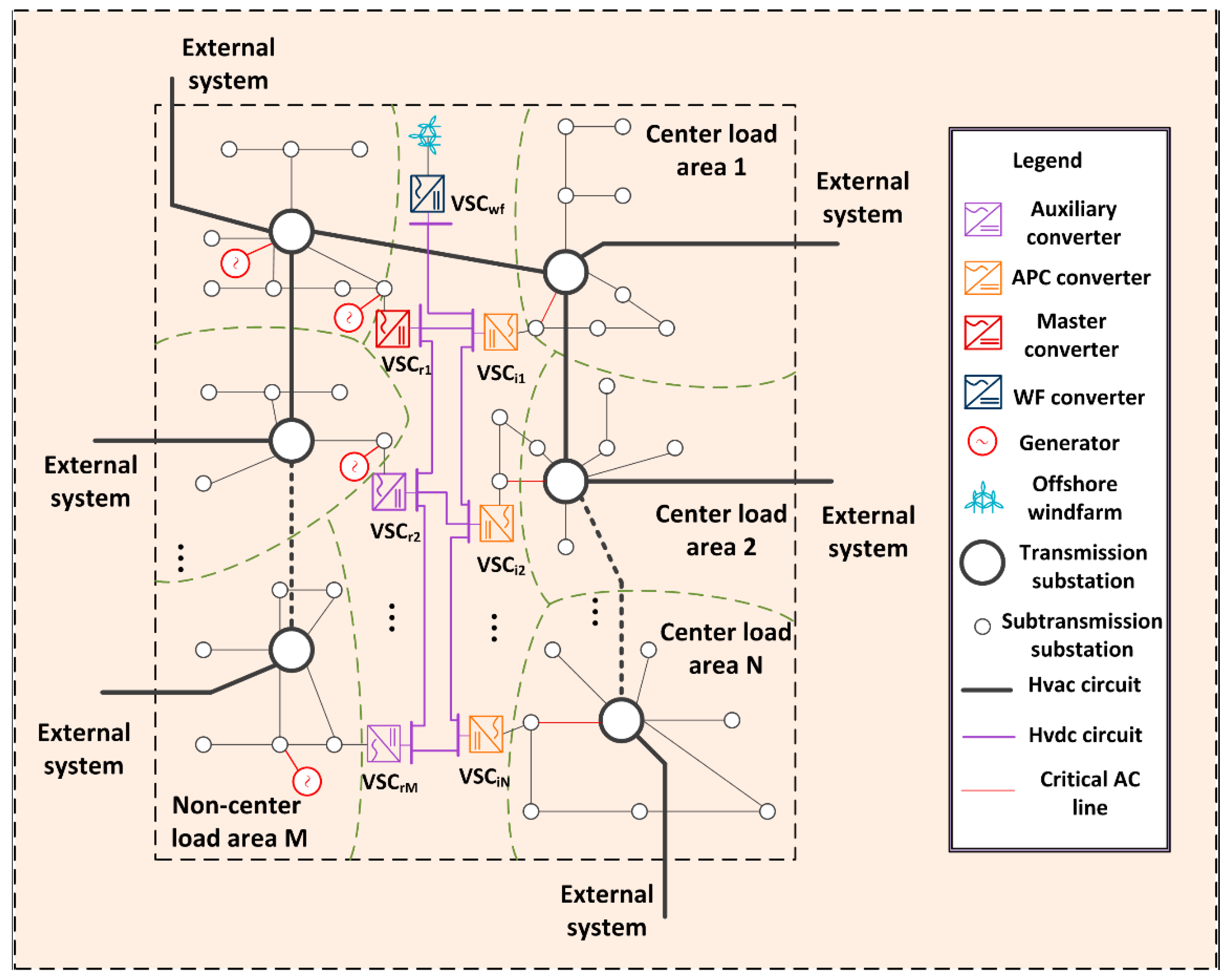
Section 2 describes the basic system structure of CU-MTDC. In
Section 3, the coordinated control strategy of CU-MTDC under abnormal conditions is proposed. The results of the simulations are performed in
Section 4. Finally,
Section 5 concludes the paper.
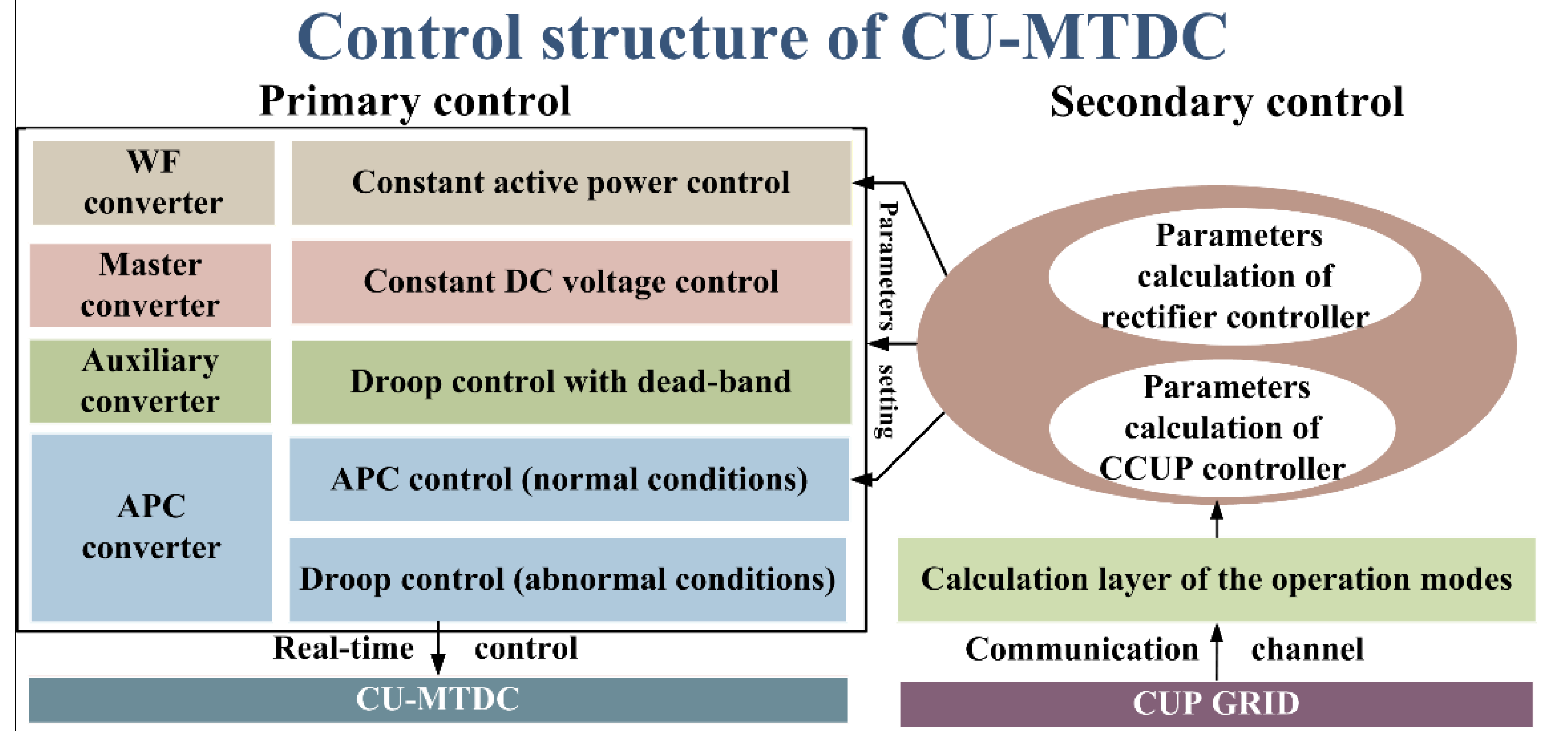
3. Proposed Coordinated Control Strategy of CU-MTDC under Abnormal Conditions
3.1. Basic Concept
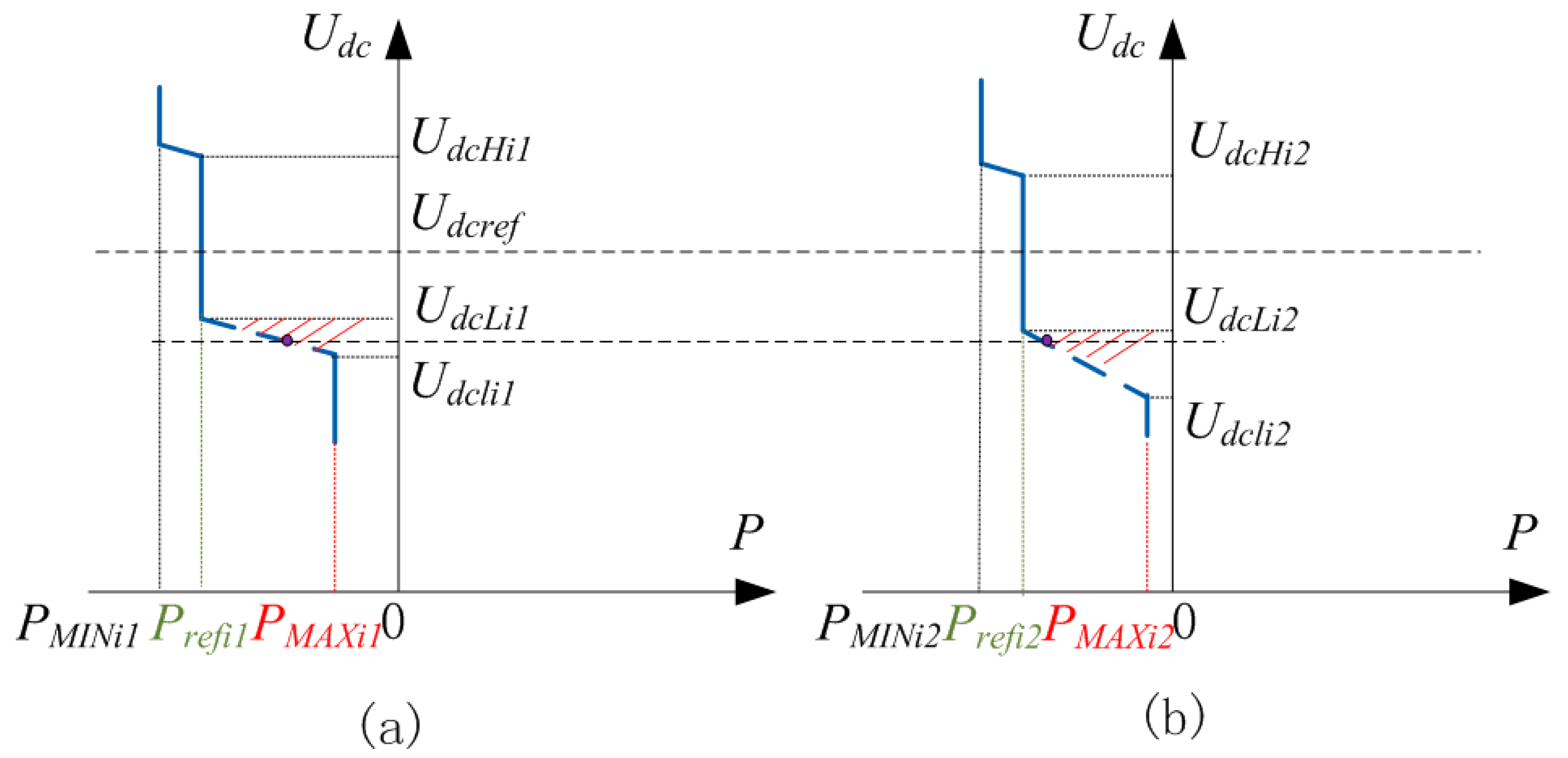
As shown in
Figure 1 and
Figure 3, if DC unbalanced power exceeds the regulation capacity of the master converter and auxiliary converter, DC voltage will be out of control until the APC converters change into droop control. Therefore, the active power of the APC converter reduces rapidly, and the load ratio of the interconnected critical line increases. As a result, the coordinated power redistribution strategy is required to guarantee power supply security.
In the traditional method, all the normal converters are involved in power distribution. Total regulation capacity is fully utilized, and the security of all the critical AC lines is confirmed. However, the DC power variation impacts the power flow among all areas of the AC system. Meanwhile, the constant active power supply of the APC converter is broken, and some unnecessary costs occur, considering the requirement of the electricity market. As a result, dynamically scheduling the number of the regulation converter according to the value of DC unbalanced power is a feasible solution method when the unbalanced power is less than a certain value. Generally, there exist two basic scenarios of unbalanced power coordinated distribution under abnormal conditions.
Scenario 1: The first scenario is that the DC unbalanced power is absorbed by one or more converters, which is referred to as the priority control mode.
Scenario 2: The second scenario is that the DC unbalanced power will be absorbed by all the normal APC converters, which is referred to as the shared control mode. Under this condition, the active power output value of every regulation converter should be further confirmed by a specific objective. In this paper, the control objective is all the critical AC lines that are interconnected with the APC converters have the same load ratio.
It should be noticed that offshore wind power directly affects DC unbalanced power. Therefore, the influence of offshore wind power on control can be generalized into the effect of the unbalanced power.
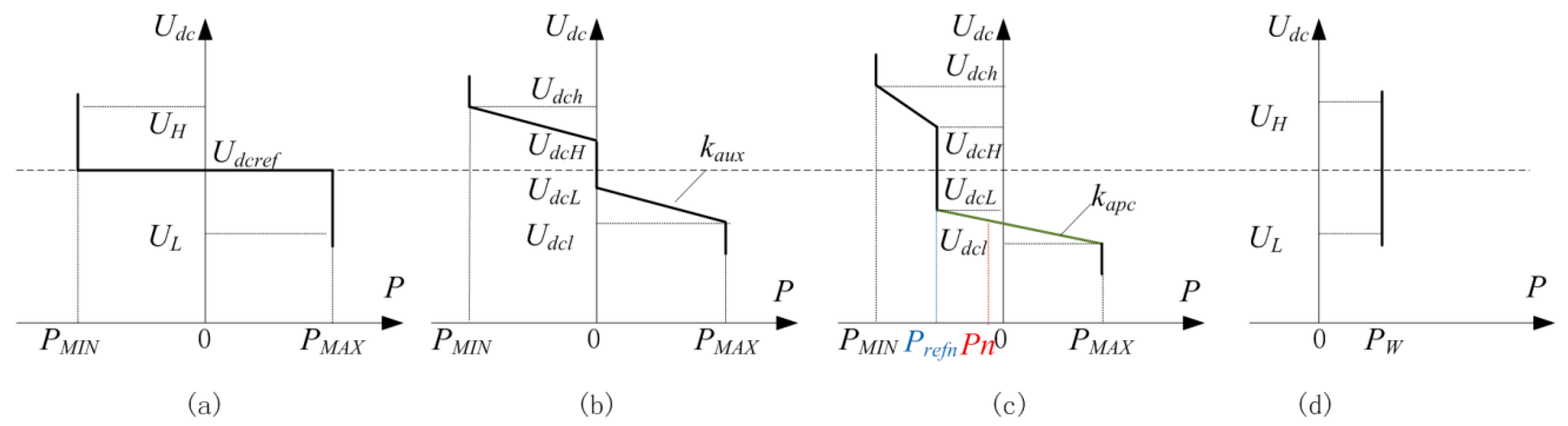
As shown in
Figure 3c, two active power values of the APC converter are very important for the objective control implementation. The active power reference value
Prefn and the actual active power output value
Pn are calculated according to the proposed method, which is described in
Section 3.2 and
Section 3.3.
3.2. Calculation of Active Power Reference Value
In this section, calculation principles for active power reference value are described as follows:
- (1)
The reference value should ensure the N-1 security criterion under normal conditions, which is
where
Prefn is the active power reference value of converter station
n.
PrefnLi,j is the active power reference value of the
n station to ensure the N-1 security after the AC line
Li,j outage.
Considering the requirement of security operation of the power grid, the security margin of
PrefnLi,j should be reserved.
where
ε is the security margin of the transmission line.
SLi,j is the maximum capacity of the
Li,j.
According to (1) and (2), the CU-MTDC provides enough power supply security support to the AC system.
- (2)
Taking offshore wind power into account, the reference value should ensure the wind power is locally absorbed.
Assuming N converters are interconnected with the CCUP grid. The maximum offshore wind power absorption can be expressed as
where
Pw is the active power of wind farms.
According to (1), (2) and (3), the active power reference value can be confirmed.
3.3. Unbalanced Power Coordinated Distribution Strategy Considering Power Supply Security
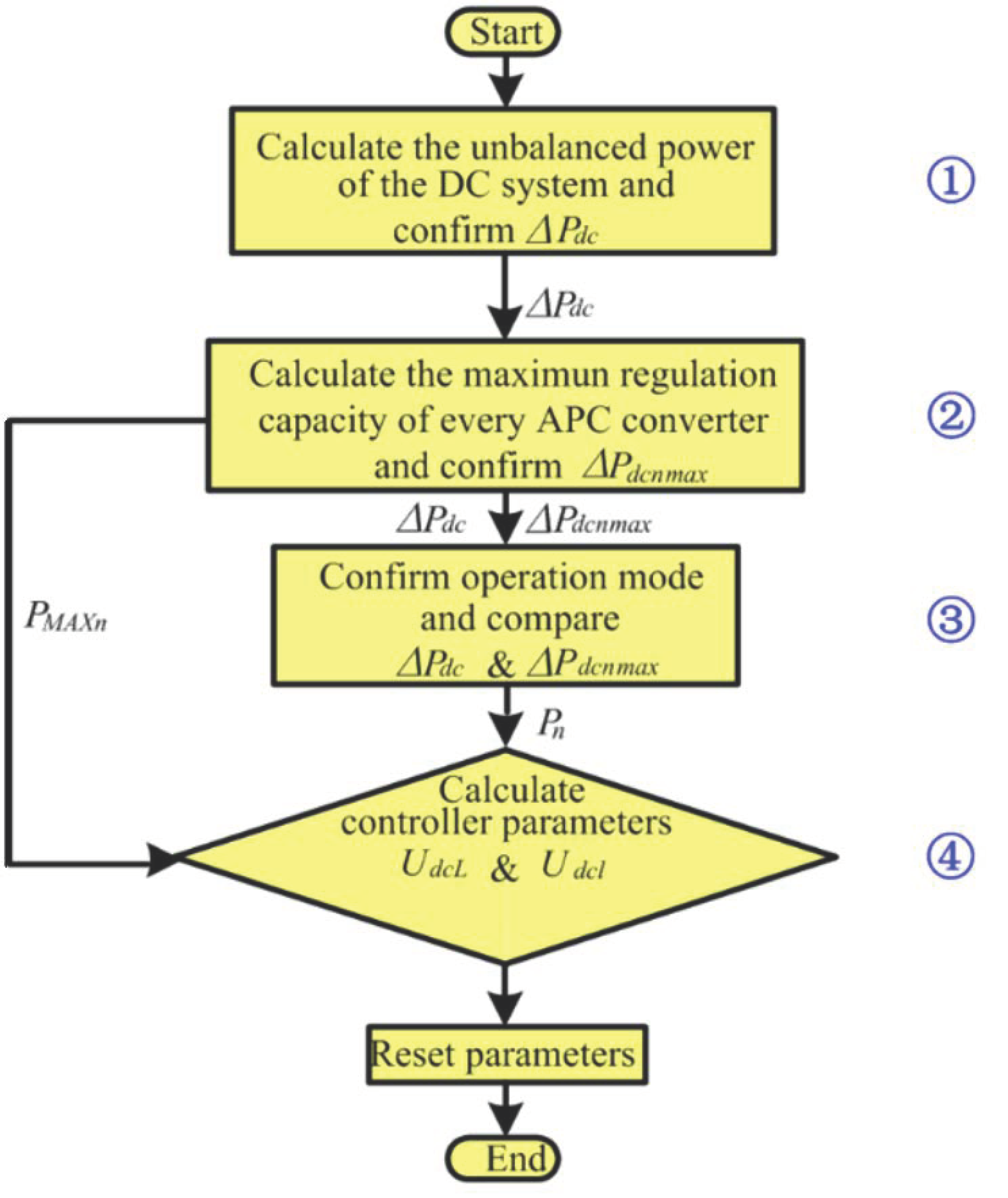
When the system DC voltage is out of control, the proposed unbalanced power coordinated distribution strategy will start immediately. The detailed implementation procedure can be divided into three steps, as follows:
Step 1: Calculate the unbalanced power of the DC system
Assuming M converters operate under rectifier mode, and then the DC unbalanced power can be calculated:
where Δ
Pdc and Δ
Pm are the DC unbalanced power and active power variation of rectifier converter
m, respectively.
Step 2: Calculate the maximum regulation capacity of every APC converter
According to the power flow calculation method, the maximum allowable value of the APC converter active power can be written as:
where
Prefnmax is the maximum active power reference value of the APC converter
n when the active power of interconnected critical line will not exceed the limit value.
The maximum regulation capacity of converter
n can be expressed as:
Step 3: Compare ΔPdc with ΔPdcnmax and confirm operation mode
After comparing Δ
Pdc with Δ
Pdcnmax, the operation modes of the APC converters are confirmed based on the proposed two scenarios. Because two converters participating in the DC unbalanced power regulation is the most basic and common operation mode in the system, this mode is studied first in this paper. To facilitate analysis, VSC
i1 and VSC
i2 of CU-MTDC, which are shown in
Figure 1, are set to control DC voltage after the DC unbalanced power exceeds the system regulation capacity of the master converter and auxiliary converter.
- (1)
Priority control mode: As shown in
Figure 1, the control mode can be further divided into VSC
i1 priority mode and VSC
i2 priority mode. Because the two modes have a similar calculation procedure, only the VSC
i1 priority mode is introduced in detail and is shown in
Figure 4.
Assuming ΔPdci1max > ΔPdci2max, the judgment process is introduced as follows:
Under this condition, VSCi1 turns into droop control, and VSCi2 keeps the initial operation mode.
If (Δ
Pdci2max < Δ
Pdc < Δ
Pdci1max), the DC unbalanced power will be absorbed by VSC
i1, which is:
where
ki1 is the droop coefficient of VSC
i1:
It should be noticed that a backup droop control is applied in VSCi2. The main responsibility of this design is to avoid DC voltage out of control in case of some accidents occur, such as information loss or wind power fluctuation. In addition, the shadow area is represented as the range of droop coefficient and can be confirmed with the requirement of the control effect. Moreover, the control margin, which is reserved for VSCi2, should also be considered.
If (ΔPdc < ΔPdci2max), VSCi2 will operate on a similar mode, and the distribution result can refer to the analysis above.
- (2)
Shared control mode: As shown in
Figure 5, under this condition, VSC
i1 and VSC
i2 jointly realize the unbalanced power distribution.
If (Δ
Pdci1max < Δ
Pdc < Δ
Pdci1max + Δ
Pdci2max), the DC unbalanced power will be distributed as follows:
where
ki2 is the droop coefficient of VSC
i2:
To realize the accurate distribution of VSC
i1 and VSC
i2, the load ratio of the critical line is defined as:
With the proposal of equivalent load ratio of critical lines, that is,
βLi,j =
βLg,k,
Pi1 and
Pi2 can be calculated specifically:
where Δ
Pdcloss is the variation of DC power loss before and after power distribution.
According to (12) and (13), the DC unbalanced power can be accurately distributed by both VSCi1 and VSCi2.
If (ΔPdc > ΔPdci1max + ΔPdci2max), a special condition of the shared control mode occurs. Under this condition, the supply security of one critical line should be broken to ensure the stable operation of the DC system. The APC converter, which is interconnected with a strong area, will continue absorbing unbalanced power, and the other one outputs the maximum power allowed by power supply security. At this time, the rated active power capacity of the APC converter connected with the strong area is set to the reserve regulation capacity to maintain the stable DC voltage of the system.
3.4. Unbalanced Power Coordinated Distribution Strategy When the Number of the APC Converter Exceeds Two
When the number of the APC converter, which is set to control DC voltage, exceeds two, the operation mode can be regarded as a combination of the two basic modes and has a similar analysis process.
Taking the number of the APC converter is three as an example, assuming Δ
Pdci1max < Δ
Pdci2max < Δ
Pdci3max, the detailed coordinated distribution strategy is described as follows in
Table 1.
As shown in
Table 1, it is observed that the coordinated control strategy becomes more complex with the increasing number of the APC converter. It limits the proposed control strategy applied to a very large system. However, in the urban power grid, very many APC converters participating in system regulation is not needed. Thus, the proposed control strategy is appropriate and could be applied to the coastal urban power system with the VSC-MTDC system.
3.5. Calculation of the APC Converter Controller Parameters
Take the CU-MTDC, which is shown in
Figure 1 as an example; the detailed calculation procedure of the APC converter controller parameters is described. Meanwhile, the master converter outage is used as an application scenario to guarantee the security operation of the DC system under the most serious abnormal condition. The DC gird equation can be written as:
where [U]
n − 1 × n − 1 =
diag[
Udc2, Udc3, Udc4,…Udcn − 1] is a diagonal matrix comprised of DC bus voltage.
As shown in
Figure 4 and
Figure 5, when the VSC
i1 and VSC
i2 are set to control DC voltage, two parameters
UdcL and
Udcl are very important for control objective implementation. The detailed calculation procedure is described as follows:
- (1)
The calculation of Udcl. UdcL is the starting voltage of the droop control and should be determined by the minimum DC voltage of the APC converter under normal conditions. In this paper, UdcL should be calculated when the power of the wind farm is zero and APC converters output maximum power.
Under shared control mode, the
UdcL of VSC
i1 and VSC
i2 can be obtained by DC power flow calculation, and a DC voltage security margin should be reserved, which is:
where
U*dcL is the DC voltage got from the power flow calculation,
Udcε is the DC voltage security margin.
Under priority control mode, such as VSCi1 priority mode, the UdcL of VSCi1 can be determined according to (15). The UdcL of VSCi2 should be confirmed along with Udcl of VSCi1.
- (2)
The calculation of Udcl. Udcl is the cut-out DC voltage of the droop control. Under shared control mode, Udcl of the two converters, which are set to control DC voltage, determines the DC unbalanced power distribution directly.
Substitute (10) and (12) into (9), the characteristics of the APC converter can be expressed as:
According to (12), (13), (14) and (16), the controller parameters can be calculated.
Based on the above-mentioned, under VSCi1 priority mode, the selection of Udcli1 should consider the control margin, which is reserved for VSCi2. To ensure control security, the control margin should refer to the practical requirements and not be set too small. In this paper, 3% of the rated DC voltage should be set as the security margin for DC voltage control of VSCi2.
The flowchart of complete operation mode confirmation and controller parameters calculation can be shown in
Figure 6.
4. Case Study
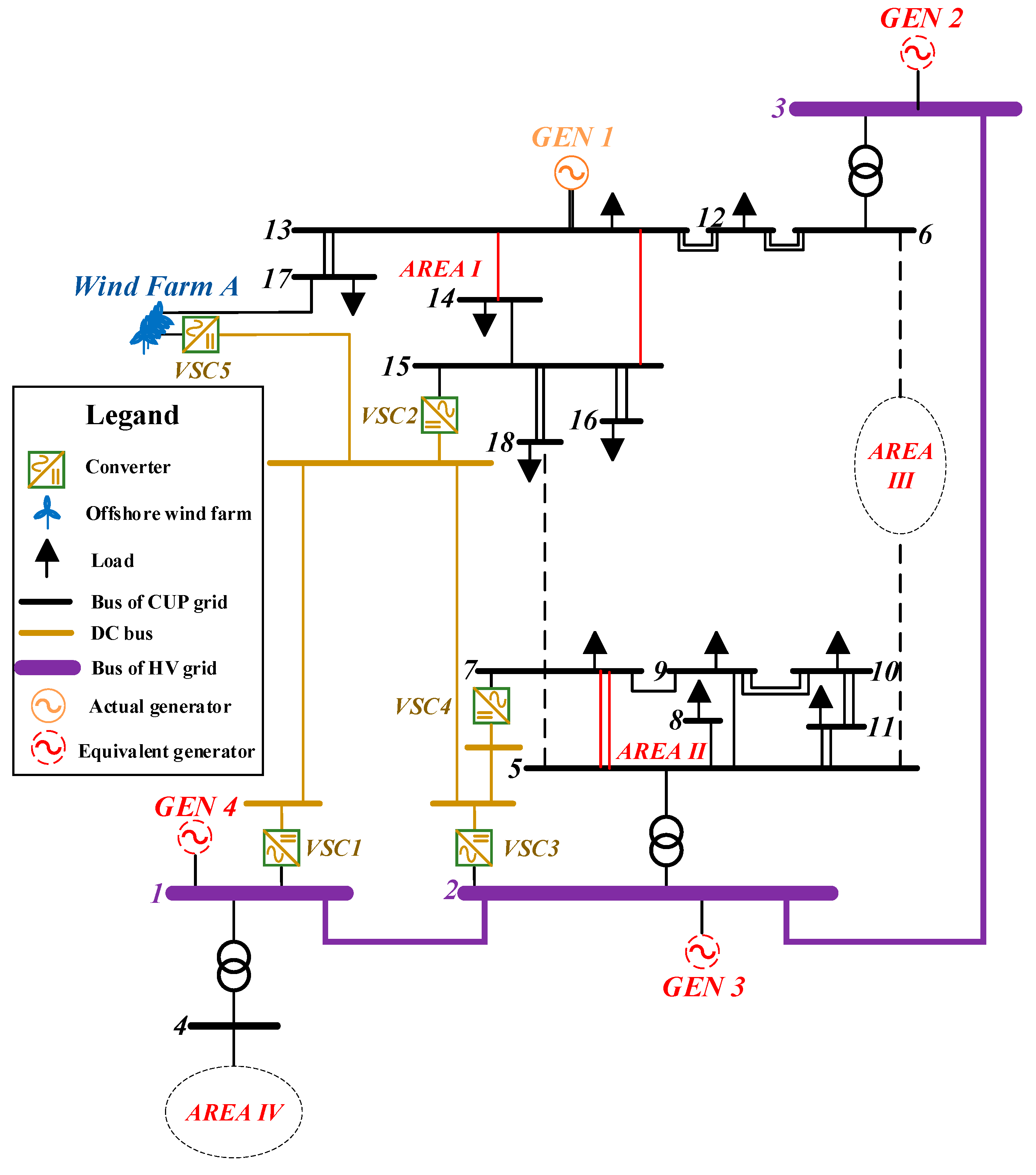
In this section, the five-terminal CU-MTDC and interconnected CUP grid shown in
Figure 7 are studied in PSCAD/EMTDC to verify the feasibility of the proposed coordinated control strategy under abnormal conditions. An actual CUP grid topology in the eastern coast of China and the data of maximum operation mode in summer [
23] are applied in the simulations. Three critical lines
L5–7,
L13–15,
L13–14, are facing transmission stress problems (load ratio exceeds 90%). However, additional AC lines are not allowed because of the shortage of transmission corridors and the limitation of short circuit capacity. The short-circuit current of
Bus13 and
Bus2 is close to the maximum breaking current of a break. Moreover, offshore wind farm A is interconnected with the CUP grid via the HVAC. The random and intermittent characteristics of the wind power will further increase the transmission stress of the critical lines, even lead to serious security problems. Based on the analysis above, a five-terminal CU-MTDC is finally applied in the CUP grid.
VSC
1 and VSC
3 are directly connected with a high voltage (HV) grid and generally operate on rectifier mode. VSC
2 and VSC
4 interconnect with the CCUP grid and operate on inverter mode. VSC
1 is the master converter station to keep constant DC voltage control under normal conditions. VSC
3 is the auxiliary converter station to assist the DC voltage control. VSC
2 and VSC
4 are APC stations. The APC converter should turn into droop control under abnormal conditions. VSC
5 is an offshore wind farm converter. The active power capacity of converter 1 and 2 are all rated 500 MVA. The rated active power of converter 3, 4 and 5 are 250 MVA, 200 MVA and 400 MWA, respectively. The length of DC cable between terminals are
L12 =
L23 =
L25 = 40 km,
L34 = 20 km. The detailed parameters of the DC/AC system are shown in
Table 2,
Table 3 and
Table 4. The diagram of the whole system is shown in
Figure 8.
From
Table 3, the load ratio of
L13–15 and
L13–14 are lower than 90%. However, the power flow of the two transmission lines cannot be control independently. To prevent one of the two transmission lines from exceeding the limit value, a limit security value of the two lines’ power sum is set at 700 MW by the operation department of the power grid. The security margin of the AC lines power limit value ε is set as 5%. Considering the value of ε, the limit value of the critical lines are 243 MW and 665 MW, respectively.
As shown in
Figure 7, the CUP grid can be divided into four areas. To reduce the complexity of the description,
Figure 8 is shown as a simplified topology. Only some important regions of areas I and II are shown in detail.
The DC voltage reference value of the CU-MTDC is selected at 400 kV. The maximum security of the DC voltage range of all the converters is ±10%, and Udcε is set as ±1%. According to (1), (2) and (3), the initial active power reference value of VSC2 and VSC4 are 500 MW and 200 MW.
In the coastal urban power grid, different load conditions will directly affect the maximum regulation capacity of the APC converter according to the proposed method. In this paper,
load18 and
load7 are selected to simulate different load conditions by changing the active power. The influence of the load variation on the maximum regulation capacity of the converter is shown in
Table 5.
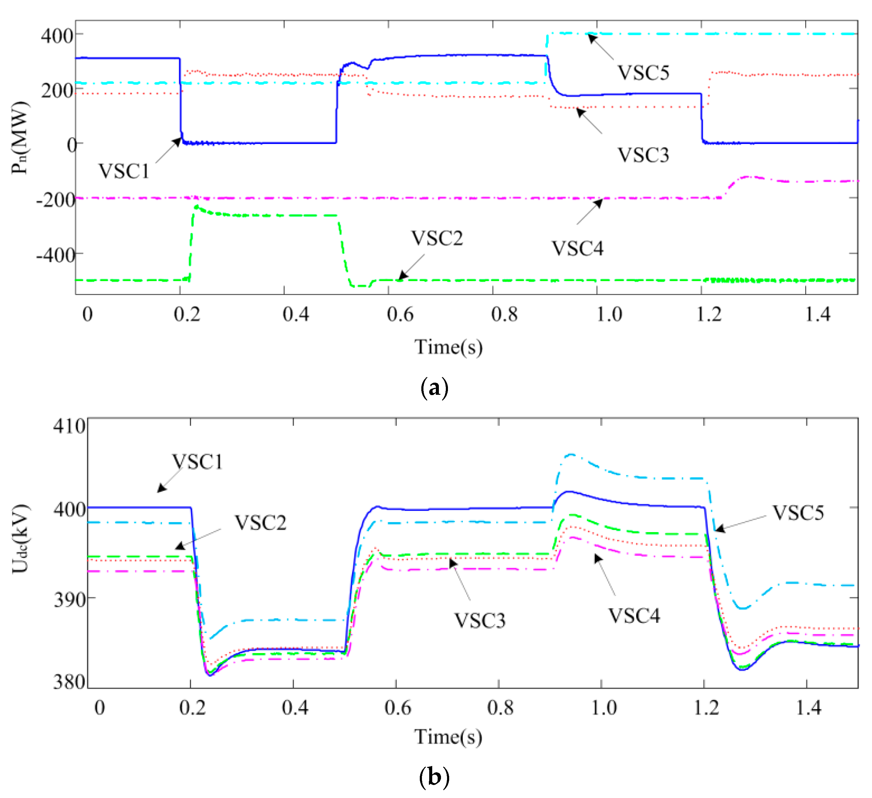
4.1. Simulation under Priority Control Mode
In this case, the load condition is selected No.6 in
Table 5. The active power of the
Load18 and
Load7 are increased by 100 MW and 50 MW, respectively. The maximum regulation capacity of the APC converters are Δ
Pdc2max = 370 MW and Δ
Pdc4max = 150 MW under this condition. The initial active power of converter 2, 4 and 5 are 500 MW, 200 MW and 220 MW. When
t = 0.2 s, a temporary inner fault occurs in master converter 1 and lasts for 0.3 s, which results in the converter 1 blocking. At
t = 0.9 s, the active power of the offshore wind farm increases to 400 MW. When
t = 1.2 s, converter 1 is out of operation because of a serious converter fault. The simulation results are shown in
Figure 9.
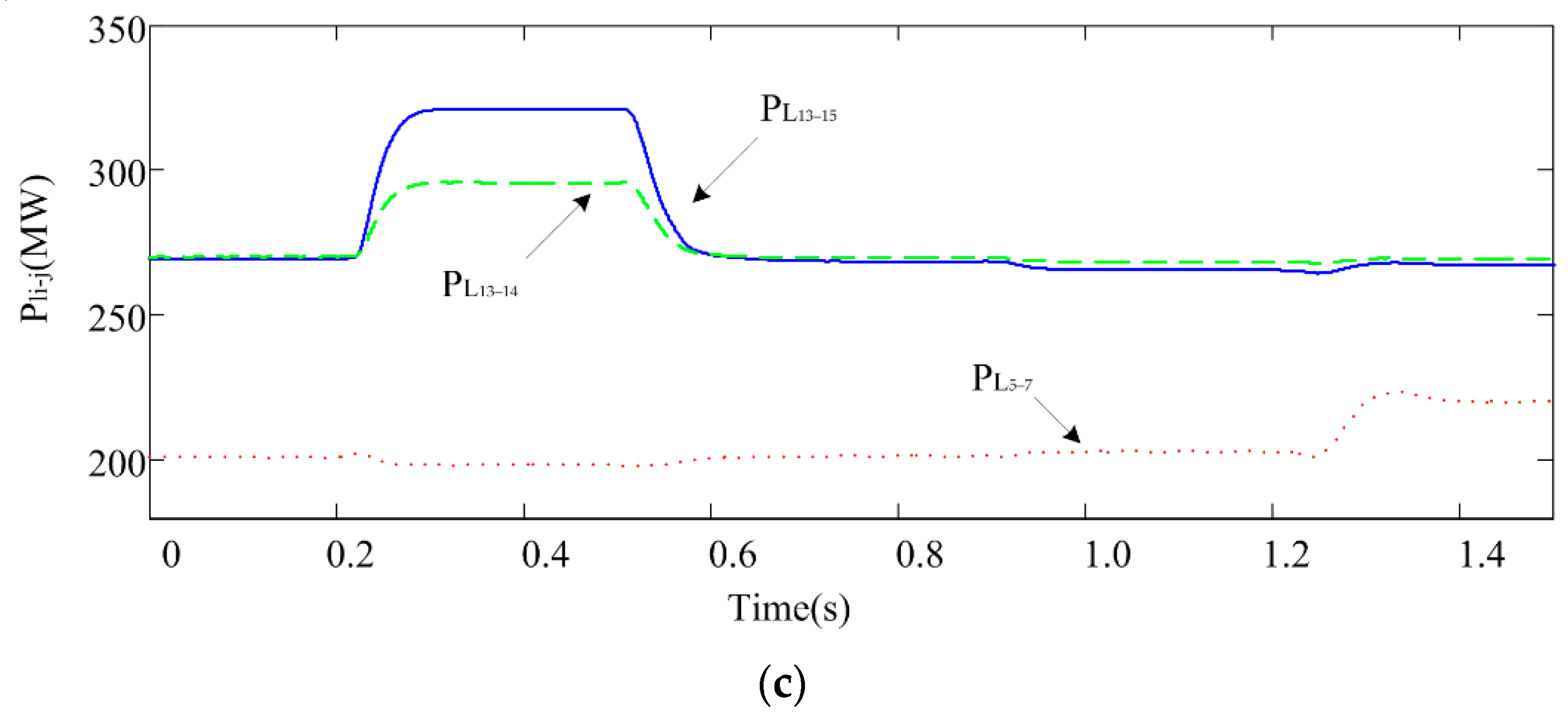
As shown in
Figure 9a,b, when
t = 0.2 s, the master converter is blocked, and active power is decreased to zero immediately. DC unbalance power occurs when the auxiliary converter reaches its maximum capacity. The final unbalanced power is 251 MW, and the operation mode will turn into VSC
2 priority mode. According to equation (15),
UdcL2 of VSC
2 is 391 kV. Then
Udcl2 of the VSC
2 is set at 379 kV as the result of a security margin for DC voltage control of VSC
4. The DC unbalanced power is absorbed by VSC
2 independently. Under VSC
2 priority mode, the DC voltage will rapidly reduce until VSC
2 turns into droop control, and then DC voltage is always within the security range.
At t = 0.9 s, the offshore wind farm outputs the maximum active power and the output of VSC1 and VSC3 are decreased to 181.7 MW and 130.8 MW, respectively. As a result, DC unbalanced power will be changed to 60 MW if VSC1 is out of operation.
When t = 1.2 s, VSC1 will be out of operation for a long time because of a serious fault in the converter. The operation mode will change into VSC4 priority mode, and the DC unbalanced power is absorbed. The DC voltage is within the normal range during the process.
From
Figure 9c, it is observed that the power supply security of critical lines is confirmed during the simulation process. Under VSC
2 priority mode, the sum of active power value of
L13–15 and
L13–14 is 616.4 MW, and the active power of
L5–7 is kept around 199 MW. Under VSC
4 priority mode, the active power of
L5–7 is 220 MW, and the active power variation of
L13–15 and
L13–14 are quite small. The influence on the AC system power flow can be limited in one area.
It can be concluded that, under the priority mode, the APC converter can absorb the DC unbalanced power independently. Meanwhile, power supply security is confirmed, and the influence on power flow can be limited in a small area. In addition, the transmission security of the important power supply area is guaranteed because the important power supply area usually has greater power supply demand. According to the priority control method proposed in this paper, these converters have lower priority. Therefore, they are the last to participate in power regulation when the DC unbalanced power is small.
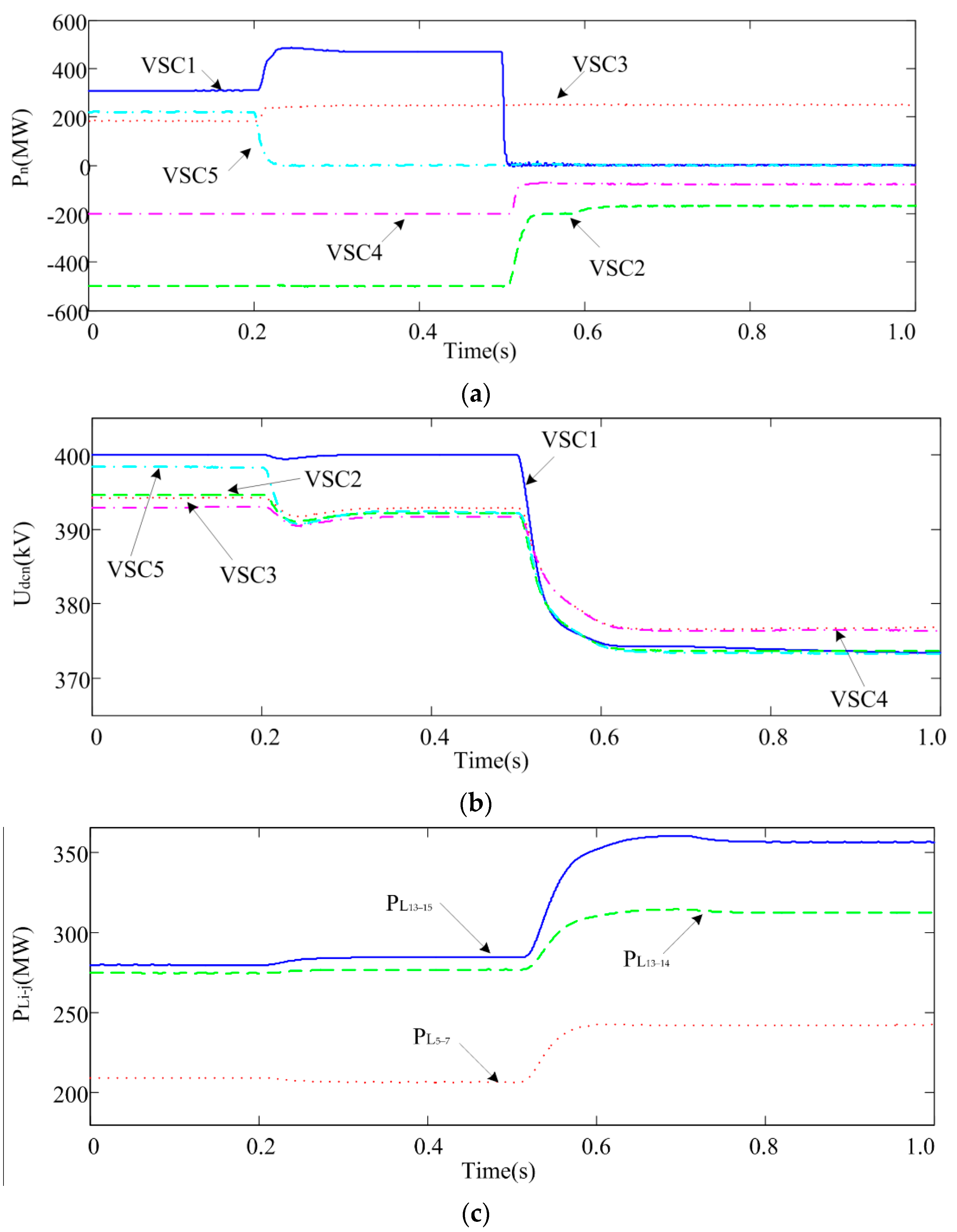
4.2. Simulation under Shared Control Mode
The initial simulation set is similar to 4.1. When
t = 0.2 s, the output of the offshore wind farm is changed to zero. At
t = 0.5 s, converter 1 is blocked due to a temporary fault and unblocked at
t = 0.8 s. Simulation results are shown in
Figure 10.
As shown in
Figure 10a,b, when
t = 0.2 s, the maximum DC unbalanced power is changed to 460 MW since the active power of the offshore wind farm is decreased to zero.
At t = 0.5 s, the master converter is blocked because of a temporary fault, and the active power is reduced to zero. The DC unbalanced power occurs, and the DC voltage reduces rapidly. Since the unbalanced power cannot be absorbed by one converter independently, the operation mode turns into a shared control mode. Similar to case 4.1, UdcL2 and UdcL4 are 391 kV and 390 kV, respectively. Udcl2 and Udcl4 are 379 kV and 383 kV, according to (12), (13), (14), and (16). Under the shared control mode, the DC unbalanced power is absorbed by both VSC2 and VSC4, and the active power is −176.3 MW and −67.1 MW. During the whole process, the DC voltage of all the converters is within the security range. The fault is cleared after 0.3 s, and converters restore to the initial operation mode immediately.
As shown in
Figure 10c, the active power of
L5–7,
L13–15 and
L13–14 are 237.4 MW, 347 MW and 308.4 MW under the shared control mode. The security of all the critical lines is guaranteed, and the load ratio of
L5–7 and
L13–15 +
L13–14 is 0.9309 and 0.9363.
According to the simulation results above, the DC unbalanced power can be well equilibrated by both the two converters under shared mode. The control objectives of power supply security and equal load ratio of critical lines are also realized.
4.3. Simulation under the Special Conditions of the Shared Control Mode
In this case, the load condition is selected No.10 in
Table 5. The active power of the
Load18 and
Load7 is increased by 180 MW and 90 MW, respectively. The maximum regulation capacity of the APC converters is Δ
Pdc2max = 298 MW and Δ
Pdc4max = 122 MW. The initial active power of converter 2, 4 and 5 is 500 MW, 200 MW and 220 MW, respectively. When
t = 0.2 s, the output of the offshore wind farm is changed to zero. At
t = 0.5 s, converter 1 is out of operation because of a serious converter fault. When
t = 0.7 s, the AC system is involved in the control and the active power of the
Load18 is decreased by 40 MW. Simulation results are shown in
Figure 11.
As shown in
Figure 11a,b, when
t = 0.5 s, the master converter is out of operation for a long time because of a serious fault in the converter. Since the DC unbalanced power is 460 MW, shared control mode will be applied in both these two converters. At
t = 0.58 s, the two converters reach their maximum regulation capacity limits, but the DC system still has unbalanced power that is not absorbed. At this time, a special condition of the shared control mode occurs. VSC
2 will continue absorbing the remaining unbalanced power, and VSC
4 maintain the maximum active power allowed. At
t = 0.65 s, the DC unbalanced power is absorbed by both VSC
2 and VSC
4, and the active power is −168 MW and −78 MW. During the whole process, the DC voltage of all the converters is within the security range.
As shown in
Figure 11c, the active power of
L5–7,
L13–15 and
L13–14 are 242.5 MW, 360.5 MW and 314.5 MW under the special condition of the shared control mode, respectively. The load ratio of
L5–7 and
L13–15 +
L13–14 is 0.95 and 0.9642, respectively. Under this condition, the load ratio of
L13–15 +
L13–14 exceeds the allowable security range, and the AC system is involved in control. After the active power of the
Load18 is decreased by 40 MW at
t = 0.7 s, the active power of
L13–15 and
L13–14 are 353 MW and 311.5 MW, respectively. The final load ratio of
L5–7 and
L13–15 +
L13–14 is 0.95 and 0.949, respectively.
According to the simulation results above, a special condition of the shared control mode occurs when the total regulation capacity is insufficient. At this time, the VSC interconnected with a strong area will continue absorbing unbalanced power, and the others maintain the maximum power allowed. Since system security cannot be protected by the DC system alone, the AC system should be involved in the regulation. Through the coordination of the AC and DC system, the power supply security of the urban power grid is guaranteed.


